

Page 1
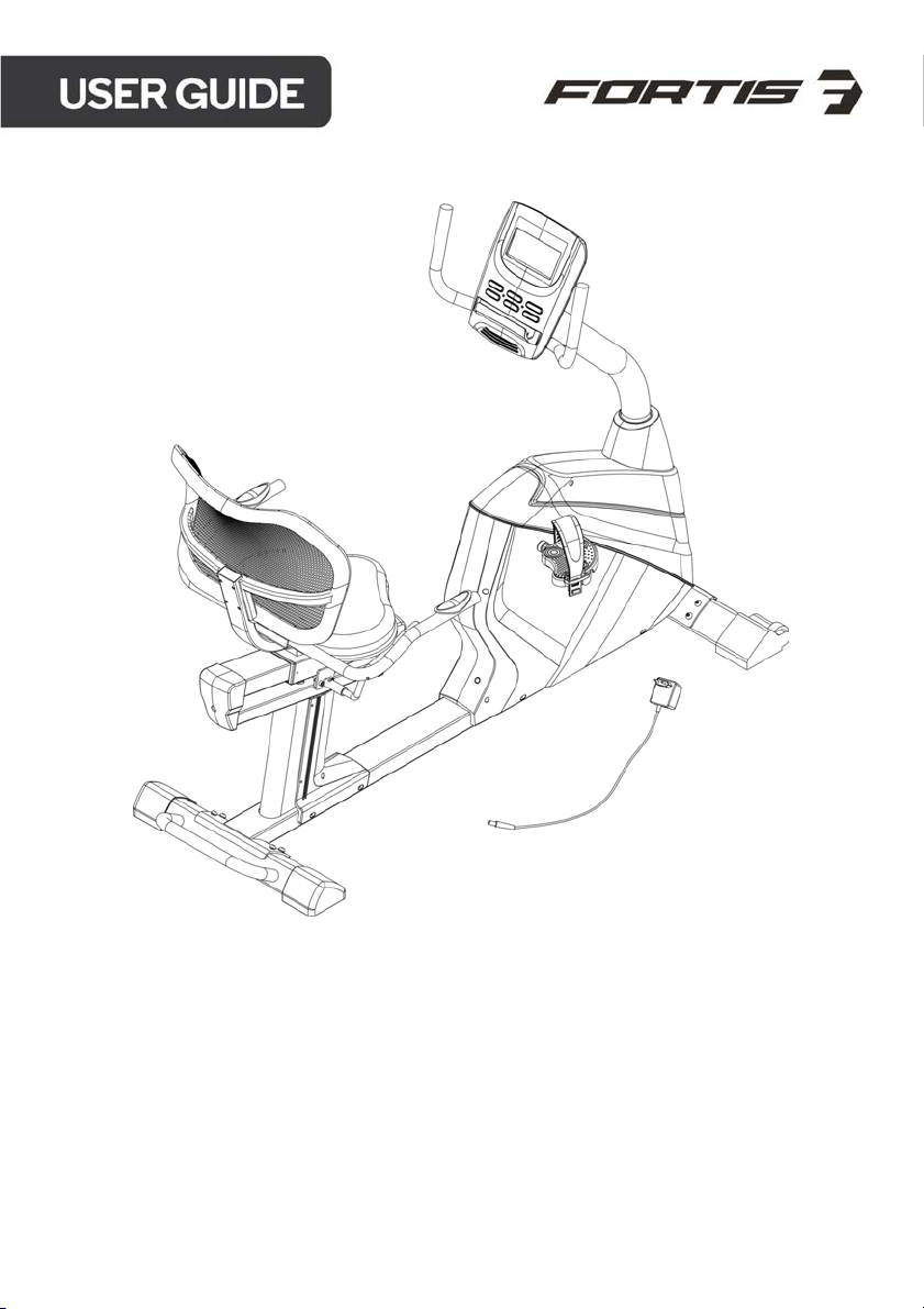
FORTIS ELECTRIC MAGNETIC
RECUMBENT BIKE
(RC-400A)
FSARCB400AA
Page 2

Contents
2
Safety & warnings
3
Overview
5
Assembly
9
Operation
17
Programs
19
2
Page 3

Read all of the instructions in this guide before using this product. Retain this guide for future
reference. Do not skip, substitute or modify any steps or procedures in this guide, as doing so
could result in personal injury or product damage.
• Before starting any exercise program, consult your physician to determine if you
have any medical or physical conditions that could put your health and safety at
risk or prevent you from using the equipment properly. Your physician’s advice is
essential if you are taking any medication that may affect your heart rate, blood
pressure or cholesterol level.
• Incorrect or excessive exercise can damage your health. Stop exercising if you
experience any of the following symptoms: pain, tightness in your chest, irregular
heartbeat, shortness of breath, light headedness, dizziness or feelings of nausea. If
you experience any of these conditions, you should consult your physician before
continuing with your exercise program.
• This equipment is intended for adult use only. Keep children and pets away from
the machine. DO NOT leave children unattended in the same room with the
equipment.
• This appliance is designed for consumer use. Follow directions and use only as
described.
• Once fully assembled, inspect to ensure all hardware parts such as bolts, nuts and
washers are positioned correctly and tightly secured.
• Always inspect the safety chain guard that protects the moving parts of the bike to
be in safe and good order.
• Always inspect the seat post, seat slider, pedals and handlebar to make sure they
are in safe and stable position before using the bike.
• It is recommended to lubricate all moving parts on a monthly basis.
• Do not wear loose clothing while riding.
• Do not remove feet from the pedals while they are in motion. Wear running shoes
or other footwear suitable for exercise.
• Dry after each use to remove moisture. Wipe regularly with a mild, non-abrasive
cleaner and water solution. To avoid damaging the finish, never use a petroleumbased solvent.
• Do not dismount the bike until the pedals are at a complete stop.
• Use the equipment on a solid, flat level surface with a protective cover for your floor
or carpet. To ensure safety, the equipment should have at least 2 feet
(approximately 60 cm) of free space on each side.
3
Page 4

• Prior to assembly, ensure you have all the components and tools listed. Some
components are pre-assembled to help with the assembly process.
• Always use the equipment as intended. If you find any defective components while
assembling or checking the equipment, or if you hear any unusual noises coming
from the equipment during exercise, cease use immediately and contact
help.kogan.com for assistance. Do not use until resolved.
• Do not place fingers or any other objects into moving parts of the exercise
equipment.
• After exercising, turn the adjusting Knob to increase tension so the pedals will not
rotate freely and possibly hurt someone while bike is not in use.
• Do not exceed the maximum user weight of 120 KG.
• Be careful when lifting and moving the equipment. Always use proper lifting
technique and seek assistance if necessary.
• Yo ur e qu i p me n t is i nt e n de d fo r us e i n c o ol , d ry c o nd i t io n s . Yo u sh o u ld a vo i d st o ra g e
in extreme cold, hot or damp areas as this may lead to corrosion and other related
problems.
o Operating temperature: 0 - 40 °C
o Storage temperature: -10 - 60°C
• This appliance contains no user-serviceable parts. If it suffers any failure or
damage, cease use immediately and contact help.kogan.com
• This equipment is designed and intended for indoor use only.
4
Page 5
5
Page 6
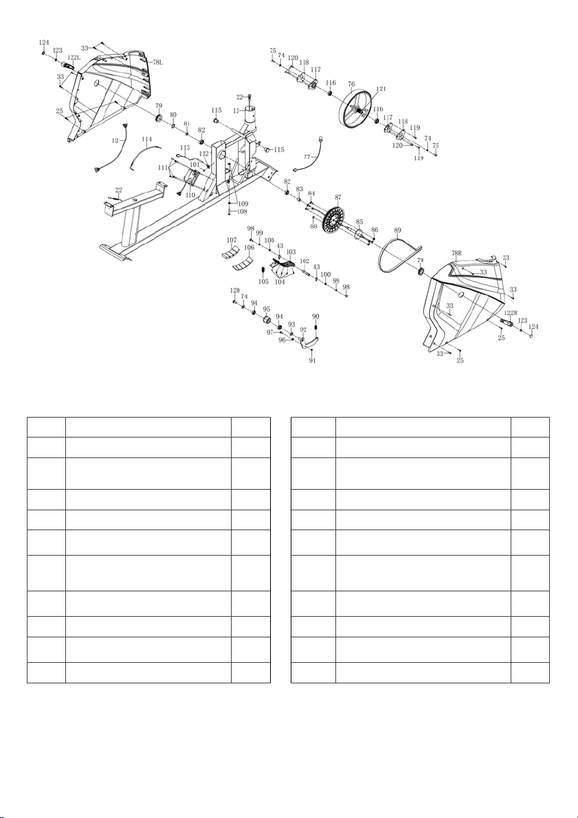
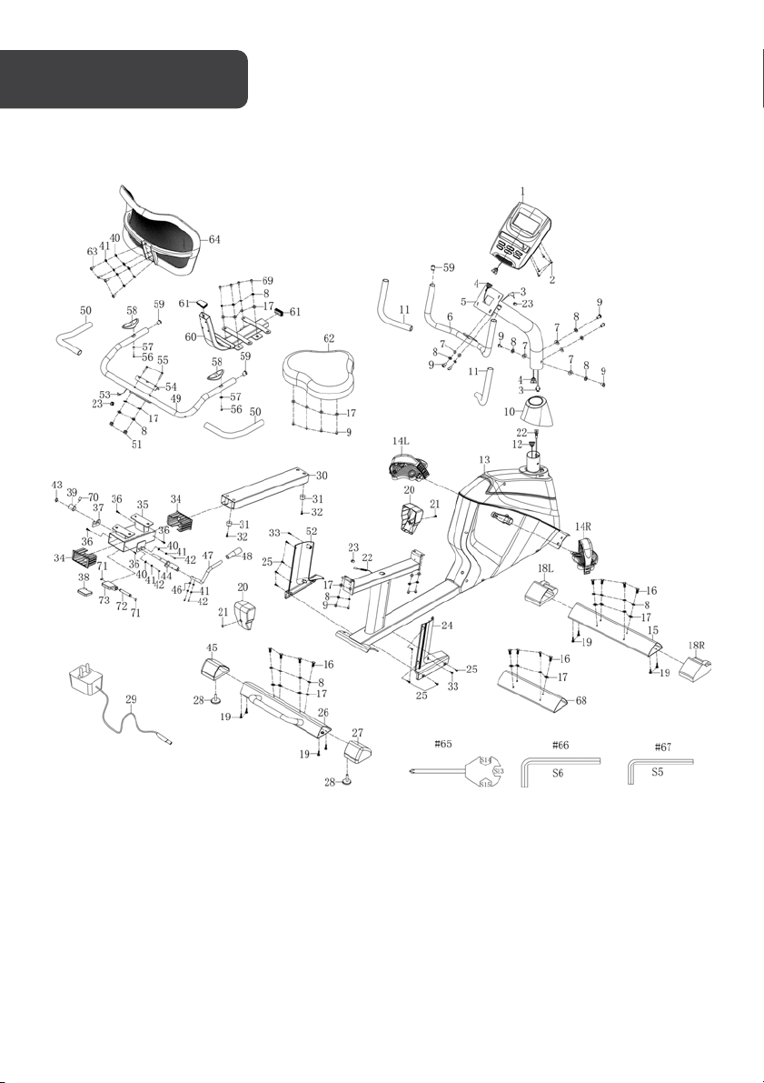
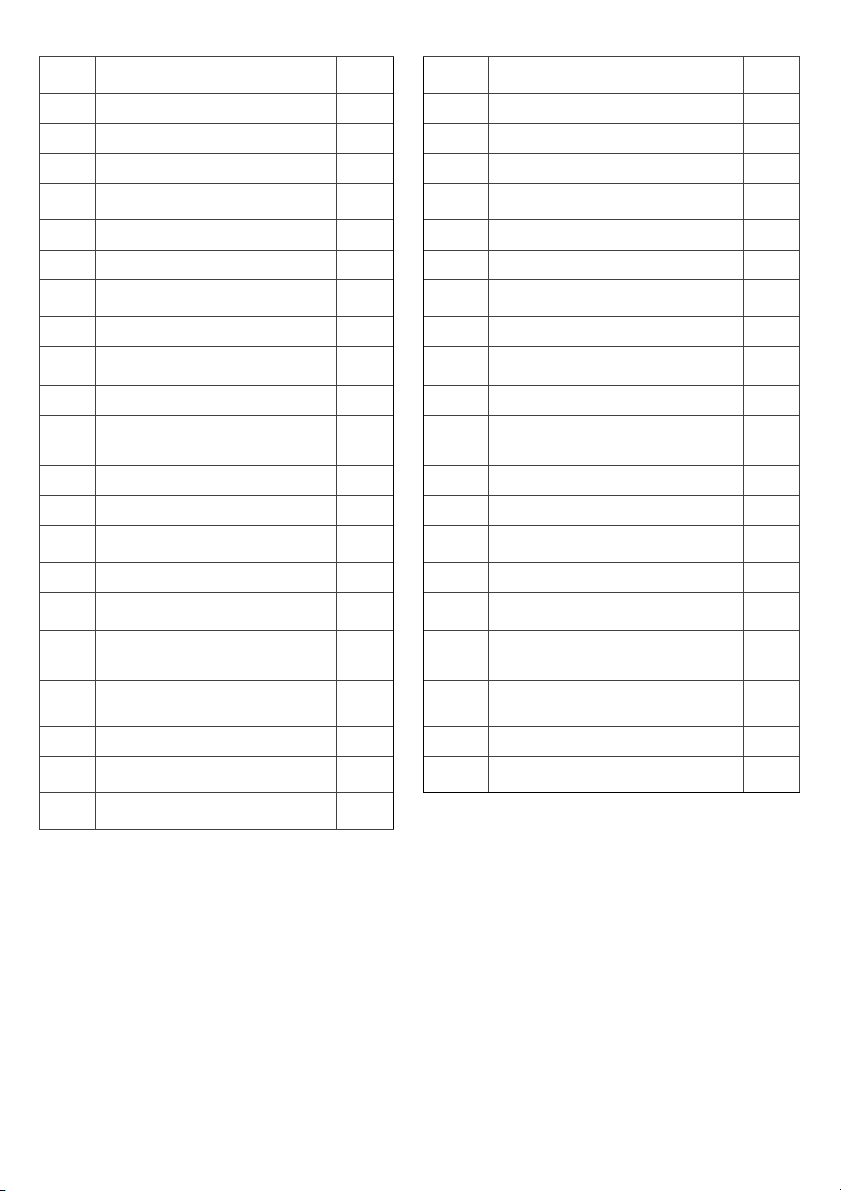
Part List
No
Description
Qty No
Description
Qty
1
Console
x1 13
Main frame
x1
2
Screw M5 x 10 x Φ10
x4
14
L/R
Pedal L/R
x2
4
Mid sensor wire 1
x1 15
Front stabilizer
x1
5
Handlebar post
x1 16
Hex bolt M8 x 20 x S13
x12
6
Handlebar
x1 17
Washer d8 x Φ20 x 2
x26
7
Arc washer d8 x ФΦ20 x 2 x
R30
x6 18
Front stabilizer cap L/R
x2
9
Screw M8 x 16 x S6
x14 19
Screw ST ST4.2 x 25 Φ8
x8
10
Post cover
x1 20
Rear slider cover
x2
11
Foam grip Φ23 x 3 x 330
x2 21
Screw M5 x 8 x Φ8
x2
12
Mid sensor wire 2
1
22
Tr u n k l i n e 1
x1
6
Page 7
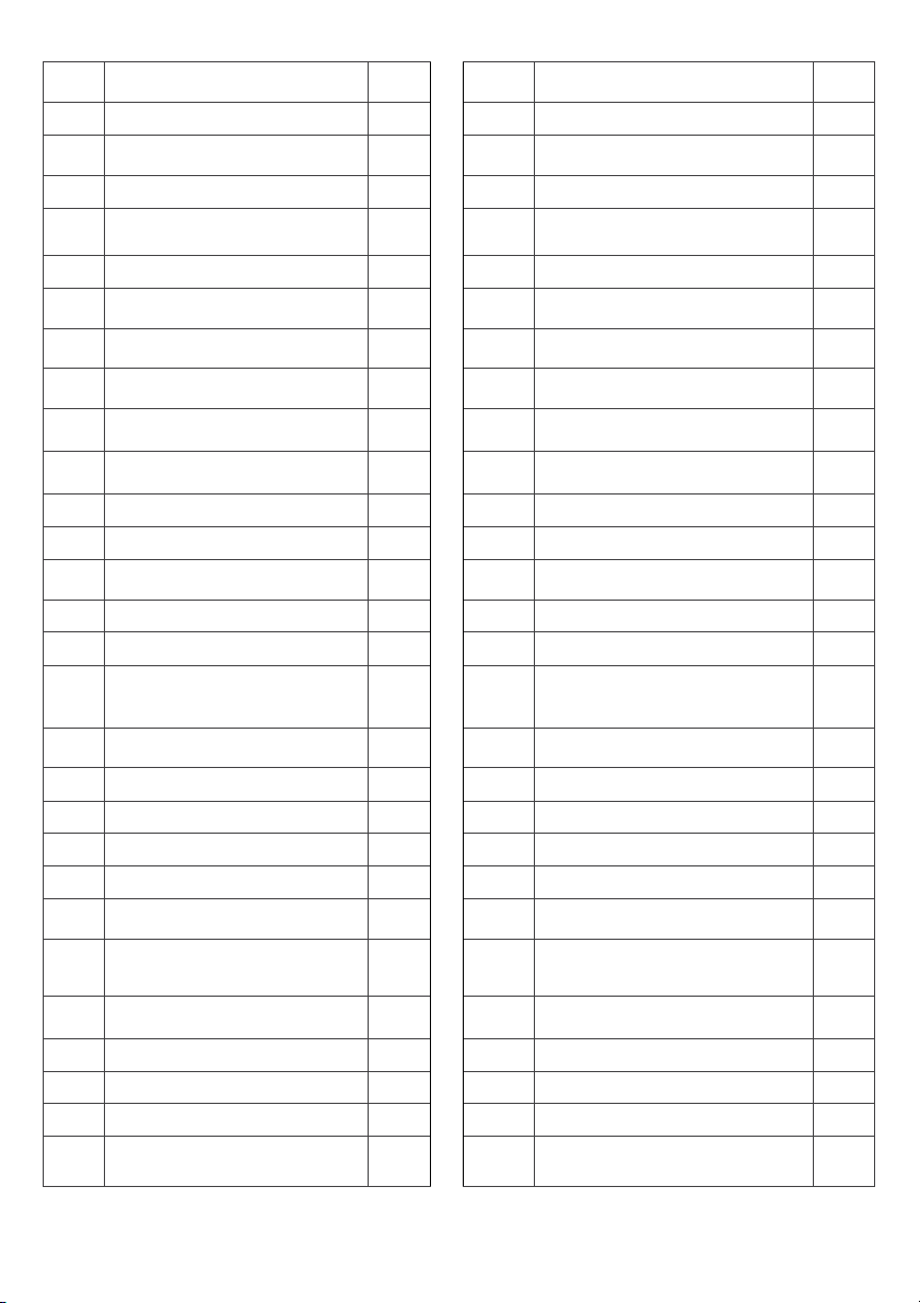
23
Cap Φ12 x 11 x Φ3
x3
50
Foam grip Φ23 x 5 x 500
x2
24
Right handlebar cover
x1 51
Nut M8 x H16 x S13
x2
25
Screws ST4.2 x 16 x Φ8
x12 52
Left handlebar cover
x1
26
Rear stabilizer
x1 53
Handle pulse wire
x1
27
Rear stabilizer cap-right
x1 54
Handlebar cover t3 x 38 x
130
x1
28
Adjustable foot
x2 55
Bolt M8 x 47 x 20 x H5
x2
29
Adaptor
x1 56
Screw ST4 x 19 x Φ7
x2
30
Slider rail
x1 57
Washer d5 x Φ10 x 1.0
x2
31
Cushion Φ22 x Φ18 x 16 x Φ4
x2 58
Handle pulse
x2
32
Screw ST4.2 x 16 x ΦΦ9
x2 59
Handlebar cap Φ25 x 16
x4
33
Screw ST4.2 x 19 x ΦΦ8
x11 60
Seat post
x1
34
Rail sleeve J50 x 100 x 60
x2 61
Seat post cap J50 x 25 x 14
x2
35
Seat slider
x1 62
Seat
x1
36
Screw ST3 x 8 x Φ5.6
x4 63
Screw M6 x 45 x Φ12
x4
37
Handle plate
x1 64
Back pad 400 x 450 x 135
x1
38
Rubber mat 51 x 44 x 9.7
x1 65
Wrench S13-14-15
x1
39
Adjustment block Φ25 x
Φ30
x1 66
Allen wrench S6
x1
40
Washer d6 x Φ12 x 1.2
x6 67
Allen wrench S5
x1
41
Washer d6
x8 68
Mounting plate
x1
42
Bolt M6 x 20 x S5
x4 69
Bolt M8 x 20 x S6
x4
43
Shaft Ring d12
x3 70
Bolt M8 x 10
x1
44
Adjustment lever shaft
x1 71
Shaft Ring d10
x2
45
Rear stabilizer cap-left
x1 72
Seat stop shaft Φ10.1 x 64
x1
46
Arc washer d6 x Ф16 x 1.5 x
R16
x2 73
Anti-skid plate
x1
47
Adjustment handle
x1 74
Washer d6 x ΦΦ16 x 1.5
x3
48
Adjustment handle knob
x1 75
Hex bolt12mm
x2
49
Lower handlebar
x1 76
Flywheel
x1
77
Power wire
x1 102
Magnetic board axle
x1
78
L/R
Chain cover L/R
x2 103
Magnetic board
x1
7
Page 8
79
Crank hole cap
x2 104
Screw ST ST3 x 10 x Φ5.6
x5
80
Shaft Ring d17
x1 105
Tension spring
x1
81
washer
x1 106
Magnet seat 45.5 x 130 x 10.5
x1
82
Bearing 6203-2RS
x2 107
Square magnet 39 x 24.5 x 10
x4
83
Bushing Φ22 x Φ17.1 x 5.5
x1 108
Hex boltM6 x 45 x S10
x1
84
Hex bolt 16mm
x4 109
Nut M6 x H5 x S10
x2
85
Middle Axle
x1 110
Resistance motor
x1
86
Nylon nut M6 x H6 x S10
x4 111
Screw ST4.2 x 16 x Φ8
x4
87
Belt plate
x1 112
Sensor seat
x1
88
Magnet φΦ15 x 7
x1 113
Speed sensor
x1
89
Belt
x1 114
Tension wire
x1
90
Tension spring Φ2.0 x Φ12 x
79 x N27
x1 115
Cap φ25 x 22
x2
91
Nylon nut M8 x H7.5 x S13
x1 116
Bearing 6001-2RS
x2
92
Idle wheel bracket
x1 117
Bearing bracket
x2
93
Wave washerd12 x Φ17 x 0.3
x1 118
Bearing plate
x2
94
Bearing 6001-2RS
x2 119
Bolt M6 x 8 x S10
x2
95
Idler wheel Ф39 x Ф34 x 24
x1 120
Bolt M6 x 10 x S10
x5
97
Screw M8 x 12 x Φ10 x 5 x
S12
x1 121
Flywheel Axle
x1
98
Hex bolt 16mm
x2
122
L/R
Crank
x2
99
Washer d6
x2 123
Nut M10 x 1.25 x H7.5 x S14
x2
100
Washer d6 x Φ12 x 1.2
x2 124
Crank cover
x2
101
Screw ST4.2 x 19 x Φ8
x1
8
Page 9
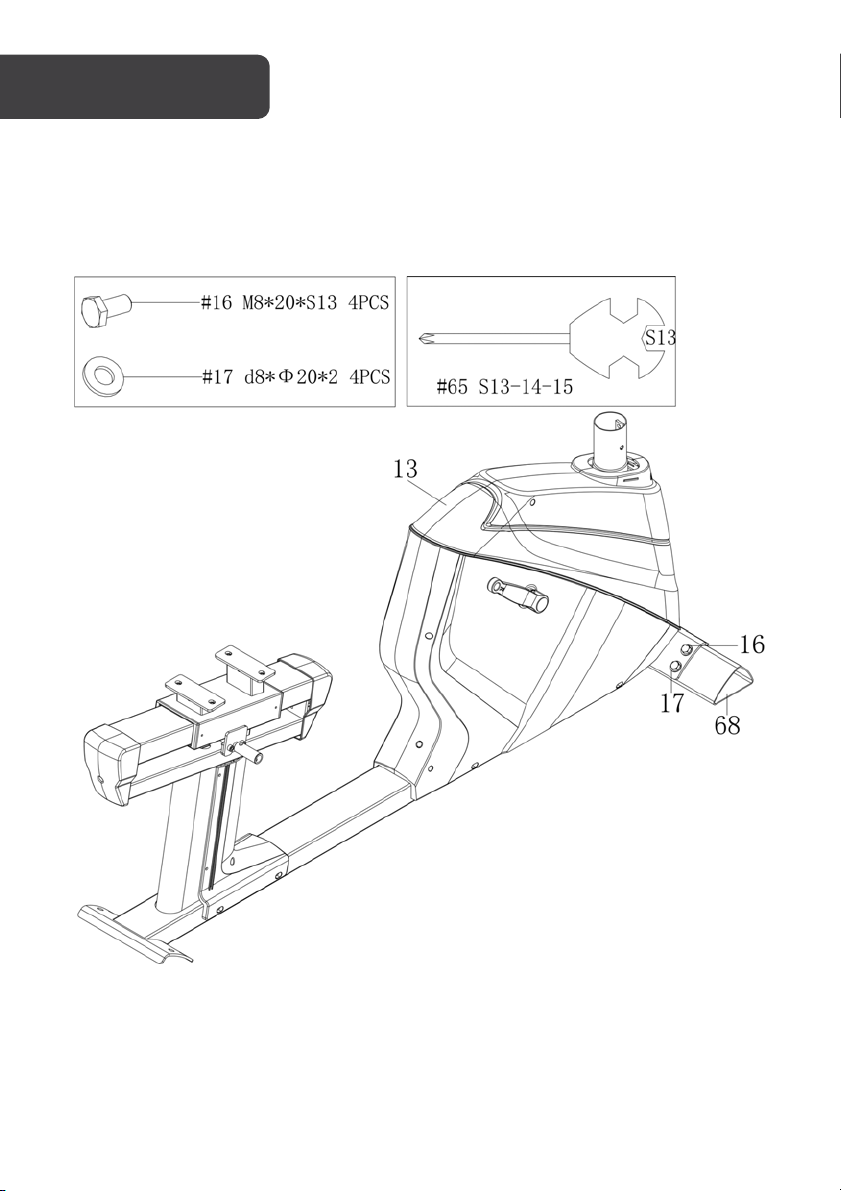
Step 1
Remove the x4 Hex Bolts (16) and x4 Washers (17) from the Mounting Plate (68) using the
Wrench (65).
Set the Hardware and the Mounting Plate (68) aside.
9
Page 10
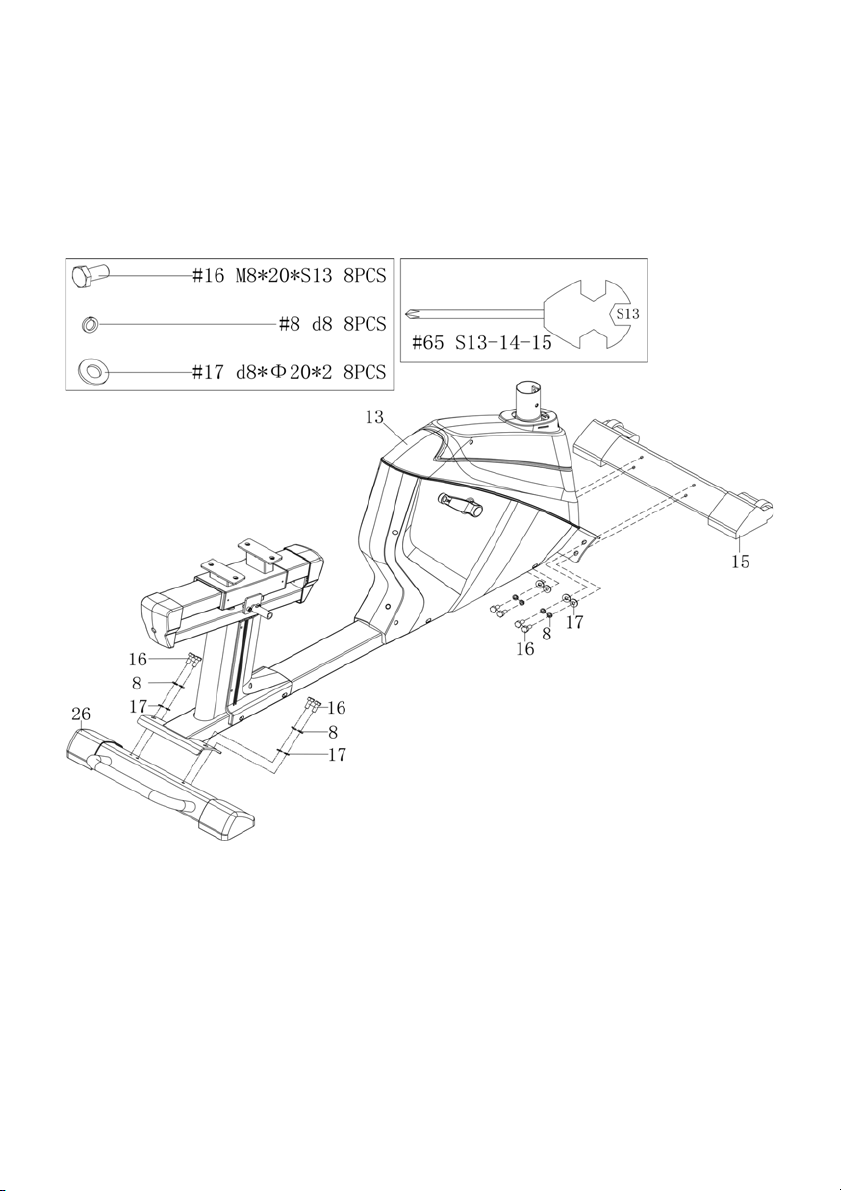
Step 2
Use the Wrench (65) to unscrew the x8 Hex Bolts (16) and take off the x8 Spring Washers (8)
and Washers (17). Set them aside for stabilizer attachment.
Assemble the Front Stabilizer (15) on the Main Frame (13) with x4 Hex Bolts (16), x4 Spring
Washers (8) and x4 Washers (17). Secure them with the Wrench (65). Assemble the Rear
Stabilizer (26) on the Main Frame (13) with x4 Hex Bolts (16), x4 Spring Washers (8) and x4
Washers (17). Secure them with the Wrench (65).
10
Page 11
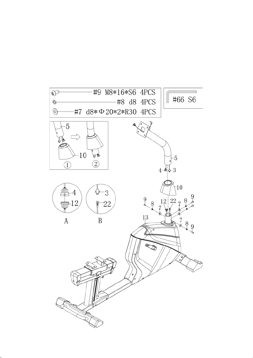
Step 3
Use the Allen Wrench (66) to unscrew the x4 Screws (9), x4 Spring Washers 8mm (8) and x4
Arc Washers (7) from the Handlebar Post (5).
Slide the Post Cover (10) onto the Handlebar Post (5) and connect the Mid Sensor Wire 1 (4)
at the bottom of the Handlebar Post (5) with the Mid Sensor Wire 2 (12) coming out of the
Main Frame (13). Connect the Trunk Line 2 (3) to Trunk Line 1 (22).
Slide the Handlebar Post (5) on to the Main Frame (13) and secure with x4 Screws (9), x4
Spring Washers (8) and x4 Arc Washers (7). Tighten with Allen Wrench (66).
11
Page 12
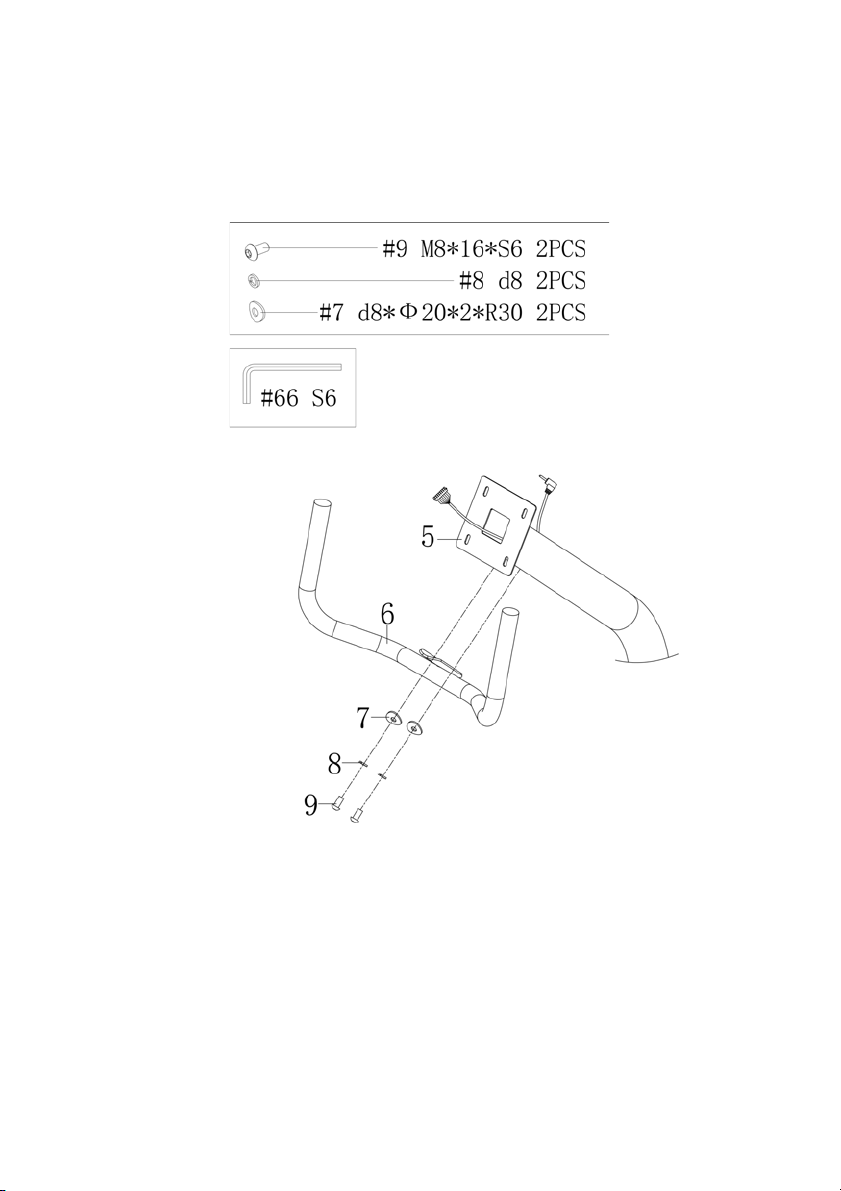
Step 4
Use the Allen Wrench (66) to unscrew the x2 Screws (9), x2 Spring Washers (8) and x2 Arc
Washers (7) from the Handlebar Post (5).
Attach the Handlebar (6) to the Handlebar Post (5) with x2 Screws (9), x2 Spring Washers (8)
and x2 Arc Washers (7). Tighten with Allen Wrench (66).
12
Page 13
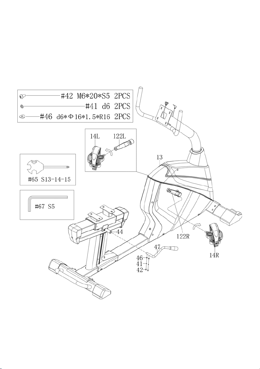
Step 5
Use the Allen Wrench (67) to unscrew x2 Screws (42), x2 Washers (41) and x2 Arc Washers
(46) from the Adjustable Handle (47). Attach the Adjustable Handle (47) to the Adjustment
lever shaft (44) with the screws and washers you just took off the Adjustable Handle (47).
Use the Allen Wrench (67) to secure.
Attach the Pedal (14 L/R). First attach the left pedal (14L) and tightens counter-clockwise in
the Crank (122L), Then attach the right pedal (14R), it tightens clockwise in the Crank (122R).
Use the Wrench (65) to tighten the pedals.
13
Page 14
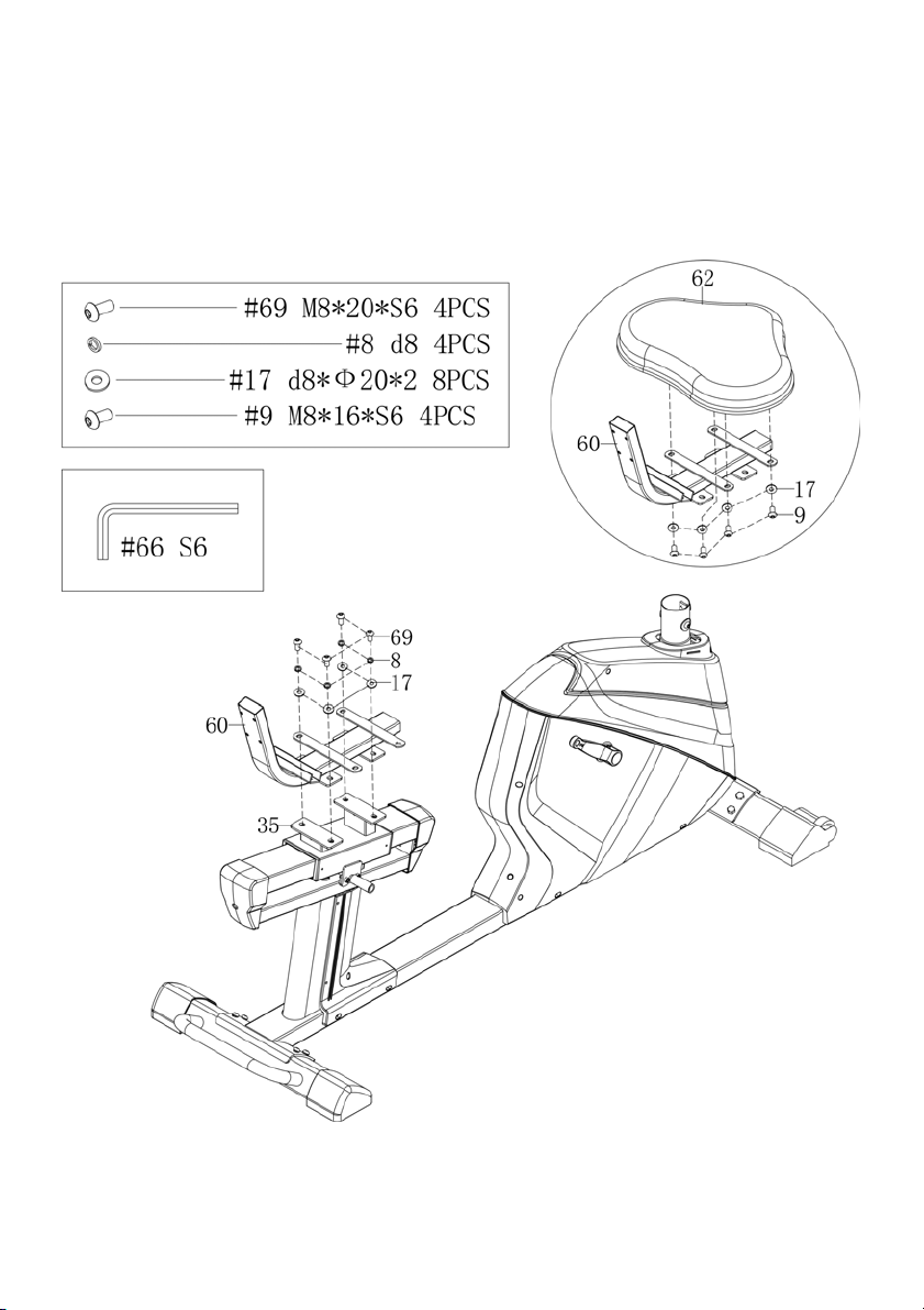
Step 6
Use the Allen Wrench (66) to unscrew the 4 Bolts (69), x4 Spring Washers (8) and x4
Washers (17) from the Seat Slider (35). Attach the Seat Post (60) to the Seat Slider (35) with
x4 Bolts (69), x4 Spring Washers (8) and x4 Washers (17)
Use the Allen Wrench (66) to unscrew the x4 Screws (9) and x4 Washers (17) from the Seat
(62). Attach the Seat (62) to the Seat Post (60) with x4 Screws (9) and x4 Washers (17).
14
Page 15
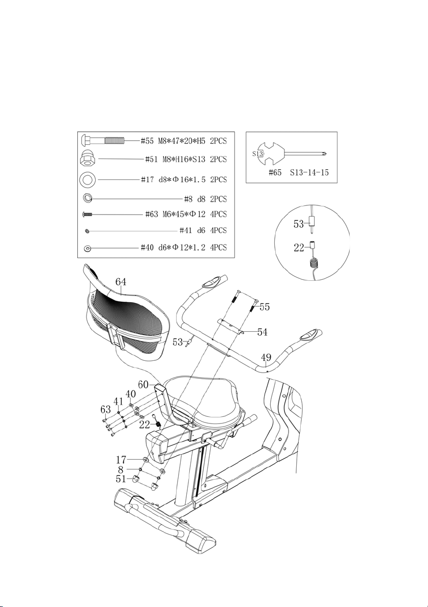
Step 7
Use the Wrench (65) to unscrew the x4 Screws (63), x4 Washers (41) and x4 Washers (40)
from the Back Pad (64). Attach the Back Pad (64) to the Seat Post (60) with 4 Screws (63),
x4 Washers (41) and x4 Washers (40). Secure with Wrench (65).
Attach the Handlebar (49) to the Seat Post (60) with x2 Bolts (55), x2 Washers (17), x2
Spring Washers (8), x2 Nuts (51) and Handlebar Cover (54). Then connect the Hand Pulse
Wire (53) to the Trunk Wire (22) coming out of the back of the Main Frame.
15
Page 16
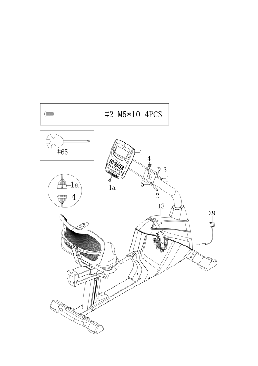
Step 8
Unscrew the x4 screws (2) in the back of the Console (1) with Wrench (65) and set aside.
Connect the Console Wire (1a) with the Mid Sensor Wire 1 (4). Push the wires down into the
Handlebar Post (5), so they don’t get pinched. Attach the Console (1) to the Handlebar Post
(5) with x4 Screws (2). Use Wrench (65) to secure the screws. Then plug in the Trunk Line (3)
into the hole in the rear of the Console (1).
Move your machine by grasping the bar on the rear stabilizer and lifting until the wheels
touch the ground, then move the machine to your desired location. Level with the two
adjustable feet on the bottom of the Rear Stabilizer.
Plug in the Adaptor (29) into a wall socket and then the socket in the front of the machine.
16
Page 17

1. Tu r n o n t h e co m p u t e r
Plug in one end of the adaptor to a wall outlet and connect the other end to the computer.
The computer will beep and enter into Manual mode.
2. Program select and value setting
• Use the UP or DOWN keys to select program mode and then press ENTER to
confirm your exercise mode.
• At the Manual mode, the computer will use the UP or DOWN keys to set up your
exercise TIME, DISTANCE, CALORIES, PULSE.
• Press the START/STOP key to start exercise.
• When you reach the target, the computer will produce beep sounds and then stop.
• If you set up more than one target and you would like to reach next target, press
START/STOP key to keep on exercise.
3. Wake-Up Function
The monitor will entry SLEEP mode (LCD off) when there is no signal input and no key be
pressed after 4 minutes. Press the screen to start the monitor.
Functions and Feat ures:
• TIME: Shows your elapsed workout time in minutes and seconds. Your computer
will automatically count up from 0:00 to 99:59 in one second intervals. You can
also program your computer to count down from a set value by using the UP and
DOWN keys. If you continue exercising once the time has reached 0:00, the
computer will begin beeping, and reset itself to the original time set, letting you
know your workout is done.
• DISTANCE: Displays the accumulative distance travelled during each workout up
to a maximum of 99.99KM/MILE.
• RPM: Your pedal cadence.
• SPEED: Displays your workout speed value in KM/MILE per hour.
• CALORIES: Your computer will estimate the cumulative calories burned at any
given time during your workout.
• PULSE: Your computer displays your pulse rate in beats per minute during your
workout.
• AGE: Your computer is age-programmable from 10 to 99 years. If you do not set an
age, this function will always default to age 35.
17
Page 18

• TA RG ET HE AR T RAT E (TA R GE T PU LS E) : T he h ea r t ra te y o u sh ou l d ma in ta in i s
Note:
If no pulse signal input then the computer will show “P” on the PULSE window. If the
computer shows “ERR” on the message window, please re-press the PULSE
RECOVERY key and please make sure your hands are keeping well on the grips.
called your Target Hear Rate in beats per minute.
4. Key Function
There are 6 button keys and the function description as follows:
START/STOP key:
• Quick Start function: Allows you to start the computer without selecting a program.
Manual workout only. Time automatically begins to count up from zero
• During the exercise mode, press the key to STOP exercise.
• During the stop mode, press the key to START exercise.
UP key:
• Press the key to increase the resistance during exercise mode.
• During the setting mode, press the key to increase the value of Time, Distance,
Calories, Age and select Gender and Program.
DOWN key:
• Press the key to decrease the resistance during exercise mode.
• During the setting mode, press the key to decrease the value of Time, Distance,
Calories, Age and select Gender and Program.
ENTER key:
1. During the setting mode, press the key to accept the current data entry.
2. At the stop mode, by holding this key for over two seconds the user can reset all
values to zero or default value.
3. During setting the Clock, press this key can accept the setting hour and setting
minute.
BODY FAT key:
Press the key to input your HEIGHT, WEKGHT, GENDER and AGE then to measure your
body fat ratio.
PULSE RECOVERY key:
Press the key to activate heart rate recovery function.
18
Page 19

P2
Steps
P8
Mountain
P3
Hill
P9
Intervals
P4
Rolling
P10
Random
P5
Valley
P11
Plateau
P6
Fat Burn
P12
Fartlek
P7
Ramp
P13
Precipice Program
P1: Manual program
User can start exercise by pressing START/STOP key. The default resistance level is 5. Users
may exercise in any desirous of resistance level (Adjusting by UP/DOWN keys during the
workout) with a period of time or a number of calories or a certain distance.
4. Use UP/DOWN keys to select the MANUAL (P1) program.
5. Press the ENTER key to enter MANUAL program.
6. The TIME will flash and you can press UP or DOWN keys to set your exercise TIME.
Press ENTER key to confirm your desired TIME.
7. The DISTANCE will flash and you can press UP or DOWN keys to set your target
DISTANCE. Press ENTER key to confirm your desired DISTANCE.
8. The CALORIES will flash and you can press UP or DOWN keys to set your exercise
CALORIES. Press
9. ENTER key to confirm your desired CALORIES.
10. The PULSE will flash and then you can press UP or DOWN keys to set your exercise
PULSE. Press ENTER key to confirm your desired Pulse.
11. Press the START/STOP key to begin exercise.
P2 - P13: Preset programs
Users can exercise with different level of loading in different intervals as the profiles show.
Users may exercise in any desirous of resistance level (Adjusting by UP/DOWN keys during
the workout) with a period of time or a number of calories or a certain distance.
1. Use UP/DOWN keys to select one of the above programs from P2 to P13.
2. Press the ENTER key to enter your workout program.
3. The TIME will flash and you can press UP or DOWN keys to setting your exercise
TIME. Press ENTER key to
4. confirm your desired TIME.
5. The DISTANCE will flash and you can press UP or DOWN keys to setting your
target DISTANCE. Press ENTER key to confirm your desired DISTANCE.
6. The CALORIES will flash and you can press UP or DOWN keys to setting your
exercise CALORIES. Press ENTER key to confirm your desired CALORIES.
19
Page 20

7. The PULSE will flash and then you can press UP or DOWN keys to set your exercise
PULSE. Press ENTER key to confirm your desired Pulse.
8. Press the START/STOP key to begin exercise.
P14 - P17: User Setting Programs
User 1, User 2, User 3, User 4 are the user setting programs
Users are free to create the values in the order of TIME, DISTANCE, CALORIES and the
resistance level in 10 columns. The values and profiles will be stored in the memory after
setup. Users may also change the ongoing loading in each column by UP/DOWN keys, and
they will not change the resistance level stored in the memory.
1. Use UP/DOWN keys to select the USER program from P14 to P17.
2. Press the ENTER key to enter your workout program.
3. The column 1 will flash, and then use the UP/DOWN keys to create your personal
exercise profile. Press ENTER to confirm your first column of exercise profile. The
default level is load 1.
4. The column 2 will flash, and then use the UP/DOWN keys to create your personal
exercise profile. Press ENTER to confirm your second column of exercise profile.
5. Fol low the abo ve desc ript io n 5 and 6 t o fi nish your personal exercise profiles. Press
ENTER to confirm your desired exercise profile.
6. The TIME will flash and you can press UP or DOWN keys to setting your exercise
TIME. Press ENTER key to confirm your desired TIME.
7. The DISTANCE will flash and you can press UP or DOWN keys to setting your
target DISTANCE. Press ENTER key to confirm your desired DISTANCE.
8. The CALORIES will flash and you can press UP or DOWN keys to setting your
exercise CALORIES. Press ENTER key to confirm your desired CALORIES.
9. The PULSE will flash and then you can press UP or DOWN keys to set your exercise
PULSE. Press ENTER key to confirm your desired Pulse.
10. Press the START/STOP key to begin exercise.
P18 - P22: Heart Rate Control Programs
• P18 is the 55% Max H.R.C. - - Ta r g e t H . R . = ( 2 2 0 – AGE) x 55%
• P19 is the 65% Max H.R.C. - - Ta r g e t H . R . = ( 2 2 0 – AGE) x 65%
• P20 is the 75% Max H.R.C. - - Ta r g e t H . R . = ( 2 2 0 – AGE) x 75%
• P21 is the 85% Max H.R.C. - - Ta r g e t H . R . = ( 2 2 0 – AGE) x 85%
• P22 is the Target H.R.C. - - Workout by your target heart rate value.
Users can exercise according to your desired Heart Rate program by setting your AGE,
TIME, DISTANCE, CALORIES or TARGET PULSE. In these programs, the computer will
adjust the resistance level according to the heart rate detected. For example, the resistance
level may increase every 20 seconds while the heart rate detected is lower than the
TARGET H.R.C. Also the resistance level may decrease every 20 seconds while the heart
rate detected is higher than the TARGET H.R.C.
20
Page 21

1. Use UP/DOWN keys to select one of the heart rate control program from P18 to
≧
P22.
2. Press the ENTER key to enter your workout program
3. The AGE will flash at P18 to P21 programs and you can press UP or DOWN keys to
set your AGE. The default age is 35.
4. At program 22, the TARGET PULSE will flash and you can press UP or DOWN keys
to set your TARGET
5. PULSE between 80 to 180. The default TARGET PULSE is 120.
6. The TIME will flash and you can press UP or DOWN keys to set your exercise TIME.
Press ENTER key to confirm your desired TIME.
7. The DISTANCE will flash and you can press UP or DOWN keys to set your target
DISTANCE. Press ENTER key to confirm your desired DISTANCE.
8. The CALORIES will flash and you can press UP or DOWN keys to set your exercise
CALORIES. Press ENTER key to confirm your desired CALORIES.
9. Press the START/STOP key to begin exercise.
P23: Body Fat Program: Body Fat
P23 is a special program design to calculate users’ body fat ratio and to offer a specific
loading profile for users. There are 3 body types divided according to the FAT% calculated.
• Ty p e 1 : B O DY F AT % > 2 7
• Ty p e 2 : 2 7
BODY FAT% ≧ 20
• Ty p e 3 : B O DY F AT % < 2 0
The computer will show the test results of FAT PERCENT, BMI and BMR.
1. Use UP/DOWN keys to select the BODY FAT (P23) program.
2. Press the ENTER key to enter your workout program.
3. The HEIGHT will flash and you can press UP or DOWN keys to set your HEIGHT.
Press ENTER key to confirm your HEIGHT. The default HEIGHT is 170cm or 5’07”
(5feet 7 inches).
4. The WEIGHT will flash and you can press UP or DOWN keys to set your WEIGHT.
Press ENTER key to confirm your WEIGHT. The default WEIGHT is 70kgs or 155lbs.
5. The GENDER will flash and you can press UP or DOWN keys to select your sex.
Number 1 means man and number 0 means female. Press ENTER key to confirm
your Gender. The default sex Is 1 (MAN).
6. The AGE will flash and you can press UP or DOWN keys to set your AGE. Press
ENTER key to confirm your AGE. The default AGE is 35.
7. Press the START/STOP key to begin body fat measurement. If the window show E
on the window, please make sure your hands are attached well on the grips or the
chest belt is touch well on your body. Then press the START/STOP key again to
begin body fat measurement.
8. After finished your measurement, the computer will show the values of BMR, BMI
and FAT PERCENT on the LCD display. Furthermore, the computer will show your
own exercise profile for your body type.
9. Press START/STOP key to begin exercise.
21
Page 22
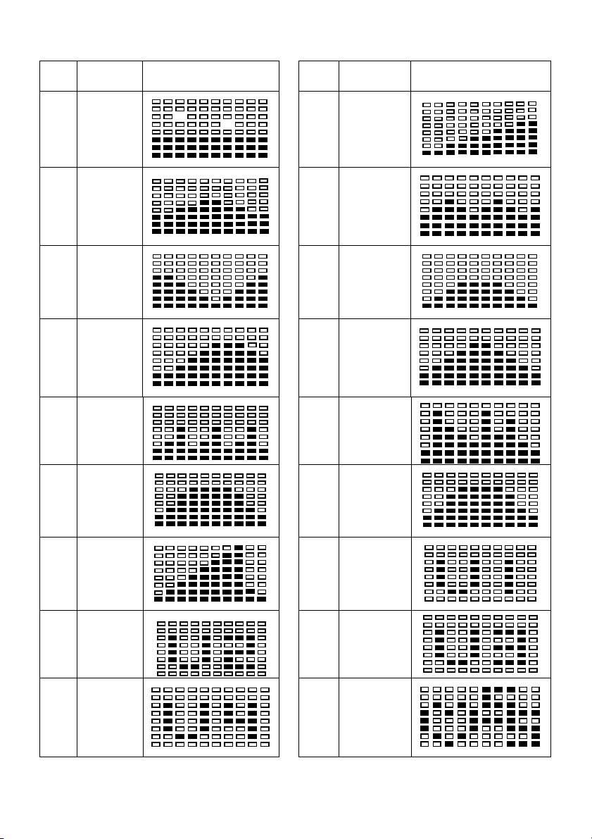
LCD Work out Gr aph ics
P#
Program
Display
P#
Program
Display
P1
Manual
P2
Steps
P3
Hill
P4
Rolling
P5
Val ley
P6
Fat Bur n
P7
Ramp
P8
Mountain
P9 Internals
P10 Random
P11
Plateau
P12
Far tlek
P13
Precipice
P14
User 1
P15
User 2
P16
User 3
P17
User 4
P18
55%
H.R.C.
22
Page 23
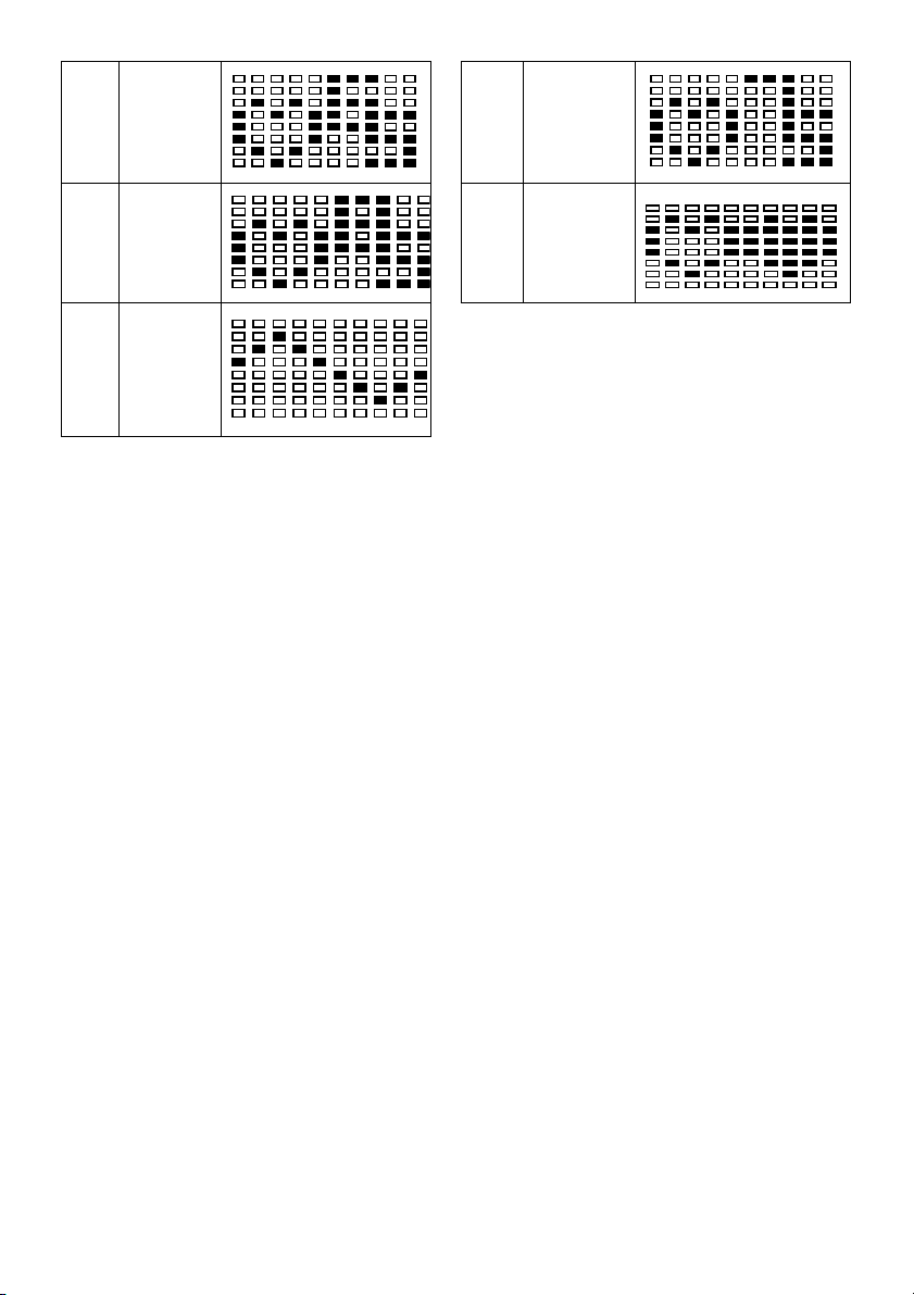
P19
65%
H.R.C.
P20
75%
H.R.C.
P21
85%
H.R.C.
P22
Ta r g e t
H.R.C.
P23
Body Fat
(Stop
Mode)
Error Messages
E1 (ERROR 1):
• Normal state: During workout, when the monitor did not get the count signal from
the gear motor more than 4 seconds and check under successive 3 times then the
LCD will show E1.
• Power on state: The gear motor will return to zero automatically, when the signal of
motor cannot be detected for more than 4 seconds then the gear motor’s driver will
be cut off immediately and show the E1 on the LCD display. All the other digital and
function mark are blank, and the output signals are cut off also.
E2:
When the monitor read the memory data, if the I.D. code is not correct or the memory IC
damages then the monitor will show E2 immediately at power on.
E3:
After 4 seconds by start mode, the computer detects the faulty motor did not leave the zero
point then the LCD bar displays “E3”.
23
Page 24

Need more information?
We hope that this user guide has given you
the assistance needed for a simple set-up.
For the most up-to-date guide for your product,
as well as any additional assistance you may require,
head online to help.kogan.com
24
 Loading...