

Fortis Frinvsntbla User Manual

FRINVSNTBLA
Fortis Inversion Table
Quick Start Guide
Table of Contents
Safety & Warnings..................................................................................................................1
List of Parts.............................................................................................................................2
Assembly.................................................................................................................................3
Operation.................................................................................................................................5
Safety & Warnings
• As with all exercise equipment, you should consult your physician or other
health care professional before using this machine or beginning an exercise
regime.
• Read these instructions in full before first use and retain for future reference.
• If any time you feel weak or dizziness while operating the equipment, stop
exercise immediately. You should also stop exercising if you are experiencing
pain or pressure.
• Wait a while after eating before using machine. If you get nauseous, come up
as soon as you feel queasy.
• Keep children and pets away from the equipment while in use.
• Only one person should use the equipment at a time.
• Make sure your equipment is correctly assembled before you use it. Be sure
all screws, nuts, and bolts are tightened prior to use.
• Do not operate this or any exercise equipment if it is damaged.
• Always use this equipment on a clear and level surface. Do not use outdoors
or near water.
• Keep hands and feet away from any moving parts. Do not insert any object
into any openings.
• Keep loose clothes and jewellery away from moving parts.
WARNING: Before using this equipment, you should consult with your personal
physician to see if inversion equipment is appropriate for you. Do not use this
equipment without your physician's approval. Do not use this equipment if you
have any of the following conditions or ailments:
• Obesity
• Glaucoma, retinal detachment or conjunctivitis
• Pregnancy
• Spinal injury, cerebral sclerosis, or acutely swollen joints
• Middle ear infection
• High blood pressure, hypertension, recent stroke or transient ischemic attack
• Heart or circulatory disorders for which you are being treated
• Hiatus hernia or ventral hernia
• Bone weaknesses including osteoporosis, unhealed fractures, modularly pins,
or surgically-implanted orthopedic supports.
• Use of anti-coagulants including aspirin in high doses.
1
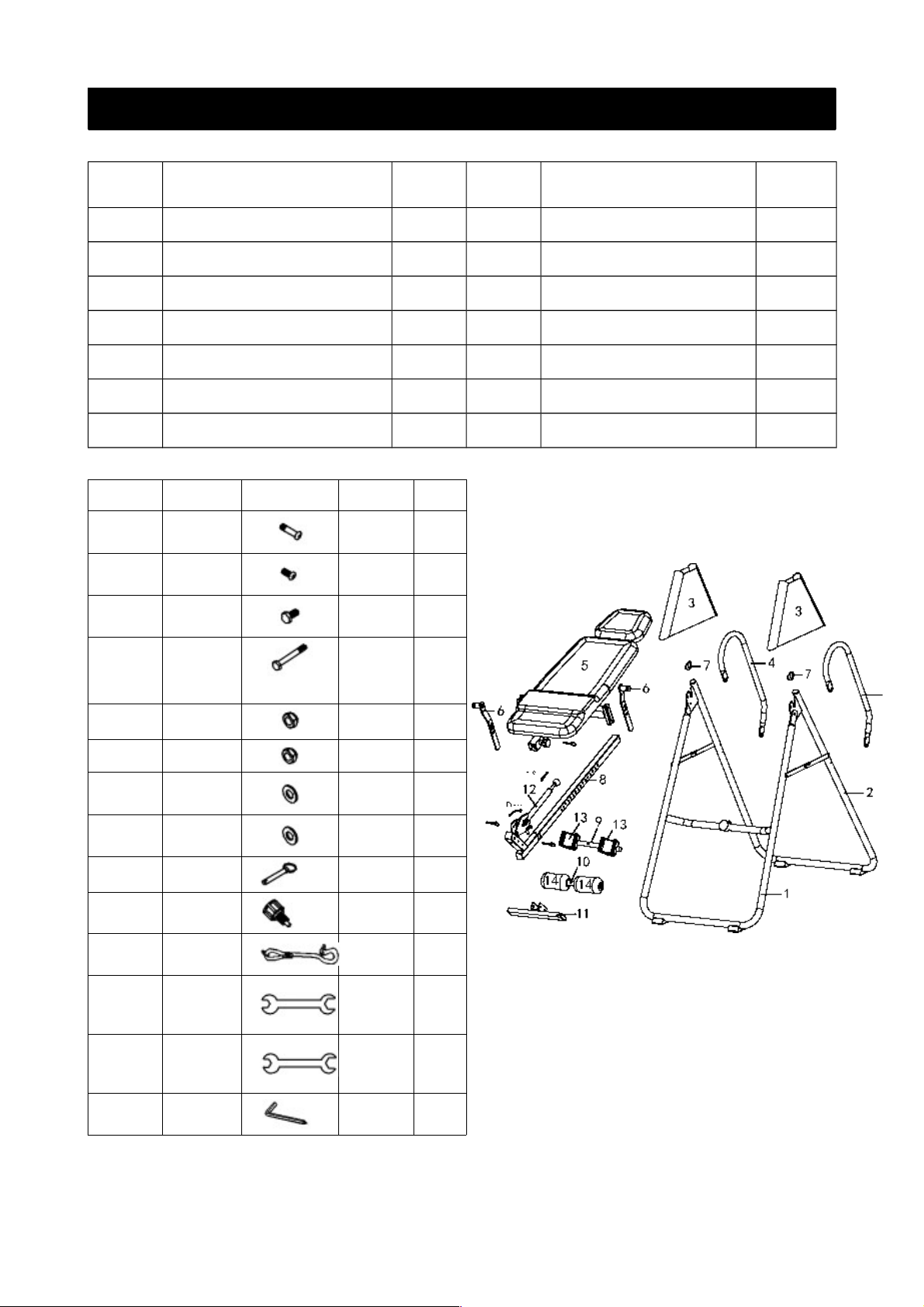
List of Parts
PART NAME QTY PART NAME QTY
1 Front U-Frame 1 8 Height Adjustable Beam
1
2 Rear U-Frame 1 9 Up Foot Holder Rod
1
3 Protective Cover 2 10 Adjustable Instep Frame
1
4 Foam Grip 2 11 Footrest
1
5 Bed Frame 1 12 Foot Adjustment Rod
1
6 Pivot ARM 2 13 Foam Pad
2
7 Safety Bracket 2 14 Heel Holder
2
PART NAME PICTURE SIZE QTY
15
Philips
Screw
M8*45 2
16
Philips
Screw
M8*20 2
17
Hex Head
bolt
M8*16 1
18
Hex Head
bolt
M8*55 2
19 Lock Nut M10 1
20 Lock Nut M8 8
21 Washer
∮8.5* 16*∮
1.2
13
22 Washer
∮10.5* 20∮
*1.2
1
23 TAB bolt ∮8*55 2
24 Knob M16*20 1
25
Safety
Strap
1
26
Double
open
wrench
13#-17# 1
27
Double
open
wrench
14#-17# 1
28
Screw
driver
5# 1
2
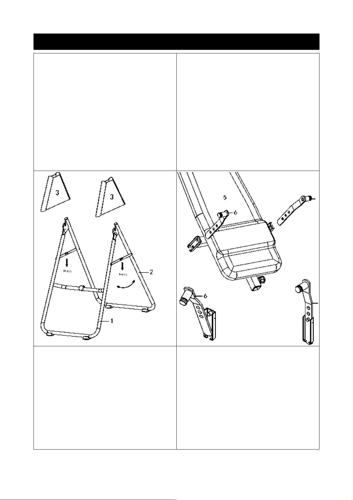
Assembly
Step 1.
A. Stand the base of the machine by
separating the U-frames (1,2). Pull the Front
and Rear U-Frames (1,2) as far apart from each
other as possible. Then push down on the
middle of the two Folding Arms until they are
fully locked down.
B. Slide one Protective Cover (3) on to each
side of the base, as shown: pull down on the
covers until the bottom of the Covers are
slightly lower than the Folding Arms. Use the
Velcro straps on the bottom of the covers to
secure the Covers to the Folding Arms. When
the covers are assembled correctly, the folding
arms should be fully covered by the protective
cover.
Step 2.
Slide the bottom of the Pivot Arms (6) into
the brackets located at each side of the Bed
Frame(5). Align to the desired hole on the arm
with the peg on the bracket. Insert the peg
into the hole to lock the pivot arm in place. It
is recommended that you use the bottom hole
on the pivot arm until you become more
familiar with the equipment.
Step 3.
Attach the safety bracket (7) to the Pivot ARM
(6).
B. Mount the Frame to the Rear U-Frame (2)
by inserting the ends of the Pivot Arms (6)
into the channels on the plates. The slotted
portion of the rollers, on the end of the Pivot
arms, should be inserted into the channels on
the plates.
C. Attach the Rear U-Frame(2) and Foam Grip
(4) by using Hex Head Bolt (16,15). Fix Washer
(21) and Lock Nut (20 & 21) as per diagram.
Step 4.
A. Put the Up foot holder rod (9) through the
large hole of the Height Adjustable Beam(8):
both sides should be the same length. Lock
with screw (16) and Washer (21) on the Height
Adjustable Beam (8). Now, attach one Heel
Holder (14) to one end of the Rod (9). Do trhe
same on the other end of the rod.
B. Attach the adjustable instep Frame (10)
from down to up with the Foot Adjustment
Rod (12) b using Washer (22) and Lock Nut
(19).
3
 Loading...