

Page 1
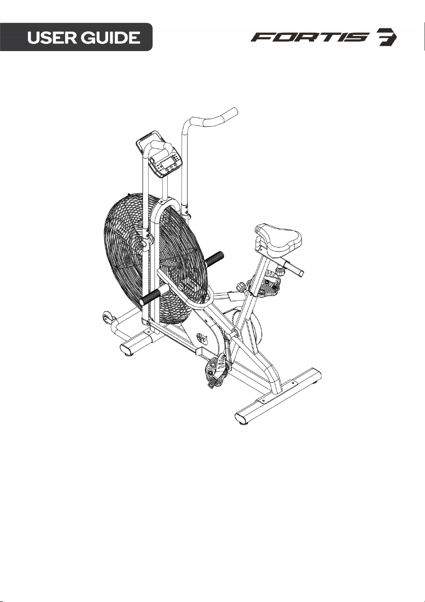
27" FAN RESISTANCE
EXERCISE AIR BIKE
(AEXR-270)
FSFNARBK27A
Page 2

Page 3

SAFETY & WARNINGS
• Read all of the instructions in this guide before using this product. Retain this guide
for future reference. Do not skip, substitute or modify any steps or procedures in this
guide, as doing so could result in personal injury or product damage.
• Before starting any exercise program, consult your physician to determine if you
have any medical or physical conditions that could put your health and safety at
risk or prevent you from using the equipment properly. Your physician’s advice is
essential if you are taking any medication that may affect your heart rate, blood
pressure or cholesterol level.
• Incorrect or excessive exercise can damage your health. Stop exercising if you
experience any of the following symptoms: pain, tightness in your chest, irregular
heartbeat, shortness of breath, light headedness, dizziness or feelings of nausea. If
you experience any of these conditions, you should consult your physician before
continuing with your exercise program.
• This equipment is intended for adult use only. Keep children and pets away from
the machine. DO NOT leave children unattended in the same room with the
equipment.
• This appliance is designed for consumer use. Follow directions and use only as
described.
• Once fully assembled, inspect to ensure all hardware parts such as bolts, nuts and
washers are positioned correctly and tightly secured.
• Always inspect the safety chain guard that protects the moving parts of the bike to
be in safe and good order.
• Always inspect the seat, seat slider and grips to make sure they are in safe and
stable position before using the bike.
• It is recommended to lubricate all moving parts on a monthly basis.
• Do not wear loose clothing while riding.
• Dry after each use to remove moisture. Wipe regularly with a mild, non-abrasive
cleaner and water solution. To avoid damaging the finish, never use a petroleumbased solvent.
• Use the equipment on a solid, flat level surface with a protective cover for your floor
or carpet. To ensure safety, the equipment should have at least 2 feet
(approximately 60 cm) of free space on each side.
• Prior to assembly, ensure you have all the components and tools listed. Some
components are pre-assembled to help with the assembly process.
• Always use the equipment as intended. If you find any defective components while
assembling or checking the equipment, or if you hear any unusual noises coming
from the equipment during exercise, cease use immediately and contact
help.kogan.com for assistance. Do not use until resolved.
• Do not place fingers or any other objects into moving parts of the exercise
equipment.
Page 4

• Do not exceed the maximum user weight of 120 KG.
• Be careful when lifting and moving the equipment. Always use proper lifting
technique and seek assistance if necessary.
• Yo ur e qu i p me n t is i nt e n de d fo r us e in cool, dry conditions. You should avoid storage
in extreme cold, hot or damp areas as this may lead to corrosion and other related
problems.
• Operating temperature: 0 - 40 °C
• Storage temperature: -10 - 60°C
• This appliance contains no user-serviceable parts. If it suffers any failure or
damage, cease use immediately and contact help.kogan.com
• This equipment is designed and intended for indoor use only.
• Be careful when step on or leave the pedal always hold the handlebars first. Ensure
the pedal at your side is at the lowest position, stand on the pedal and step over
the main frame then step on the other pedal.
Page 5
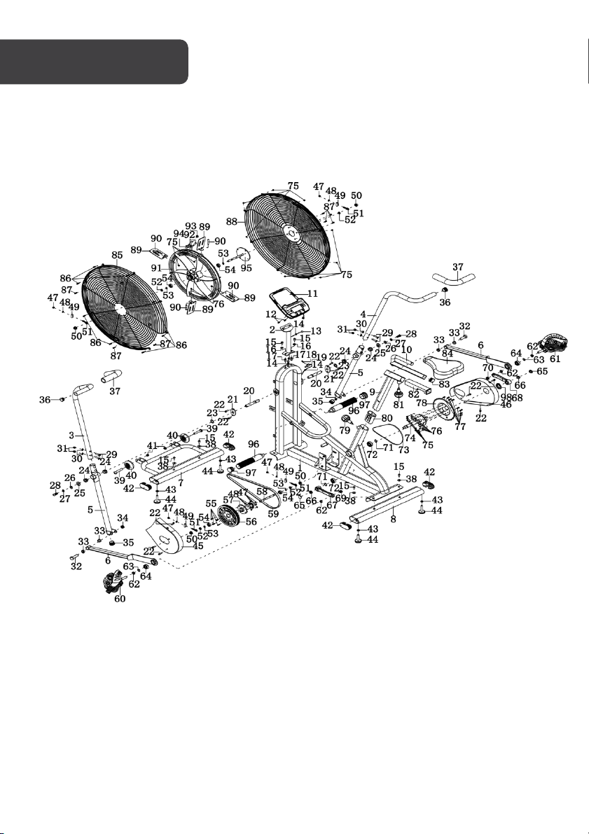
OVERVIEW
Page 6
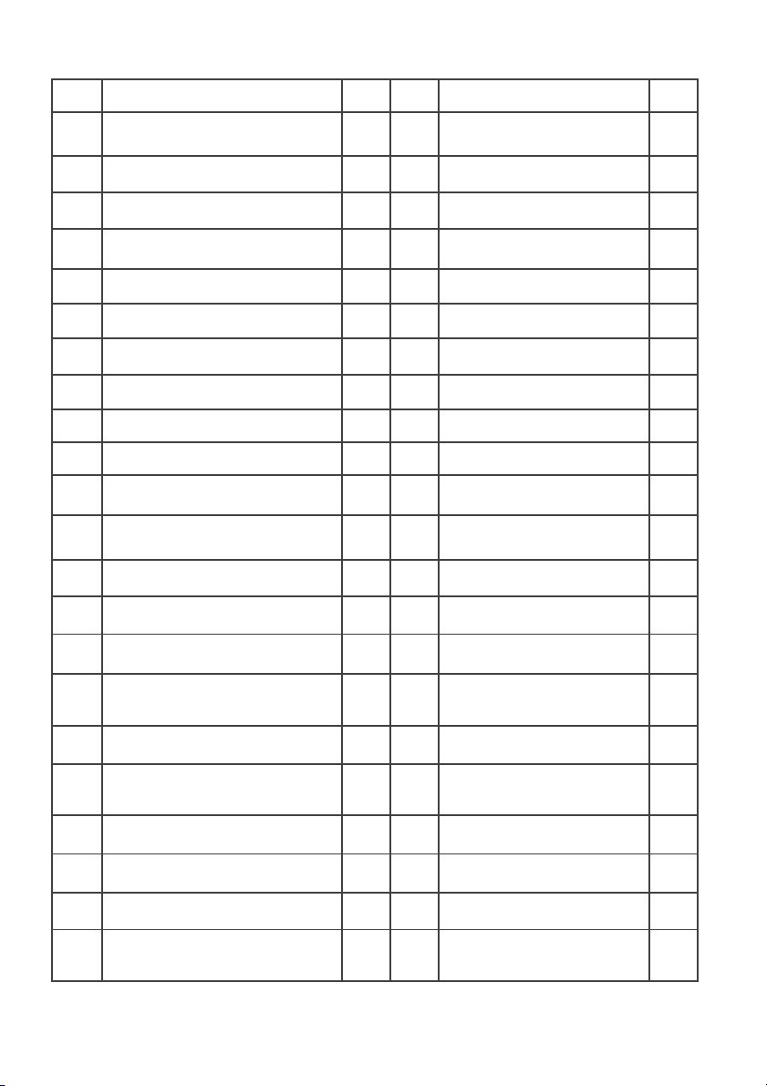
Part List
No.
Description
Qty
No.
Description
Qty
1
Main Frame
1
23
Wave Washer
Ø26xØ16x0.3
2
2
Meter Post
1
24
Metal Bushing
Ø28xØ16x16
4
3
Left Handrail Arm
1
25
D-shaped Washer
Ø28xØ16x5
2
4
Right Handrail Arm
1
26
Flat Washer Ø10xØ25x2.0
2
5
Handrail
2
27
Spring Washer
Ø19.5xØ11.5x3.0
2
6
Left and Right Foot Bar
2
28
Hexagon Bolt M10x20
2
7
Front Stabilizer
1
29
Carriage Bolt M8 x 40
4
8
Rear Stabilizer
1
30
Curve Washer
Ø
20xØ8x1.5
4
9
Seat Post
1
31
Cap Nut M8
4
10
Seat Slider
1
32
Hexagon Bolt M10x50
2
11
Display
1
33
Metal Bushing Ø24x15
4
12
Cross Pan Head Screw M5x10
2
34
Nylon Nut M10
2
13
Extension Sensor Wire
1
35
End Cap Ø32
2
14
Wire Plug Ø12
3
36
End Cap Ø28
2
15
Hexagon Bolt M8x16
6
37
Handrail Arm Foam Grip
2
16
Curve Washer Ø16xØ8x1.5
2
38
Flat Washer Ø20xØ8x1.5
4
17
Nut M8
2
39
Hexagon Bolt M8x40
2
18
Cross Pan Head Self-Drilling
Tapping Screw ST4.2x20
1
40
Movable Wheel
2
19
Senor Wire
1
41
Nylon Nut M8
2
20
Axle 2 42
End Cap for Front and
Rear Stabilizer 80x40
4
21
Locking Plate
2
43
Hexagon Nut M10
4
22
Bolt M6x10
10
44
Cushion
4
Page 7
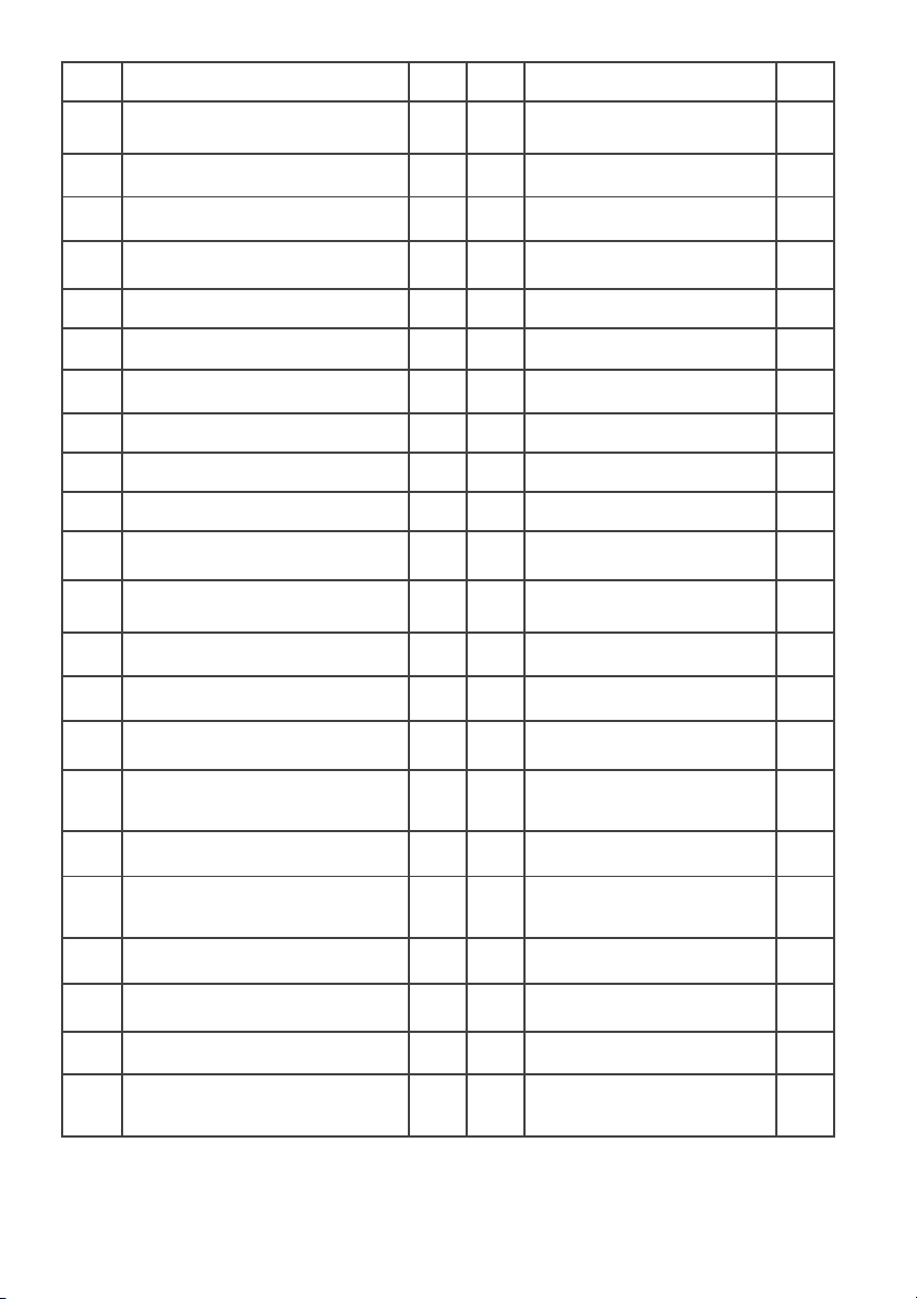
No.
Description
Qty
No.
Description
Qty
45
Left Chain Cover
1
67
Left Crank
1
46
Right Chain Cover
1
68
Right Crank
1
47
Hexagon Nut M6
8
69
Left Nylon Nut 1/2"
1
48
Spring Washer Ø6
8
70
Right Nylon Nut 1/2"
1
49
Tension Bracket
4
71
Ring Ø20
2
50
Flange Nut M10x1.0
4
72
Bearing 6004Z
2
51
Eye Bolt M6x36
4
73
Chain
1
52
Hexagon Nut M10x1.0
4
74
Magnetic Wheel Axle
1
53
Ring Ø10
4
75
Hexagon Nut M5
22
54
Bearing 6003Z
4
76
Spring Washer Ø5
8
55
Hexagon Bolt M6x15
4
77
Hexagon Bolt M5x15
8
56
Belt Pulley
1
78
Chain Pulley
1
57
Gear Ø18xØ13x6
1
79
Seat Height Adjustment
Knob M16x25
1
58
Fan Wheel Axle Ø10x140
1
80
Plastic Bushing
1
59
Belt 1 81
Adjustment Knob M16x35
1
60
Left Foot Pedal
1
82
Seat Post Plastic Bushing
1
61
Right Foot Pedal
1
83
End Cap 30x30
1
62
Spacer
4
84
Seat Cushion
1
63
Ring Ø32
2
85
Left Flywheel Cover
1
64
Bearing Ø32xØ13x10
2
86
Cross Pan Head Bolt
M5x10
8
65
Crank Cover
2
87
Screw M6x10
7
66
Flange Nut M10x1.25
2
88
Right Flywheel Cover
1
Page 8
No.
Description
Qty
No.
Description
Qty
89
Blade
4
94
Sensor Holder
1
90
Bolt M5x40
4
95
Fan Wheel Axle
1
91
Fly Wheel
1
96
Footrest
2
92
Bolt M5x35
2
97
End Cap Ø38
2
93
Magnet
1
98
Crank Cap
1
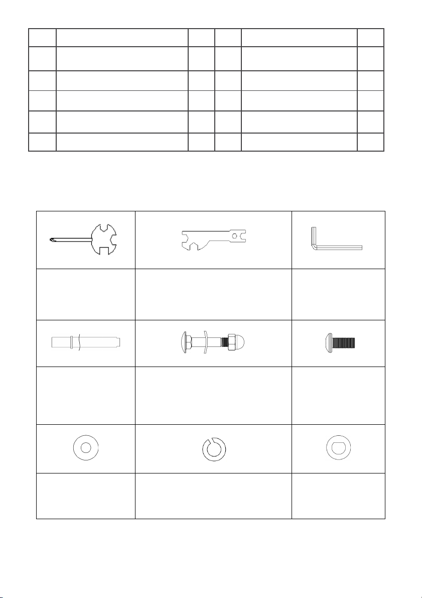
Spanner with Phillips
Screwdriver
S13-S14-S15 (1PC)
Spanner
S10-S13-S17-S19 (1PC)
Allen Wrench S6
Allen Wrench S5
(20) Axle 2PCS
(23) Wave Washer
ø26xø16x0.3 (2PCS)
(29) Carriage Bolt M8×40 (4PCS)
(30) Curve Washer ø20xø8x1.5 (4PCS)
(31) Cap Nut M8 (4PCS)
(28) Bolt M10x20
(2PCS)
(26) Washer
ø10xø25x2.0 (2PCS)
(27) Spring Washer ø19.5xø11.5x3
(2PCS)
(25) D-shaped
Washer Ø28xø16x5
(2PCS)
Hardware & Tools
Page 9
Allen Wrench S6
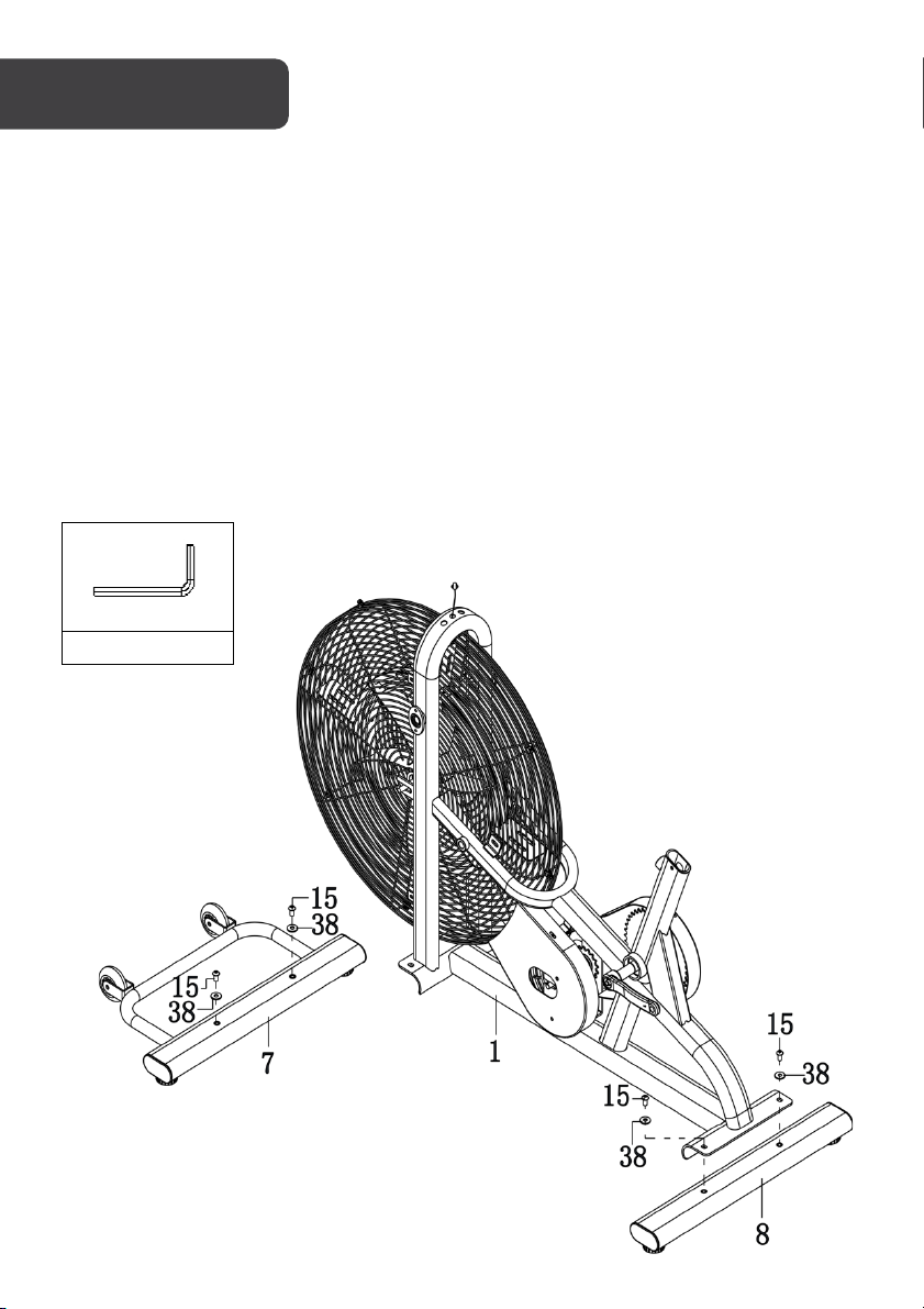
Step 1: Fr on t a nd R ear S ta bil iz er I nst al la ti on
• Remove x2 M8x16 Hexagon Bolts (15) and x2 Ø20xØ8x1.5 Flat Washers (38) from
the Front Sta biliz er (7) using the S6 Allen Wrench provided.
• Attach the Front Stabilizer (7) onto the Main Frame (1) with removed the x2 M8x16
Hexagon Bolts (15) and x2 Ø20xØ8x1.5 Flat Washers (38). Tighten using the S6
Allen Wrench provided.
• Remove x2 M8x16 Hexagon Bolts (15) and two Ø20xØ8x1.5 Flat Washers (38) from
the Rear Stabilizer (8) using the S6 Allen Wrench provided.
• Attach the Rear Stabilizer (8) onto the Main Frame (1) with x2 M8x16 Hexagon Bolts
(15) and x2 Ø20xØ8x1.5 Flat Washers that were removed (38). Tighten bolts using
the S6 Allen Wrench provided.
To o ls
Page 10

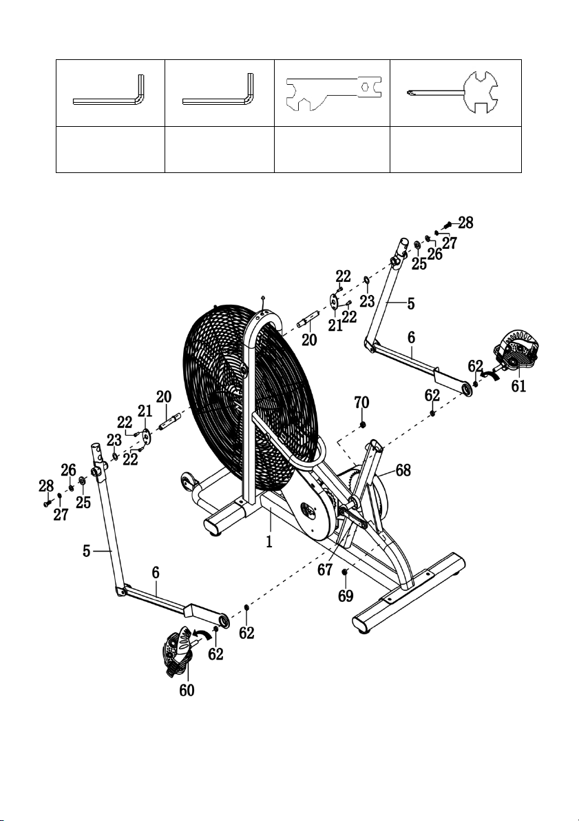
Step 2: Handrail, Foot Bar and Foot Pedal Installation
Note:
Do not turn the Left pedal clockwise to tighten or will strip the threads.
• Remove x4 M6x10 Bolts (22) from the Main Frame (1) and take out x2 Locking
Plates (21).
• Install the Axle (20) to the Main Frame (1), tighten with Spanner provided.
• Then attach x2 Locking Plates (21) to the Axle (20) with removed x4 M6x10 Bolts
(22). Tighten using the Allen Wrench S5 provided.
• Assemble the Handrail (5) to the Main Frame (1) with x2 Ø26xØ16x0.3 Wave
Washers (23), x2 Ø28xØ16x5 D-shaped Washers (25), x2 Ø10xØ25x2.0 Flat
Washers (26), x2 Ø19.5xØ11.5x3.0 Spring Washers (27) and x2 M10x20 Hexagon
Bolts (28). Tighten using the Allen Wrench S6 provided.
• Remove the Spacer (62) and Right Nylon Nut (70) from the Right Foot Pedal (61) .
Attach the Right Foot Bar (6) onto the right Crank (68) using Right Foot Pedal (61),
the Spacer (62) and Right Nylon Nut (70).
• Tighten the Right Foot Pedal (61) by hand clockwise with spanner with Phillips
Screwdriver provided and tighten the Right Nylon Nut (70) counter-clockwise using
the Spanner provided.
• Repeat the same procedure to attach the Left Foot Bar (6) onto the left Crank,
tighten the Left Foot Pedal (60) counter-clockwise with spanner with Phillips
Screwdriver provided and tighten the Left Nylon Nut (69) clockwise using the
Spanner provided.
Page 11
To o l s :
Allen Wrench S5
Allen Wrench S6
Spanner
S10-S13-S17-S19
Spanner with Phillips
Screwdriver
S13-S14-S15
Page 12
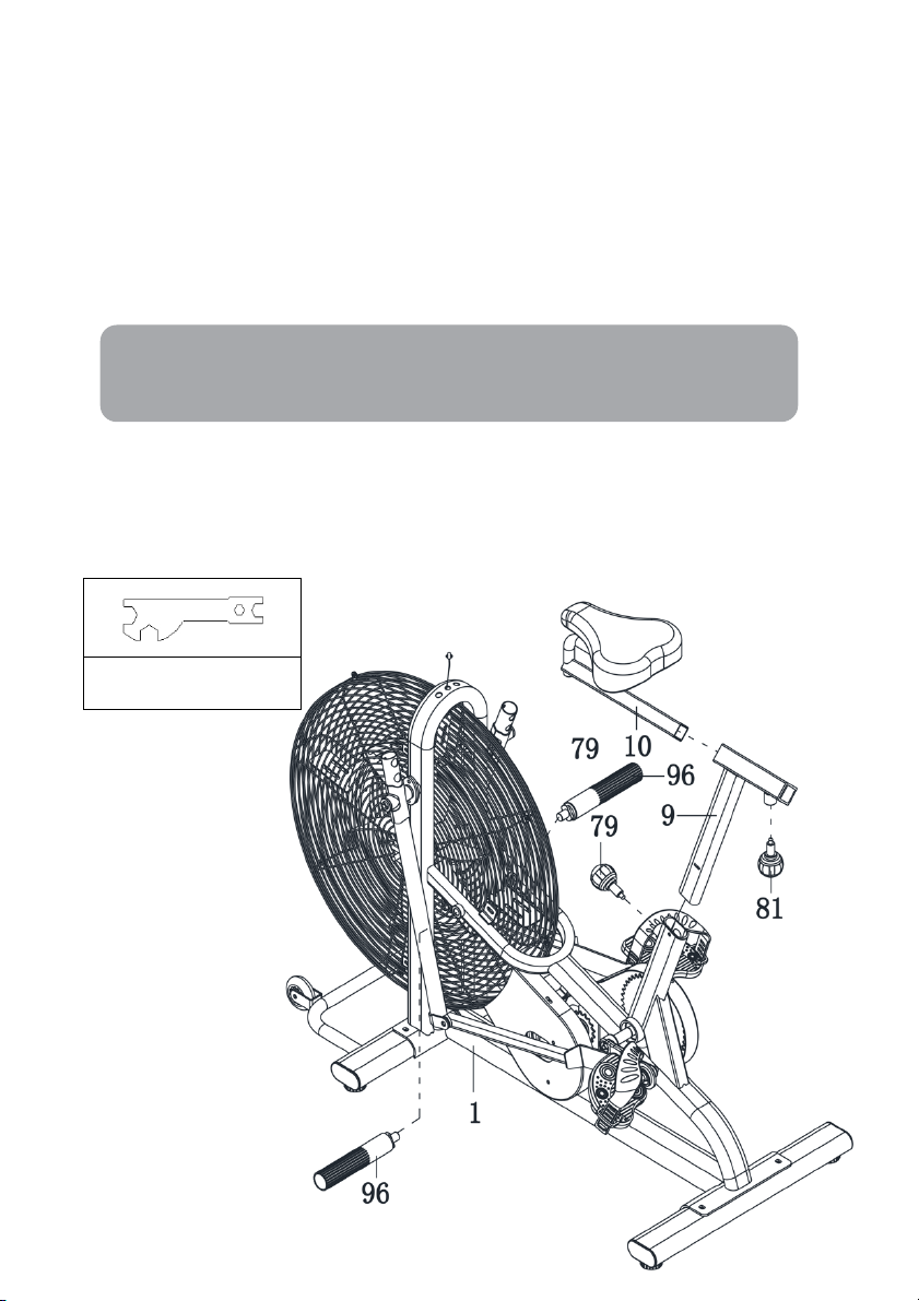
Step 3: Seat Post, Footrest Installation
Spanner S10-S13-S17-
S19
Note:
When adjusting the height of Seat Post, make sure the Plastic Bushing does
not Exceed the mark line on the Seat Post.
• Tu r n t h e M 1 6 x 3 5 A d j u s t m e n t K n o b (81) from the Seat Post (9) in a counter
clockwise direction to release the Seat Slider (10). Then adjust the Seat Slider (10)
back or forth slightly to the desired hole for the suitable position.
• Lock the Seat Slider (10) in place by tightening M16x35 Adjustment Knob (81) in a
clockwise direction.
• To a d j u s t t h e s e a t h e i g h t , l o o s e n t h e M 1 6 x 2 5 S e a t H e i g h t A d j u s t m e n t K n o b (79) on
the vertical post stem on the Main Frame and pull back the Knob. Position the
vertical seat post for the desired height so that holes are aligned, then release the
knob and retighten it.
• Attach the Footrest (96) onto the Main Frame (1). Tighten using the Spanner
provided.
To o l s:
Page 13

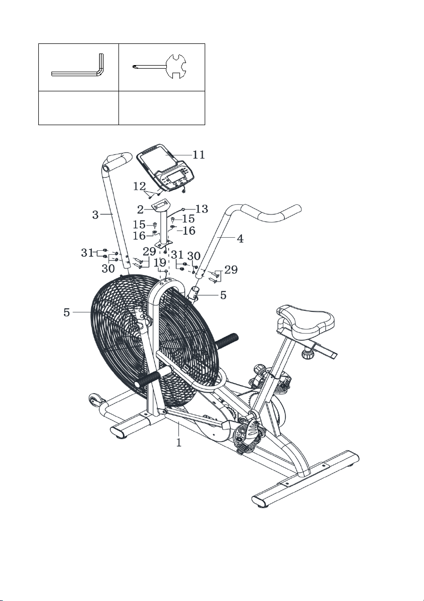
Step 4: Left and Right Handrail Arm, Meter Post Installation
• Insert the Right Handrail Arm (4) on the tube of the Right Handrail (5) with x2
M8x40 Carriage Bolts (29), x2 Ø20xØ8x1.5 Curve Washers (30) and x2 M8 Cap
Nuts (31).
• Repeat the same procedure to assemble the Left Handrail Arm (3).
• Connect the Sensor Wire (19) with the Extension Sensor Wire (13).
• Remove x2 M8x16 Hexagon Bolt (15) and x2 Ø16xØ8x1.5 Curve Washers (16) from
the Main Frame (1).
• Attach the Meter Post (2) onto Main Frame (1) with removed x2 M8x16 Hexagon
Bolt (15) and x2 Ø16xØ8x1.5 Curve Washers (16). Tighten using the Allen Wrench
provided.
• Remove x2 M5x10 Cross Pan Head Screws (12) from the Display (11).
• Then attach the Display (11) onto the top end of Meter Post (2) with x2 removed
M5x10 Cross Pan Head Screws (12). Tighten screws using the Spanner with Phillips
Screwdriver provided. Connect the Meter Wire (11) with the Middle Wire (13).
Page 14
To o l s :
Allen Wrench S6
Spanner with
Phillips Screwdriver
S13-S14-S15
Page 15

BUTTONS
Mode: Press this button to changeover display or choose the window needs to be set.
Set: In setting status, press this button to increase setting value in relevant flashing window
for TIME, DIST, and CAL.
Reset:
• In setting status, press this button to reset the value in relevant flashing window for
TIME, DIST and CAL, PULSE.
• In monitor status, hold this button for 3 seconds to reset all value to zero.
FUNCTIONAL AND OPERATIONS
Scan: Press MODE button until “SCAN” appears, the Display will rotate through all the 5
functions: Time, Speed, Distance, Calorie and pulse. Each display will be held for 5 seconds.
Time:
• Count the total time from exercise start to the end and the range is 0 ~ 99 minutes
• Exercise time can be set in advance, when it approaches the preset time, the
monitor will alarm 4 seconds. The maximum pre-set time is 99 minutes.
Speed: Display instantaneous speed and the range is 0.0~999.9km/h.
Distance:
• Count the total distance from exercise start to the end and the range is 0.0 ~
999.9km.
• Exercise distance can be set in advance, when it approaches the preset distance,
the monitor will alarm 4 seconds. The maximum pre-set distance is 999.0km.
Speed: Display instantaneous speed and the range is 0.0~999.9km/h.
Calories:
• Count the total calories consumed from exercise start to the end and the range is
0.0 ~ 999.9 KCA L.
• The calorie value can be set in advance, when it approaches the preset calorie, the
monitor will alarm 4 seconds. The maximum pre-set calories are 999.0KCAL.
ODO: Display the total accumulated distance travelled
AUTO START/STOP
• Without any signal of exercise or operation for 4 minutes, the power will turn off
automatically.
• Once receive exercise or operation signal, the monitor will turn on automatically.
Page 16

Need more information?
We hope that this user guide has given you
the assistance needed for a simple set-up.
For th e mo st u p-to-date guide for your product,
as well as any additional assistance you may require,
head online to help.kogan.com.
 Loading...