

Page 1
© Copyright 2007 Fortinet Incorporated. All rights reserved.
Products mentioned in this document are trademarks or registered trademarks of their respective holders.
Regulatory Compliance
FCC Class A Part 15 CSA/CUS
13 July 2007
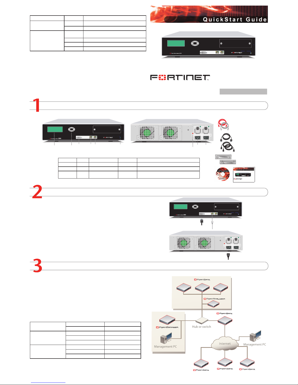
Checking the Package Contents
Connecting
Planning the Configuration
1
CONSOLE
2
PWE
Back
Front
Ether net C ables :
Orang e - C rosso ver
Gray - Str aight -thro ugh
Power Cable s (2)
Power Conne ction
Alarm Cance l But ton
DB-9 C onsol e Cab le
Mounti ng Br acket s (2)
1
CONSOLE
2
PWE
Docume ntation
FortiManager 300 0
Copyright 2006 Fortinet I ncorporated . All right s reserved.
Trademarks
Products mentioned in thi s document are tradema rks.
Qu i ck S ta r t G u id e
1
CONSOLE
2
PWE
LCD Pa nel
Serial
Consol e
Port
1 and 2
Contro l
Button s
Power
Light
Straigh t-through E thernet cab le connects
to hub or switch o n the netwo rk
Optiona l null mode m cable con nects
to seri al port on management computer
Power c able connec ts to power outlet
1
CONSOLE
2
PWE
Connector Type Speed Protocol Description
Port 1 RJ-45 100/1000 Base-T Ethernet Connection to the network
Port 2 RJ-45 100/1000 Base-T Ethernet Connection to the network.
CONSOLE DB-9 9600 bps RS-232 serial Optional connection to the management computer.
Provides access to the command line interface (CLI).
Place the unit on a stable surface. It requires 1.5 inches (3.75 cm) clearance above and
on each side to allow for cooling.
Alternatively, Mount the unit in a standard 19-inch rack. The FortiManager 400 system
requires 1 U of vertical space in the rack.
Connect the network cable to interface 1.
•
•
•
Connect the FortiManager System to a power outlet and to the internal and external networks.
FortiManager 3000
02-30005-0241-20070713
FortiManager Server LED Indicators
LED State Description
Power
Green The FortiManager Server unit is powered on.
Off The FortiManager Server unit is powered off.
All Ports
Amber The correct cable is in use and the connected equip-
ment has power.
Flashing Network activity at this interface.
Green The interface is connected at 1000 Mbps.
Off The interface is connected at 100 Mbps.
To power up the FortiManager Server, connect the power cables to the power outlets.
After a few seconds, SYSTEM STARTING appears on the LCD. The menu selections appear
when the unit is up and running.
If you connect only one power source, an audible alarm sounds to indicate a failed power
supply. To stop this alarm, press the red alarm cancel button on the rear panel next to the
power supply inputs.
The FortiManager System is an integrated management and monitoring tool that consists of
one or more FortiManager Servers and managed FortiGate and FortiAnalyzer devices.
The FortiManager Server manages communication between FortiGate devices, and a
FortiAnalyzer device. The FortiManager Server stores and manages all FortiGate device
congurations. It can also act as an on-site FDN server for the FortiGate devices to download virus and attack signatures, and to use the web ltering and antispam service. The
FortiManager Server can also connect to a FortiAnalyzer unit for managing and monitoring
logs and reports for all managed FortiGate devices.
Factory Defaults
Administrator Account
User name: admin
Password: (none)
Port 1
IP: 192.168.1.99
Netmask: 255.255.255.0
Management Access: ping, https, http, ssh
Port 2
IP: 0.0.0.0
Netmask: 0.0.0.0
Management Access:
Page 2
Completing the Configuration
Congratulations!
You have nished conguring the basic settings. You are now ready to add and manage
FortiGate devices. To explore the full range of conguration options, see the online help or
the Tools and Documentation CD.
Visit these links for more information and documentation for your Fortinet product.
Technical Documentation - http://docs.forticare.com
Fortinet Knowledge Center - http://kc.forticare.com
Fortinet Technical Support - http://support.fortinet.com
•
•
•
Configuring the FortiManager Server unit
Web-based Manager
Connect the FortiManager System interface to a management computer Ethernet interface. Use a cross-over Ethernet cable to connect the devices directly. Use straightthrough Ethernet cables to connect the devices through a hub or switch.
Congure the management computer to be on the same subnet as the internal interface of the FortiManager System. To do this, change the IP address of the management computer to 192.168.1.2 and the netmask to 255.255.255.0.
To access the FortiManager System web-based manager, start Internet Explorer and
browse to https://192.168.1.99 (remember to include the “s” in https://).
Type admin in the Name eld and select Login (no password required).
Changing an Administrator Password
To change the administrator password
On the main toolbar, select System Settings.
Go to Administration > Administrators.
Select Edit.
Select Change Password.
Enter and conrm the password.
Select OK.
Conguring the IP Address and Netmask
To congure the IP address
On the main toolbar, select System Settings.
Go to Network > Interface.
Select Edit.
Enter the IP address and netmask.
Select OK.
Conguring the Default Gateway
To congure the default gateway
On the main toolbar, select System Settings.
Go to Network > Routing Table.
Enter the gateway IP address and netmask.
Enter the Destination IP and select the Interface.
Select OK.
Adding a FortiGate unit
Before you can manage a FortiGate unit, you must add it to the Device Manager. Adding an
existing operational device will not result in an immediate connection to the device. Device
connection only happens when you successfully resync the device.
To add a FortiGate device
In the Device Manager, select Device > Add Device from the main toolbar.
Enter the following information and select Discover.
IP Address Enter the IP Address of the device to add.
Discover via Select a method used to nd the device. Currently, only CLI (via
SSH) is supported. By using the CLI (via SSH) Method, Device
Manager is able to record each device being added.
Admin user Select Default (admin) if the device uses the default “admin” as its
admin user.
Select Other and enter the admin user name if the device uses a
different user name other than the default “admin”.
Password Enter the password for the admin user.
The discovery process starts. When it completes, the Add New Device page appears.
Verify the information and add a Description if desired.
Select Add.
Congure the FortiGate unit to be managed through a FortiManager server. Communication between the FortiGate unit and the FortiManager server is via an IPSec VPN that is
invisibly pre-congured on the FortiGate unit.
To congure the FortiGate unit
Log in to the FortiGate unit.
Go to System > Admin > FortiManager.
Complete the conguration and select OK.
1.
2.
3.
4.
1.
2.
3.
4.
5.
6.
1.
2.
3.
4.
5.
1.
2.
3.
4.
5.
1.
2.
3.
4.
1.
2.
3.
Command Line Interface
Use the DB-9 serial cable to connect the FortiManager System Console port to the
management computer serial port.
Start a terminal emulation program (HyperTerminal) on the management computer. Use
these settings:
Baud Rate (bps) 9600, Data bits 8, Parity None, Stop bits 1, and Flow Control None.
At the Login: prompt, type admin and press Enter twice (no password required).
Changing an Administrator Password
To change the administrator password, enter the following commands
cong fmsystem admin user
edit admin
set password <password>
end
Conguring the IP Address and Netmask
To congure the IP address and netmask, enter the following commands
cong fmsystem interface
edit port1
set ip <intf_ip>/<netmask_ip>
end
Conguring the Default Gateway
To congure the default gateway, enter the following commands
cong fmsystem route
edit <route_number>
set device {port1 | port2}
set dst <ip_address>/<netmask_ip>
set gateway <ip_address>
end
Control Buttons and LCD
Use the front control buttons and LCD on the FortiManager Server unit to congure IP addresses, default gateways and console settings without having to go to the command line
interface or the web-based manager.
To congure the FortiManager Server using the control buttons and LCD
Press Enter to access the Main Menu, to select menu items, to move right when entering IP addresses, and to conrm changes.
Press move up and down to navigate the Main Menu, and to change IP address numbers and console baud rate settings.
Press Esc to return to the Main Menu, and to move left when entering IP addresses.
Congure the FortiManager Server IP address and netmask. If the FortiManager Server
connects to a router to reach the Internet, add a default gateway.
Note: When you enter an IP address, the LCD display always shows three digits for each
part of the IP address. For example, the IP address 192.168.100.1 appears on the LCD
display as 192.168.100.001.
1.
2.
3.
4.
•
•
•
•
Choosing a Configuration Tool
Web-based manager
The FortiManager web-based manager is an easy to use management tool.
Use it to congure the administrator password, the interface and default gateway addresses.
Requirements:
An Ethernet connection between the FortiManager Server and management computer.
Internet Explorer 6.0 or higher on the management computer.
Control Buttons and LCD
The control buttons and LCD provide an easy method of setting the interface addresses and
default gateway addresses directly from the front of the FortiManager System without using a
management computer.
•
•
Command Line Interface (CLI)
The CLI is a full-featured management tool. Use it to congure the administrator password,
the interface addresses, the default gateway addresses. To congure advanced settings, see
the Tools and Documentation CD.
Requirements:
The DB-9 serial connection between the FortiManager Server and management computer.
A terminal emulation application (HyperTerminal for Windows) on the management
computer.
•
•
 Loading...