

Page 1
FortiGate-30B
Tools and Documenation
Copyright 2010 Fortinet Incorporated. All rights reserved.
Trademarks
Products mentioned in this document are trademarks.
QuickStart Guide
Straight-through
Ethernet cable
Power cables
DB9-DB9 Console
cable
Rackmount rail kit
i
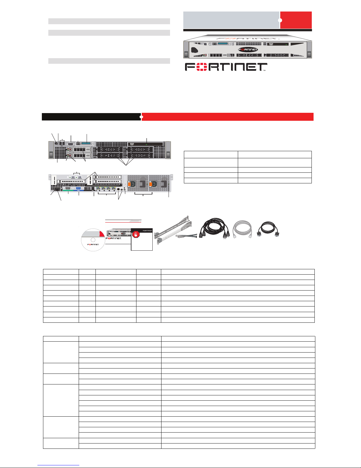
FortiScan 3000C
0►
1►
2►
3►
4►
5►
REGISTER
i
FortiMail 3000C
0►
1►
2►
3►
4►
5►
USB
Ethernet
ports 1-4
Ports 5-6
SFP ports
Power supplies
Video
connector
(not supported)
>
Back
Front
DVD ROM drive
Gb
1
Gb
2
Gb
3
Gb
4
1
3
4
i
2
5
6
I0I0I
Video
connector
Power
button
USB
NMI
button
Info
tag
1 TB Hard
drives
LED menu
buttons
LCD panel
Spare hard
drive slots
Flash
media slot
IDRAC6 port
(not supported)
Serial
connector
System
status
indicators
System
ID button
Power supply
status indicator
PCIe slots
HD activity
LED
HD status
LED
Specifications
For more information
• Documentation CD: all major FortiMail documents
• Fortinet Technical Documentation: http://docs.fortinet.com
• Fortinet Knowledge Base: http://kb.fortinet.com
• Fortinet Technical Support: http://support.fortinet.com
• Fortinet Training Service: http://campus.training.fortinet.com
AC Power 100–240 VAC, 50–60 Hz, 9.0 Amp (Max)
Power Consumption (Average) 200W
Chassis Rack Mount (2U)
Interfaces
4 10/100/1000 Ethernet Base-T
2 SFP 1 GB
4 USB
1 Serial
1 DVD ROM drive
Disk Storage Capacity 6 3.5”x1 TB slots (2x1 TB hard drives provided)
© Copyright 2011 Fortinet Incorporated. All rights reserved.
Trademarks
Products mentioned in this document are trademarks or registered trademarks of
their respective holders.
Regulatory Compliance
FCC Class A Part 15, CE, and UL
Version 4.0 Revision 3
8 April 2011
http://www.fortinet.com
i
FortiMail 3000C
0
►
1
►
2
►
3
►
4
►
5
►
QuickStart Guide
FortiMail-3000C
Interface Description
LED Description
Interface Type Speed Protocol Description
Port 1 to 4 RJ-45 10/100/1000 Base-T Ethernet Connection to the network.
Port 5 to 6 SFP 1 Gbps Ethernet Small form-factor pluggable (SFP) transceiver supports 1 Gbps for SERDES.
Serial DB-9 9600 8/N/1 RS-232 serial Connection to the management computer. Provides access to the CLI console.
USB USB USB For mail data backup and restore in server mode.
Hard drive 1 TB Two hard drives and four spare slots are provided.
iDRAC6 port Port for iDRAC6 enterprise card. This port is not supported.
Flash media slot SD Connection to an SD memory card for the iDRAC6 card. This slot is not supported.
PCIe slots PCIe 500 MB/s Serial Three PCIe Generation 2 expansion slots. Slot 2=x4-link, slot 3=x8-link and slot 4=x8-link.
Video Two video ports that connect to monitors. The video port on the back is not supported.
LED State Description
Power supply
indicator
Off AC power is not connected.
Green Power supply is operational.
Amber Power supply problem.
Blinks green and amber Power supply is mismatched with other power supply.
LCD panel
Blue Normal system operation.
Amber System requires attention. An error code and message is shown.
HD activity LED
Blinking Disk write/read activities.
Off No disk activity.
HD status LED
Green Drive online.
Slow green blinking Drive rebuilding.
Blinks amber 4 times per second Drive failed.
Blinks green, amber, and off Drive predicted failure.
Blinks green 2 times per second Identify drive/prepare for removal.
Off Drive is ready for insertion or removal.
Port 1-4
Activity (right) indicator green flashing Network data is being sent or received.
Link (left) indicator is green Connected at 1000 Mbps.
Link (left) indicator is amber Connected at 10/100 Mbps.
Both LEDs off No connection to the network.
Port 5-6
Green Port is online.
Off Port is offline.
Package Contents
Factory default settings
Default operation mode
Gateway mode
Administrator account
User name: admin
Password: (none)
Default Port 1 IP address 192.168.1.99
Web-based manager URL
https://192.168.1.99/admin
Management access HTTPS, Ping, SSH
Page 2

Deploying the FortiMail unit
Now that the FortiMail unit is up and running, you can start to deploy the unit
into your network by configuring the system settings and mail settings. The
FortiMail Install Guide will help you with this task.
Configuring the FortiMail unit
Then you can configure detailed antispam, antivirus, and logging settings to
protect your mail servers and users. For details, see the FortiMail online help or
the FortiMail Administration Guide on the documentation CD.
Before you can deploy the FortiMail unit, you must connect it to your network.
To do this, use your web browser to connect to the web-based manager. The
web-based manager is a web site on the FortiMail unit that enables you to
change its settings.
The web-based manager has two display modes: Basic and Advanced. The
default when you first log on is Advanced. You can switch between the two
modes by clicking Basic Mode >> or Advanced Mode >>.
In either mode, when connecting for the initial configuration, you can run the
Quick Start Wizard to:
• configure the basic network and antispam settings, and
• initialize default reports
Configuration changes made with the web-based manager are effective
immediately.
To connect to the web-based manager for the first time
1. On your management computer, configure the Ethernet port with the static
IP address 192.168.1.2 and a netmask of 255.255.255.0.
2. Using the Ethernet cable, connect you computer’s Ethernet port to the
FortiMail unit’s port 1.
Use a cross-over Ethernet cable to connect the devices directly. Use
straight-through Ethernet cables to connect the devices through a hub or
switch.
3. Start your web browser, such as Firefox or Internet Explorer with Adobe
Flash Player 10 or greater plug-in, and go to https://192.168.1.99/admin
(include the “s” in https:// and “/admin” after the IP address).
4. Type admin in the Name field and click Login.
5. Go to Monitor > System Status > Status (the dashboard) and set the
Operation mode. The system will log you out and reboot.
The FortiMail unit has three operation modes: gateway, transparent, and
server. For details about operation modes and which mode you should use,
see the FortiMail Install Guide. The default is gateway mode.
6. Log in again.
7. Click Quick Start Wizard to run the configuration wizard. Follow its
directions to configure the basic network and antispam settings.
8. Continue with deployment.
To connect to the CLI
If you prefer to use the CLI, you can connect to it after you have done initial
configuration via the web-based manager’s Quick Start Wizard.
1. Using the null modem or RJ-45-to-DB-9 cable, connect the FortiMail unit’s
console port to the serial communications (COM) port on your management
computer.
2. On your management computer, start a terminal emulator program (such as
HyperTerminal). Use these settings: Bits per second: 9600, Data bits: 8,
Parity: None, Stop bits: 1, Flow control: None.
3. At the login prompt, type admin and press Enter twice.
For CLI commands, or to connect to the CLI through the network, see the
FortiMail CLI Reference.
You can use one of the following tools to configure the FortiMail unit. If you are connecting and using the unit for the first time, it is recommended you use the
web-based manager only, because it comes with a quick start configuration wizard which can guide you through the initial setup.
• Command Line Interface (CLI)
The FortiMail unit has a console port and you can use a console cable to connect it directly to your management computer. For information about CLI
commands, see the FortiMail CLI Reference on the documentation CD.
• Web-based manager
The web-based manager is an easy-to-use management tool that you can access from a web browser.
Powering On
Next Steps
To power on the FortiMail unit
1. Place the FortiMail unit on a stable surface. The unit requires 1.5 inches
(3.75 cm) clearance on each side to allow for cooling.
2. Alternatively install the unit in a 19-inch rack. The unit requires 2U of
vertical space. For detailed instructions, see the FortiMail Install Guide on
the documentation CD.
3. Ensure the power is not connected.
4. Connect the network cable to port 1.
5. Connect the power cable.
6. Turn on the power switch.
Configuring
Configuration Tool Overview
Shutting Down
Installation and configuration of the FortiMail unit involves the following steps:
1. Mounting the unit (optional). See detailed mounting instructions in the
FortiMail Install Guide on the documentation CD.
2. Connecting the unit to the network. For details, see the FortiMail Install
Guide.
3. Powering up the unit. See instructions below.
4. Connecting to the web-based manager. See instructions below.
5. Selecting an operation mode: Gateway, Transparent, or Server. For details,
see the FortiMail Install Guide.
6. Running the QuickStart wizard to configure the basic settings. For details,
see the FortiMail Install Guide.
7. For all other installation instructions, see the FortiMail Install Guide on the
documentation CD.
8. For all the configuration instructions, see the FortiMail Administration Guide
and the FortiMail online help.
9. If you want to use the CLI commands to configure the unit, see the
FortiMail CLI Reference on the documentation CD.
Installation Overview
Always shut down the FortiMail unit properly before turning off the power
switch or removing the power cable to avoid potential hardware problems. This
enables the hard drives to spin down and park correctly and avoid losing data.
To shut down using the web-based manager
1 Go to Management > Status > Status in the basic mode of the web-based
manager, or System > Status > Status in the advanced mode of the web-
based manager.
2 In the System Command widget, select Shutdown.
3 Turn off and/or disconnect the power cables from the power supply.
To shut down using the CLI
Enter the command:
execute shutdown
 Loading...