

Fortinet FortiMail-100, FortiMail-400, FortiMail-100C, FortiMail-2000A, FortiMail-5001A Install Manual
...Page 1

FortiMail™ Secure
Messaging Platform
Version 4.0 Patch 1
Install Guide
Page 2

FortiMail™ Secure Messaging Platform Install Guide
Version 4.0 Patch 1
Revision 2
8 February 2009
© Copyright 2010 Fortinet, Inc. All rights reserved. No part of this publication including text, examples,
diagrams or illustrations may be reproduced, transmitted, or translated in any form or by any means,
electronic, mechanical, manual, optical or otherwise, for any purpose, without prior written permission of
Fortinet, Inc.
Trademarks
Dynamic Threat Prevention System (DTPS), APSecure, FortiASIC, FortiBIOS, FortiBridge, FortiClient,
FortiGate®, FortiGate Unified Threat Management System, FortiGuard®, FortiGuard-Antispam,
FortiGuard-Antivirus, FortiGuard-Intrusion, FortiGuard-Web, FortiLog, FortiAnalyzer, FortiManager,
Fortinet®, FortiOS, FortiPartner, FortiProtect, FortiReporter, FortiResponse, FortiShield, FortiVoIP, and
FortiWiFi are trademarks of Fortinet, Inc. in the United States and/or other countries. The names of actual
companies and products mentioned herein may be the trademarks of their respective owners.
Regulatory compliance
FCC Class A Part 15 CSA/CUS
Caution: Risk of explosion if battery is replaced by incorrect type.
Dispose of used batteries according to instructions.
Page 3

Contents
Contents
Introduction .............................................................................................. 9
Registering your FortiMail unit ...................................................................................... 9
Customer service and technical support...................................................................... 9
Training .......................................................................................................................... 10
Documentation ............................................................................................................. 10
Scope ............................................................................................................................. 10
Conventions .................................................................................................................. 11
Key concepts.......................................................................................... 13
Email protocols ............................................................................................................. 13
SMTP........................................................................................................................ 13
POP3 ........................................................................................................................ 13
IMAP......................................................................................................................... 14
HTTP and HTTPS..................................................................................................... 14
Client-server connections in SMTP............................................................................. 14
MTA .......................................................................................................................... 15
MUA.......................................................................................................................... 15
Incoming vs. outgoing directionality.......................................................................... 15
The role of DNS in email delivery ................................................................................ 16
MX record ................................................................................................................. 17
A record .................................................................................................................... 18
Reverse DNS record................................................................................................. 18
FortiMail web-based manager modes ......................................................................... 19
FortiMail operation modes ........................................................................................... 19
FortiMail high availability modes................................................................................. 19
Hardware installation............................................................................. 21
Cautions and warnings................................................................................................. 21
Grounding................................................................................................................. 21
Rack mount instructions ........................................................................................... 21
Environmental specifications ...................................................................................... 22
Mounting the FortiMail unit .......................................................................................... 22
FortiMail-100 and FortiMail-100C ............................................................................. 22
FortiMail-400............................................................................................................. 22
FortiMail-2000A and FortiMail-4000A....................................................................... 23
FortiMail-2000B ........................................................................................................ 25
FortiMail-5001A ........................................................................................................ 25
FortiMail™ Secure Messaging Platform Version 4.0 Patch 1 Install Guide
Revision 2 3
http://docs.fortinet.com/ • Feedback
Page 4

Contents
Powering on the FortiMail unit..................................................................................... 26
FortiMail-100 and FortiMail-100C ............................................................................. 26
FortiMail-400............................................................................................................. 26
FortiMail-2000A and FortiMail-4000A....................................................................... 26
FortiMail-2000B ........................................................................................................ 27
FortiMail-5001A ........................................................................................................ 27
Connecting to the network........................................................................................ 27
Turning off the FortiMail unit ....................................................................................... 27
Powering off the FortiMail-5001A board ................................................................... 27
Connecting to the web-based manager or CLI........................................................... 28
Connecting to the web-based manager.................................................................... 28
Connecting to the CLI............................................................................................... 29
Using the front panel’s control buttons and LCD display .......................................... 31
FortiMail-2000B hardware installation ................................................. 33
Mounting the FortiMail unit .......................................................................................... 33
Removing the system from the rack ......................................................................... 39
Installing the cable management arm ......................................................................... 40
Installing the hard drives.............................................................................................. 45
Installing the bezel ........................................................................................................ 48
Connecting the keyboard, mouse, and monitor......................................................... 49
Connecting the power cables ...................................................................................... 50
Securing the power cord .............................................................................................. 51
FortiMail-5001A hardware installation ................................................. 53
Changing FortiMail SW11 switch settings.................................................................. 54
FortiMail mounting components ................................................................................. 55
Inserting a FortiMail board ........................................................................................... 56
Removing a FortiMail board......................................................................................... 59
Resetting a FortiMail board.......................................................................................... 61
Troubleshooting............................................................................................................ 61
FortiMail system does not start up............................................................................ 61
FortiMail status LED is flashing during system operation......................................... 61
Updating the firmware ........................................................................... 63
Testing new firmware before installing it ................................................................... 63
Installing firmware ........................................................................................................ 65
Installing backup firmware........................................................................................... 66
Restoring firmware ....................................................................................................... 68
Choosing the operation mode .............................................................. 71
Characteristics of gateway mode ................................................................................ 72
FortiMail™ Secure Messaging Platform Version 4.0 Patch 1 Install Guide
4 Revision 2
http://docs.fortinet.com/ • Feedback
Page 5

Contents
Characteristics of transparent mode .......................................................................... 72
Characteristics of server mode ................................................................................... 73
Configuring the operation mode ................................................................................. 74
Quick Start Wizard ................................................................................. 77
Step 1: Changing the “admin” password ................................................................... 77
Step 2: Configuring the network settings and system time...................................... 78
Step 3: Configuring local host settings ...................................................................... 80
Step 4: Adding protected domains.............................................................................. 82
Step 5: Configuring incoming antispam and antivirus settings............................... 84
Step 6: Configuring access control rules and outgoing antispam and antivirus
settings .......................................................................................................................... 85
Step 7: Reviewing and saving the configuration ....................................................... 88
Continuing the installation........................................................................................... 88
Connecting to FortiGuard services...................................................... 89
Configuring scheduled updates .................................................................................. 91
Configuring push updates ........................................................................................... 92
Manually requesting updates....................................................................................... 94
Gateway mode deployment................................................................... 95
Configuring DNS records ............................................................................................. 95
Configuring DNS records for the protected domains ................................................ 95
Configuring DNS records for the FortiMail unit itself................................................. 96
Configuring a private DNS server ............................................................................. 97
Example 1: FortiMail unit behind a firewall ................................................................ 98
Configuring the firewall ............................................................................................. 99
Configuring the MUAs............................................................................................. 104
Testing the installation............................................................................................ 104
Example 2: FortiMail unit in front of a firewall ......................................................... 104
Configuring the firewall ........................................................................................... 105
Configuring the MUAs............................................................................................. 110
Testing the installation............................................................................................ 110
Example 3: FortiMail unit in DMZ............................................................................... 111
Configuring the firewall ........................................................................................... 112
Configuring the MUAs............................................................................................. 118
Testing the installation............................................................................................ 118
Transparent mode deployment........................................................... 119
Configuring DNS records ........................................................................................... 119
Configuring DNS records for the FortiMail unit itself............................................... 119
Configuring a private DNS server ........................................................................... 121
FortiMail™ Secure Messaging Platform Version 4.0 Patch 1 Install Guide
Revision 2 5
http://docs.fortinet.com/ • Feedback
Page 6

Contents
Example 1: FortiMail unit in front of an email server............................................... 122
Configuring the protected domains and session profiles ........................................ 123
Configuring the proxies and implicit relay ............................................................... 124
Testing the installation............................................................................................ 125
Example 2: FortiMail unit in front of an email hub................................................... 125
Configuring the protected domains and session profiles ........................................ 126
Configuring the proxies and implicit relay ............................................................... 127
Testing the installation............................................................................................ 128
Example 3: FortiMail unit for an ISP or carrier ......................................................... 128
Configuring the connection with the RADIUS server .............................................. 131
Removing the network interfaces from the bridge .................................................. 133
Configuring the session profiles.............................................................................. 134
Configuring the IP-based policies........................................................................... 136
Configuring the outgoing proxy............................................................................... 137
Testing the installation............................................................................................ 138
Server mode deployment .................................................................... 139
Configuring DNS records ........................................................................................... 139
Configuring DNS records for protected domains .................................................... 139
Configuring DNS records for the FortiMail unit itself............................................... 140
Configuring a private DNS server ........................................................................... 141
Example 1: FortiMail unit behind a firewall .............................................................. 142
Configuring the firewall ........................................................................................... 143
Configuring the email user accounts ...................................................................... 146
Configuring the MUAs............................................................................................. 147
Testing the installation............................................................................................ 147
Example 2: FortiMail unit in front of a firewall ......................................................... 147
Configuring the firewall ........................................................................................... 148
Configuring the email user accounts ...................................................................... 150
Configuring the MUAs............................................................................................. 151
Testing the installation............................................................................................ 151
Example 3: FortiMail unit in DMZ............................................................................... 151
Configuring the firewall ........................................................................................... 152
Configuring the email user accounts ...................................................................... 157
Configuring the MUAs............................................................................................. 157
Testing the installation............................................................................................ 157
FortiMail™ Secure Messaging Platform Version 4.0 Patch 1 Install Guide
6 Revision 2
http://docs.fortinet.com/ • Feedback
Page 7

Contents
Testing the installation........................................................................ 159
Troubleshooting tools ................................................................................................ 161
Ping and traceroute ................................................................................................ 161
Nslookup................................................................................................................. 162
Telnet connections to the SMTP port number ........................................................ 163
Log messages ........................................................................................................ 164
Greylist and sender reputation displays.................................................................. 165
Mail queues and quarantines.................................................................................. 165
Packet capture........................................................................................................ 165
Index...................................................................................................... 169
FortiMail™ Secure Messaging Platform Version 4.0 Patch 1 Install Guide
Revision 2 7
http://docs.fortinet.com/ • Feedback
Page 8

Contents
FortiMail™ Secure Messaging Platform Version 4.0 Patch 1 Install Guide
8 Revision 2
http://docs.fortinet.com/ • Feedback
Page 9

Introduction Registering your FortiMail unit
Introduction
Welcome, and thank you for selecting Fortinet products for your network protection.
The FortiMail™ Secure Messaging Platform is an integrated hardware and software
solution that provides powerful and flexible antispam, antivirus, email archiving and
logging capabilities to incoming and outgoing email traffic. FortiMail units have reliable and
high performance features for detecting and blocking spam messages and malicious
attachments.
Built on the Fortinet award winning FortiOS™ and FortiASIC™ technology, the FortiMail
antivirus technology extends full content inspection capabilities to detect the most
advanced email threats.
To ensure up-to-date email protection, FortiMail relies on FortiGuard™ Antivirus and
FortiGuard Antispam security subscription services that are powered by a worldwide 24x7
Global Threat Research Team. FortiMail provides bidirectional email routing, virtualization
and archiving capabilities with a lower total cost of ownership.
This document will assist you in physically connecting and performing required
configuration to achieve a basic FortiMail installation.
This chapter contains the following topics:
• Registering your FortiMail unit
• Customer service and technical support
• Training
• Documentation
• Scope
• Conventions
Registering your FortiMail unit
Before you begin, take a moment to register your Fortinet product at the Fortinet Technical
Support web site, https://support.fortinet.com.
Many Fortinet customer services, such as firmware updates, technical support, and
FortiGuard Antivirus and other FortiGuard services, require product registration.
For more information, see the Fortinet Knowledge Center article Registration Frequently
Asked Questions.
Customer service and technical support
Fortinet Technical Support provides services designed to make sure that your Fortinet
products install quickly, configure easily, and operate reliably in your network.
To learn about the technical support services that Fortinet provides, visit the Fortinet
Technical Support web site at https://support.fortinet.com.
FortiMail™ Secure Messaging Platform Version 4.0 Patch 1 Install Guide
Revision 2 9
http://docs.fortinet.com/ • Feedback
Page 10

Training Introduction
You can dramatically improve the time that it takes to resolve your technical support ticket
by providing your configuration file, a network diagram, and other specific information. For
a list of required information, see the Fortinet Knowledge Center article What does
Fortinet Technical Support require in order to best assist the customer?
Training
Fortinet Training Services provides classes that orient you quickly to your new equipment,
and certifications to verify your knowledge level. Fortinet provides a variety of training
programs to serve the needs of our customers and partners world-wide.
To learn about the training services that Fortinet provides, visit the Fortinet Training
Services web site at http://campus.training.fortinet.com, or email them at
training@fortinet.com.
Documentation
The Fortinet Technical Documentation web site, http://docs.fortinet.com, provides the
most up-to-date versions of Fortinet publications, as well as additional technical
documentation such as technical notes.
In addition to the Fortinet Technical Documentation web site, you can find Fortinet
technical documentation on the Fortinet Tools and Documentation CD, and on the Fortinet
Knowledge Center.
Scope
Fortinet Tools and Documentation CD
Many Fortinet publications are available on the Fortinet Tools and Documentation CD
shipped with your Fortinet product. The documents on this CD are current at shipping
time. For current versions of Fortinet documentation, visit the Fortinet Technical
Documentation web site, http://docs.fortinet.com.
Fortinet Knowledge Center
The Fortinet Knowledge Center provides additional Fortinet technical documentation,
such as troubleshooting and how-to-articles, examples, FAQs, technical notes, a glossary,
and more. Visit the Fortinet Knowledge Center at http://kc.fortinet.com.
Comments on FortiMail technical documentation
Please send information about any errors or omissions in this document to
techdoc_fortimail@fortinet.com.
This document will assist you in physically connecting and using the web-based manager
to perform required configuration to achieve a basic FortiMail installation.
After you have completed the instructions in this document:
• The FortiMail unit is integrated into your network, and you can connect to the webbased manager and/or command line interface (CLI).
• The operation mode has been configured.
• The Quick Start Wizard has been completed.
• Firmware, FortiGuard Antivirus and FortiGuard Antispam updates are completed.
FortiMail™ Secure Messaging Platform Version 4.0 Patch 1 Install Guide
10 Revision 2
http://docs.fortinet.com/ • Feedback
Page 11

Introduction Conventions
• DNS records for your mail domains have been updated.
• If the FortiMail unit is operating in transparent or gateway mode, the network is
configured so incoming and outgoing email passes through the FortiMail unit for
examination.
• If the FortiMail unit is operating in server mode, the network is configured to allow the
FortiMail unit access to and from other email servers, typically including external
servers on the Internet, and from email users.
• Advanced features of the FortiMail unit may or may not be enabled. These features
include email archiving, logging, reporting, and advanced antispam and antivirus
configurations.
When you have completed that basic setup, you can use the FortiMail Administration
Guide as a guide when configuring the advanced features, reconfiguring the basic
features, or when performing periodic maintenance such as backups and firmware
upgrades.
This document does not cover commands for the command line interface (CLI). For
information on the CLI, see the FortiMail CLI Reference.
This document is intended for administrators, not end users. If you are an email user,
please click the Help link in FortiMail webmail to see the webmail online help instead, or
contact your administrator.
Conventions
IP addresses
CLI constraints
Notes, Tips and Cautions
Fortinet technical documentation uses the conventions described below.
To avoid publication of public IP addresses that belong to Fortinet or any other
organization, the IP addresses used in Fortinet technical documentation are fictional and
follow the documentation guidelines specific to Fortinet. The addresses used are from the
private IP address ranges defined in RFC 1918: Address Allocation for Private Internets,
available at http://ietf.org/rfc/rfc1918.txt?number-1918.
CLI constraints, such as <address_ipv4>, indicate which data types or string patterns
are acceptable input for a given parameter or variable value. CLI constraint conventions
are described in the CLI Reference document for each product.
Fortinet technical documentation uses the following guidance and styles for notes, tips
and cautions.
Tip: Highlights useful additional information, often tailored to your workplace activity.
Note: Also presents useful information, but usually focused on an alternative, optional
method, such as a shortcut, to perform a step.
FortiMail™ Secure Messaging Platform Version 4.0 Patch 1 Install Guide
Revision 2 11
http://docs.fortinet.com/ • Feedback
Page 12

Conventions Introduction
Caution: Warns you about commands or procedures that could have unexpected or
undesirable results including loss of data or damage to equipment.
Typographical conventions
Fortinet documentation uses the following typographical conventions:
Table 1: Typographical conventions in Fortinet technical documentation
Convention Example
Button, menu, text box,
field, or check box label
CLI input* config system dns
CLI output FGT-602803030703 # get system settings
Emphasis HTTP connections are not secure and can be intercepted by
File content <HTML><HEAD><TITLE>Firewall
Hyperlink Visit the Fortinet Technical Support web site,
Keyboard entry Type a name for the remote VPN peer or client, such as
Navigation Go to VPN > IPSEC > Auto Key (IKE).
Publication
* For conventions used to represent command syntax, see the FortiMail CLI Reference.
From Minimum log level, select Notification.
set primary <address_ipv4>
end
comments : (null)
opmode : nat
a third party.
Authentication</TITLE></HEAD>
<BODY><H4>You must authenticate to use this
service.</H4>
https://support.fortinet.com.
Central_Office_1.
FortiGate Administration Guide.
FortiMail™ Secure Messaging Platform Version 4.0 Patch 1 Install Guide
12 Revision 2
http://docs.fortinet.com/ • Feedback
Page 13

Key concepts Email protocols
Key concepts
This chapter defines basic email and FortiMail concepts and terms.
If you are new to FortiMail units, or new to email systems, this chapter can help you to
quickly understand this document and your FortiMail unit.
This chapter contains the following sections:
• Email protocols
• Client-server connections in SMTP
• The role of DNS in email delivery
• FortiMail web-based manager modes
• FortiMail operation modes
• FortiMail high availability modes
Email protocols
There are multiple prevalent standard email protocols.
SMTP
Simple Mail Transfer Protocol (SMTP) is the standard protocol for sending email between:
• two mail transfer agents (MTA)
• a mail user agent (MUA) and an MTA
Note: For definitions of MTA and MUA, see “Client-server connections in SMTP” on
page 14.
SMTP communications typically occur on TCP port number 25.
When an email user sends an email, their MUA uses SMTP to send the email to an MTA,
which is often their email server. The MTA then uses SMTP to directly or indirectly deliver
the email to the destination email server that hosts email for the recipient email user.
When an MTA connects to the destination email server, it determines whether the
recipient exists on the destination email server. If the recipient email address is legitimate,
then the MTA delivers the email to the email server, from which email users can then use
a protocol such as POP3 or IMAP to retrieve the email. If the recipient email address does
not exist, the MTA typically sends a separate email message to the sender, notifying them
of delivery failure.
While the basic protocol of SMTP is simple, many SMTP servers support a number of
protocol extensions for features such as authentication, encryption, multipart messages
and attachments, and may be referred to as extended SMTP (ESMTP) servers.
FortiMail units can scan SMTP traffic for spam and viruses, and support several SMTP
extensions. For details, see the Fortinet Knowledge Center article Supported SMTP-
related RFCs.
POP3
Post Office Protocol version 3 (POP3) is a standard protocol used by email clients to
retrieve email that has been delivered to and stored on an email server.
POP3 communications typically occur on TCP port number 110.
FortiMail™ Secure Messaging Platform Version 4.0 Patch 1 Install Guide
Revision 2 13
http://docs.fortinet.com/ • Feedback
Page 14

Client-server connections in SMTP Key concepts
Unlike IMAP, after a POP3 client downloads an email to the email user’s computer, a copy
of the email usually does not remain on the email server’s hard disk. The advantage of
this is that it frees hard disk space on the server. The disadvantage of this is that
downloaded email usually resides on only one personal computer. Unless all of their
POP3 clients are always configured to leave copies of email on the server, email users
who use multiple computers to view email, such as both a desktop and laptop, will not be
able to view from one computer any of the email previously downloaded to another
computer.
FortiMail units do not scan POP3 traffic for spam and viruses, but may use POP3 when
operating in server mode, when an email user retrieves their email. For more information
on server mode, see “FortiMail operation modes” on page 19.
IMAP
Internet Message Access Protocol (IMAP) is a standard protocol used by email clients to
retrieve email that has been delivered to and stored on an email server.
IMAP communications typically occur on TCP port number 143.
Unless configured for offline availability, IMAP clients typically initially download only the
message header. They download the message body and attachments only when the email
user selects to read the email.
Unlike POP3, when an IMAP client downloads an email to the email user’s computer, a
copy of the email remains on the email server’s hard disk. The advantage of this is that it
enables email users to view email from more than one computer. This is especially useful
in situations where more than one person may need to view an inbox, such where all
members of a department monitor a collective inbox. The disadvantage of this is that,
unless email users delete email, IMAP may more rapidly consume the server’s hard disk
space.
FortiMail units do not scan IMAP traffic for spam and viruses, but may use IMAP when
operating in server mode, when an email user retrieves their email. For more information
on server mode, see “FortiMail operation modes” on page 19.
HTTP and HTTPS
Secured and non-secured HyperText Transfer Protocols (HTTP/HTTPS), while not strictly
for the transport of email, are often used by webmail applications to view email that is
stored remotely.
HTTP communications typically occur on TCP port number 80; HTTPS communications
typically occur on TCP port number 443.
FortiMail units do not scan HTTP or HTTPS traffic for spam or viruses, but use them to
display quarantines and, if the FortiMail unit is operating in server mode, FortiMail
webmail. For more information on server mode, see “FortiMail operation modes” on
page 19.
Client-server connections in SMTP
Client-server connections and connection directionality in SMTP differ from how you may
be familiar with them in other protocols.
For example, in the SMTP protocol, an SMTP client connects to an SMTP server. This
seems consistent with the traditional client-server model of communications. However,
due to the notion of relay in SMTP, the SMTP client may be either:
• an email application on a user’s personal computer
FortiMail™ Secure Messaging Platform Version 4.0 Patch 1 Install Guide
14 Revision 2
http://docs.fortinet.com/ • Feedback
Page 15

Key concepts Client-server connections in SMTP
• another SMTP server that acts as a delivery agent for the email user, relaying the email
to its destination email server
The placement of clients and servers within your network topology may affect the
operation mode you choose when installing a FortiMail unit. If your FortiMail unit will be
operating in gateway mode or server mode, SMTP clients — including SMTP servers
connecting as clients — must be configured to connect to the FortiMail unit.
Note: For more information on gateway mode and server mode, see “FortiMail operation
modes” on page 19.
Terms such as MTA and MUA describe server and client relationships specific to email
protocols.
MTA
A Mail Transfer Agent (MTA) is an SMTP server that relays email messages to another
SMTP server.
FortiMail units operating in gateway mode function as an MTA. FortiMail units operating in
server mode function as an MTA and full (SMTP, IMAP, POP3, webmail) email server.
In order to deliver email, unless the email is incoming and the email server has no domain
name and is accessed by IP address only, MTAs must query a DNS server for the MX
record and the corresponding A record. For more information, see “The role of DNS in
email delivery” on page 16.
MUA
A Mail User Agent (MUA), or email client, is software such as Microsoft Outlook that
enables users to send and receive email.
FortiMail units support SMTP connections for sending of email by a MUA.
FortiMail units operating in server mode support POP3 and IMAP connections for retrieval
of email by a MUA. For email users that prefer to use their web browsers to send and
retrieve email instead of a traditional MUA, FortiMail units operating in server mode also
provide FortiMail webmail.
Incoming vs. outgoing directionality
Many FortiMail features such as proxies and policies act upon the directionality of an
SMTP connection or email message. Rather than being based upon origin, incoming or
outgoing directionality is determined by whether the destination is a protected domain.
Incoming connections consist of those destined for the SMTP servers that are protected
domains of the FortiMail unit. For example, if the FortiMail unit is configured to protect the
SMTP server whose IP address is 10.1.1.1, the FortiMail unit treats all SMTP connections
destined for 10.1.1.1 as incoming.
Outgoing connections consist of those destined for SMTP servers that the FortiMail unit
has not been configured to protect. For example, if the FortiMail unit is not configured to
protect the SMTP server whose IP address is 192.168.1.1, all SMTP connections destined
for 192.168.1.1 will be treated as outgoing, regardless of their origin.
FortiMail™ Secure Messaging Platform Version 4.0 Patch 1 Install Guide
Revision 2 15
http://docs.fortinet.com/ • Feedback
Page 16
The role of DNS in email delivery Key concepts
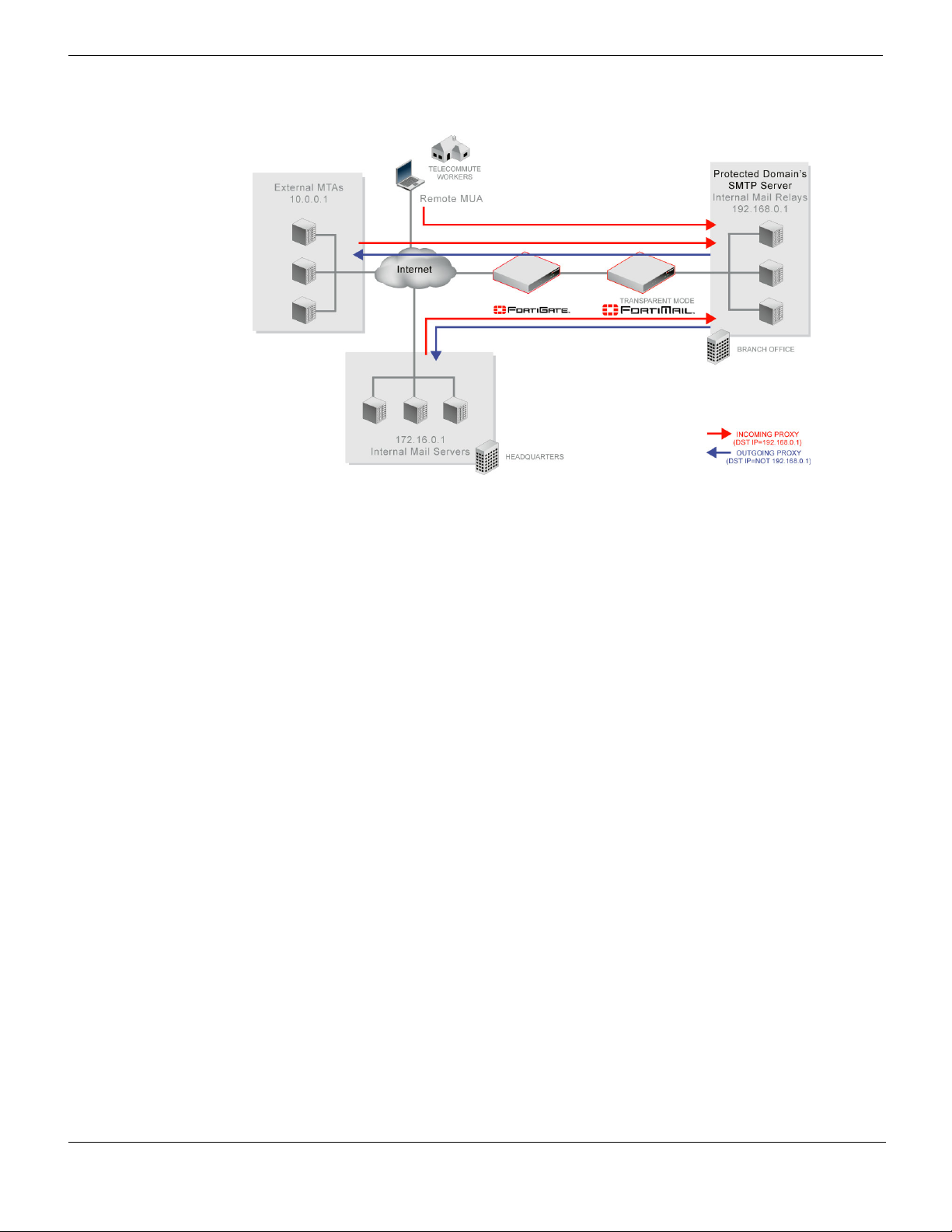
Figure 1: Incoming vs. outgoing SMTP connections
Directionality at the connection level may be different than directionality at the level of
email messages contained by the connection. It is possible that an incoming connection
could contain an outgoing email message, and vice versa.
For example, in Figure 1 on page 16, connections from the internal mail relays to the
internal mail servers are outgoing connections, but they contain incoming email
messages. Conversely, connections from remote MUAs to the internal mail relays are
incoming connections, but may contain outgoing email messages if the recipients’ email
addresses (RCPT TO:) are external.
Similarly to when determining the directionality of an SMTP connection, when determining
the directionality of an email message, FortiMail units examine the domain to which the
recipient belongs: if the domain to which the recipient email address belongs is a
protected domain, the email message is considered to be incoming; if the domain to which
the recipient email address belongs is not a protected domain, the email message is
considered to be outgoing.
The role of DNS in email delivery
SMTP can be configured to operate without DNS, using IP addresses instead of domain
names for SMTP clients, SMTP servers, and recipient email addresses. However, this
configuration is rare.
SMTP as it is typically used relies upon DNS to determine the mail gateway server (MX)
for a domain name, and to resolve domain names into IP addresses. As such, you usually
must configure email servers and FortiMail units to be able to query a DNS server.
In addition, you may also be required to configure the DNS server with an MX record, an A
record, and a reverse DNS record for protected domain names and for the domain name
of the FortiMail unit itself.
FortiMail™ Secure Messaging Platform Version 4.0 Patch 1 Install Guide
16 Revision 2
http://docs.fortinet.com/ • Feedback
Page 17

Key concepts The role of DNS in email delivery
MX record
Mail Exchanger (MX) records are configured on a DNS server. MX records for a domain
name indicate designated email servers or email gateways that deliver email to that
domain, and their order of preference. In their most simple form, MX records use the
following format:
example.com IN MX 10 mail.example.com
where:
• example.com is the name of the domain
• IN indicates the Internet protocol class
• MX indicates that the DNS resource record is of the MX type
• 10 indicates the order of preference (greater values indicate lower preference)
• mail.example.com is the host name of an email server or gateway
When an email client sends an email, the sender’s MTA queries a DNS server for the MX
record of the domain name in the recipient’s email address. To resolve the host name of
the MTA referenced by the MX record, it then queries for the A record of the destination
MTA. That A record provides the IP address of the email server or gateway. The sender’s
MTA then attempts to deliver the email to that IP address.
For example, if the recipient email address is user1@example.com, in order to deliver the
email, the sender’s MTA would query the MX and A records to determine the IP address of
the email gateway of example.com.
Often, the domain name and/or IP address of the email domain is different from that of its
email server or gateway. The fully qualified domain name (FQDN) of an email server or
gateway may be a subdomain or another domain name entirely, such as that of the MTA of
an Internet service provider (ISP). For example, the email gateways for the email domain
example.com could be mail1.example.com and mail2.example.com, or
mail.isp.example.net.
If your FortiMail unit will operate in transparent mode, and you will configure it be fully
transparent at both the IP layer and in the SMTP envelope and message headers by
enabling “Hide this box from the mail server” in the session profile, “Hide the transparent
box” in the protected domain, and “Use client-specified SMTP server to send email” for the
proxies, no MX record changes are required.
If your FortiMail unit will operate in gateway mode or server mode, or in transparent mode
while not configured to be fully transparent, you must configure the public DNS server for
your domain name with an MX record that refers to the FortiMail unit which will operate as
the email gateway, such as:
example.com IN MX 10 fortimail.example.com
Caution: If your FortiMail unit will operate in gateway mode or server mode, or in
transparent mode while not fully transparent, configure the MX record to refer to the
FortiMail unit, and remove other MX records. If you do not configure the MX record to refer
to the FortiMail unit, or if other MX records exist that do not refer to the FortiMail unit,
external MTAs may not be able to deliver email to or through the FortiMail unit, or may be
able to bypass the FortiMail unit. If you have configured secondary MX records for failover
reasons, consider configuring FortiMail high availability (HA) instead. For details, see
“FortiMail high availability modes” on page 19.
Note: For more information on gateway mode and server mode, see “FortiMail operation
modes” on page 19.
FortiMail™ Secure Messaging Platform Version 4.0 Patch 1 Install Guide
Revision 2 17
http://docs.fortinet.com/ • Feedback
Page 18

The role of DNS in email delivery Key concepts
Exceptions include if you are configuring a private DNS server for use with the Use MX
Record option (see “Use MX Record” on page 83). In that case, rather than referencing
the FortiMail unit as the mail gateway and being used by external SMTP servers to route
mail, the MX record references the protected SMTP server and is used by the FortiMail
unit to define the SMTP servers for the protected domain.
A record
A records are configured on a DNS server. A records indicate the IP address to which a
host name resolves. In their most simple form, A records use the following format:
mail IN A 192.168.1.10
where:
• mail is the name of the host
• IN indicates the Internet protocol class
• A indicates that the DNS resource record is of the IPv4 address type
• 192.168.1.10 indicates the IP address that hosts the domain name
When an email client sends an email, the sender’s MTA queries a DNS server for the MX
record of the domain name in the recipient’s email address. To resolve the host name of
the MTA referenced by the MX record, it then queries for the A record of the destination
MTA. That A record provides the IP address of the email server or gateway. The sender’s
MTA then attempts to deliver the email to that IP address.
You must configure the public DNS server for your host names with an A record to resolve
the host names referenced in MX records, and the host name of the FortiMail unit, if any.
For example, if an MX record is:
example.com IN MX 10 fortimail.example.com
the required A record in the example.com zone file might be:
fortimail IN A 192.168.1.15
Reverse DNS record
Because the SMTP protocol does not strictly require SMTP clients to use their own
domain name during the SMTP greeting, it is possible to spoof the origin domain. In an
attempt to bypass antispam measures against domain names known to be associated
with spam, spammers often exploit that aspect of SMTP by pretending to send email from
legitimate domains.
For example, the spammer spam.example.com might initiate an SMTP session with the
command:
EHLO nonspam.example.edu
To prevent this form of attack, many SMTP servers query reverse DNS records to verify
that the domain name provided in the SMTP greeting genuinely matches the IP address of
the connecting SMTP client.
You should configure the public DNS server for your protected domain names with a
reverse DNS record to resolve the IP addresses of your protected SMTP servers and/or
FortiMail unit into domain names.
For example, if the outgoing MTA for example.com is the FortiMail unit,
fortimail.example.com, and the public network IP address of the FortiMail unit is
10.10.10.1, a public DNS server’s reverse DNS zone file for the 10.10.10.0/24 subnet
might contain:
1 IN PTR fortimail.example.com.
FortiMail™ Secure Messaging Platform Version 4.0 Patch 1 Install Guide
18 Revision 2
http://docs.fortinet.com/ • Feedback
Page 19

Key concepts FortiMail web-based manager modes
where fortimail.example.com is the FQDN of the FortiMail unit.
Note: Reverse DNS records are required for FortiMail units operating in gateway mode or
server mode. However, they are also required for FortiMail units operating in transparent
mode, unless they have been configured to be completely transparent. For more
information on transparency, see the FortiMail Administration Guide.
FortiMail web-based manager modes
The web-based manager has two modes: basic mode and advanced mode.
• Basic mode: Provides easy navigation using a simplified set of menu options that
allow for many typical FortiMail unit configurations, and includes the Quick Start
Wizard.
• Advanced mode: Provides the full set of menu options which allows you to achieve
more complex configurations, but does not include the Quick Start Wizard.
Unless otherwise specified, this document describes setup of the FortiMail unit using the
basic mode of the web-based manager.
For more information on basic mode, advanced mode, the Quick Start Wizard, or
configuring your FortiMail unit using either mode of the web-based manager, see the
FortiMail Administration Guide.
FortiMail operation modes
FortiMail units can run in one of three operation modes: gateway mode, transparent mode,
and server mode.
• Gateway mode: The FortiMail unit acts as a mail transfer agent (MTA), or email
gateway, relaying email to and from the email servers that it protects. It does not locally
store email unless queued or quarantined.
• Transparent mode: The FortiMail unit transparently proxies or relays email traffic to
and from the email servers that it protects. It does not locally store email unless
queued or quarantined.
• Server mode: The FortiMail unit operates as a stand-alone email server and MTA. The
FortiMail unit locally stores email for delivery to its email users. Email users can access
their email using FortiMail webmail, POP3, or IMAP.
All operation modes can scan email traffic for viruses and spam, and can quarantine
suspicious email and attachments.
For more information on the differences between operation modes and configuring the
operation mode, see “Choosing the operation mode” on page 71.
FortiMail high availability modes
FortiMail units can be configured to operate in high availability (HA) clusters. FortiMail HA
has two modes: active-passive and config-only.
• Active-passive HA: Two FortiMail units operate as an HA cluster, synchronizing both
configuration and data, providing failover protection.
• Config-only HA: Up to 25 FortiMail units use an identical configuration, but do not
synchronize data, and therefore operate as independent FortiMail units.
Fortinet recommends HA to achieve uninterrupted service.
FortiMail™ Secure Messaging Platform Version 4.0 Patch 1 Install Guide
Revision 2 19
http://docs.fortinet.com/ • Feedback
Page 20

FortiMail high availability modes Key concepts
For more information on HA, see the FortiMail Administration Guide.
FortiMail™ Secure Messaging Platform Version 4.0 Patch 1 Install Guide
20 Revision 2
http://docs.fortinet.com/ • Feedback
Page 21

Hardware installation Cautions and warnings
Hardware installation
This chapter provides information on mounting and connecting a FortiMail unit (except for
the FortiMail-2000B unit and FortiMail-5001A board) to your network. For information
about installing the FortiMail-2000B unit, see “FortiMail-2000B hardware installation” on
page 33. For information about installing the FortiMail-5001A board, see the “FortiMail5001A hardware installation” on page 53.
This chapter includes the following topics:
• Cautions and warnings
• Environmental specifications
• Mounting the FortiMail unit
• Powering on the FortiMail unit
• Turning off the FortiMail unit
• Connecting to the web-based manager or CLI
Cautions and warnings
Review the following cautions before installing your FortiMail unit.
Grounding
• Ensure the FortiMail unit is connected and properly grounded to a lightning and surge
protector. WAN or LAN connections that enter the premises from outside the building
should be connected to an Ethernet CAT5 (10/100 Mb/s) surge protector.
• Shielded Twisted Pair (STP) Ethernet cables should be used whenever possible rather
than Unshielded Twisted Pair (UTP).
• Do not connect or disconnect cables during lightning activity to avoid damage to the
FortiMail unit or personal injury.
Rack mount instructions
• Elevated Operating Ambient: If installed in a closed or multi-unit rack assembly, the
operating ambient temperature of the rack environment may be greater than room
ambient temperature. Therefore, consideration should be given to installing the
equipment in an environment compatible with the maximum ambient temperature
(Tma) specified by the manufacturer.
• Reduced Air Flow: Installation of the equipment in a rack should be such that the
amount of air flow required for safe operation of the equipment is not compromised.
• Mechanical Loading: Mounting of the equipment in the rack should be such that a
hazardous condition is not achieved due to uneven mechanical loading.
• Circuit Overloading: Consideration should be given to the connection of the
equipment to the supply circuit and the effect that overloading of the circuits might have
on overcurrent protection and supply wiring. Appropriate consideration of equipment
nameplate ratings should be used when addressing this concern.
• Reliable Earthing: Reliable earthing of rack-mounted equipment should be
maintained.
Particular attention should be given to supply connections other than direct connections to
the branch circuit (e.g. use of power strips).
FortiMail™ Secure Messaging Platform Version 4.0 Patch 1 Install Guide
Revision 2 21
http://docs.fortinet.com/ • Feedback
Page 22

Environmental specifications Hardware installation
If required to fit into a rack unit, remove the rubber feet from the bottom of the FortiMail
unit.
Environmental specifications
• Operating temperature: 32 to 104°F (0 to 40°C)
If you install the FortiMail unit in a closed or multi-unit rack assembly, the operating
ambient temperature of the rack environment may be greater than room ambient
temperature. Therefore, make sure to install the equipment in an environment
compatible with the manufacturer's maximum rated ambient temperature.
• Storage temperature: -13 to 158°F (-25 to 70°C)
• Humidity: 5 to 90% non-condensing
• Air flow: For rack installation, make sure that the amount of air flow required for safe
operation of the equipment is not compromised.
For free-standing installation, make sure that the FortiMail unit has sufficient clearance
on each side to allow for adequate air flow and cooling.
Mounting the FortiMail unit
FortiMail-100 and FortiMail-100C
Adhere the rubber feet included in the package to the underside of the FortiMail unit, near
the corners of the unit if not already attached.
Place the FortiMail unit on any flat, stable surface. Ensure the FortiMail unit has sufficient
clearance on each side to ensure adequate airflow for cooling.
If you remove the rubber feet, you can alternatively mount the FortiMail unit in a 2U-tall
space in any standard 19-inch rack unit.
FortiMail-400
The FortiMail unit can be placed on any flat surface, or mounted in a standard 19-inch rack
unit.
When placing the FortiMail unit on any flat, stable surface, ensure the FortiMail unit has
sufficient clearance on each side to ensure adequate airflow for cooling.
For rack mounting, use the mounting brackets and screws included with the FortiMail unit.
Caution: To avoid personal injury, you may require two or more people to mount the
FortiMail unit in the rack.
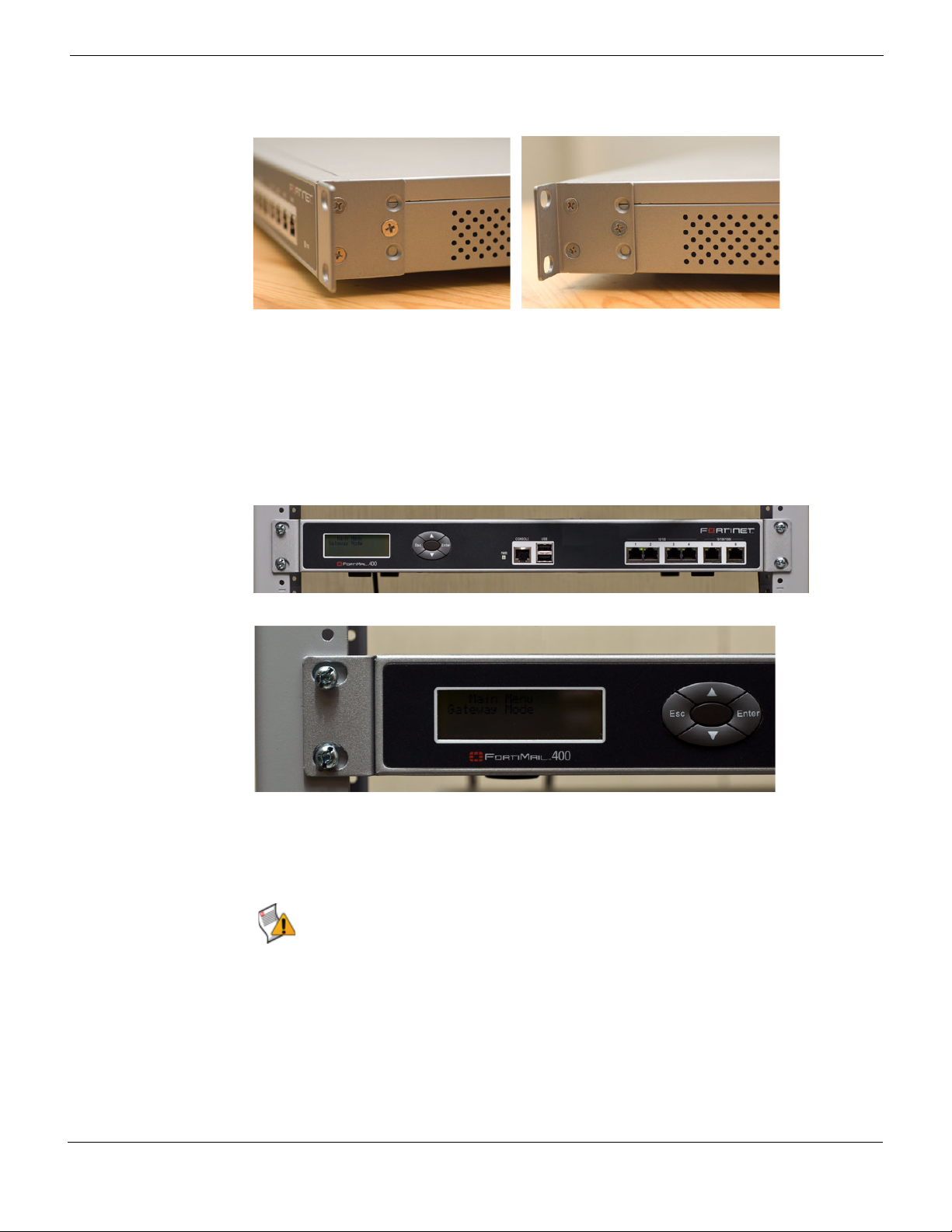
To install the FortiMail unit into a rack
1 Attach the mounting brackets to the side to the unit so that the brackets are on the front
portion of the FortiMail unit.
The following photos illustrate how the brackets should be mounted. Note that the
screw configuration may vary.
FortiMail™ Secure Messaging Platform Version 4.0 Patch 1 Install Guide
22 Revision 2
http://docs.fortinet.com/ • Feedback
Page 23
Hardware installation Mounting the FortiMail unit
Figure 2: Installed mounting brackets
2 Position the FortiMail unit in the rack to allow for sufficient air flow.
3 Line up the mounting bracket holes to the holes on the rack, ensuring the FortiMail unit
is level.
4 Finger tighten the screws to attach the FortiMail unit to the rack.
5 Once you verify the spacing of the FortiMail unit and that it is level, tighten the screws
with a screwdriver.
Figure 3: Mounting in a rack
FortiMail-2000A and FortiMail-4000A
To mount the FortiMail unit on a 19-inch rack or cabinet, use the slide rails included with
the product.
Caution: To avoid personal injury or damage to the FortiMail unit, it is highly recommended
a minimum of two people perform this procedure.
Mounting requires three steps:
• disassembling the slide rail from the slide housing
• attaching the slide rail to the sides of the FortiMail unit
• mounting the FortiMail unit to the rack or cabinet
FortiMail™ Secure Messaging Platform Version 4.0 Patch 1 Install Guide
Revision 2 23
http://docs.fortinet.com/ • Feedback
Page 24
Mounting the FortiMail unit Hardware installation
Rail housing
Sliding Rail
Rail Lock
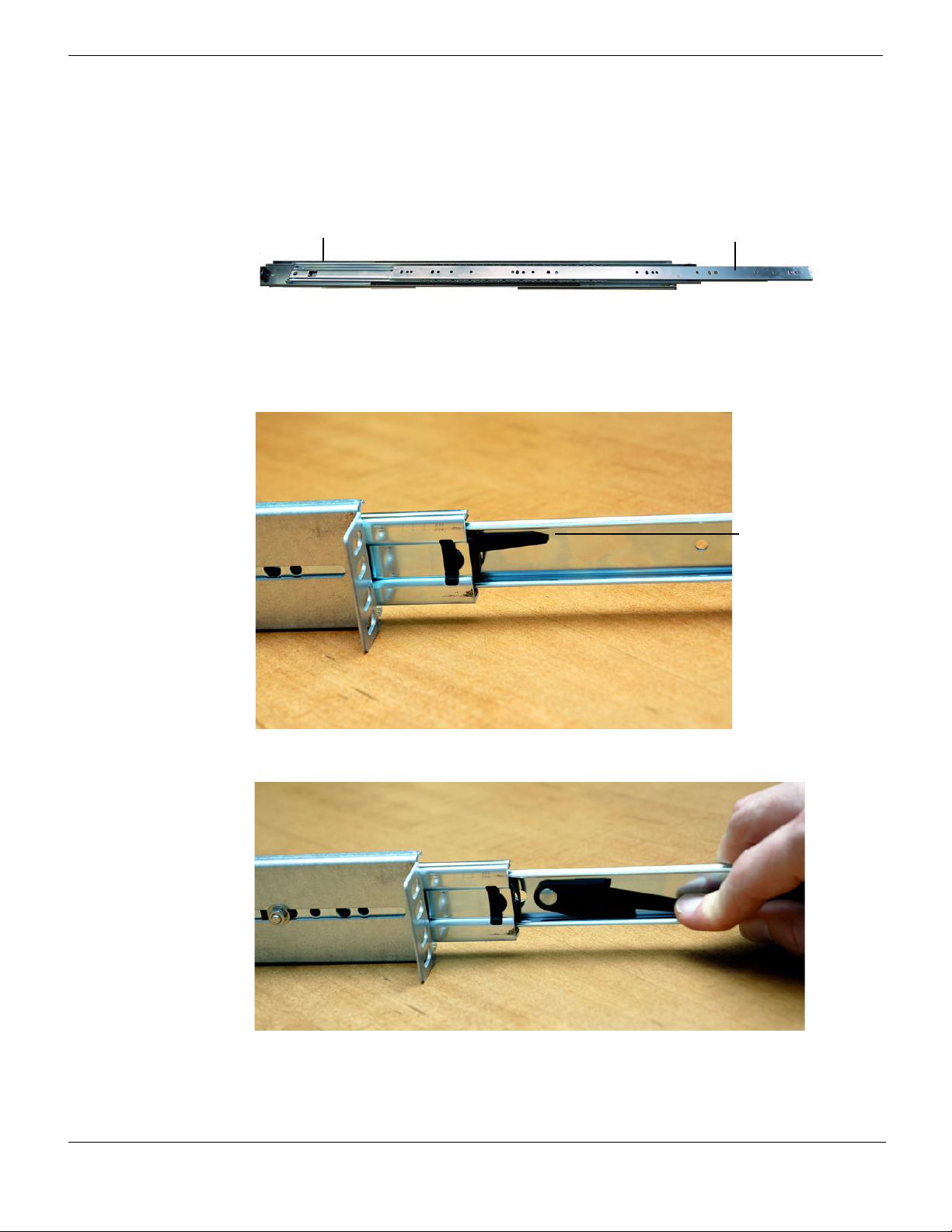
Disassembling the slide rail
The slide rail assembly has two moving rails within the housing. You need to remove the
innermost rail. This rail will attach to the sides of the FortiMail unit.
Figure 4: FortiMail side rail
To remove the side rail
1 Open the slide rails package and remove the rails.
2 Extend the slide rail and locate the slide rail lock.
3 Push down on the lock while pulling the rail completely out of the slide rail assembly.
4 Repeat these steps for the other slide rail assembly.
You will attach this part to the side of the FortiMail unit.
24 Revision 2
FortiMail™ Secure Messaging Platform Version 4.0 Patch 1 Install Guide
http://docs.fortinet.com/ • Feedback
Page 25
Hardware installation Mounting the FortiMail unit
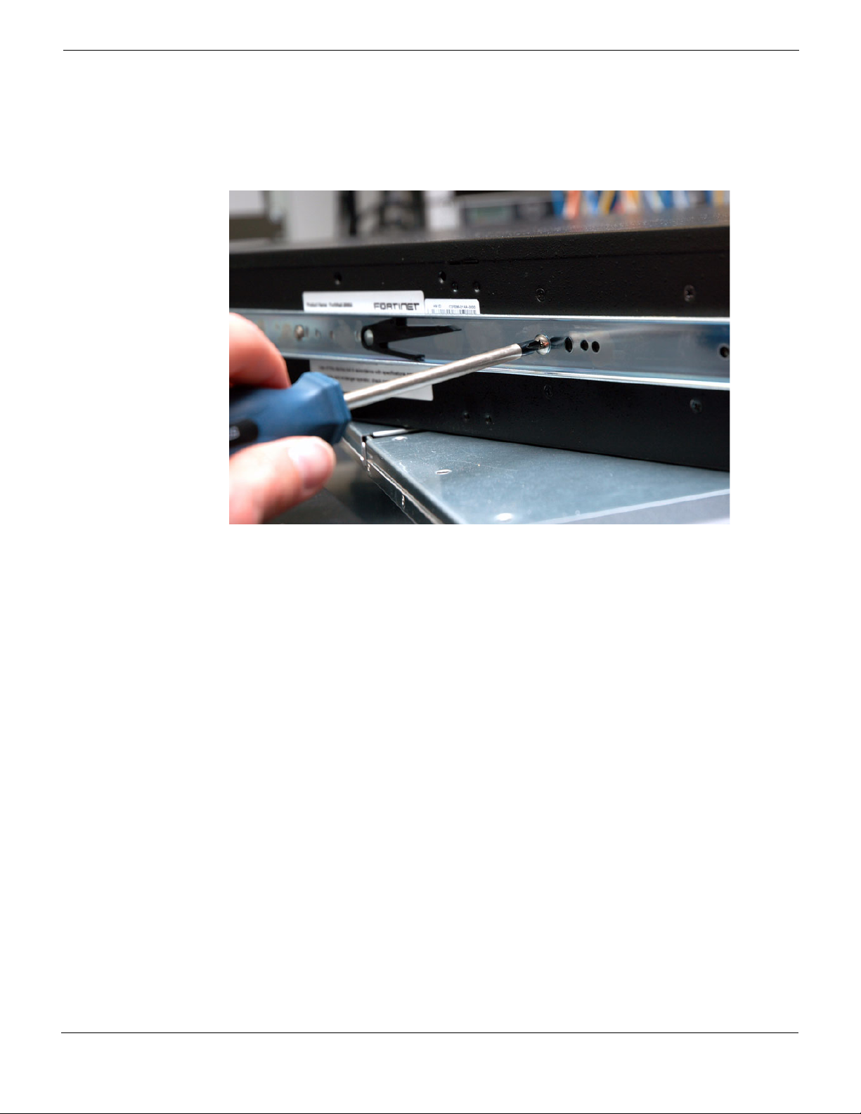
Attaching the slide rail to the FortiMail unit
Attach the disconnected slide rails from the previous step to the sides of the FortiMail unit.
Use the screws provided with the slide rail package, being sure to securely fasten the rail
to the FortiMail chassis.
Mounting the FortiMail unit
Mounting the FortiMail-2000A or FortiMail-4000A is a two step process. First, you must
attached the slide rail housing to the rack or cabinet, then insert the FortiMail unit.
To mount the FortiMail unit
1 Mount the slide rail housing to the rack or cabinet frame. Adjust the outside L-shaped
brackets for a proper fit. Ensure that both housings are on the same level to ensure the
FortiMail unit can easily glide into place and is level.
2 Use the screws and additional L-brackets if required to securely fasten the housing.
3 Position the FortiMail unit so that the back of the unit is facing the rack, and the slide
rails affixed in the previous step line up with the slide rail housing.
4 Gently push the FortiMail unit into the rack or cabinet. You will hear a click when the
slide rail lock has been engaged.
5 Push the FortiMail unit until it is fully inserted into the rack.
FortiMail-2000B
The FortiMail-2000B rack mounting and hard drive installation is described in the
“FortiMail-2000B hardware installation” on page 33.
FortiMail-5001A
Before using the FortiMail-5001A board, it must be inserted into an Advanced
Telecommunications Computing Architecture (ACTA) chassis such as the FortiGate-5140,
FortiGate-5050, or FortiGate-5020 chassis.
FortiMail™ Secure Messaging Platform Version 4.0 Patch 1 Install Guide
Revision 2 25
http://docs.fortinet.com/ • Feedback
Page 26

Powering on the FortiMail unit Hardware installation
For information about installing the FortiMail-5001A board, see the “FortiMail-5001A
hardware installation” on page 53.
Powering on the FortiMail unit
FortiMail-100 and FortiMail-100C
The FortiMail-100 does not have a power switch.
To power on the FortiMail unit
1 Connect the AC adapter to the power connection at the back of the FortiMail unit.
2 Connect the AC adapter to the power cable.
3 Connect the power cable to a power outlet.
The FortiMail unit starts and the Power and Status LEDs light up. The Status LEDs
flash while the FortiMail unit starts up, and remain lit when the system is running.
FortiMail-400
Use the following steps to connect the power supply to the FortiMail unit.
To power on the FortiMail unit
1 Ensure the power switch, located at the back of the FortiMail unit is in the off position,
indicated by the “O”.
2 Connect the power cord at the back of the FortiMail unit.
3 Connect the power cable to a power outlet.
4 Set the power switch on the back left of the FortiMail unit to the on position indicated by
the “I”.
After a few seconds, SYSTEM STARTING appears on the LCD. The main menu setting
appears on the LCD when the system is running.
FortiMail-2000A and FortiMail-4000A
The FortiMail unit does not have an on/off switch.
To power on the FortiMail unit
1 Connect the two power cables to the power connections on the back of the
FortiMail unit.
2 Connect the two power cables to power outlets.
Each power cable should be connected to a different power source. If one power
source fails, the other may still be operative.
After a few seconds, SYSTEM STARTING appears on the LCD. The main menu setting
appears on the LCD when the system is running.
The FortiMail unit starts and the Power and Status LEDs light up. The Status LEDs
flash while the FortiMail unit starts up, and remain lit when the system is running.
Note: If only one power supply is connected, an audible alarm sounds to indicate a failed
power supply. Press the red alarm cancel button on the rear panel next to the power supply
to stop the alarm.
FortiMail™ Secure Messaging Platform Version 4.0 Patch 1 Install Guide
26 Revision 2
http://docs.fortinet.com/ • Feedback
Page 27

Hardware installation Turning off the FortiMail unit
FortiMail-2000B
Use the following steps to connect the power supply to the FortiMail unit.
To power on the FortiMail unit
1 Connect the two power cables to the power connections on the back of the
FortiMail unit.
2 Connect the two power cables to power outlets.
Each power cable should be connected to a different power source. If one power
source fails, the other may still be operative.
3 Press the power switch on the front to turn on the unit.
FortiMail-5001A
To power on the FortiMail-5001A board, you must turn on the chassis power. For details,
see the FortiGate 5000 series chassis guides at http://docs.fortinet.com.
Connecting to the network
Until the FortiMail unit is configured with an IP address and other settings in the Quick
Start Wizard required to connect to your network, you may prefer to connect the FortiMail
unit directly to your management computer, or through a switch, in a peer network that is
isolated from your overall network. However, isolation is not required.
Note: If you will upgrade the FortiMail firmware and configure the FortiMail unit while it is
isolated from your overall network, download the FortiMail firmware to your management
computer before disconnecting it from your overall network. For details, see “Updating the
firmware” on page 63.
Using the supplied Ethernet cable, connect one end of the cable to port1 on the FortiMail
unit; connect the other end of the cable to the router, switch, or directly to your
management computer.
Turning off the FortiMail unit
Always shut down the FortiMail unit properly before turning off the power switch to avoid
potential hardware problems. This enables the hard drives to spin down and park correctly
and avoid losing data.
To power off the FortiMail unit
1 From the web-based manager (see “Connecting to the web-based manager” on
page 28), go to Management > Status > Status in the basic mode of the web-based
manager, or System > Status > Status in the advanced mode of the web-based
manager.
2 In the System Command widget, select Shutdown.
3 Turn off and/or disconnect the power cables from the power supply.
Powering off the FortiMail-5001A board
To avoid potential hardware problems or data loss, always shut down the board before
powering down the chassis.
FortiMail™ Secure Messaging Platform Version 4.0 Patch 1 Install Guide
Revision 2 27
http://docs.fortinet.com/ • Feedback
Page 28

Connecting to the web-based manager or CLI Hardware installation
Note: Executing a shutdown command will shut down the board’s operating system. The
board itself will still receive power from the chassis and indicator lights on the board may
remain lit after a successful shut down operation.
Powering off the FortiMail board using the web-based manager
1 To shut down the FortiMail board, go to System > Status in the advanced
management mode or Management > Status in the basic management mode.
2 Select Shutdown under System Command.
3 Confirm the operation by selecting OK.
4 The FortiMail board is now shut down. Power to the chassis can be safely turned off.
Powering off the FortiMail board using the CLI commands
1 Connect to the FortiMail board and enter the shutdown command.
execute shutdown
2 Confirm the operation by pressing y.
You can now safely turn off power to the chassis.
Connecting to the web-based manager or CLI
To configure, maintain, and administer the FortiMail unit, you need to connect to it. There
are three methods for these tasks:
• using the web-based manager, a graphical user interface (GUI), from within a current
web browser
• using the command line interface (CLI), a command line interface similar to DOS or
UNIX commands, from a Secure Shell (SSH) or Telnet terminal
• using the front panel’s LCD display and control buttons on some models that are
equipped with LCD displays and control buttons
If you are connecting for the first time, or if you have just reset the configuration to its
default state, or have just restored the firmware, access to the CLI and/or web-based
manager is not yet configured, and you must access it using the default settings.
In that case, you can use the following procedures to connect.
After you have connected, you can use the web-based manager or CLI to configure basic
network settings and access to the CLI and/or web-based manager through your network.
Connecting to the web-based manager
To connect to the web-based manager using its default settings, you must have:
• a computer with an Ethernet port
• a web browser such as Microsoft Internet Explorer version 6.0 or greater, or a recent
version of Mozilla Firefox, with Adobe Flash Player 10 or greater plug-in
• a crossover Ethernet cable
FortiMail™ Secure Messaging Platform Version 4.0 Patch 1 Install Guide
28 Revision 2
http://docs.fortinet.com/ • Feedback
Page 29

Hardware installation Connecting to the web-based manager or CLI
Table 2: Default settings for connecting to the web-based manager
Network Interface port1
URL https://192.168.1.99/admin
Administrator Account admin
Password (none)
To connect to the web-based manager
1 On your management computer, configure the Ethernet port with the static IP address
192.168.1.2 with a netmask of 255.255.255.0.
1 Using the Ethernet cable, connect your computer’s Ethernet port to the FortiMail unit’s
port1.
2 Start your web browser and enter the URL https://192.168.1.99/admin. (Remember to
include the “s” in https://.)
To support HTTPS authentication, the FortiMail unit ships with a self-signed security
certificate, which it presents to clients whenever they initiate an HTTPS connection to
the FortiMail unit. When you connect, depending on your web browser and prior
access of the FortiMail unit, your browser might display two security warnings related
to this certificate:
• The certificate is not automatically trusted because it is self-signed, rather than
being signed by a valid certificate authority (CA). Self-signed certificates cannot be
verified with a proper CA, and therefore might be fraudulent. You must manually
indicate whether or not to trust the certificate.
• The certificate might belong to another web site. The common name (CN) field in
the certificate, which usually contains the host name of the web site, does not
exactly match the URL you requested. This could indicate server identity theft, but
could also simply indicate that the certificate contains a domain name while you
have entered an IP address. You must manually indicate whether this mismatch is
normal or not.
Both warnings are normal for the default certificate.
3 Verify and accept the certificate, either permanently (the web browser will not display
the self-signing warning again) or temporarily. You will not be able to log in until you
have accepted the certificate.
For details on accepting the certificate, see the documentation for your web browser.
4 In the Name field, type admin, then select Login. (In its default state, there is no
password for this account.)
Login credentials entered are encrypted before they are sent to the FortiMail unit. If
your login is successful, the web-based manager is displayed. To continue, see
“Updating the firmware” on page 63.
Connecting to the CLI
Using its default settings, you can access the CLI from your management computer using
either of these two ways:
• a local serial console connection
• an SSH connection, either local or through the network
To connect to the CLI using a local serial console connection, you must have:
• a computer with a serial communications (COM) port
FortiMail™ Secure Messaging Platform Version 4.0 Patch 1 Install Guide
Revision 2 29
http://docs.fortinet.com/ • Feedback
Page 30

Connecting to the web-based manager or CLI Hardware installation
• the RJ-45-to-DB-9 serial or null modem cable included in your FortiMail package
• terminal emulation software, such as HyperTerminal for Microsoft Windows
To connect to the CLI using an SSH connection, you must have:
• a computer with an Ethernet port
• a crossover Ethernet cable
• an SSH client, such as PuTTY
Table 3: Default settings for connecting to the CLI by SSH
Network Interface port1
IP Address 192.168.1.99
SSH Port Number 22
Administrator Account admin
Password (none)
To connect to the CLI using a local serial console connection
Note: The following procedure uses Microsoft HyperTerminal. Steps may vary with other
terminal emulators.
1 Using the RJ-45-to-DB-9 or null modem cable, connect your computer’s serial
communications (COM) port to the FortiMail unit’s console port.
2 Verify that the FortiMail unit is powered on.
3 On your management computer, start HyperTerminal.
4 On Connection Description, enter a Name for the connection, and select OK.
5 On Connect To, from Connect using, select the communications (COM) port where you
connected the FortiMail unit.
6 Select OK.
7 Select the following Port settings and select OK.
Bits per second 9600
Data bits 8
Parity None
Stop bits 1
Flow control None
8 Press Enter.
The terminal emulator connects to the CLI, and the CLI displays a login prompt.
9 Type admin and press Enter twice. (In its default state, there is no password for this
account.)
The CLI displays the following text:
Welcome!
Type ? for a list of commands.
You can now enter commands. To continue, see “Updating the firmware” on page 63.
For information about how to use the CLI, including how to connect to the CLI using
SSH or Telnet, see the FortiMail CLI Reference.
FortiMail™ Secure Messaging Platform Version 4.0 Patch 1 Install Guide
30 Revision 2
http://docs.fortinet.com/ • Feedback
Page 31

Hardware installation Connecting to the web-based manager or CLI
To connect to the CLI using an SSH connection
Note: The following procedure uses PuTTY. Steps may vary with other SSH clients.
1 On your management computer, configure the Ethernet port with the static IP address
192.168.1.2 with a netmask of 255.255.255.0.
2 Using the Ethernet cable, connect your computer’s Ethernet port to the FortiMail unit’s
port1.
3 Verify that the FortiMail unit is powered on.
4 On your management computer, start your SSH client.
5 In Host Name (or IP Address), type 192.168.1.99.
6 In Port, type 22.
7 From Connection type, select SSH.
8 Select Open.
The SSH client connects to the FortiMail unit.
The SSH client may display a warning if this is the first time you are connecting to the
FortiMail unit and its SSH key is not yet recognized by your SSH client, or if you have
previously connected to the FortiMail unit but it used a different IP address or SSH key.
If your management computer is directly connected to the FortiMail unit with no
network hosts between them, this is normal.
9 Click Yes to verify the fingerprint and accept the FortiMail unit’s SSH key. You will not
be able to log in until you have accepted the key.
The CLI displays a login prompt.
10 Type admin and press Enter. (In its default state, there is no password for this
account.)
The CLI displays the following text:
Type ? for a list of commands.
You can now enter commands. To continue, see “Updating the firmware” on page 63.
For information about how to use the CLI, including how to connect to the CLI using
SSH or Telnet, see the FortiMail CLI Reference.
Using the front panel’s control buttons and LCD display
On FortiMail-400 and FortiMail-2000 models, you can use the front panel’s control buttons
and LCD display to configure:
• IP addresses and netmasks for each of the network interfaces
• the default gateway
• the operating mode
You can also use the front panel to reset the FortiMail unit to the default settings for its
firmware version.
FortiMail™ Secure Messaging Platform Version 4.0 Patch 1 Install Guide
Revision 2 31
http://docs.fortinet.com/ • Feedback
Page 32

Connecting to the web-based manager or CLI Hardware installation
Table 4: Control buttons on the front panel
Button Description
Enter Move into the currently selected menu area, or confirm your selected
Esc Exit the current menu area.
Up Select the previous option, or increase the number for an IP address,
Down Select the next option, or decrease the number for an IP address,
option.
default gateway address, or netmask.
default gateway address, or netmask.
After using the front panel to configure these basic settings, you must still connect to the
web-based manager to complete additional setup. To continue, see “Connecting to the
web-based manager” on page 28.
FortiMail™ Secure Messaging Platform Version 4.0 Patch 1 Install Guide
32 Revision 2
http://docs.fortinet.com/ • Feedback
Page 33

FortiMail-2000B hardware installation Mounting the FortiMail unit
FortiMail-2000B hardware installation
This chapter describes:
• Mounting the FortiMail unit
• Installing the cable management arm
• Installing the hard drives
• Installing the bezel
• Connecting the keyboard, mouse, and monitor
• Connecting the power cables
• Securing the power cord
Mounting the FortiMail unit
The FortiMail-2000B unit comes with a sliding rail kit. Use the instructions below to install
the rails.
Caution: Only trained service technicians are authorized to remove the system cover and
access any of the components inside the system. Before you begin, review the safety
instructions that came with the system.
Note: The illustrations in this document are not intended to represent a specific server.
To install the sliding rail kit
1 Locate the components for installing the rail kit assembly:
• Two sliding rail assemblies (1)
• Two Velcro straps (2)
FortiMail™ Secure Messaging Platform Version 4.0 Patch 1 Install Guide
Revision 2 33
http://docs.fortinet.com/ • Feedback
Page 34

Mounting the FortiMail unit FortiMail-2000B hardware installation
1
2
Figure 1: Rail kit contents
2 In square-hole racks, do the following:
• Position the left and right rail end pieces of the rail module labeled FRONT facing
inward and orient each end piece to seat in the square holes on the front side of the
vertical rack flanges (3).
FortiMail™ Secure Messaging Platform Version 4.0 Patch 1 Install Guide
34 Revision 2
http://docs.fortinet.com/ • Feedback
Page 35

FortiMail-2000B hardware installation Mounting the FortiMail unit
3
6
5
4
Figure 2: Installing and removing the rails (square-hole racks)
• Align each end piece to seat the pegs in the bottom hole of the first U and the top
hole of the second U (4).
• Engage the back end of the rail until it fully seats on the vertical rack flange and the
second “tooth” on the latch locks in place. Repeat these steps to position and seat
the front end piece on the vertical flange (5).
• To remove the rails, pull on the latch release button on the end piece midpoint and
unseat each rail (6).
3 In round-hole racks, do the following:
• Position the left and right rail end pieces of the rail module labeled FRONT facing
inward and orient each end piece to seat in the round holes on the front side of the
vertical rack flanges (7).
FortiMail™ Secure Messaging Platform Version 4.0 Patch 1 Install Guide
Revision 2 35
http://docs.fortinet.com/ • Feedback
Page 36

Mounting the FortiMail unit FortiMail-2000B hardware installation
7
8
9
10
Figure 3: Installing and removing the rails (round-hole racks)
• Align each end piece to seat the pegs in the bottom hole of the first U and the top
hole of the second U (8).
• Engage the back end of the rail until it fully seats on the vertical rack flange and the
first “tooth” on the latch locks in place. Repeat these steps to position and seat the
front end piece on the vertical flange (9).
• To remove the rails, pull on the latch release button on the end piece midpoint and
unseat each rail (10).
4 To install the system into the rack, do the following:
• Pull the inner slide rails out of the rack until they lock into place (11).
FortiMail™ Secure Messaging Platform Version 4.0 Patch 1 Install Guide
36 Revision 2
http://docs.fortinet.com/ • Feedback
Page 37

FortiMail-2000B hardware installation Mounting the FortiMail unit
11
12
13
14
Figure 4: Installing the system on the rack
• Locate the three shoulder screws on one side of the system and lower them into the
J-slots on the slide assembly (12).
• Seat the three screws on the other side, lowering the system until all shoulder
screws engage in the J-slots (13).
• Push the system inward until the front release latch clicks into place. Press the
slide-release lock buttons on both rails and slide the system into the rack (14).
5 To engage and release the slam latch, do the following:
• Facing the front, locate the slam latch on either side of the system (15).
FortiMail™ Secure Messaging Platform Version 4.0 Patch 1 Install Guide
Revision 2 37
http://docs.fortinet.com/ • Feedback
Page 38

Mounting the FortiMail unit FortiMail-2000B hardware installation
1
2
3
Figure 5: Engaging and releasing the slam latch
• The latches engage automatically as the system is pushed into the rack and are
released by pulling up on the latches (16).
• To secure the system for shipment in the rack or for other unstable environments,
locate the hard-mount screw under each latch and tighten each screw with a #2
Phillips screwdriver (17).
6 To route the cables, do the following:
• Locate the inner and outer CMA brackets on the interior sides of both rack flanges
(18).
FortiMail™ Secure Messaging Platform Version 4.0 Patch 1 Install Guide
38 Revision 2
http://docs.fortinet.com/ • Feedback
Page 39

FortiMail-2000B hardware installation Mounting the FortiMail unit
18
20
19
Figure 6: Routing the cables
• Bundle the cables gently, pulling them clear of the system connectors to the left and
right sides (19).
• Thread the Velcro straps through the tooled slots on the outer or inner CMA
brackets on each side of the system to secure the cable bundles (20).
Removing the system from the rack
To remove the system from the rack
1 Locate the lock levers on the front ends of both inner rails (1).
FortiMail™ Secure Messaging Platform Version 4.0 Patch 1 Install Guide
Revision 2 39
http://docs.fortinet.com/ • Feedback
Page 40

Installing the cable management arm FortiMail-2000B hardware installation
1
3
2
Figure 7: Removing the system from the rack
2 Pull up on each lever into the release position to unlock (2).
3 Grasp the sides of the system firmly and pull forward and up to unseat the system from
the J-slots. Lift the system up and away from the rack and place on a level surface (3).
Installing the cable management arm
The FortiMail-2000B unit comes with a cable management arm. Use the instructions
below to install the arm.
Caution: Only trained service technicians are authorized to remove the system cover and
access any of the components inside the system. Before you begin, review the safety
instructions that came with the system.
Note: The illustrations in this document are not intended to represent a specific server.
To install the cable management arm
1 Locate the components for installing the Cable Management Arm (CMA) assembly:
• Cable Management Arm tray (1)
• Cable Management Arm (2)
• Nylon cable tie wraps (3)
40 Revision 2
FortiMail™ Secure Messaging Platform Version 4.0 Patch 1 Install Guide
http://docs.fortinet.com/ • Feedback
Page 41

FortiMail-2000B hardware installation Installing the cable management arm
1
2
3
Figure 8: Cable Management Arm kit contents
Note: To secure the CMA for shipment in the rack, loop the tie wraps around both baskets
and tray and cinch them firmly. For larger CMAs, the tie wraps can be threaded through the
inner and outer baskets and around the tray to secure them. Securing the CMA in this
manner will also secure your system in unstable environments.
2 To install or remove the Cable Management Arm Tray, do the following:
Note: The CMA tray provides support and acts as a retainer for the CMA.
• Align and engage each side of the tray with the receiver brackets on the inner
edges of the rails and push forward until the tray clicks into place (4).
FortiMail™ Secure Messaging Platform Version 4.0 Patch 1 Install Guide
Revision 2 41
http://docs.fortinet.com/ • Feedback
Page 42

Installing the cable management arm FortiMail-2000B hardware installation
5
4
Figure 9: Installing and removing the cable management arm tray
• To remove the tray, squeeze the latch-release buttons on both sides toward the
center and pull the tray out of the receiver brackets (5).
3 To install and remove the CMA, do the following:
Note: You can attach the CMA to either the right or left mounting rail, depending on how
you intend to route cables from the system. Mounting the CMA on the side opposite of the
power supplies is recommended; otherwise, the CMA must be disconnected in order to
remove the outer power supply. You must remove the tray before removing the power
supplies.
• At the back of the system, fit the latch on the front end of the CMA on the innermost
bracket of the slide assembly until the latch engages (6).
FortiMail™ Secure Messaging Platform Version 4.0 Patch 1 Install Guide
42 Revision 2
http://docs.fortinet.com/ • Feedback
Page 43

FortiMail-2000B hardware installation Installing the cable management arm
6
7
8
Figure 10: Installing and removing the cable management arm
• Fit the other latch on the end of the outermost bracket until the latch engages (7).
• To remove the CMA, disengage both latches by pressing the CMA release buttons
at the top of the inner and outer latch housings (8).
4 To move the CMA away from the CMA tray, do the following:
• The CMA can be pulled away from the system and extended away from the tray for
access and service (9).
FortiMail™ Secure Messaging Platform Version 4.0 Patch 1 Install Guide
Revision 2 43
http://docs.fortinet.com/ • Feedback
Page 44

Installing the cable management arm FortiMail-2000B hardware installation
9
10
Figure 11: Moving the CMA away from the CMA tray
• At the hinged end, lift the CMA up and off of the tray to unseat it from the tray catch.
Once it is unseated from the tray, swing the CMA away from the system (10).
Note: You can also extend the CMA into the service position once it is cabled to access the
back of the system.
5 To cable the system using the CMA, do the following:
Caution: To avoid potential damage from protruding cables, secure any slack in the status
indicator cable before routing this cable through the CMA.
• Using the tie wraps provided, bundle the cables together as they enter and exit the
baskets so they do not interfere with adjacent systems (11).
FortiMail™ Secure Messaging Platform Version 4.0 Patch 1 Install Guide
44 Revision 2
http://docs.fortinet.com/ • Feedback
Page 45

FortiMail-2000B hardware installation Installing the hard drives
11
12
13
14
15
16
Figure 12: Cabling the system using the CMA
• With the CMA in the service position, route the cable bundle through the inner and
outer baskets (12).
• Use the preinstalled Velcro straps on either end of the baskets to secure the cables
(13).
• Adjust the cable slack as needed at the hinge position (14).
• Swing the CMA back into place on the tray (15).
• Install the status indicator cable at the back of the system and secure the cable by
routing it through the CMA. Attach the other end of this cable to the corner of the
outer CMA basket. (16).
Installing the hard drives
The FortiMail-2000B unit has six 3.5-inch drive bays. All chassis support hot-swappable
SAS and SATA hard drives.
All drives are installed at the front of the system and connect to the system board through
the SAS backplane. Hard drives are supplied in special hot-swappable hard-drive carriers
that fit in the hard-drive bays.
Caution: Do not turn off or reboot your system while the drive is being formatted. Doing so
can cause a drive failure
Note: Use only drives that have been tested and approved for use with the SAS backplane
board.
When you format a hard drive, allow enough time for the formatting to be completed. Be
aware that high-capacity hard drives can take a number of hours to format.
FortiMail™ Secure Messaging Platform Version 4.0 Patch 1 Install Guide
Revision 2 45
http://docs.fortinet.com/ • Feedback
Page 46

Installing the hard drives FortiMail-2000B hardware installation
3
1
2
3
Mixed SAS/SATA hard-drive configurations
Mixed hard-drive configurations of SAS and SATA drives are allowed. In this configuration,
two SAS drives must be installed in hard-drive slots 0 and 1 only. The remaining slots can
have SATA drives installed.
Mixed 2.5-inch and 3.5-inch configurations of SAS and SATA drives are also supported in
the 3.5-inch–bay chassis only. In this configuration, two 10,000-RPM 2.5-inch SAS drives
installed in 3.5-inch adapters must be used in hard-drive slots 0 and 1 only. The remaining
hard drives must be 3.5 inches in size and must be either all SAS or all SATA drives.
Removing a hard-drive blank
Caution: To maintain proper system cooling, all empty hard-drive bays must have drive
blanks installed
1 Remove the front bezel. See “Installing the Bezel” on page 18.
2 Grasp the front of the hard-drive blank, press the release lever on the right side, and
slide the blank out until it is free of the drive bay. See Figure 13.
Figure 13: Removing and Installing a Hard Drive Blank
1 3.5-in hard drive blank 2 2.5-in hard drive blank
3release latch
Installing a hard-drive blank
Align the hard-drive blank with the drive bay and insert the blank into the drive bay until the
release lever clicks into place.
Removing a hot-swap hard drive
Caution: Ensure that your operating system supports hot-swap drive removal and
installation. See the documentation provided with your operating system for more
information.
1 If present, remove the front bezel. See “Installing the Bezel” on page 18.
FortiMail™ Secure Messaging Platform Version 4.0 Patch 1 Install Guide
46 Revision 2
http://docs.fortinet.com/ • Feedback
Page 47

FortiMail-2000B hardware installation Installing the hard drives
2
1
2 From the RAID management software, prepare the drive for removal. Wait until the
hard-drive indicators on the drive carrier signal that the drive can be removed safely.
See your SAS RAID controller documentation for information about hot-swap drive
removal.
If the drive has been online, the green activity/fault indicator will flash as the drive is
powered down. When the drive indicators are off, the drive is ready for removal.
3 Press the button on the front of the drive carrier and open the drive carrier release
handle to release the drive. See Figure 14.
4 Slide the hard drive out until it is free of the drive bay.
5 Insert a drive blank in the vacated drive bay. See “Installing a hard-drive blank” on
page 46.
6 If applicable, install the bezel. See “Installing the Bezel” on page 18.
Installing a hot-swap hard drive
Caution: When installing a hard drive, ensure that the adjacent drives are fully installed.
Inserting a hard-drive carrier and attempting to lock its handle next to a partially installed
carrier can damage the partially installed carrier's shield spring and make it unusable.
1 If present, remove the front bezel. See “Installing the Bezel” on page 18.
2 If a drive blank is present in the bay, remove it. See “Removing a hard-drive blank” on
page 46.
Figure 14: Installing a hot-swap hard drive
1 release button 2 hard drive carrier handle
3 Install the hot-swap hard drive.
• Press the button on the front of the drive carrier and open the handle.
• Insert the hard-drive carrier into the drive bay until the carrier contacts the
backplane.
• Close the handle to lock the drive in place.
4 If applicable, install the bezel. See “Installing the Bezel” on page 18.
FortiMail™ Secure Messaging Platform Version 4.0 Patch 1 Install Guide
Revision 2 47
http://docs.fortinet.com/ • Feedback
Page 48

Installing the bezel FortiMail-2000B hardware installation
1
3
2
4
Removing a hard drive from a hard-drive carrier
Remove the screws from the slide rails on the hard-drive carrier and separate the hard
drive from the carrier. See
Figure 15
.
Installing a hard drive into a hard-drive carrier
1 Insert the hard drive into the hard-drive carrier with the connector end of the drive at
the back. See Figure 15.
2 Align the screw holes on the hard drive with the back set of holes on the hard drive
carrier.
When aligned correctly, the back of the hard drive will be flush with the back of the
hard-drive carrier.
3 Attach the four screws to secure the hard drive to the hard-drive carrier.
Figure 15: Installing a hard drive into a drive carrier
1 hard-drive carrier 2 screws (4)
3 hard drive 4 SAS screw hole
Installing the bezel
A lock on the bezel restricts access to the power button, optical drive, and hard drive(s).
The LCD panel and navigation buttons are accessible through the front bezel.
FortiMail™ Secure Messaging Platform Version 4.0 Patch 1 Install Guide
48 Revision 2
http://docs.fortinet.com/ • Feedback
Page 49

FortiMail-2000B hardware installation Connecting the keyboard, mouse, and monitor
4
1
3
2
To remove the front bezel
1 Using the system key, unlock the bezel.
2 Pull up on the release latch next to the key lock.
3 Rotate the left end of the bezel away from the system to release the right end of the
bezel.
4 Pull the bezel away from the system. See Figure 16.
Figure 16: Removing the front bezel
1 release latch 2 bezel
3 hinge tabs 4 key lock
To install the front bezel
1 Insert the hinge tab on the right of the bezel into the slot on the right side of the system
front panel.
2 Rotate the left side of the bezel toward the system.
3 Press the bezel to the system to engage the latch.
Connecting the keyboard, mouse, and monitor
FortiMail™ Secure Messaging Platform Version 4.0 Patch 1 Install Guide
Revision 2 49
http://docs.fortinet.com/ • Feedback
Page 50

Connecting the power cables FortiMail-2000B hardware installation
Figure 17: Connecting the keyboard, mouse, and monitor
Connect the keyboard, mouse, and monitor (optional).
The connectors on the back of your system have icons indicating which cable to plug into
each connector. Be sure to tighten the screws (if any) on the monitor's cable connector.
Connecting the power cables
Figure 18: Connecting the power cables.
Connect the system’s power cable(s) to the system and, if a monitor is used, connect the
monitor’s power cable to the monitor.
FortiMail™ Secure Messaging Platform Version 4.0 Patch 1 Install Guide
50 Revision 2
http://docs.fortinet.com/ • Feedback
Page 51

FortiMail-2000B hardware installation Securing the power cord
Securing the power cord
Figure 19: Securing the power cord
Bend the system power cable into a loop as shown in the illustration and secure the cable
to the bracket using the provided strap.
Plug the other end of the power cables into a grounded electrical outlet or a separate
power source such as an uninterruptible power supply (UPS) or a power distribution unit
(PDU).
FortiMail™ Secure Messaging Platform Version 4.0 Patch 1 Install Guide
Revision 2 51
http://docs.fortinet.com/ • Feedback
Page 52

Securing the power cord FortiMail-2000B hardware installation
FortiMail™ Secure Messaging Platform Version 4.0 Patch 1 Install Guide
52 Revision 2
http://docs.fortinet.com/ • Feedback
Page 53

FortiMail-5001A hardware installation
FortiMail-5001A hardware installation
Before use, the FortiMail board must be correctly inserted into an Advanced
Telecommunications Computing Architecture (ACTA) chassis such as the FortiGate-5140,
FortiGate-5050, or FortiGate-5020 chassis.
Before inserting the board into a chassis you should make sure the SW-11 switch is set
correctly.
This section describes:
• Changing FortiMail SW11 switch settings
• FortiMail mounting components
• Inserting a FortiMail board
• Removing a FortiMail board
• Resetting a FortiMail board
• Troubleshooting
FortiMail™ Secure Messaging PlatformVersion 4.0 Patch 1Install Guide
Revision 2 53
http://docs.fortinet.com/ • Feedback
Page 54

Changing FortiMail SW11 switch settings FortiMail-5001A hardware installation
Factory Default (Shelf Manager Required)
ON
SW11
3421
1 Off
2 On
3 Off
4 Off
ON
SW11
3421
1 Off
2 On
3 On
4 Off
Standalone Mode for FortiGate-5020
(no Shelf Manager)
Changing FortiMail SW11 switch settings
The SW11 switch on the FortiMail board is factory set by Fortinet to detect a shelf
manager (Figure 20). This is the correct setting if you are installing the FortiMail board in a
chassis that contains an operating shelf manager (such as the FortiGate-5140 or
FortiGate-5050 chassis).
Figure 20: FortiGate-5140 and 5050 setting for SW11 (factory default shelf manager mode)
By default a FortiMail board will not start up if the board is installed in a chassis, such as a
FortiGate-5020, that does not contain a shelf manager or that contains a shelf manager
that is not operating. Before installing a FortiMail in a FortiGate-5020 chassis or a chassis
that does not contain an operating shelf manager you must change the SW11 switch
setting as shown in Figure 21.
Figure 21: FortiGate-5020 setting for SW11 (standalone mode)
In all cases you should confirm that you have the correct SW11 setting before installing
the board in a chassis.To change or verify the SW11 switch setting
Table 1: FortiMail SW11 settings for different chassis
Chassis Correct SW11
Setting
FortiGate-5140 or 5050 or any
ACTA chassis with an
operating shelf manager
(factory default shelf manager
mode).
FortiGate-5020 or any ACTA
chassis without an operating
shelf manager (standalone
mode).
1OffShelf manager cannot find FortiMail
2On
3Off
4Off
1OffFortiMail board will not start up.
2On
3On
4Off
Result of wrong jumper setting
board. No shelf manager information
about the FortiMail board available.
To complete this procedure, you need:
• A FortiMail board
• A tool for changing the SW11 switch setting (optional)
54 Revision 2
FortiMail™ Secure Messaging PlatformVersion 4.0 Patch 1Install Guide
http://docs.fortinet.com/ • Feedback
Page 55

FortiMail-5001A hardware installation FortiMail mounting components
• An electrostatic discharge (ESD) preventive wrist strap with connection cord
Caution: FortiMail boards must be protected from static discharge and physical shock.
Only handle or work with FortiMail boards at a static-free workstation. Always wear a
grounded electrostatic discharge (ESD) preventive wrist strap when handling FortiMail
boards.
1 Attach the ESD wrist strap to your wrist and to an available ESD socket or wrist strap
terminal.
2 If you have installed the FortiMail board in a chassis, remove it.
For removal instructions, see “Removing a FortiMail board” on page 59.
3 Use Figure 22 to locate SW11 on the FortiMail board.
The top of the FortiMail board is covered with a copper heat sink. The printed circuit
board is under the copper heat sink. SW11 is located on the printed circuit board and is
accessible from the left side of the FortiMail board under the copper heat sink (see
Figure 22).
Figure 22: Location of SW11 on the FortiMail board
Location of SW 11
Factory Default (Shelf Manager Required)
SW11
Standalone Mode for FortiGate-5020
(no Shelf Manager)
SW11
1 Off
ON
2 On
3 Off
4 Off
3421
1 Off
ON
2 On
3 On
4 Off
3421
FortiManager-5001A
board (top view)
FortiManager-5001A
Front Faceplate
4 If required, change SW11 to the correct setting.
5 Insert the FortiMail board into a chassis and verify that the board starts up and
operates correctly.
For inserting instructions, see “Inserting a FortiMail board” on page 56.
FortiMail mounting components
To install a FortiMail board you slide the board into an open slot in the front of an ATCA
chassis and then use the mounting components to lock the board into place in the slot.
When locked into place and positioned correctly the board front panel is flush with the
chassis front panel. The board is also connected to the chassis backplane.
FortiMail™ Secure Messaging PlatformVersion 4.0 Patch 1Install Guide
Revision 2 55
http://docs.fortinet.com/ • Feedback
Page 56

Inserting a FortiMail board FortiMail-5001A hardware installation
Note: FortiMail boards are horizontal when inserted into a FortiGate-5050 chassis and
vertical when inserted into a FortiGate-5140 chassis. The inserting and removing
procedures are the same in either case. For clarity the descriptions in this document refer
to the left (top) and right (bottom) mounting components.
To position the board correctly you must use the mounting components shown in
Figure 23 for the right (bottom) side of the front panel. The mounting components on the
left (top) side of the FortiMail front panel are the same but reversed. The FortiMail
mounting components align the board in the chassis slot and are used to insert and eject
the board from the slot.
Figure 23: FortiMail right (bottom) mounting components
Closed
Alignment Pin
Retention
Screw
Handle
Lock
Handle
Alignment
Pin
Retention
Screw
Lock
Open
Alignment Pin
Alignment
Pin
Retention
Hook
(right handle
only)
Lock
Retention
Handle
Handle
Screw
Hook
(right handle
only)
Screw
Lock
The FortiMail handles align the board in the chassis slot and are used to insert and eject
the board from the slot. The right handle activates a microswitch that turns on or turns off
power to the board. If the FortiMail board is installed in a FortiGate-5140 chassis this is the
lower handle. When the right handle is open the microswitch is off and the board cannot
receive power. When the right handle is fully closed the microswitch is on and if the board
is fully inserted into a chassis slot the board can receive power. You can use the right
handle to cycle the power and reset the board without removing the board from the
chassis. See “Resetting a FortiMail board” on page 61.
Inserting a FortiMail board
The FortiMail board must be fully installed in a chassis slot, with the handles closed and
locked and retention screws fully tightened for the FortiMail board to receive power and
operate normally. If the FortiMail board is not receiving power, the IPM LED glows solid
blue and all other LEDs remain off. For descriptions of the LEDs, see the FortiMail-5001A
QuickStart Guide.
FortiMail™ Secure Messaging PlatformVersion 4.0 Patch 1Install Guide
56 Revision 2
http://docs.fortinet.com/ • Feedback
Page 57

FortiMail-5001A hardware installation Inserting a FortiMail board
It is important to carefully seat the FortiMail board all the way into the chassis, to not use
too much force on the handles, and to make sure that the handles are properly locked.
Only then will the FortiMail board power-on and start up correctly.
FortiMail boards are hot swappable. The procedure for inserting a FortiMail board into a
chassis slot is the same whether or not the chassis is powered on.
To insert a FortiMail board into a chassis slot
To complete this procedure, you need:
• A FortiMail board with either the correct AMC slot filler panel or a FortiGate AMC
module installed in the front panel AMC opening
• An ATCA chassis with an empty slot
• An electrostatic discharge (ESD) preventive wrist strap with connection cord
Caution: FortiMail boards must be protected from static discharge and physical shock.
Only handle or work with FortiMail boards at a static-free workstation. Always wear a
grounded electrostatic discharge (ESD) preventive wrist strap when handling FortiMail
boards.
Caution: Do not carry the FortiMail board by holding the handles or retention screws.
When inserting or removing the FortiMail board from a chassis slot, handle the board by the
front panel. The handles are not designed for carrying the board. If the handles become
bent or damaged the FortiMail board may not align correctly in the chassis slot.
1 Attach the ESD wrist strap to your wrist and to an available ESD socket or wrist strap
terminal.
2 If required, remove the protective metal frame that the FortiMail board has been
shipped in.
3 Insert the FortiMail board into the empty slot in the chassis.
4 Unlock the handles by squeezing the handle locks.
Unlock
Handle
5 Open the handles to their fully open positions.
Caution: To avoid damaging the lock, make sure you squeeze the handles fully to unlock
them before opening. The handles should pop easily out of the board front panel.
FortiMail™ Secure Messaging PlatformVersion 4.0 Patch 1Install Guide
Revision 2 57
http://docs.fortinet.com/ • Feedback
Page 58

Inserting a FortiMail board FortiMail-5001A hardware installation
Alignment Pin
Alignment Pin
Handle
Open
Handle
Lock
6 Insert the FortiMail board into the empty slot in the chassis.
7 Carefully guide the board into the chassis using the rails in the slot.
Insert the board by applying moderate force to the front faceplate (not the handles) to
slide the board into the slot. The board should glide smoothly into the chassis slot. If
you encounter any resistance while sliding the board in, the board could be aligned
incorrectly. Pull the board back out and try inserting it again.
8 Slide the board in until the alignment pins are inserted half way into their sockets in the
chassis.
9 Turn both handles to their fully-closed positions.
The handles should hook into the sides of the chassis slot. Closing the handles draws
the FortiMail board into place in the chassis slot and into full contact with the chassis
backplane. The FortiMail front panel should be in contact with the chassis front panel.
Both handles lock into place.
As the handles close, power is supplied to the board. If the chassis is powered on the
IPM LED starts flashing blue. If the board is aligned correctly, inserted all the way into
the slot, and the handles are properly closed the IPM LED flashes blue for a few
seconds. At the same time the STATUS LED flashes green, the interface LEDs flash
amber, and the ACC LED starts flashing green. After a few seconds the IPM LED goes
out and the FortiMail firmware starts up. During start up the STATUS LED may
continue to flash green. Once the board has started up and is operating correctly, the
front panel LEDs are lit as described in Ta bl e 2 .
Table 2: FortiMail normal operating LEDs
LED State
Off (Or flashing green when the system accesses the FortiMail flash
ACC
OOS
(Out of
Service)
Power
Status
IPM
disk.)
Off
Green
Off
Off
If you have installed an AMC module in the FortiMail board, the AMC LEDs are lit as
described in Tab le 3 .
FortiMail™ Secure Messaging PlatformVersion 4.0 Patch 1Install Guide
58 Revision 2
http://docs.fortinet.com/ • Feedback
Page 59

FortiMail-5001A hardware installation Removing a FortiMail board
Table 3: FortiGate AMC module normal operating LEDs
LED State
HS Off
OOS Off
PWR Amber
OT Off
If the board has not been inserted properly the IPM LED changes to solid blue and all
other LEDS turn off. If this occurs, open the handles, slide the board part way out, and
repeat the insertion process.
10 Once the board is inserted correctly, fully tighten the retention screws to lock the
FortiMail board into position in the chassis slot.
Tighten
Removing a FortiMail board
The following procedure describes how to correctly use the FortiMail mounting
components described in “FortiMail mounting components” on page 55 to remove a
FortiMail board from an ATCA chassis slot.
FortiMail boards are hot swappable. The procedure for removing a FortiMail board from a
chassis slot is the same whether or not the chassis is powered on.
To remove a FortiMail board from a chassis slot
To complete this procedure, you need:
• An ATCA chassis with a FortiMail board installed
• An electrostatic discharge (ESD) preventive wrist strap with connection cord
Caution: FortiMail boards must be protected from static discharge and physical shock.
Only handle or work with FortiMail boards at a static-free workstation. Always wear a
grounded electrostatic discharge (ESD) preventive wrist strap when handling FortiMail
boards.
Retention
Screw
Caution: Do not carry the FortiMail board by holding the handles or retention screws.
When inserting or removing the FortiMail board from a chassis slot, handle the board by the
front panel. The handles are not designed for carrying the board. If the handles become
bent or damaged the FortiMail board may not align correctly in the chassis slot.
1 Attach the ESD wrist strap to your wrist and to an available ESD socket or wrist strap
terminal.
2 Disconnect all cables from the FortiMail board, including all network cables, the
console cable, and any USB cables or keys.
FortiMail™ Secure Messaging PlatformVersion 4.0 Patch 1Install Guide
Revision 2 59
http://docs.fortinet.com/ • Feedback
Page 60

Removing a FortiMail board FortiMail-5001A hardware installation
Handle
Alignment Pin
Open
Alignment Pin
Lock
Handle
Fully Closed
and Locked
Alignment Pin
Handle
Close
Alignment Pin
Handle
3 Fully loosen the retention screws on the FortiMail front panel.
Retention
Screw
Loosen
4 Unlock the handles by squeezing both handle locks.
5 Open the handles to their fully open positions.
Caution: To avoid damaging the lock, make sure you squeeze the handles fully to unlock
them before opening. The handles should pop easily out of the board front panel.
You need to open the handles with moderate pressure to eject the board from the
chassis. Pivoting the handles turns off the microswitch, turns off all LEDs, and ejects
the board from the chassis slot.
6 Pull the board about half way out.
7 Turn both handles to their fully-closed positions.When the FortiMail handles are fully-
closed they lock into place.
8 Carefully slide the board completely out of the slot.
9 Re-attach the protective metal frame before shipping or storing the FortiMail board.
60 Revision 2
FortiMail™ Secure Messaging PlatformVersion 4.0 Patch 1Install Guide
http://docs.fortinet.com/ • Feedback
Page 61

FortiMail-5001A hardware installation Resetting a FortiMail board
Resetting a FortiMail board
You must eject the FortiMail board from the chassis slot to cycle the power and reset the
board. See “Removing a FortiMail board” on page 59 for information about how to eject a
FortiMail board from a chassis.
Troubleshooting
This section describes the following troubleshooting topics:
• FortiMail system does not start up
• FortiMail status LED is flashing during system operation
FortiMail system does not start up
Shelf manager or firmware problems may prevent a FortiMail board from starting up
correctly.
Chassis with a shelf manager: no communication with shelf manager
If the FortiMail board is receiving power and the handles are fully closed and the FortiMail
still does not start up, the problem could be that the FortiMail cannot communicate with the
chassis shelf manager. This problem can only occur in an ATCA chassis that contains a
shelf manager (such as the FortiGate-5140 and FortiGate-5050).
To correct this problem power down and then restart the chassis. If you are operating a
FortiGate-5000 series chassis you can power down and then restart the chassis without
removing FortiGate-5000 series components.
All chassis: firmware problem
If the FortiMail board is receiving power and the handles are fully closed, and you have
restarted the chassis and the FortiMail still does not start up, the problem could be with
FortiOS. Connect to the FortiMail console and try cycling the power to the board. If the
BIOS starts up, interrupt the BIOS startup and install a new firmware image. For details
about installing a new firmware image in this way, see the FortiGate-5000 Series Firmware
and FortiUSB Guide.
If this does not solve the problem, contact Fortinet Technical Support.
FortiMail status LED is flashing during system operation
Normally, the FortiMail Status LED is off when the FortiMail board is operating
normally. If this LED starts flashing while the board is operating, a fault condition may
exist. At the same time the FortiMail may stop processing traffic.
To resolve the problem you can try removing and reinserting the FortiMail board in the
chassis slot. Reloading the firmware may also help.
If this does not solve the problem there may have been a hardware failure or other
problem. Contact Fortinet Technical Support for assistance.
FortiMail™ Secure Messaging PlatformVersion 4.0 Patch 1Install Guide
Revision 2 61
http://docs.fortinet.com/ • Feedback
Page 62

Troubleshooting FortiMail-5001A hardware installation
FortiMail™ Secure Messaging PlatformVersion 4.0 Patch 1Install Guide
62 Revision 2
http://docs.fortinet.com/ • Feedback
Page 63

Updating the firmware Testing new firmware before installing it
Updating the firmware
Fortinet periodically releases FortiMail firmware updates to include enhancements and
address issues. After you have registered your FortiMail unit, FortiMail firmware is
available for download at http://support.fortinet.com.
Installing new firmware can introduce new features and overwrites antivirus and antispam
packages using the versions of the packages that were current at the time that the
firmware image was built. To avoid repeat configuration and updates, update the firmware
before configuring the FortiMail unit and/or updating your FortiGuard Antivirus and
FortiGuard Antispam packages.
For late-breaking information specific to the firmware release version, see the Release
Notes available with that release.
Note: In addition to major releases that contain new features, Fortinet releases patch
releases that resolve specific issues without containing new features and/or changes to
existing features. It is recommended to download and install patch releases as soon as
they are available.
This chapter includes the following topics:
• Testing new firmware before installing it
• Installing firmware
• Installing backup firmware
• Restoring firmware
Testing new firmware before installing it
You can test a new firmware image by temporarily running it from memory, without saving
it to disk. By keeping your existing firmware on disk, if the evaluation fails, you do not have
to re-install your previous firmware. Instead, you can quickly revert to your existing
firmware by simply rebooting the FortiMail unit.
To test a new firmware image
1 Connect your management computer to the FortiMail console port using a RJ-45-to-
DB-9 serial cable or a null-modem cable.
2 Initiate a connection from your management computer to the CLI of the FortiMail unit.
For details, see “Connecting to the CLI” on page 29.
3 Connect port1 of the FortiMail unit directly or to the same subnet as a TFTP server.
4 Copy the new firmware image file to the root directory of the TFTP server.
5 Verify that the TFTP server is currently running, and that the FortiMail unit can reach
the TFTP server.
To use the FortiMail CLI to verify connectivity, enter the following command:
execute ping 192.168.1.168
where 192.168.1.168 is the IP address of the TFTP server.
FortiMail™ Secure Messaging Platform Version 4.0 Patch 1 Install Guide
Revision 2 63
http://docs.fortinet.com/ • Feedback
Page 64

Testing new firmware before installing it Updating the firmware
6 Enter the following command to restart the FortiMail unit:
execute reboot
7 As the FortiMail units starts, a series of system startup messages are displayed.
Press any key to display configuration menu........
8 Immediately press a key to interrupt the system startup.
Note: You have only 3 seconds to press a key. If you do not press a key soon enough, the
FortiMail unit reboots and you must log in and repeat the execute reboot command.
If you successfully interrupt the startup process, the following messages appears:
[G]: Get firmware image from TFTP server.
[F]: Format boot device.
[B]: Boot with backup firmware and set as default.
[I]: Configuration and information.
[Q]: Quit menu and continue to boot with default firmware.
[H]: Display this list of options.
Enter G,F,B,I,Q,or H:
9 Type G to get the firmware image from the TFTP server.
The following message appears:
Enter TFTP server address [192.168.1.168]:
10 Type the IP address of the TFTP server and press Enter.
The following message appears:
Enter Local Address [192.168.1.188]:
11 Type a temporary IP address that can be used by the FortiMail unit to connect to the
TFTP server.
The following message appears:
Enter File Name [image.out]:
12 Type the firmware image file name and press Enter.
The FortiMail unit downloads the firmware image file from the TFTP server and
displays a message similar to the following:
Save as Default firmware/Backup firmware/Run image without
saving:[D/B/R]
13 Type R.
The FortiMail image is loaded into memory and uses the current configuration, without
saving the new firmware image to disk.
14 To verify that the new firmware image has been loaded, log in to the CLI and type:
get system status
15 Test the new firmware image.
• If the new firmware image operates successfully, you can install it to disk,
overwriting the existing firmware, using the procedure “Installing firmware” on
page 65.
• If the new firmware image does not operate successfully, reboot the FortiMail unit to
discard the temporary firmware and resume operation using the existing firmware.
FortiMail™ Secure Messaging Platform Version 4.0 Patch 1 Install Guide
64 Revision 2
http://docs.fortinet.com/ • Feedback
Page 65

Updating the firmware Installing firmware
Installing firmware
You can use either the web-based manager or the CLI to upgrade or downgrade the
firmware of the FortiMail unit.
Firmware changes are either:
• an upgrade to a newer version
• a reversion to an earlier version
The firmware version number is used to determine if you are upgrading or reverting your
firmware image.
For example, if your current firmware version is FortiMail-400
3.00,build288,080327, changing to FortiMail-400 3.00,build266,071209,
an earlier build number and date, indicates you are reverting.
Caution: Back up your configuration before beginning this procedure.
Reverting to an earlier firmware version could reset the configuration, including the IP
addresses of network interfaces. For information on reconnecting to a FortiMail unit whose
network interface configuration has been reset, see “Connecting to the web-based
manager or CLI” on page 28.
To install firmware using the web-based manager
1 Log in to the Fortinet Technical Support web site, https://support.fortinet.com/.
2 Download the firmware image file to your management computer.
3 Log in to the web-based manager as the “admin” administrator, or an administrator
account whose domain is “system” and that has system configuration read and write
privileges.
4 In the advanced management mode, go to System > Status > Status.
If this menu option does not appear, first select Advanced >> to switch to the advanced
mode of the web-based manager.
5 In the System Information widget, in the Firmware Version row, select Update.
6 Select Browse to locate and select the firmware file that you want to install, then select
OK.
7 Select OK.
Your management computer uploads the firmware image to the FortiMail unit. The
FortiMail unit installs the firmware and restarts. Time required varies by the size of the
file and the speed of your network connection.
If you are downgrading the firmware to a previous version, the FortiMail unit reverts the
configuration to default values for that version of the firmware. You must either
reconfigure the FortiMail unit or restore the configuration file.
8 To verify that the firmware was successfully installed, log in to the web-based manager
and go to System > Status > Status. Text appearing in the Firmware Version row
indicates the currently installed firmware version.
To install firmware using the CLI
1 Log in to the Fortinet Technical Support web site, https://support.fortinet.com/.
2 Download the firmware image file to your management computer.
3 Connect your management computer to the FortiMail console port using a RJ-45-to-
DB-9 serial cable or a null-modem cable.
FortiMail™ Secure Messaging Platform Version 4.0 Patch 1 Install Guide
Revision 2 65
http://docs.fortinet.com/ • Feedback
Page 66

Installing backup firmware Updating the firmware
4 Initiate a connection from your management computer to the CLI of the FortiMail unit,
and log in as the “admin” administrator, or an administrator account whose domain is
“system” and that has system configuration read and write privileges.
For details, see “Connecting to the CLI” on page 29.
5 Connect port1 of the FortiMail unit directly or to the same subnet as a TFTP server.
6 Copy the new firmware image file to the root directory of the TFTP server.
7 Verify that the TFTP server is currently running, and that the FortiMail unit can reach
the TFTP server.
To use the FortiMail CLI to verify connectivity, enter the following command:
execute ping 192.168.1.168
where 192.168.1.168 is the IP address of the TFTP server.
8 Enter the following command to download the firmware image from the TFTP server to
the FortiMail unit:
execute restore image <name_str> <tftp_ipv4>
where <name_str> is the name of the firmware image file and <tftp_ipv4> is the
IP address of the TFTP server. For example, if the firmware image file name is
image.out and the IP address of the TFTP server is 192.168.1.168, enter:
execute restore image.out 192.168.1.168
One of the following message appears:
This operation will replace the current firmware version!
Do you want to continue? (y/n)
or:
Get image from tftp server OK.
Check image OK.
This operation will downgrade the current firmware version!
Do you want to continue? (y/n)
9 Type y.
The FortiMail unit downloads the firmware image file from the TFTP server. The
FortiMail unit installs the firmware and restarts. Time required varies by the size of the
file and the speed of your network connection.
If you are downgrading the firmware to a previous version, the FortiMail unit reverts the
configuration to default values for that version of the firmware. You must either
reconfigure the FortiMail unit or restore the configuration file.
10 To verify that the firmware was successfully installed, log in to the CLI and type:
get system status
11 Update the FortiGuard Antivirus definitions.
Note: Installing firmware replaces the current antivirus definitions with those included with
the firmware release that you are installing. After you install the new firmware, make sure
that your FortiGuard Antivirus definitions are up-to-date. For more information, see
“Configuring scheduled updates” on page 91.
Installing backup firmware
You can install backup firmware which can be loaded if the primary firmware fails.
FortiMail™ Secure Messaging Platform Version 4.0 Patch 1 Install Guide
66 Revision 2
http://docs.fortinet.com/ • Feedback
Page 67

Updating the firmware Installing backup firmware
To install backup firmware
1 Log in to the Fortinet Technical Support web site, https://support.fortinet.com/.
2 Download the firmware image file to your management computer.
3 Connect your management computer to the FortiMail console port using a RJ-45-to-
DB-9 serial cable or a null-modem cable.
4 Initiate a connection from your management computer to the CLI of the FortiMail unit,
and log in as the “admin” administrator, or an administrator account that has system
configuration read and write privileges.
For details, see “Connecting to the CLI” on page 29.
5 Connect port1 of the FortiMail unit directly or to the same subnet as a TFTP server.
6 Copy the new firmware image file to the root directory of the TFTP server.
7 Verify that the TFTP server is currently running, and that the FortiMail unit can reach
the TFTP server.
To use the FortiMail CLI to verify connectivity, enter the following command:
execute ping 192.168.1.168
where 192.168.1.168 is the IP address of the TFTP server.
8 Enter the following command to restart the FortiMail unit:
execute reboot
9 As the FortiMail units starts, a series of system startup messages are displayed.
Press any key to display configuration menu........
10 Immediately press a key to interrupt the system startup.
Note: You have only 3 seconds to press a key. If you do not press a key soon enough, the
FortiMail unit reboots and you must log in and repeat the execute reboot command.
If you successfully interrupt the startup process, the following messages appears:
[G]: Get firmware image from TFTP server.
[F]: Format boot device.
[B]: Boot with backup firmware and set as default.
[I]: Configuration and information.
[Q]: Quit menu and continue to boot with default firmware.
[H]: Display this list of options.
Enter G,F,B,I,Q,or H:
11 Type G to get the firmware image from the TFTP server.
The following message appears:
Enter TFTP server address [192.168.1.168]:
12 Type the IP address of the TFTP server and press Enter.
The following message appears:
Enter Local Address [192.168.1.188]:
13 Type a temporary IP address that can be used by the FortiMail unit to connect to the
TFTP server.
The following message appears:
Enter File Name [image.out]:
FortiMail™ Secure Messaging Platform Version 4.0 Patch 1 Install Guide
Revision 2 67
http://docs.fortinet.com/ • Feedback
Page 68

Restoring firmware Updating the firmware
14 Type the firmware image file name and press Enter.
The FortiMail unit downloads the firmware image file from the TFTP server and
displays a message similar to the following:
Save as Default firmware/Backup firmware/Run image without
saving:[D/B/R]
15 Type B.
The FortiMail unit saves the backup firmware image and restarts. When the FortiMail
unit restarts, it is running the primary firmware.
To use backup firmware as the primary firmware
1 Connect your management computer to the FortiMail console port using a RJ-45-to-
DB-9 serial cable or a null-modem cable.
2 Initiate a connection from your management computer to the CLI of the FortiMail unit,
and log in as the “admin” administrator, or an administrator account that has system
configuration read and write privileges.
For details, see “Connecting to the CLI” on page 29.
3 Enter the following command to restart the FortiMail unit:
execute reboot
4 As the FortiMail units starts, a series of system startup messages are displayed.
Press any key to display configuration menu........
Immediately press a key to interrupt the system startup.
If you successfully interrupt the startup process, the following messages appears:
[G]: Get firmware image from TFTP server.
[F]: Format boot device.
[B]: Boot with backup firmware and set as default.
[I]: Configuration and information.
[Q]: Quit menu and continue to boot with default firmware.
[H]: Display this list of options.
Enter G,F,B,I,Q,or H:
5 Type B to reboot and use the backup firmware.
Restoring firmware
If you are unable to connect to the FortiMail unit using the web-based manager or the CLI,
or if you want to install firmware without preserving any existing configuration, you can
restore the firmware.
Note: You have only 3 seconds to press a key. If you do not press a key soon enough, the
FortiMail unit reboots and you must log in and repeat the execute reboot command.
Caution: Back up your configuration before beginning this procedure, if possible. Restoring
firmware resets the configuration, including the IP addresses of network interfaces. For
information on reconnecting to a FortiMail unit whose network interface configuration has
been reset, see “Connecting to the web-based manager or CLI” on page 28.
FortiMail™ Secure Messaging Platform Version 4.0 Patch 1 Install Guide
68 Revision 2
http://docs.fortinet.com/ • Feedback
Page 69

Updating the firmware Restoring firmware
Caution: If you are reverting to a previous FortiMail version (for example, reverting from
v3.0 to v2.80), you might not be able to restore your previous configuration from the backup
configuration file.
To restore the firmware
1 Connect your management computer to the FortiMail console port using a RJ-45-to-
DB-9 serial cable or a null-modem cable.
2 Initiate a connection from your management computer to the CLI of the FortiMail unit,
and log in as the “admin” administrator, or an administrator account that has system
configuration read and write privileges.
For details, see “Connecting to the CLI” on page 29.
3 Connect port1 of the FortiMail unit directly or to the same subnet as a TFTP server.
4 Copy the new firmware image file to the root directory of the TFTP server.
5 Verify that the TFTP server is currently running, and that the FortiMail unit can reach
the TFTP server.
To use the FortiMail CLI to verify connectivity, enter the following command:
execute ping 192.168.1.168
where 192.168.1.168 is the IP address of the TFTP server.
6 Enter the following command to restart the FortiMail unit:
execute reboot
7 As the FortiMail units starts, a series of system startup messages are displayed.
Press any key to display configuration menu........
8 Immediately press a key to interrupt the system startup.
Note: You have only 3 seconds to press a key. If you do not press a key soon enough, the
FortiMail unit reboots and you must log in and repeat the execute reboot command.
If you successfully interrupt the startup process, the following messages appears:
[G]: Get firmware image from TFTP server.
[F]: Format boot device.
[B]: Boot with backup firmware and set as default.
[I]: Configuration and information.
[Q]: Quit menu and continue to boot with default firmware.
[H]: Display this list of options.
Enter G,F,B,I,Q,or H:
9 Type G to get the firmware image from the TFTP server.
The following message appears:
Enter TFTP server address [192.168.1.168]:
10 Type the IP address of the TFTP server and press Enter.
The following message appears:
Enter Local Address [192.168.1.188]:
FortiMail™ Secure Messaging Platform Version 4.0 Patch 1 Install Guide
Revision 2 69
http://docs.fortinet.com/ • Feedback
Page 70

Restoring firmware Updating the firmware
11 Type a temporary IP address that can be used by the FortiMail unit to connect to the
TFTP server.
The following message appears:
Enter File Name [image.out]:
12 Type the firmware image file name and press Enter.
The FortiMail unit downloads the firmware image file from the TFTP server and
displays a message similar to the following:
Save as Default firmware/Backup firmware/Run image without
saving:[D/B/R]
13 Type D.
The FortiMail unit downloads the firmware image file from the TFTP server. The
FortiMail unit installs the firmware and restarts. Time required varies by the size of the
file and the speed of your network connection.
The FortiMail unit reverts the configuration to default values for that version of the
firmware.
Note: Installing firmware replaces the current FortiGuard Antivirus definitions with the
definitions included with the firmware release you are installing. After you install new
firmware, update the antivirus definitions. For details, see “Configuring scheduled updates”
on page 91.
FortiMail™ Secure Messaging Platform Version 4.0 Patch 1 Install Guide
70 Revision 2
http://docs.fortinet.com/ • Feedback
Page 71

Choosing the operation mode
Choosing the operation mode
Once the FortiMail unit is mounted and powered on, and you have connected to either the
FortiMail unit’s web-based manager or CLI, you can configure the operation mode of the
FortiMail unit.
FortiMail units can run in one of three operation modes: gateway mode, transparent mode,
and server mode. Requirements of each operation mode vary.
Table 4: Comparison of gateway, transparent, and server mode of operation
Gateway Transparent Server
SMTP role MTA/relay Transparent
FortiMail unit is hidden No Yes, if enabled No
Email user accounts Preferences and
Requires DNS record change Yes No, if hidden
May require changes to SMTP
client configurations or other
infrastructure
Requires FortiMail unit located
between external MTAs and
protected email server(s)
Protected email server(s) Separate Separate Integrated
per-recipient
quarantine only
Yes N o Yes
No Yes N/A
proxy/relay
Preferences and
per-recipient
quarantine only
with no perrecipient
quarantines or
Bayesian scan
Server
Yes
Yes
(FortiMail unit
acts as email
server)
(FortiMail unit
acts as email
server)
In addition, some FortiMail features are specific to the operation mode. As a result,
changing the operation mode may reset your FortiMail configuration.
You will usually choose the operation mode that is appropriate for your topology and
requirements and configure the operation mode only once, during installation, before
using the Quick Start Wizard.
This section describes each operation mode, assisting you in choosing the operation
mode that best suits your requirements.
This section contains the following topics:
• Characteristics of gateway mode
• Characteristics of transparent mode
• Characteristics of server mode
• Configuring the operation mode
FortiMail™ Secure Messaging Platform Version 4.0 Patch 1 Install Guide
Revision 2 71
http://docs.fortinet.com/ • Feedback
Page 72

Characteristics of gateway mode Choosing the operation mode
External
Em ail Server
Local Em ail Users
Rem ote Em ail Users
DNS Server
Internal Em ail Server
172 .16.1.10
Internet
Sw itch
internal
172 .16.1.1
wan1
10.10.10.1
Protected Domain:
@exam ple.co m
Em ail Dom ain:
@exam ple.co m
exam ple.com IN MX 10 fortimail.exam p le.com
fortimail IN A 10.10.10.1
port1
172 .16.1.5
Gateway Mode
Private DNS Server
exam ple.com IN MX 10 mail.exam ple.co m
mail IN A 172.16.1.10
Characteristics of gateway mode
When operating in gateway mode, the FortiMail is a mail transfer agent (MTA), sometimes
also known as an email gateway or relay. The FortiMail unit receives email messages,
scans for viruses and spam, then relays email to its destination email server for delivery.
External MTAs connect to the FortiMail unit, rather than directly to the protected email
server.
FortiMail units operating in gateway mode provide a web-based user interface from which
email users can access personal preferences and email quarantined to their per-recipient
quarantine. However, FortiMail units operating in gateway mode do not locally host
mailboxes such as each email user’s inbox, which are instead stored on protected email
servers.
Gateway mode requires some changes to an existing network. Requirements include MX
records on public DNS servers for each protected domain, which must refer to the
FortiMail unit instead of the protected email servers. You may also need to configure
firewalls or routers to direct SMTP traffic to the FortiMail unit rather than your email
servers.
Figure 24: Example gateway mode topology
Characteristics of transparent mode
72 Revision 2
For example, an Internet service provider (ISP) could deploy a FortiMail unit to protect
their customers’ email servers. For security reasons, customers do not want their email
servers to be directly visible to external MTAs. Therefore, the ISP installs the FortiMail unit
in gateway mode, and configures its network such that all email traffic must pass through
the FortiMail unit before reaching customers’ email servers.
For sample deployment scenarios, see “Gateway mode deployment” on page 95.
When operating in transparent mode, the FortiMail is either an implicit relay or a proxy.
The FortiMail unit intercepts email messages, scans for viruses and spam, then transmits
email to its destination email server for delivery. External MTAs connect through the
FortiMail unit to the protected email server.
Transparency at both the network and application layers is configurable, but not required.
When hiding, the FortiMail unit preserves the IP address and domain name of the SMTP
client in IP headers and the SMTP envelope and message headers, rather than replacing
them with its own.
FortiMail™ Secure Messaging Platform Version 4.0 Patch 1 Install Guide
http://docs.fortinet.com/ • Feedback
Page 73

Choosing the operation mode Characteristics of server mode
FortiMail units operating in transparent mode provide a web-based user interface from
which email users can access personal preferences and email quarantined to their perrecipient quarantine. However, FortiMail units operating in transparent mode do not locally
host mailboxes such as each email user’s inbox, which are instead stored on protected
email servers.
By default, FortiMail units operating in transparent mode are configured as a bridge, with
all network interfaces on the same subnet. You can configure out-of-bridge network
interfaces if you require them, such as if you have some protected email servers that are
not located on the same subnet.
Transparent mode usually requires no changes to an existing network. Requirements
include that the FortiMail unit must be physically inline between the protected email server
and all SMTP clients — unlike gateway mode, because FortiMail units operating in
transparent mode are invisible, clients cannot be configured to route email directly to the
FortiMail unit, and so it must be physically placed where it can intercept the connection.
Figure 25: Example transparent mode topology
Local Email Users
External
Email Server
Protected Domain:
@example.com
Transparent Mode
port1
Internal Email Server
172.16.1.10
Email Domain:
@example.com
port2
example.com IN MX 10 mail.example.com
Router
Private DNS Server
mail IN A 172.16.1.10
10.10.10.1
Internet
Remote Email Users
Public DNS Server
example.com IN MX 10 mail.example.com
mail IN A 10.10.10.1
Caution: Do not connect two ports to the same VLAN on a switch or the same hub. Some
Layer 2 switches become unstable when they detect the same media access control (MAC)
address originating on more than one network interface on the switch, or from more than
one VLAN.
For example, a school might want to install a FortiMail unit to protect its mail server, but
does not want to make any changes to its existing DNS and SMTP client configurations or
other network topology. Therefore, the school installs the FortiMail unit in transparent
mode.
For sample deployment scenarios, see the chapter “Transparent mode deployment” on
page 119.
Characteristics of server mode
When operating in server mode, the FortiMail is a stand-alone email server. The FortiMail
unit receives email messages, scans for viruses and spam, then delivers email to its email
users’ mailboxes. External MTAs connect to the FortiMail unit, which itself is also the
protected email server.
FortiMail™ Secure Messaging Platform Version 4.0 Patch 1 Install Guide
Revision 2 73
http://docs.fortinet.com/ • Feedback
Page 74

Configuring the operation mode Choosing the operation mode
External
Em ail Server
Local Em ail Users
Rem ote Em ail Users
Public DNS Server
Internet
dm z
192.168.1.1
wan1
10.10.10.1
port1
192.168.1.5
internal
172 .16.1.1
(v irtual IP:
172 .16.1.2)
Em ail Dom ain:
@exam ple.com
exam p le.co m IN MX 10 fortimail.exam p le.co m
fortimail IN A 10.10.10.1
Server Mode
Private DNS Server
FortiMail units operating in server mode provide a web-based user interface from which
email users can access not only personal preferences and email quarantined to their perrecipient quarantine, but also their locally host mailboxes such as each email user’s inbox.
In addition, email users can retrieve email using POP3 or IMAP.
Server mode requires some changes to an existing network. Requirements include MX
records on public DNS servers for each protected domain, which must refer to the
FortiMail unit. You may also need to configure firewalls or routers to direct SMTP traffic to
the FortiMail unit.
Figure 26: Example server mode topology
For example, a company might be creating a network, and does not have an existing
email server. The company wants the convenience of managing both their email server
and email security on one network device. Therefore, the company deploys the FortiMail
unit in server mode.
For sample deployment scenarios, see the chapter “Server mode deployment” on
page 139.
Configuring the operation mode
74 Revision 2
By default, FortiMail units operate in gateway mode. If you do not want your FortiMail unit
to operate in gateway mode, before configuring the FortiMail unit or using the Quick Start
Wizard, select the operation mode.
To select the operation mode
1 Go to Management > Status > Status.
If this menu path is not available, first select Basic >> to switch to the basic mode of the
web-based manager.
2 In the System Information widget, in the Operation Mode row, select Change.
3 From Operation Mode, select either Gateway, Server, or Transparent.
FortiMail™ Secure Messaging Platform Version 4.0 Patch 1 Install Guide
http://docs.fortinet.com/ • Feedback
Page 75

Choosing the operation mode Configuring the operation mode
4 Select OK.
A confirmation dialog appears, warning you that many settings will revert to their
default value for the version of your FortiMail unit’s firmware.
5 Select OK.
The FortiMail unit changes the operation mode and restarts. When it has completely
restarted, reconnect to the web-based manager of the FortiMail unit to continue the
installation.
FortiMail™ Secure Messaging Platform Version 4.0 Patch 1 Install Guide
Revision 2 75
http://docs.fortinet.com/ • Feedback
Page 76

Configuring the operation mode Choosing the operation mode
FortiMail™ Secure Messaging Platform Version 4.0 Patch 1 Install Guide
76 Revision 2
http://docs.fortinet.com/ • Feedback
Page 77

Quick Start Wizard Step 1: Changing the “admin” password
Quick Start Wizard
The Quick Start Wizard leads you through required configuration steps, helping you to
quickly set up your FortiMail unit.
All settings configured by the Quick Start Wizard can also be configured through the basic
and advanced modes of the web-based manager. However, the Quick Start Wizard
presents each setting in the necessary order, and contains descriptions to assist you in
configuring each setting. These descriptions are not available in either the basic mode or
advanced mode of the web-based manager.
In addition to required setup, the Quick Start Wizard creates two report profiles:
• predefined_report_yesterday
• predefined_report_last_week
These reports are not regularly scheduled reports, and will be generated only when you
manually initiate them in Log & Report > Reports > Config by selecting Run Now.
Caution: Before running the Quick Start Wizard, select the operation mode of the FortiMail
unit, such as gateway mode, transparent mode, or server mode. Failure to select the
operation mode before running the Quick Start Wizard may require you to run the Quick
Start Wizard again after changing the operation mode, as changing the operation mode
may reset or change part of the configuration performed by the Quick Start Wizard. For
more information on selecting the operation mode, see “Choosing the operation mode” on
page 71.
To begin the Quick Start Wizard, go to Quick Start >>. If this menu path is not available,
first select Basic >> to switch to the basic mode of the web-based manager.
The following topics describe steps when using in the Quick Start Wizard:
• Step 1: Changing the “admin” password
• Step 2: Configuring the network settings and system time
• Step 3: Configuring local host settings
• Step 4: Adding protected domains
• Step 5: Configuring incoming antispam and antivirus settings
• Step 6: Configuring access control rules and outgoing antispam and antivirus settings
• Step 7: Reviewing and saving the configuration
• Continuing the installation
Step 1: Changing the “admin” password
Step 1 of the Quick Start Wizard configures the password of the default and most
privileged administrator account, admin, which, by default, has no password. For security
reasons, you should provide a password for the admin administrator account.
Caution: Failure to configure a strong administrator password could compromise the
security of your FortiMail unit.
To proceed to Step 2: Configuring the network settings and system time, select Next >.
FortiMail™ Secure Messaging Platform Version 4.0 Patch 1 Install Guide
Revision 2 77
http://docs.fortinet.com/ • Feedback
Page 78

Step 2: Configuring the network settings and system time Quick Start Wizard
Figure 27: Quick Start Wizard: Step 1
Step 2: Configuring the network settings and system time
Step 2 of the Quick Start Wizard configures basic system time and network settings.
Available settings vary by whether or not the FortiMail unit is operating in transparent
mode.
To proceed to Step 3: Configuring local host settings, select Next >.
Figure 28: Quick Start Wizard: Step 2 (gateway mode or server mode)
FortiMail™ Secure Messaging Platform Version 4.0 Patch 1 Install Guide
78 Revision 2
http://docs.fortinet.com/ • Feedback
Page 79

Quick Start Wizard Step 2: Configuring the network settings and system time
Figure 29: Quick Start Wizard: Step 2 (transparent mode)
Port1
Management IP
DNS
IP Address Enter the IP address of the port1 network
interface, such as 192.168.1.99.
This option does not appear if the FortiMail
unit is operating in transparent mode.
Netmask Enter the netmask of the port1 network
interface, such as 255.255.255.0.
This option does not appear if the FortiMail
unit is operating in transparent mode.
IP Address Enter the IP address which FortiMail
administrators will use to access the webbased manager and CLI through port1 and
other bridging network interfaces, and which
the FortiMail unit will use when connecting to
the Fortinet Distribution Network (FDN),
such as 192.168.1.99. For details on the
management IP, see the FortiMail
Administration Guide.
This option appears only if the FortiMail unit
is operating in transparent mode.
Netmask Enter the netmask of the management IP
address, such as 255.255.255.0.
This option appears only if the FortiMail unit
is operating in transparent mode.
Primary DNS Enter the IP address of the primary server to
which the FortiMail unit will make DNS
queries.
Caution: Verify connectivity with the DNS
servers. Failure to verify connectivity could
result in many issues, including the inability
of the FortiMail unit to process email.
FortiMail™ Secure Messaging Platform Version 4.0 Patch 1 Install Guide
Revision 2 79
http://docs.fortinet.com/ • Feedback
Page 80

Step 3: Configuring local host settings Quick Start Wizard
Default Gateway
Time Settings
Secondary DNS Enter the IP address of the secondary server
IP Address Enter the IP address of the default gateway
Time Zone Select the time zone of the FortiMail unit.
Set Time Select to manually set the system time, then
Automatically
synchronize system
time using the Network
Time Protocol (NTP)
server
NTP Server Name/IP If you have selected to automatically
to which the FortiMail unit will make DNS
queries.
router.
select the:
•Second
•Minute
•Hour
•Day
•Month
•Year
Select to automatically set the system time
by periodically synchronizing with an NTP
server, then configure the NTP Server
Name/IP.
synchronize the system time with an NTP
server, enter the domain name or IP address
of an NTP server. For a list of public NTP
servers, see http://www.ntp.org/.
Note: Verify connectivity with the NTP
server. Failure to set the correct time could
result in issues such as inaccurate log
message times and inability to make secure
connections, including downloading
FortiGuard Antivirus updates from the FDN.
Step 3: Configuring local host settings
Step 3 of the Quick Start Wizard configures the fully qualified domain name (FQDN) of the
FortiMail unit, its listening port numbers, and whether to use SSL/TLS with SMTP clients
that request secure connections.
You usually should configure the FortiMail unit with a local domain name that is different
from that of protected email servers, such as mail.example.com for the FortiMail unit and
server.mail.example.com for the protected email server. The local domain name of the
FortiMail unit will be used in many features such as email quarantine, Bayesian database
training, spam report, and delivery status notification (DSN) email messages, and if the
FortiMail unit uses the same domain name as your mail server, it may become difficult to
distinguish email messages that originate from the FortiMail unit.
Note: The local domain name should be globally DNS-resolvable only if the FortiMail unit is
used as a relay server for outgoing email.
To proceed to Step 4: Adding protected domains, select Next >.
FortiMail™ Secure Messaging Platform Version 4.0 Patch 1 Install Guide
80 Revision 2
http://docs.fortinet.com/ • Feedback
Page 81

Quick Start Wizard Step 3: Configuring local host settings
Figure 30: Quick Start Wizard: Step 3
Local Host
Host Name Enter the host name of the FortiMail unit.
Local Domain Name Enter the local domain name to which the FortiMail unit
POP3 Server Port
Number
SMTP Server Port
Number
You should use a different host name for each FortiMail
unit, especially when you are managing multiple FortiMail
units of the same model, or when configuring a FortiMail
high availability (HA) cluster. This will enable you to
distinguish between different members of the cluster. If
the FortiMail unit is in HA mode:
• when you connect to the web-based manager, your
web browser will display the host name of that cluster
member in its status bar.
• the FortiMail unit will add the host name to the subject
line of alert email messages.
belongs.The FortiMail unit’s fully qualified domain name
(FQDN) is in the format:
<Host Name>.<Local Domain Name>
This option does not appear if the FortiMail unit is
operating in server mode.
Note: The Local Domain Name can be a subdomain of an
internal domain if the MX record for the domain on the
DNS server can direct the mail destined for the
subdomain to the intended FortiMail unit.
Enter the port number on which the FortiMail unit’s POP3
server will listen for POP3 connections. The default port
number is 110.
This option is available only if the FortiMail unit is
operating in server mode.
Enter the port number on which the FortiMail unit’s SMTP
server will listen for SMTP connections. The default port
number is 25.
FortiMail™ Secure Messaging Platform Version 4.0 Patch 1 Install Guide
Revision 2 81
http://docs.fortinet.com/ • Feedback
Page 82

Step 4: Adding protected domains Quick Start Wizard
SMTP over SSL/TLS Enable to allow SSL- and TLS-secured connections from
SMTPS Server Port
Number
servers and clients requesting SSL/TLS.
When disabled, SMTP connections with the FortiMail
unit’s SMTP server will occur as clear text, unencrypted.
This option must be enabled to use SMTPS.
Enter the port number on which the FortiMail unit’s SMTP
server listens for secure SMTP connections. The default
port number is 465.
This option is unavailable if SMTP over SSL/TLS is
disabled.
Step 4: Adding protected domains
Step 4 of the Quick Start Wizard configures the protected domains.
Protected domains define connections and email messages for which the FortiMail unit
can performs protective email processing by describing both:
• the IP address of an SMTP server
• the domain name portion (the portion which follows the “@” symbol) of recipient email
addresses in the envelope
both of which the FortiMail unit compares to connections and email messages when
looking for traffic that involves the protected domain.
For example, if you wanted to scan email fro email addresses such as
user.one@example.com that are hosted on the SMTP server 10.10.10.10, you would
configure a protected domain of example.com whose SMTP server is 10.10.10.10.
You usually must configure at least one protected domain. FortiMail units can be
configured to protect one or more email domains that are hosted on one or more email
servers.
Exceptions include if you will not apply recipient-based policies or authentication profiles,
such as in “Example 3: FortiMail unit for an ISP or carrier” on page 128.
To proceed to Step 5: Configuring incoming antispam and antivirus settings, select Next >.
Figure 31: Quick Start Wizard: Step 4 (gateway mode and transparent mode)
FortiMail™ Secure Messaging Platform Version 4.0 Patch 1 Install Guide
82 Revision 2
http://docs.fortinet.com/ • Feedback
Page 83

Quick Start Wizard Step 4: Adding protected domains
Figure 32: Quick Start Wizard: Step 4 (server mode)
To add a protected domain
1 Select Add Domain.
A dialog appears that enables you to configure the protected domain. Its appearance
varies by the operating mode of the FortiMail unit.
Figure 33: Quick Start Wizard: Step 4 dialog (gateway mode and transparent mode)
Figure 34: Quick Start Wizard: Step 4 dialog (server mode)
2 Configure the following, then select OK:
Domain FQDN Enter the fully qualified domain name (FQDN) of the protected domain.
For example, if you want to protect email addresses such as
user1@example.com, you would enter the protected domain name
example.com.
Use MX Record
(transparent mode and
gateway mode only)
Select to enable the FortiMail unit to query the DNS server’s MX record
for the FQDN or IP address of the SMTP server for this domain name,
instead of manually defining the SMTP server in the fields SMTP Server
and Fallback MX Host.
Note: If enabled, you may also be required to configure the FortiMail
unit to use a private DNS server whose MX and/or A records differ from
that of a public DNS server. Requirements vary by the topology of your
network and by the operating mode of the FortiMail unit. For details, see
“Configuring DNS records” on page 95 (gateway mode) or “Configuring
DNS records” on page 119 (transparent mode).
FortiMail™ Secure Messaging Platform Version 4.0 Patch 1 Install Guide
Revision 2 83
http://docs.fortinet.com/ • Feedback
Page 84

Step 5: Configuring incoming antispam and antivirus settings Quick Start Wizard
SMTP Server
(transparent mode and
gateway mode only)
Port
(transparent
mode and
gateway mode
only)
Use smtps
(transparent
mode and
gateway mode
only)
Fallback MX Host
(transparent mode and
gateway mode only)
Port
(transparent
mode and
gateway mode
only)
Use smtps
(transparent
mode and
gateway mode
only)
Enter the fully qualified domain name (FQDN) or IP address of the
primary SMTP server for this protected domain, then also configure Use
smtps and Port.
If you have an internal mail relay that is located on a physically separate
server from your internal mail server, this could be your internal mail
relay, instead of your internal mail server. Consider your network
topology, directionality of the mail flow, and the operation mode of the
FortiMail unit. For more information, see the FortiMail Administration
Guide.
Enter the port number on which the SMTP server listens.
If you enable Use smtps, Port automatically changes to the default port
number for SMTPS, but can still be customized.
The default SMTP port number is 25; the default SMTPS port number is
465.
Select to enable SMTPS for connections originating from or destined for
this protected domain.
Enter the FQDN or IP address of the secondary SMTP server for this
protected domain, then also configure Use smtps and Port.
This SMTP server will be used if the primary SMTP server is
unreachable.
Enter the port number on which the failover SMTP server listens.
If you enable Use smtps, Port automatically changes to the default port
number for SMTPS, but can still be customized.
The default SMTP port number is 25; the default SMTPS port number is
465.
Select to enable SMTPS for connections originating from or destined for
this protected domain.
3 Repeat the previous step for each mail domain that the FortiMail unit will be configured
to protect.
Step 5: Configuring incoming antispam and antivirus settings
Step 5 of the Quick Start Wizard enables or disables antivirus scanning and configures the
intensity level of antispam scanning for email incoming to protected domains.
Each antispam level (Off, Low, Medium, and High) is a default antispam profile that groups
settings for many antispam features. After completing the Quick Start Wizard, if you want
to enable, disable, or differently configure those features, you can use the advanced mode
of the web-based manager to create and/or modify the antispam profiles.
To proceed to Step 6: Configuring access control rules and outgoing antispam and
antivirus settings, select Next >.
Figure 35: Quick Start Wizard: Step 5
FortiMail™ Secure Messaging Platform Version 4.0 Patch 1 Install Guide
84 Revision 2
http://docs.fortinet.com/ • Feedback
Page 85

Quick Start Wizard Step 6: Configuring access control rules and outgoing antispam and antivirus settings
Step 6: Configuring access control rules and outgoing antispam and antivirus settings
Step 6 of the Quick Start Wizard configures enables or disables antivirus scanning and
configures the intensity level of antispam scanning for email outgoing from protected
domains.
Each antispam level (Off, Low, Medium, and High) is a default antispam profile that groups
settings for many antispam features. After completing the Quick Start Wizard, if you want
to enable, disable, or differently configure those features, you can use the advanced mode
of the web-based manager to create and/or modify the antispam profiles.
Step 6 also configures access control rules. Access control rules specify whether the
FortiMail unit will process and relay, reject, or discard email messages for SMTP sessions
that are initiated by SMTP clients.
Without any configured access control rules, the FortiMail unit’s access control prevents
SMTP clients from using your protected server or FortiMail unit as an open relay: senders
can deliver email incoming to protected domains, but cannot deliver email outgoing to
unprotected domains. For details, see the FortiMail Administration Guide.
Usually, you must configure at least one access control rule to allow SMTP clients such as
your email users or email servers to send email to unprotected domains.
Exceptions include if you have not configured any protected domains, such as in
“Example 3: FortiMail unit for an ISP or carrier” on page 128.
For example, if your protected domain, example.com, contains email addresses in the
format of user1@example.com, user2@example.com, etc., and you want to allow those
email addresses to send email to any external domain as long as they authenticate their
identities, you might configure the following access control rule:
Table 5: Example access control rule
Sender Pattern user*@example.com
Recipient Pattern *
Sender IP/Netmask 0.0.0.0/0
Reverse DNS Pattern *
Authentication Status authenticated
Action RELAY
Note: Access control rules can also match SMTP sessions based upon the use of TLS. To
configure access control rules with TLS, after using the Quick Start Wizard, use the
advanced mode of the web-based manager to create TLS profiles and select them in
access control rules. For details, see the FortiMail Administration Guide.
To proceed to Step 7: Reviewing and saving the configuration, select Next >.
FortiMail™ Secure Messaging Platform Version 4.0 Patch 1 Install Guide
Revision 2 85
http://docs.fortinet.com/ • Feedback
Page 86

Step 6: Configuring access control rules and outgoing antispam and antivirus settings Quick Start Wizard
Figure 36: Quick Start Wizard: Step 6
To add an access control rule
1 Select Add Access.
A dialog appears, enabling you to create an access control rule.
Figure 37: Quick Start Wizard: Step 6 dialog
2 Configure the following, then select OK:
Sender Pattern Enter a complete or partial envelope sender (MAIL FROM:) email
Regular
expression
Recipient Pattern Enter a complete or partial envelope recipient (RCPT TO:) email
Regular
expression
address to match.
Wildcard characters allow you to enter partial patterns that can
match multiple sender email addresses. The asterisk (*) represents
one or more characters and the question mark (?) represents any
single character.
For example, the sender pattern ??@*.com will match messages
sent by any email user with a two letter email user name from any
“.com” domain name.
Mark this check box to use regular expression syntax instead of
wildcards to specify the sender pattern.
address to match.
Wildcard characters allow you to enter partial patterns that can
match multiple recipient email addresses. The asterisk (*)
represents one or more characters and the question mark (?)
represents any single character.
For example, the recipient pattern *@example.??? will match
messages sent to any email user at example.com, example.net,
example.org, or any other “example” domain ending with a
three-letter top-level domain name.
Mark this check box to use regular expression syntax instead of
wildcards to specify the recipient pattern.
FortiMail™ Secure Messaging Platform Version 4.0 Patch 1 Install Guide
86 Revision 2
http://docs.fortinet.com/ • Feedback
Page 87

Quick Start Wizard Step 6: Configuring access control rules and outgoing antispam and antivirus settings
Sender IP/Netmask Enter the IP address and netmask of the SMTP client attempting to
Reverse DNS Pattern Enter a pattern to compare to the result of a reverse DNS look-up of
Regular
expression
Authentication Status Select whether or not to match this access control rule based upon
Action Select which action the FortiMail unit will perform for SMTP sessions
deliver the email message. Use the netmask, the portion after the
slash (/), to specify the matching subnet.
For example, enter 10.10.10.10/24 to match a 24-bit subnet, or
all addresses starting with 10.10.10. This will appear as
10.10.10.0/24 in the access control rule table, with the 0 indicating
that any value is matched in that position of the address.
Similarly, 10.10.10.10/32 will appear as 10.10.10.10/32 and
match only the 10.10.10.10 address.
To match any address, enter 0.0.0.0/0.
the IP address of the SMTP client delivering the email message.
Because domain names in the SMTP session are self-reported by
the connecting SMTP server and easy to fake, the FortiMail unit
does not trust the domain name that an SMTP server reports.
Instead, the FortiMail does a DNS lookup using the SMTP server’s
IP address. The resulting domain name is compared to the reverse
DNS pattern for a match. If the reverse DNS query fails, the access
control rule match will also fail. If no other access control rule
matches, the connection will be rejected with SMTP reply code 550
(Relaying denied).
Wildcard characters allow you to enter partial patterns that can
match multiple reverse DNS lookup results. An asterisk (*)
represents one or more characters; a question mark (?) represents
any single character.
For example, the recipient pattern mail*.com will match messages
delivered by an SMTP server whose domain name starts with “mail”
and ends with “.com”.
Note: Reverse DNS queries for access control rules require that the
domain name be a valid top level domain (TLD). For example, “.lab”
is not a valid top level domain name, and thus the FortiMail unit
cannot successfully perform a reverse DNS query for it.
Mark this check box to use regular expression syntax instead of
wildcards to specify the reverse DNS pattern.
client authentication.
• any: Match or do not match this access control rule regardless of
whether the client has authenticated with the FortiMail unit.
• authenticated: Match this access control rule only for clients that
have authenticated with the FortiMail unit.
matching this access control rule.
• BYPASS:Relay or proxy and deliver the email, but, if the sender
or recipient belongs to a protected domain, bypass all antispam
profile processing. Antivirus, content and other scans will still
occur.
• DISCARD: Accept the email, but silently delete it and do not
deliver it. Do not inform the SMTP client.
• RELAY: Relay or proxy, process, and deliver the email normally if
it passes all configured scans.
• REJECT: Reject delivery of the email and respond to the SMTP
client with SMTP reply code 550 (Relaying denied).
3 Repeat the previous step for any additional access control rules.
The access control rule appears at the bottom of the list of access control rules. As a
result, the FortiMail unit will evaluate it as a match for the SMTP session only if no
previous access control rule matches. If you want your new rule to be evaluated before
another rule, move your new access control rule to its intended position in the list. For
details, see the FortiMail Administration Guide.
FortiMail™ Secure Messaging Platform Version 4.0 Patch 1 Install Guide
Revision 2 87
http://docs.fortinet.com/ • Feedback
Page 88

Step 7: Reviewing and saving the configuration Quick Start Wizard
Step 7: Reviewing and saving the configuration
Review the configuration. If it is correct, select OK.
A dialog will appear, enabling you to download a backup copy of the current configuration
before saving the settings that you configured during the Quick Start Wizard.
When saving the new configuration, the FortiMail unit displays a notice that the Quick Start
Wizard is complete.
Continuing the installation
After using the Quick Start Wizard:
1 If you have multiple FortiMail units, and you want to configure them in high availability
(HA) mode, configure the HA settings before physically connecting the FortiMail units
to your network.
For instructions on configuring HA, see the FortiMail Administration Guide.
2 If you have subscribed to FortiGuard Antivirus or FortiGuard Antispam services,
connect the FortiMail unit to the Fortinet Distribution Network (FDN) to update related
packages. For details, see “Connecting to FortiGuard services” on page 89.
3 You may need to configure additional features that may be specific to your operation
mode and network topology, such as configuring your router or firewall, and records on
your public DNS server. For instructions applicable to your operation mode, see:
• “Gateway mode deployment” on page 95
• “Transparent mode deployment” on page 119
• “Server mode deployment” on page 139
4 Verify that email clients can connect to or through the FortiMail unit. For details, see
“Testing the installation” on page 159.
FortiMail™ Secure Messaging Platform Version 4.0 Patch 1 Install Guide
88 Revision 2
http://docs.fortinet.com/ • Feedback
Page 89

Connecting to FortiGuard services
Connecting to FortiGuard services
After the FortiMail unit is physically installed and configured to operate in your network, if
you have subscribed to FortiGuard Antivirus and/or FortiGuard Antispam services,
connect the FortiMail unit to the Fortinet Distribution Network (FDN).
Connecting your FortiMail unit to the FDN or override server ensures that your FortiMail
unit can:
• download up-to-date FortiGuard Antivirus and FortiGuard Antispam definition and
engine packages
• query the FDN for blacklisted servers and other real-time information during FortiGuard
Antispam scans, if configured
in order to scan email using the most up-to-date protection.
The FDN is a world-wide network of Fortinet Distribution Servers (FDS). When a FortiMail
unit connects to the FDN to download FortiGuard engine and definition updates, by
default, it connects to the nearest FDS based on the current time zone setting. You can
override the FDS to which the FortiMail unit connects.
Your FortiMail unit may be able to connect using the default settings. However, you should
confirm this by verifying connectivity.
Note: FortiMail units use multiple connection types with the FDN. To completely verify
connectivity, you should test each connection type by performing both of the following
procedures.
Note: You must first register the FortiMail unit with the Fortinet Technical Support web site,
https://support.fortinet.com/, to receive service from the FDN. The FortiMail unit must also
have a valid Fortinet Technical Support contract which includes service subscriptions, and
be able to connect to the FDN or the FDS that you will configure to override the default FDS
addresses. For port numbers required for license validation and update connections, see
the Fortinet Knowledge Center article FortiMail Traffic Types and TCP/UDP Ports.
To verify scheduled update connectivity
Before performing this procedure, if your FortiMail unit connects to the Internet using a
proxy, use the CLI command set system autoupdate tunneling to enable the
FortiMail unit to connect to the FDN through the proxy. For more information, see the
FortiMail CLI Reference.
1 Go to Maintenance > FortiGuard > Update in the advanced mode of the web-based
manager.
2 If you want your FortiMail unit to connect to a specific FDS other than the default for its
time zone, enable Use override server address, and enter the fully qualified domain
name (FQDN) or IP address of the FDS.
3 Select Apply.
4 Select Refresh.
A dialog appears, notifying you that the process could take a few minutes.
FortiMail™ Secure Messaging Platform Version 4.0 Patch 1 Install Guide
Revision 2 89
http://docs.fortinet.com/ • Feedback
Page 90

Connecting to FortiGuard services
5 Select OK.
The FortiMail unit tests the connection to the FDN and, if any, the override server. Time
required varies by the speed of the FortiMail unit’s network connection, and the
number of timeouts that occur before the connection attempt is successful or the
FortiMail unit determines that it cannot connect. When the connection test completes,
the page refreshes. Test results are displayed in the FortiGuard Distribution Network
field.
• available: The FortiMail unit successfully connected to the FDN or override server.
• not available: The FortiMail unit could not connect to the FDN or override server,
and will not be able to download updates from it. For CLI commands that may be
able to assist you in troubleshooting, see “To verify rating query connectivity” on
page 90.
When successful connectivity has been verified, continue by configuring the FortiMail
unit to receive engine and definition updates from the FDN or override server using
one or more of the following methods:
• scheduled updates (see “Configuring scheduled updates” on page 91)
• push updates (see “Configuring push updates” on page 92)
• manually initiated updates (see “Manually requesting updates” on page 94)
To verify rating query connectivity
1 Go to AntiSpam > FortiGuard-AntiSpam > FortiGuard-AntiSpam in the advanced
management mode.
2 Verify that the Enable Service checkbox is selected. If it is not, mark it, then click Apply.
If the FortiMail unit can reach the DNS server, but cannot successfully resolve the
domain name of the FDS, a message appears notifying you that a DNS error has
occurred.
Figure 38: DNS error when resolving the FortiGuard Antispam domain name
Verify that the DNS servers contain A records to resolve antispam.fortigate.com and
other FDN servers. You may be able to obtain additional insight into the cause of the
query failure by manually performing a DNS query from the FortiMail unit using the
following CLI command:
execute nslookup host antispam.fortigate.com
If the FortiMail unit cannot successfully connect, or if your FortiGuard Antispam license
does not exist or is expired, a message appears notifying you that a connection error
has occurred.
FortiMail™ Secure Messaging Platform Version 4.0 Patch 1 Install Guide
90 Revision 2
http://docs.fortinet.com/ • Feedback
Page 91

Connecting to FortiGuard services Configuring scheduled updates
Figure 39: Connection error when verifying FortiGuard Antispam rating query connectivity
Verify that:
• your FortiGuard Antispam license is valid and currently active
• the default route (located in System > Network > Routing) is correctly configured
• the FortiMail unit can connect to the DNS servers you configured during the Quick
Start Wizard (located in System > Network > DNS), and to the FDN servers
• firewalls between the FortiMail unit and the Internet or override server allow FDN
traffic (For configuration examples specific to your operation mode, see “Gateway
mode deployment” on page 95, “Transparent mode deployment” on page 119, or
“Server mode deployment” on page 139.)
You may be able to obtain additional insight into the point of the connection failure by
tracing the connection using the following CLI command:
execute traceroute <address_ipv4>
where <address_ipv4> is the IP address of the DNS server or FDN server.
When query connectivity is successful, antispam profiles can use the FortiGuard-
AntiSpam scan option.
You can use the antispam log to monitor for subsequent query connectivity
interruptions. When sending email through the FortiMail unit that matches a policy and
profile where the FortiGuard-AntiSpam scan option is enabled, if the FortiMail cannot
connect to the FDN and/or its license is not valid, and if Information-level logging is
enabled, the FortiMail unit records a log message in the antispam log (located in Log &
Report > Logging > AntiSpam) whose Message field is:
FortiGuard-Antispam: No Answer from server.
Figure 40: Antispam log when FortiGuard Antispam query fails
Verify that the FortiGuard Antispam license is still valid, and that network connectivity
has not been disrupted for UDP port 8889 traffic from the FortiMail unit to the Internet.
Configuring scheduled updates
You can configure the FortiMail unit to periodically request FortiGuard Antivirus and
FortiGuard Antispam engine and definition updates from the FDN or override server.
FortiMail™ Secure Messaging Platform Version 4.0 Patch 1 Install Guide
Revision 2 91
http://docs.fortinet.com/ • Feedback
Page 92

Configuring push updates Connecting to FortiGuard services
You can use push updates or manually initiate updates as alternatives or in conjunction
with scheduled updates. If protection from the latest viral threats is a high priority, you
could configure both scheduled updates and push updates, using scheduled updates as a
failover method to increase the likelihood that the FortiMail unit will still periodically
retrieve updates if connectivity is interrupted during a push notification. While using only
scheduled updates could potentially leave your network vulnerable to a new virus, it
minimizes short disruptions to antivirus scans that can occur if the FortiMail unit applies
push updates during peak volume times. For additional/alternative update methods, see
“Configuring push updates” on page 92 and “Manually requesting updates” on page 94.
For example, you might schedule updates every night at 2 AM or weekly on Sunday, when
email traffic volume is light.
Before configuring scheduled updates, first verify that the FortiMail unit can connect to the
FDN or override server. For details, see “To verify scheduled update connectivity” on
page 89.
To configure scheduled updates
1 Go to Maintenance > FortiGuard > Update in the advanced mode of the web-based
manager.
2 Enable Scheduled Update.
3 Select from one of the following:
Every Select to request updates once per interval, then configure the
Daily Select to request updates once a day, then configure the time of
Weekly Select to request updates once a week, then configure the day of
Note: Updating FortiGuard Antivirus definitions can cause a short disruption in traffic
currently being scanned while the FortiMail unit applies the new signature database. To
minimize disruptions, update when traffic is light, such as during the night.
4 Select Apply.
The FortiMail unit starts the next scheduled update according to the configured update
schedule. If you have enabled logging, when the FortiMail unit requests a scheduled
update, the event is recorded in the event log.
Configuring push updates
You can configure the FortiMail unit to receive push updates from the FDN or override
server.
When push updates are configured, the FortiMail unit first notifies the FDN of its IP
address, or the IP address and port number override. (If your FortiMail unit’s IP address
changes, including if it is configured with DHCP, the FortiMail unit automatically notifies
the FDN of the new IP address.) As soon as new FortiGuard Antivirus and FortiGuard
Antispam packages become available, the FDN sends an update availability notification to
that IP address and port number. Within 60 seconds, the FortiMail unit then requests the
package update as if it were a scheduled or manually initiated update.
number of hours and minutes between each request.
day.
the week and the time of day.
FortiMail™ Secure Messaging Platform Version 4.0 Patch 1 Install Guide
92 Revision 2
http://docs.fortinet.com/ • Feedback
Page 93

Connecting to FortiGuard services Configuring push updates
You can use scheduled updates or manually initiate updates as alternatives or in
conjunction with push updates. If protection from the latest viral threats is a high priority,
you could configure both scheduled updates and push updates, using scheduled updates
as a failover method to increase the likelihood that the FortiMail unit will still periodically
retrieve updates if connectivity is interrupted during a push notification. Using push
updates, however, can potentially cause short disruptions to antivirus scans that can occur
if the FortiMail unit applies push updates during peak volume times. For
additional/alternative update methods, see “Configuring scheduled updates” on page 91
and “Manually requesting updates” on page 94.
Before configuring push updates, first verify that the FortiMail unit can connect to the FDN
or override server. For details, see “To verify scheduled update connectivity” on page 89.
To configure push updates
1 Go to Maintenance > FortiGuard > Update in the advanced mode of the web-based
manager.
2 Enable Allow Push Update.
3 If the FortiMail unit is behind a firewall or router performing NAT, enable Use override
push IP and enter the external IP address and port number of the NAT device.
You must also configure the NAT device with port forwarding or a virtual IP to forward
push notifications (UDP port 9443) to the FortiMail unit.
For example, if the FortiMail unit is behind a FortiGate unit, configure the FortiGate unit
with a virtual IP that forwards push notifications from its external network interface to
the private network IP address of the FortiMail unit. Then, on the FortiMail unit,
configure Use override push IP with the IP address and port number of that virtual IP.
For details on configuring virtual IPs and/or port forwarding, see the documentation for
the NAT device.
Note: Push updates require that the external IP address of the NAT device is not dynamic
(such as an IP address automatically configured using DHCP). If dynamic, when the IP
address changes, the override push IP will become out-of-date, causing subsequent push
updates to fail.
If you do not enable Use override push IP, the FDN will send push notifications to the
IP address of the FortiMail unit, which must be a public network IP address routable
from the Internet.
4 Click Apply.
The FortiMail unit notifies the FDN of its IP address or, if configured, the override push
IP. When an update is available, the FDN will send push notifications to this IP address
and port number.
5 Click Refresh.
A dialog appears, notifying you that the process could take a few minutes.
FortiMail™ Secure Messaging Platform Version 4.0 Patch 1 Install Guide
Revision 2 93
http://docs.fortinet.com/ • Feedback
Page 94

Manually requesting updates Connecting to FortiGuard services
6 Click OK.
The FDN tests the connection to the FortiMail unit. Time required varies by the speed
of the FortiMail unit’s network connection, and the number of timeouts that occur
before the connection attempt is successful or the FortiMail unit determines that it
cannot connect. When the connection test completes, the page refreshes. Test results
are displayed in the Push Update field.
• available: The FDN successfully connected to the FortiMail unit.
• not available: The FDN could not connect to the FortiMail unit, and will not be able
to send push notifications to it. Verify that intermediary firewalls and routers do not
block push notification traffic (UDP port 9443). If the FortiMail unit is behind a NAT
device, verify that you have enabled and configured Use override push IP, and that
the NAT device is configured to forward push notifications to the FortiMail unit.
Manually requesting updates
You can manually trigger the FortiMail unit to connect to the FDN or override server to
request available updates for its FortiGuard Antivirus and FortiGuard Antispam packages.
You can manually initiate updates as an alternative or in addition to other update methods.
For details, see “Configuring push updates” on page 92 and “Configuring scheduled
updates” on page 91.
To manually request updates
Before manually initiating an update, first verify that the FortiMail unit can connect to the
FDN or override server. For details, see “To verify scheduled update connectivity” on
page 89.
1 Go to Maintenance > FortiGuard > Update in the advanced mode of the web-based
manager.
2 Click Update Now.
Note: Updating FortiGuard Antivirus definitions can cause a short disruption in traffic
currently being scanned while the FortiMail unit applies the new signature database. To
minimize disruptions, update when traffic is light, such as during the night.
The web-based manager displays a message similar to the following:
Your update request has been sent. Your database will be updated
in a few minutes. Please check your update page for the status
of the update.
3 Select RETURN.
4 After a few minutes, select the Update tab to refresh the page, or go to Monitor >
System Status > Status.
If an update was available, new version numbers appear for the packages that were
updated. If you have enabled logging, messages are recorded to the event log
indicating whether the update was successful or not.
FortiMail™ Secure Messaging Platform Version 4.0 Patch 1 Install Guide
94 Revision 2
http://docs.fortinet.com/ • Feedback
Page 95

Gateway mode deployment Configuring DNS records
Gateway mode deployment
After completing the Quick Start Wizard, you may be required to configure some items that
are specific to your network topology or the operation mode of your FortiMail unit.
This chapter contains examples of how to deploy a FortiMail unit operating in gateway
mode.
This chapter includes the following sections:
• Configuring DNS records
• Example 1: FortiMail unit behind a firewall
• Example 2: FortiMail unit in front of a firewall
• Example 3: FortiMail unit in DMZ
Configuring DNS records
You must configure public DNS records for the protected domains and for the FortiMail
unit itself.
For performance reasons, and to support some configuration options, you may also want
to provide a private DNS server for use exclusively by the FortiMail unit.
This section includes the following:
• Configuring DNS records for the protected domains
• Configuring DNS records for the FortiMail unit itself
• Configuring a private DNS server
Configuring DNS records for the protected domains
Regardless of your private network topology, in order for external MTAs to deliver email
through the FortiMail unit, you must configure the public MX record for each protected
domain to indicate that the FortiMail unit is its email gateway.
For example, if the fully qualified domain name (FQDN) of the FortiMail unit is
fortimail.example.com, and example.com is a protected domain, the MX record for
example.com would be:
example.com IN MX 10 fortimail.example.com
Caution: If your FortiMail unit will operate in gateway mode or server mode, configure the
MX record to refer to the FortiMail unit, and remove other MX records. If you fail to do so,
external MTAs may not be able to deliver email to or through the FortiMail unit, or may be
able to bypass the FortiMail unit by using the other MX records. If you have configured
secondary MX records for failover reasons, consider configuring FortiMail high availability
(HA) instead. For details, see “FortiMail high availability modes” on page 19.
An A record must also exist to resolve the host name of the FortiMail unit into an IP
address.
For example, if the MX record indicates that fortimail.example.com is the email gateway
for a domain, you must also configure an A record in the example.com zone file to resolve
fortimail.example.com into a public IP address:
fortimail IN A 10.10.10.1
FortiMail™ Secure Messaging Platform Version 4.0 Patch 1 Install Guide
Revision 2 95
http://docs.fortinet.com/ • Feedback
Page 96

Configuring DNS records Gateway mode deployment
where 10.10.10.1 is either the public IP address of the FortiMail unit, or a virtual IP
address on a firewall or router that maps to the private IP address of the FortiMail unit.
Note: For more information on MX and A records, see “The role of DNS in email delivery”
on page 16.
If your FortiMail unit will relay outgoing email, you should also configure the public reverse
DNS record. The public IP address of the FortiMail unit, or the virtual IP address on a
firewall or router that maps to the private IP address of the FortiMail unit, should be
globally resolvable into the FortiMail unit’s FQDN. If it is not, reverse DNS lookups by
external SMTP servers will fail.
For example, if the public network IP address of the FortiMail unit is 10.10.10.1, a public
DNS server’s reverse DNS zone file for the 10.10.10.0/24 subnet might contain:
1 IN PTR fortimail.example.com.
where fortimail.example.com is the FQDN of the FortiMail unit.
Configuring DNS records for the FortiMail unit itself
In addition to that of protected domains, the FortiMail unit must be able to receive web
connections, and send and receive email, for its own domain name. Dependent features
include:
• delivery status notification (DSN) email
• spam reports
• email users’ access to their per-recipient quarantines
• FortiMail administrators’ access to the web-based manager by domain name
•alert email
• report generation notification email
For this reason, you should also configure public DNS records for the FortiMail unit itself.
Appropriate records vary by whether or not Web Release Host Name/IP (located in
AntiSpam > Quarantine > Spam Report in the advanced mode of the web-based
manager) is configured:
• Case 1: Web Release Host Name/IP is empty/default
• Case 2: Web Release Host Name/IP is configured
Case 1: Web Release Host Name/IP is empty/default
By default (that is, if Web Release Host Name/IP is unconfigured), the web release/delete
links that appear in spam reports will use the fully qualified domain name (FQDN) of the
FortiMail unit.
For example, if the FortiMail unit’s host name is fortimail, and its local domain name is
example.net, resulting in the FQDN fortimail.example.net, a spam report’s
default web release link might look like (FQDN highlighted in bold):
https://fortimail.example.net/releasecontrol?release=0%3Auser2%40e
xample.com%3AMTIyMDUzOTQzOC43NDJfNjc0MzE1LkZvcnRpTWFpbC00MDAsI0YjU
yM2NTkjRSxVMzoyLA%3D%3D%3Abf3db63dab53a291ab53a291ab53a291
In the DNS configuration to support this and the other DNS-dependent features, you
would configure the following three records:
example.net IN MX 10 fortimail.example.net
fortimail IN A 10.10.10.1
FortiMail™ Secure Messaging Platform Version 4.0 Patch 1 Install Guide
96 Revision 2
http://docs.fortinet.com/ • Feedback
Page 97

Gateway mode deployment Configuring DNS records
1 IN PTR fortimail.example.net.
where:
• example.net is the local domain name to which the FortiMail unit belongs; in the MX
record, it is the local domain for which the FortiMail is the mail gateway
• fortimail.example.net is the FQDN of the FortiMail unit
• fortimail is the host name of the FortiMail unit; in the A record of the zone file for
example.net, it resolves to the IP address of the FortiMail unit for the purpose of
administrators’ access to the web-based manager, email users’ access to their perrecipient quarantines, to resolve the FQDN referenced in the MX record when email
users send Bayesian and quarantine control email to the FortiMail unit, and to resolve
to the IP address of the FortiMail unit for the purpose of the web release/delete
hyperlinks in the spam report
• 10.10.10.1 is the public IP address of the FortiMail unit
Case 2: Web Release Host Name/IP is configured
You could configure Web Release Host Name/IP to use an alternative fully qualified
domain name (FQDN) such as webrelease.example.info instead of the configured
FQDN, resulting in the following web release link (web release FQDN highlighted in bold):
https://webrelease.example.info/releasecontrol?release=0%3Auser2%4
0example.com%3AMTIyMDUzOTQzOC43NDJfNjc0MzE1LkZvcnRpTWFpbC00MDAsI0Y
jUyM2NTkjRSxVMzoyLA%3D%3D%3Abf3db63dab53a291ab53a291ab53a291
Then, in the DNS configuration to support this and the other DNS-dependent features, you
would configure the following MX record, A records, and PTR record (unlike “Case 1: Web
Release Host Name/IP is empty/default” on page 96, in this case, two A records are
required; the difference is highlighted in bold):
example.net IN MX 10 fortimail.example.net
fortimail IN A 10.10.10.1
webrelease IN A 10.10.10.1
1 IN PTR fortimail.example.net.
where:
• example.net is the local domain name to which the FortiMail unit belongs; in the MX
record, it is the local domain for which the FortiMail is the mail gateway
• fortimail.example.net is the FQDN of the FortiMail unit
• fortimail is the host name of the FortiMail unit; in the A record of the zone file for
example.net, it resolves to the IP address of the FortiMail unit for the purpose of
administrators’ access to the web-based manager and to resolve the FQDN referenced
in the MX record when email users send Bayesian and quarantine control email to the
FortiMail unit
• webrelease is the web release host name; in the A record of the zone file for
example.info, it resolves to the IP address of the FortiMail unit for the purpose of the
web release/delete hyperlinks in the spam report
• 10.10.10.1 is the public IP address of the FortiMail unit
Configuring a private DNS server
In addition to the public DNS server, consider providing a private DNS server on your local
network to improve performance with features that use DNS queries.
FortiMail™ Secure Messaging Platform Version 4.0 Patch 1 Install Guide
Revision 2 97
http://docs.fortinet.com/ • Feedback
Page 98

Example 1: FortiMail unit behind a firewall Gateway mode deployment
External
Em ail Server
Local Em ail Users
Rem ote Em ail Users
Public DNS Server
Internal Em ail Server
172 .16.1.10
Internet
Sw itch
internal
172 .16.1.1
wan1
10.10.10.1
port1
172 .16.1.5
Protected Domain:
@exam ple.co m
Em ail Dom ain:
@exam ple.co m
exam ple.com IN MX 10 fortimail.exam ple.co m
fortimail IN A 10.10.10.1
Gateway Mode
Private DNS Server
exam ple.com IN MX 10 mail.exam ple.com
mail IN A 17 2 .16.1.10
Figure 41: Public and private DNS servers (gateway mode)
In some situations, a private DNS server may be required. A private DNS server is
required if you enable the Use MX Record option (see “Use MX Record” on page 83).
Because gateway mode requires that public DNS servers have an MX record that routes
mail to the FortiMail unit, but Use MX Record requires an MX record that references the
protected SMTP server, if you enable that option, you must configure the records of the
private DNS server and public DNS server differently.
For example, if both a FortiMail unit (fortimail.example.com) operating in gateway
mode and the SMTP server reside on your private network behind a router or firewall as
illustrated in Figure 41 on page 98, and the Use MX Record option is enabled, Table 6 on
page 98 illustrates differences between the public and private DNS servers for the
authoritative DNS records of example.com.
Example 1: FortiMail unit behind a firewall
98 Revision 2
Table 6: Public vs. private DNS records when “Use MX Record” is enabled
Private DNS server Public DNS server
example.com IN MX 10
mail.example.com
mail IN A 172.16.1.10 fortimail IN A 10.10.10.1
If you choose to add a private DNS server, to configure the FortiMail unit to use it, go to
System > Network > DNS in the advanced mode of the web-based manager.
In this example, a FortiMail unit operating in gateway mode, a protected email server, a
private DNS server, and email users’ computers are all positioned within a private
network, behind a firewall. Remote email users’ computers and external email servers are
located on the Internet, outside of the network protected by the firewall. The FortiMail unit
protects accounts for email addresses ending in “@example.com”, which are hosted on
the local email server.
example.com IN MX 10
fortimail.example.com
1 IN PTR fortimail.example.com
FortiMail™ Secure Messaging Platform Version 4.0 Patch 1 Install Guide
http://docs.fortinet.com/ • Feedback
Page 99

Gateway mode deployment Example 1: FortiMail unit behind a firewall
Figure 42: FortiMail unit behind a NAT device
Local Em ail Users
Private DNS Server
exam p le.co m IN MX 10 mail.exam p le.co m
mail IN A 17 2 .16.1.10
Em ail Dom ain:
@exam ple.co m
Internal Em ail Server
172 .16.1.10
Sw itch
port1
172 .16.1.5
Gatew ay Mode
Protected Domain:
@exam ple.co m
intern al
172 .16.1.1
Rem ote Em ail Users
External
Em ail Server
wan1
10.10.10.1
exam p le.co m IN MX 10 fortimail.exam p le.co m
fortimail IN A 10.10.10.1
Internet
DNS Server
The private DNS server has been configured to locally replicate records from public DNS
servers for most domains, with the exception of records for protected domains, which
instead have been configured differently locally in order to support the Use MX Record
option.
The FortiMail unit has been configured to query the private DNS server, and also been
configured with an access control rule that allows local and remote email users to send
email to unprotected domains if they first authenticate:
Sender Pattern *@example.com
Recipient Pattern *
Sender IP/Netmask 0.0.0.0/0
Reverse DNS
Pattern
Authentication
Status
TLS < none >
Action RELAY
To deploy the FortiMail unit behind a NAT device such as a firewall or router, you must
complete the following:
• Configuring the firewall
• Configuring the MUAs
• Testing the installation
Note: This example assumes you have already completed the Quick Start Wizard and
configured records on the DNS server for each protected domain. For details, see “Quick
Start Wizard” on page 77 and “Configuring DNS records” on page 95.
Configuring the firewall
With the FortiMail unit behind a FortiGate unit, you must configure firewall policies to allow
traffic between the internal network and the Internet.
To create the required policies, complete the following:
*
authenticated
FortiMail™ Secure Messaging Platform Version 4.0 Patch 1 Install Guide
Revision 2 99
http://docs.fortinet.com/ • Feedback
Page 100

Example 1: FortiMail unit behind a firewall Gateway mode deployment
• Configuring the firewall address
• Configuring the service groups
• Configuring the virtual IPs
• Configuring the firewall policies
Note: The following procedures use a FortiGate unit running FortiOS v3.0 MR7. If you are
using a different firewall appliance, consult the appliance’s documentation for completing
similar configurations.
Configuring the firewall address
In order to create the outgoing firewall policy that governs the IP address of the FortiMail
unit, you must first define the IP address of the FortiMail unit by creating a firewall address
entry.
To add a firewall address for the FortiMail unit
1 Go to Firewall > Address > Address.
2 Select Create New.
3 Complete the following:
Name Enter a name to identify the firewall address entry, such as
Type Select Subnet/IP Range.
Subnet /IP Range Enter 172.16.1.5.
Interface Select internal.
FortiMail_address.
4 Select OK.
Configuring the service groups
In order to create firewall policies that govern only email and FortiMail-related traffic, you
must first create groups of services that define protocols and port numbers used in that
traffic.
Because FortiGuard-related services for FortiMail units are not predefined, you must
define them before you can create a service group that contains those services.
Note: For more information on protocols and port numbers used by FortiMail units, see the
Fortinet Knowledge Center article FortiMail Traffic Types and TCP/UDP Ports.
To add a custom service for FortiGuard Antivirus push updates
1 Go to Firewall > Service > Custom.
2 Select Create New.
3 Configure the following:
Name Enter a name to identify the custom service entry,
Protocol Type Select TCP/UDP.
Protocol Select UDP.
Destination Port
FortiMail™ Secure Messaging Platform Version 4.0 Patch 1 Install Guide
100 Revision 2
such as
FortiMail_antivirus_push_updates.
http://docs.fortinet.com/ • Feedback
 Loading...