

Page 1
AC Adapter
for FortiLog-100
Null-Modem Cable
(RS-232)
for FortiLog-800
Ethernet Cables:
Orange - Crossover
Grey - Straight-through
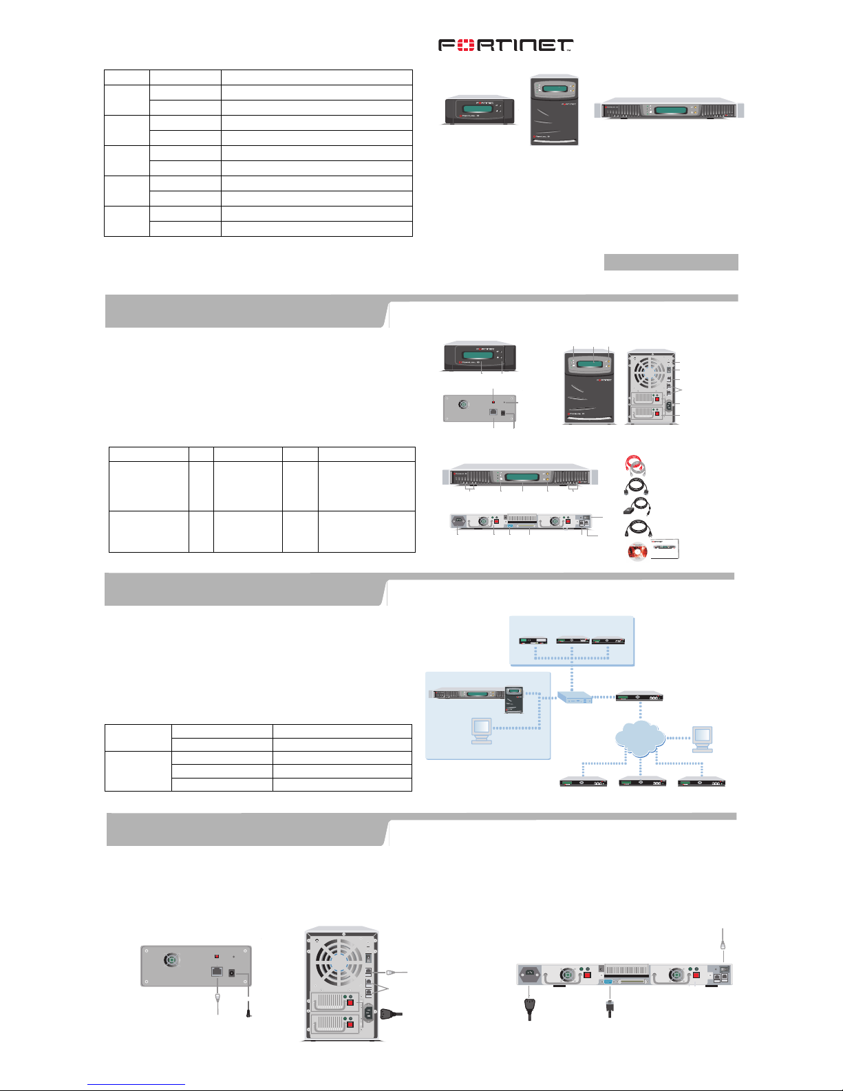
Reset
Switch
LCD
Panel
1
Setting Switches
A and B
Power
Connection
Power
Switch
LAN
Front
Back
Front
4
Back
LAN1
(Network Connection)
Reset
Switch
ATX
Redundant
Power
Supplies
Power
Connection
Power
Switch
LCD
Panel
Setting
Switches
A and B
LED indicators:
Power, Error, Network,
and Disk Access
FortiLog-100 FortiLog-400
Front
Back
LAN1
(Network
Connection)
SCSI Connector
For Tape Drive
For Future Use
RS-232
Serial
Connection
ATX Redundant
Power Supplies
Power
Connection
Power
Switch
LCD
Panel
Hard Disk
LEDs
Setting
Switches
A and B
LED indicators:
Power, Error, Network,
and Disk Access
8
Hard Disk
LEDs
FortiLog-800
Accessories for each model
LAN2 and LAN3
For Future Use
LAN2
For Future Use
Rack-Mount
Brackets
Documentation
USER MANUAL
FortiLog-100,400, 800
QuickStart Guide
Copyright 2004 Fortinet Incorporated. All rights reserved.
Trademarks
Products mentioned in this document are trademarks.
Power Cable
8
Esc Enter Esc Enter
Esc Enter
FortiGate unit
FortiGate unit
FortiGate unit
Esc Enter
Esc Enter
Management P
C
Esc Enter
FortiGate unit
Internet
Management PC
Internal Network
8
FortiLog unit
FortiGate units
FortiMail unit
4
1
CONSOLE
2
PWE
Straight-through Ethernet cable connects
to hub or switch on the network
Null modem cable connects
to serial port on management computer
Power cable connects to power outlet
FortiLog-800
FortiLog-100
Straight-through Ethernet cable connects
to hub or switch on the network
Power cable connects to power supply
LAN2 and LAN3
For Future Use
FortiLog-400
Power cable
connects to power outlet
Straight-through Ethernet cable connects
to hub or switch on the network
The FortiLog units are network appliances that you can use to collect and analyze
FortiGate log messages.
The FortiLog family includes three models. Check the model number on the front panel
of your FortiLog unit. All three models are shown in the picture here.
• FortiLog-100, desktop model with one hard drive.
• FortiLog-400, desktop model with four hard drives.
• FortiLog-800, rackmount model with four hard drives.
Connectors
Connector Type Speed Protocol Description
LAN for FortiLog-100
LAN1 for FortiLog-400
and 800
RJ-45 10/100Base-T
(FortiLog-100 and
400)
10/100/1000Base-T
(FortiLog-800)
Ethernet Connection to the network.
CONSOLE
(FortiLog-800 only)
DB-9 9600 bps RS-232
serial
Connection to the
management computer.
Provides access to the
command line interface (CLI).
FortiLog unit LED Indicators
LED State Description
Power On The FortiLog unit is powered on.
Off The FortiLog unit is powered off.
LAN
(back)
Flashing Network activities at this interface.
Off No link at the interface.
Error On The FortiLog unit is in error condition.
Off The FortiLog unit is running normally.
Network
(front)
Flashing Network activities on the FortiLog unit.
Off No network activities.
Disk
access
Flashing Hard disk activities.
Off No hard disk activities.
Check that the package contents are complete.
QuickStart Guide
Checking the package contents
1
Things you need to know before installing the FortiLog unit.
You can add the FortiLog unit to your local FortiGate network to receive log messages
from your local FortiGate units.
You can also connect the FortiLog unit to the FortiGate units remotely through the
Internet.
To connect the FortiLog unit to the FortiGate units remotely, you must configure the
DNS server and the default gateway.
To manage the FortiLog unit, you can use a computer within the local network or over
the Internet.
Factory Defaults
Administrator
account
User name: admin
Password: (none)
LAN
IP: 192.168.1.99
Netmask: 255.255.255.0
Management Access: HTTPS, Ping
Planning the installation
2
Connecting the FortiLog unit
3
Connect the FortiLog unit to a power outlet and to the network hub or switch .
• Place the unit on a stable surface.
• If you have a FortiLog-800 unit, you can also mount it in a 19-inch rack. The units require 1.5 inches (3.75 cm) clearance on each side to allow for cooling.
• Make sure the power switch on the back of the unit is turned off before connecting the power and network cables.
© Copyright 2004 Fortinet Incorporated. All rights reserved.
Trademarks
Products mentioned in this document are trademarks or registered trademarks of their respective holders.
Regulatory Compliance
FCC Class A Part 15, CE, and UL
15 November 2004
For technical support please visit http://www.fortinet.com.
FortiLog -100, 400, 800
1
8
4
01-12000-0083-20041115
Page 2
Adding an administration password
By default, the admin user does not have a password. To restrict access to the FortiLog
unit management account, add a password for the admin user account.
To add the admin user account password
1. In the web-based manager, go to System > Config > Admin .
2. For the admin user, select the Change Password icon.
3. Enter a new password in the New Password box. Reenter it in the Confirm
Password box.
4. Select OK.
Congratulations! You have set up the FortiLog unit and finished configuring the basic settings.
For more information
6
Technical documentation
For more information about FortiLog units, see:
• FortiLog online help
• FortiLog Administration Guide.
For information about FortiGate units, see:
• FortiGate online help
• FortiGate Administration Guide
• FortiGate QuickStart Guide
• Other FortiGate user guides
Technical support
Fortinet Technical Support Web site:
http://support.fortinet.com
Fortinet email support:
amer_support@fortinet.com For customers in the United States, Canada,
Mexico, Latin America and South America.
apac_support@fortinet.com For customers in Japan, Korea, China, Hong Kong,
Singapore, Malaysia, all other Asian countries, and
Australia.
eu_support@fortinet.com For customers in the United Kingdom, Scandinavia,
Mainland Europe, Africa, and the Middle East.
Using the web-based manager
For all the three FortiLog models, use the following procedure to connect to the
web-based manager for the first time. Configuration changes made with the web-based
manager are effective immediately without resetting the FortiLog unit or interrupting
service.
To connect to the web-based manager, you need:
• An Ethernet connection between the FortiLog unit and management computer.
• Internet Explorer version 4.0 or higher on the management computer.
To connect to the web-based manager
1. Connect the LAN interface of the FortiLog unit to the Ethernet port of the
management computer.
Use a cross-over Ethernet cable to connect the devices directly. Use straightthrough Ethernet cables to connect the devices through a hub or switch.
2. Configure the management computer to be on the same subnet as the FortiLog
LAN interface.
To do this, change the IP address of the management computer to 192.168.1.2 and
the netmask to 255.255.255.0.
3. To access the FortiLog web-based manager, start Internet Explorer and browse to
https://192.168.1.99 (remember to include the “s” in https://).
4. Type admin in the Name field and select Login.
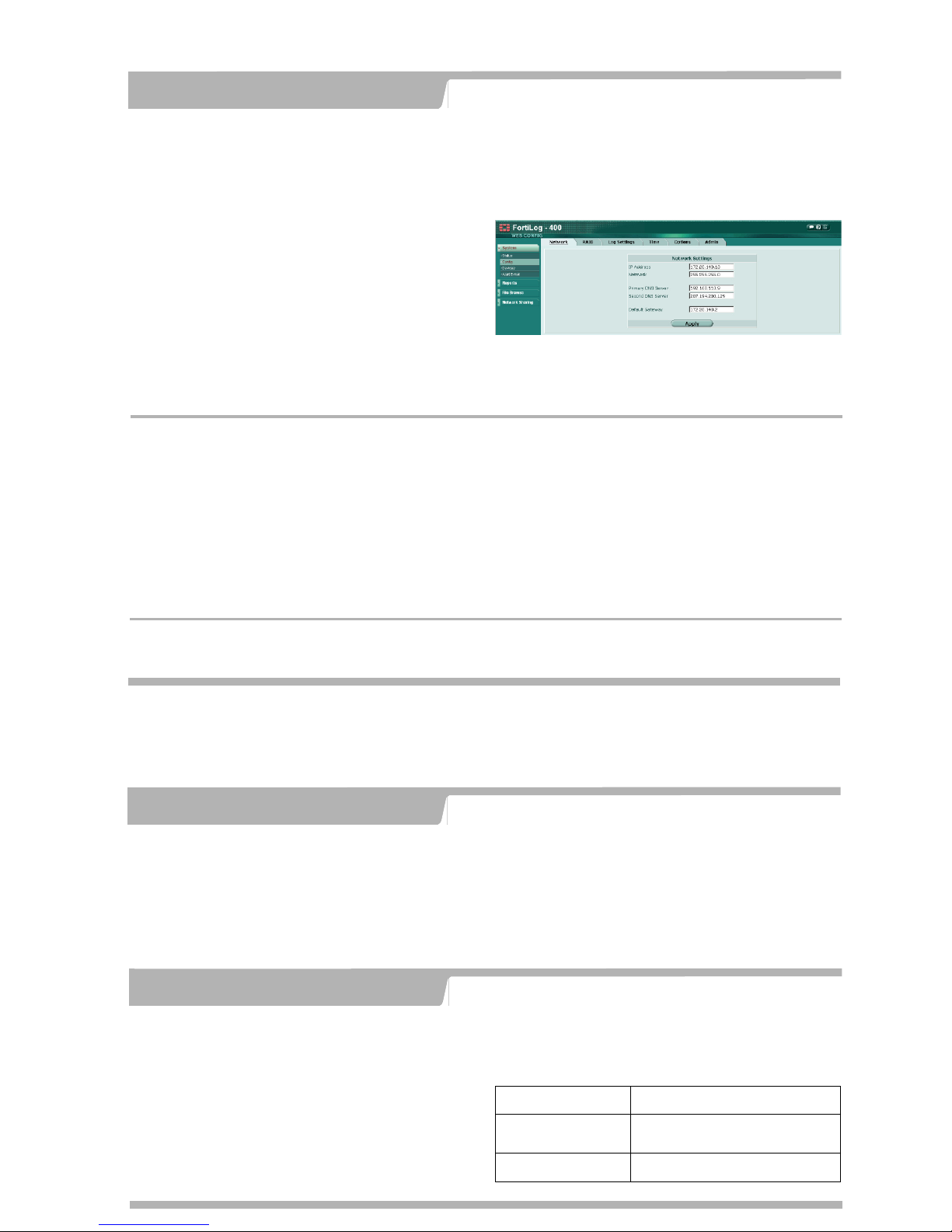
After connecting to the Web-based manager, you can configure the FortiLog unit IP
address, DNS server IP address, and default gateway to connect the FortiLog unit to
the network.
To configure the FortiLog unit using the web-based manager
1. In the web-based manager, go to System > Config > Network.
2. Enter the IP address, netmask, primary DN S server IP address, secondary DNS
server IP address (optional), and the default gateway IP address if the FortiLog unit
connects to the Internet.
Use these procedures if you experience problems operating the FortiLog unit.
Restarting the FortiLog Unit
5
Should you mistakenly change a network setting and cannot connect to the unit, reboot
the unit and try again or to set the unit back to factory defaults and start over again.
To use the web-based manager procedures
1. Go to System > Status.
2. Do one of the following:
• Select Restart to reboot the unit.
• Select Restore Factory Default to restore the factory default configuration.
To use the CLI
1. Restart the unit:
execute reboot
2. Restore factory default confi guration:
execute factoryreset
The FortiLog-800 model has serial port and you can use the null modem cable to
connect it to your management computer. The FortiLog-100 and 400 models do not
support serial cable connections. But you can use SSH to access the CLI.
To connect to the FortiLog-800 unit
1. Use a null modem cable to conne ct the FortiLog-800 serial port to the management
computer serial port.
2. Start a terminal emulation program (such as HyperTerminal) on the management
computer. Use these settings: Baud Rate (bps) 9600, Data bits 8,
Parity None, Stop bits 1, Flow Control None.
3. At the login: prompt, type admin and press Enter twice.
(The
login
prompt is preceded by the server IP address.)
After connecting to the CLI, you can configure the FortiLog-800 unit IP address, DNS
server IP address, and default gateway to connect the FortiLog-800 unit to the
network.
To configure the FortiLog unit using the CLI
1. Set the IP address and netmask of the LAN interface:
set system interface port1 mode static ip <IP_address> <netmask>
2. Confirm that the address is correct:
get system interface
3. Set the primary DNS server IP address:
set system dns primary <IP_address>
4. Optionally set the secondary DNS server IP address:
set system dns secondary <IP_address>
5. Set the default gateway:
set system route number <route_no> dst 0.0.0.0 0.0.0.0 gw1 <gw_ip>
Using the CLI
Use the web-based manager or the Command Line Interface (CLI) to configure the FortiLog unit
IP address, netmask, DNS server IP address, and default gateway IP address.
Remember to change the password.
Configuring the FortiLog unit
4
Using the CLI
Using the front panel buttons and LCD
You can use the front panel buttons to set up the FortiLog unit’s IP address, netmask,
and default gateway.
 Loading...