

Fortinet FortiGate-5001SX, FortiGate-5001, FortiGate-5001A, FortiGate-5001FA2, FortiGate-5050 Introduction Manual
...Page 1
1311975312468101214
5140
FILTER
12
0
12
PSU A
PSU B
FortiGate-5000 Series
Introduction
5140SAP
SERIAL 1 SERIAL 2 ALARM
L
2
1
3
R
A
R
R
R
R
O
C
T
O
I
J
E
E
E
E
IN
IT
S
S
S
A
S
R
U
U
U
M
E
M
C
R
USB
5
4
3
5000SM
ETH1
ETH0
10/100
10/100
link/Act
link/Act
ETH0
Service
RESET
STATUS
Hot Swap
2
1
5000SM
SMC
ETH1
ETH0
2
CONSOLE
ACC
PWR
CONSOLE
ACC
PWR
CONSOLE
ACC
PWR
ETH
O
MANAGEMENT
ETH
O
MANAGEMENT
10/100
ETH0
Service
link/Act
STATUS
10/100
RESET
link/Act
1 2 3 4 5 6 7 8
USB
1 2 3 4 5 6 7 8
USB
1 2 3 4 5 6 7 8
RS232ZRE0ZRE1ZRE2
SYSTEM
CONSOLE
RS232ZRE0ZRE1ZRE2
SYSTEM
CONSOLE
5050SAP
SERIAL
Hot Swap
1
ALARM
STA IPM
STA IPM
STA IPM
OKCLK
INTEXT
1110
1110
9876543210
9876543210
FLT
HOT SWAP
RESET
ZRE
LED MODE
FLT
OKCLK
INTEXT
FLT
HOT SWAP
RESET
ZRE
LED MODE
FLT
5000SM
10/100
ETH0
Service
link/Act
ETH1
SERIAL
10/100
2
ETH0
link/Act
POWER
SMC
STATUS
Hot Swap
RESET
1
E1
1514
1312
E2
E1
1514
1312
E2
5000SM
ETH1
ETH0
10/100
10/100
link/Act
link/Act
ETH0
Service
RESET
STATUS
Hot Swap
USB
CONSOLE
ACC
PWR
ACT
LINK
BASE
ACT
FABRIC
LINK
CONSOLE
1 2 3 4 5 6 7 8
USB USB
OOS ACC STATUS
3 412 56
STA IPM
78
IPM
FAN TRAY FAN TRAYFAN TRAY
The most recent versions of this and all FortiGate-5000 series documents are available from the FortiGate-5000
page of the Fortinet Technical Documentation web site (http://docs.forticare.com).
Visit http://support.fortinet.com to register your FortiGate-5000 Series product. By registering you can receive
product updates, technical support, and FortiGuard services.
FortiGate-5000 Series Introduction
01-30000-83466-20090108
Page 2

FortiGate-5000 Series Introduction
8 January 2009
01-30000-83466-20090108
© Copyright 2009 Fortinet, Inc. All rights reserved. No part of this
publication including text, examples, diagrams or illustrations may be
reproduced, transmitted, or translated in any form or by any means,
electronic, mechanical, manual, optical or otherwise, for any purpose,
without prior written permission of Fortinet, Inc.
Trademarks
Fortinet, FortiGate and FortiGuard are registered trademarks and
Dynamic Threat Prevention System (DTPS), APSecure, FortiASIC,
FortiBIOS, FortiBridge, FortiClient, FortiGate, FortiGate Unified Threat
Management System, FortiGuard-Antispam, FortiGuard-Antivirus,
FortiGuard-Intrusion, FortiGuard-Web, FortiLog, FortiAnalyzer,
FortiManager, FortiOS, FortiPartner, FortiProtect, FortiReporter,
FortiResponse, FortiShield, and FortiVoIP, are trademarks of Fortinet, Inc.
in the United States and/or other countries. The names of actual
companies and products mentioned herein may be the trademarks of
their respective owners.
Page 3

Contents
Contents
Introduction .............................................................................................. 7
Revision history .............................................................................................................. 7
About the FortiGate-5000 series chassis...................................................................... 8
FortiGate-5140 chassis............................................................................................... 8
FortiGate-5050 chassis............................................................................................... 8
FortiGate-5020 chassis............................................................................................... 9
About the FortiGate-5000 series boards....................................................................... 9
FortiGate-5001A security system ............................................................................... 9
FortiGate-RTM-XB2 module ..................................................................................... 10
FortiGate-5005FA2 security system ......................................................................... 10
FortiGate-5001FA2 security system ......................................................................... 10
FortiGate-5001SX security system ........................................................................... 10
FortiSwitch-5003A system ........................................................................................ 10
FortiSwitch-5003 system .......................................................................................... 11
FortiGate-5005-DIST security system ...................................................................... 11
FortiController-5208 system ..................................................................................... 11
Warnings and cautions................................................................................................. 11
About Data Center DC power....................................................................................... 13
Fortinet documentation ................................................................................................ 13
Fortinet Tools and Documentation CD ..................................................................... 13
Fortinet Knowledge Center ....................................................................................... 13
Comments on Fortinet technical documentation ...................................................... 13
Customer service and technical support.................................................................... 13
Register your Fortinet product .................................................................................... 14
FortiGate-5140-R chassis ...................................................................... 15
FortiGate-5140 chassis front panel ............................................................................. 16
FortiGate-5140 chassis back panel ............................................................................. 17
Physical description of the FortiGate-5140 chassis .................................................. 18
FortiGate-5140 chassis.......................................................................... 19
FortiGate-5140 chassis front panel ............................................................................. 19
FortiGate-5140 chassis back panel ............................................................................. 20
Physical description of the FortiGate-5140 chassis .................................................. 22
FortiGate-5050-R chassis ...................................................................... 23
FortiGate-5050 front panel ........................................................................................... 24
FortiGate-5050 back panel ........................................................................................... 25
Physical description of the FortiGate-5050 chassis .................................................. 26
FortiGate-5000 Series Introduction
01-30000-83466-20090108 3
http://docs.fortinet.com/ • Feedback
Page 4

Contents
FortiGate-5050 chassis.......................................................................... 27
FortiGate-5050 front panel ........................................................................................... 28
FortiGate-5050 back panel ........................................................................................... 28
Physical description of the FortiGate-5050 chassis .................................................. 29
FortiGate-5020 chassis.......................................................................... 31
FortiGate-5020 front panel ........................................................................................... 31
FortiGate-5020 back panel ........................................................................................... 32
Physical description of the FortiGate-5020 chassis .................................................. 32
FortiGate-5001A security system ......................................................... 33
Front panel LEDs and connectors............................................................................... 34
LEDs ......................................................................................................................... 35
Connectors ............................................................................................................... 36
Base backplane communication ................................................................................. 36
Fabric backplane communication ............................................................................... 36
FortiGate-RTM-XB2.................................................................................................. 37
AMC modules ................................................................................................................ 37
FortiGate-RTM-XB2 system................................................................... 39
Front panel LED ............................................................................................................ 40
Fabric backplane 10-gigabit communication ............................................................. 40
FortiGate-5005FA2 security system ..................................................... 41
Front panel LEDs and connectors............................................................................... 42
LEDs ......................................................................................................................... 42
Connectors ............................................................................................................... 43
Accelerated packet forwarding and policy enforcement .......................................... 43
FA2 interfaces and active-active HA performance ................................................... 44
Base backplane gigabit communication..................................................................... 44
FortiGate-5005-DIST security system ......................................................................... 44
FortiGate-5001FA2-LENC security system .......................................... 45
Front panel LEDs and connectors............................................................................... 46
LEDs ......................................................................................................................... 46
Connectors ............................................................................................................... 47
Accelerated packet forwarding and policy enforcement .......................................... 47
FA2 interfaces and active-active HA performance ................................................... 48
Base backplane gigabit communication..................................................................... 48
4 01-30000-83466-20090108
FortiGate-5000 Series Introduction
http://docs.fortinet.com/ • Feedback
Page 5

Contents
FortiGate-5001SX security system ....................................................... 49
Front panel LEDs and connectors............................................................................... 50
LEDs ......................................................................................................................... 50
Connectors ............................................................................................................... 51
Base backplane gigabit interfaces .............................................................................. 51
FortiSwitch-5003A system .................................................................... 53
Front panel LEDs and connectors............................................................................... 54
LEDs ......................................................................................................................... 55
Base channel interfaces ........................................................................................... 56
Fabric channel interfaces.......................................................................................... 57
Front panel connectors ............................................................................................. 58
FortiSwitch-5003A configurations............................................................................... 58
Base and fabric gigabit switching within a chassis ................................................... 58
Fabric 10-gigabit switching within a chassis ............................................................. 59
Layer-2 link aggregation and redundancy configurations ......................................... 60
FortiSwitch-5003 system ....................................................................... 61
Front panel LEDs and connectors............................................................................... 61
LEDs ......................................................................................................................... 62
About the ZRE network activity LEDs....................................................................... 63
Connectors ............................................................................................................... 64
Base backplane communications ............................................................................... 64
The FortiGate-5005-DIST security system ........................................... 67
Basic FortiGate security system configuration ......................................................... 67
FortiController-5208 I/O boards ................................................................................... 68
FortiGate-5005FA2 worker boards .............................................................................. 69
FortiGate-5005-DIST security system chassis ........................................................... 70
FortiGate-5140 chassis............................................................................................. 70
FortiGate-5050 chassis............................................................................................. 71
FortiGate-5005-DIST interface names ......................................................................... 71
FortiController-5208 system ................................................................. 73
Front panel LEDs and connectors............................................................................... 74
LEDs ......................................................................................................................... 74
Connectors ............................................................................................................... 75
Backplane gigabit interfaces ....................................................................................... 76
FortiGate-5000 Series Introduction
01-30000-83466-20090108 5
http://docs.fortinet.com/ • Feedback
Page 6

Contents
6 01-30000-83466-20090108
FortiGate-5000 Series Introduction
http://docs.fortinet.com/ • Feedback
Page 7

Introduction Revision history
Introduction
This FortiGate-5000 Series Introduction is a high-level guide to all three
FortiGate-5000 series chassis and the boards that you can install in them.
This chapter includes the following topics:
• Revision history
• About the FortiGate-5000 series chassis
• About the FortiGate-5000 series boards
• Warnings and cautions
• Fortinet documentation
• Customer service and technical support
• Register your Fortinet product
Revision history
Table 1: Revision History
Version Description of changes
01-30003-0378-20061207 New version.
01-30004-0378-20070201 Corrected “FortiGate-5020 chassis” on page 31 and
“FortiGate-5005FA2 security system” on page 41 to
document that FortiGate-5005FA2 boards can be
installed in a FortiGate-5020 chassis. Added
“Register your Fortinet product” on page 14. Added
“FA2 interfaces and active-active HA performance”
on page 44 and “FA2 interfaces and active-active HA
performance” on page 48. More minor changes and
fixes throughout the document.
01-30000-0378-20070615 Added the following sections:
• “FortiGate-5005-DIST security system” on
page 11
• “FortiController-5208 system” on page 11
• “The FortiGate-5005-DIST security system” on
page 67
• “FortiController-5208 system” on page 73
01-30000-378-20080603 Added “FortiGate-5001A security system” on
page 33.
Terminology change: “module” changed to “board”
for all FortiGate-5000 series boards.
01-30000-83466-20081023 Updated “FortiGate-5001A security system” on
page 33 to include the FortiGate-5001A-SW board.
Added the following sections:
• “FortiGate-RTM-XB2 system” on page 39
• “FortiSwitch-5003A system” on page 53
FortiGate-5000 Series Introduction
01-30000-83466-20090108 7
Page 8
About the FortiGate-5000 series chassis Introduction
Table 1: Revision History
Version Description of changes
01-30000-83466-20081023 Added information about both FortiGate-5140 and
both FortiGate-5050 chassis versions:
• “FortiGate-5140-R chassis” on page 15
• “FortiGate-5140 chassis” on page 19
• “FortiGate-5050-R chassis” on page 23
• “FortiGate-5050 chassis” on page 27
About the FortiGate-5000 series chassis
The FortiGate-5000 series Security Systems are chassis-based systems that
MSSPs and large enterprises can use to provide subscriber security services
such as firewall, VPN, antivirus protection, spam filtering, web filtering and
intrusion prevention (IPS). The wide variety of system configurations available
with FortiGate-5000 series provide flexibility to meet the changing needs of
growing high performance networks. The FortiGate-5000 series chassis support
multiple hot-swappable FortiGate-5000 series boards and power supplies. This
modular approach provides a scalable, high-performance and failure-proof
solution.
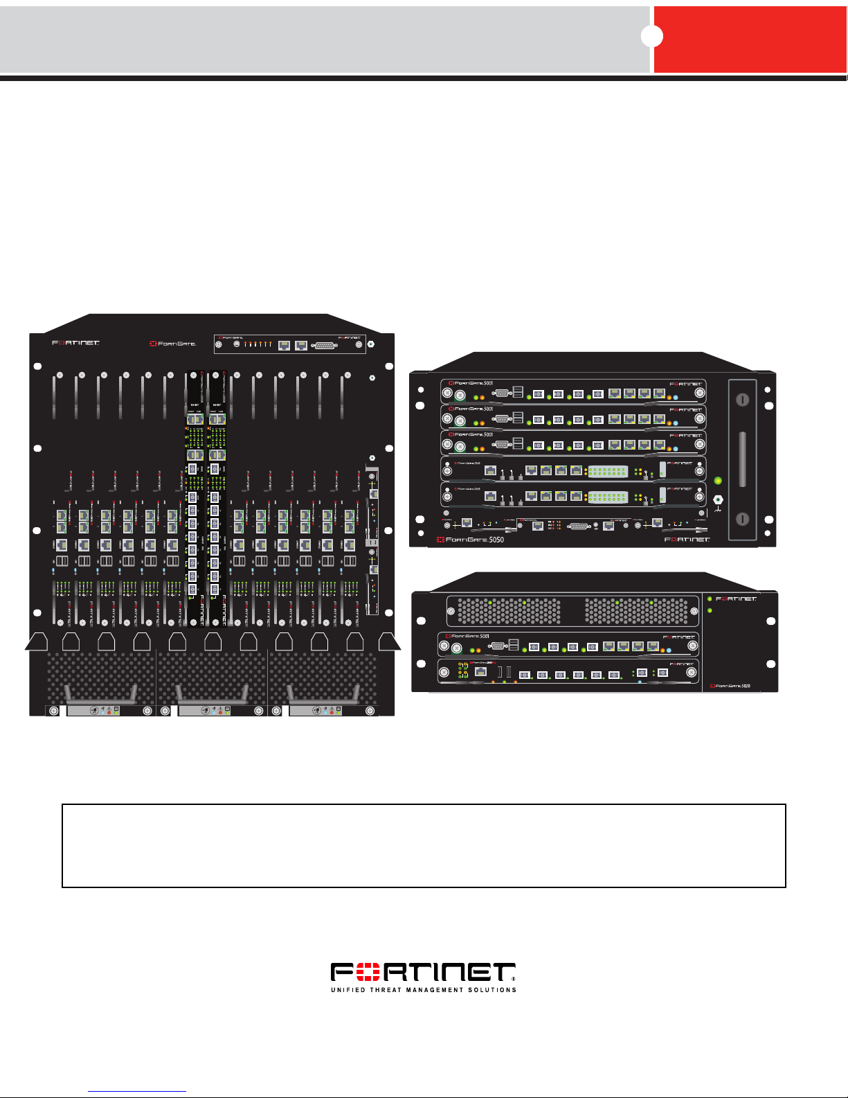
FortiGate-5140 chassis
You can install up to 14 FortiGate-5000 series
boards in the 14 slots of the FortiGate-5140
ATCA chassis. The FortiGate-5140 is a 12U
chassis that contains two redundant hot
swappable DC power entry modules that
connect to -48 VDC Data Center DC power. The
FortiGate-5140 chassis also includes three hot
swappable cooling fan trays.
Fortinet supplies two FortiGate-5140 chassis
with very similar features. For details see:
• “FortiGate-5140-R chassis” on page 15
• “FortiGate-5140 chassis” on page 19
FortiGate-5050 chassis
You can install up to five FortiGate-5000 series
boards in the five slots of the FortiGate-5050
ATCA chassis. The FortiGate-5050 is a 5U
chassis that contains two redundant DC power
connections that connect to -48 VDC Data
Center DC power. The FortiGate-5050 chassis
also includes a hot swappable cooling fan tray.
Fortinet supplies two FortiGate-5050 chassis with very similar features. For details
see:
5140SAP
1311975312468101214
0
CONSOLE
5
ACC
PWR
CONSOLE
4
ACC
PWR
CONSOLE
ACC
PWR
3
ETH
O
2
MANAGEMENT
ETH
O
1
MANAGEMENT
5000SM
10/100
SMC
ETH0
Service
link/Act
ETH1
STATUS
10/100
RESET
ETH0
link/Act
2
5140
FILTER
FAN TRAY FAN TRAYFAN TRAY
12
USB
1 2 3 4 5 6 7 8
USB
1 2 3 4 5 6 7 8
USB
1 2 3 4 5 6 7 8
RS232ZRE0ZRE1ZRE2
SYSTEM
CONSOLE
RS232ZRE0ZRE1ZRE2
SYSTEM
CONSOLE
5050SAP
SERIAL
Hot Swap
1
ALARM
SERIAL 1 SERIAL 2 ALARM
USER2
USER1
USER3
MINOR
MAJOR
CRITICAL
RESET
STAIPM
STAIPM
STAIPM
OKCLK
INTEXT
FLT
E1
9876543210
1514
1312
1110
HOT SWAP
RESET
ZRE
LED MODE
E2
FLT
E1
OKCLK
INTEXT
FLT
9876543210
1514
1312
1110
HOT SWAP
RESET
ZRE
LED MODE
E2
FLT
5000SM
10/100
SMC
ETH0
Service
link/Act
ETH1
SERIAL
STATUS
Hot Swap
10/100
RESET
2
ETH0
link/Act
5000SM
ETH1
ETH0
10/100
10/100
link/Act
link/Act
ETH0
Service
RESET
STATUS
Hot Swap
12
5000SM
ETH1
ETH0
10/100
10/100
link/Act
link/Act
ETH0
Service
RESET
STATUS
Hot Swap
POWER
1
• “FortiGate-5050-R chassis” on page 23
• “FortiGate-5050 chassis” on page 27
FortiGate-5000 Series Introduction
8 01-30000-83466-20090108
Page 9
Introduction About the FortiGate-5000 series boards
PSU A
PSU B
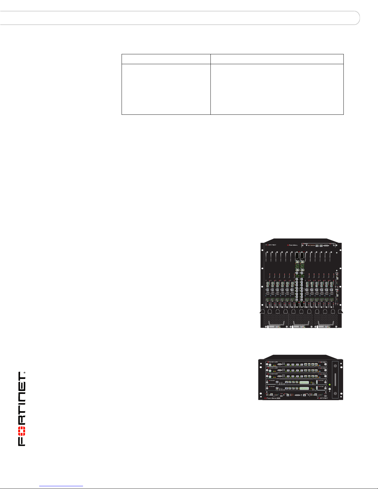
FortiGate-5020 chassis
You can install one or two FortiGate-5000 series
boards in the two slots of the FortiGate-5020
USB
1 2 3 4 5 6 7 8
ATCA chassis. The FortiGate-5020 is a 4U
chassis that contains two redundant AC to DC
CONSOLE
ACC
PWR
ACT
USB USB
LINK
BASE
ACT
FABRIC
LINK
CONSOLE
OOS ACC STATUS
3 412 56
78
IPM
STAIPM
power supplies that connect to AC power. The
FortiGate-5020 chassis also includes an internal cooling fan tray. For details about
the FortiGate-5020 chassis, see “FortiGate-5020 chassis” on page 31.
About the FortiGate-5000 series boards
Each FortiGate-5000 series board is a standalone FortiGate security system that
can also function as part of a FortiGate HA cluster. All FortiGate-5000 series
boards are also hot swappable. All FortiGate-5000 series units are high capacity
security systems with multiple gigabit interfaces, multiple virtual domain capacity,
and other high end FortiGate features.
FortiGate-5001A security system
The FortiGate-5001A board is an
independent high-performance
FortiGate security system with
two front panel gigabit ethernet interfaces, two base backplane gigabit interfaces,
and two fabric backplane gigabit interfaces. Use the front panel interfaces for
connections to your networks and the backplane interfaces for communication
between FortiGate-5000 series boards over the ACTA chassis backplane. The
fabric interfaces are reserved for future 10-gigabit operation but can be used now
for board to board 1-gigabit operation. In FortiGate-5140 and FortiGate-5050
chassis you must install a FortiSwitch-5003 board or another backplane switching
product to support backplane communication. For details about the
FortiGate-5001A security system, see “FortiGate-5001A security system” on
page 33.
The FortiGate-5001A-DW front panel includes a double-width Advanced
Mezzanine Card (AMC) opening. You can install a supported FortiGate AMC
Double width Module (ADM) module such as the FortiGate-ADM-XB2 or the
FortiGate-ADM-FB8 in the AMC opening. The FortiGate-ADM-XB2 adds two
accelerated 10-gigabit interfaces to the FortiGate board and the FortiGateADM-FB8 adds 8 accelerated 1 gigabit interfaces.
The FortiGate-5001A-SW (single-width) includes a single-width AMC opening.
You can install a supported FortiGate AMC Single width Module (ASM) such as
the FortiGate-ASM-FB4 or the FortiGate-ASM-S08 in the AMC opening. The
FortiGate-ASM-FB4 adds four accelerated 1-gigabit interfaces to the FortiGate
board and the FortiGate-ADM-S08 adds a removable hard disk that you can use
to store log files and content archives.
FortiGate-5000 Series Introduction
01-30000-83466-20090108 9
Page 10
About the FortiGate-5000 series boards Introduction
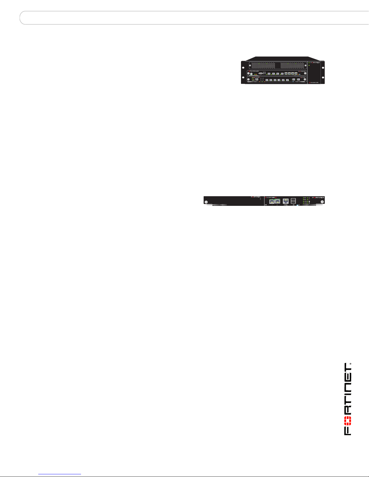
FortiGate-RTM-XB2 module
The FortiGate-RTM-XB2 system
is a rear transition module (RTM)
that provides two 10-gigabit fabric
backplane interfaces and NP2 processor acceleration for FortiGate-5001A boards
installed in FortiGate-5140 and FortiGate-5050 chassis. For details about the
FortiGate-RTM-XB2 system, see “FortiGate-RTM-XB2 system” on page 39
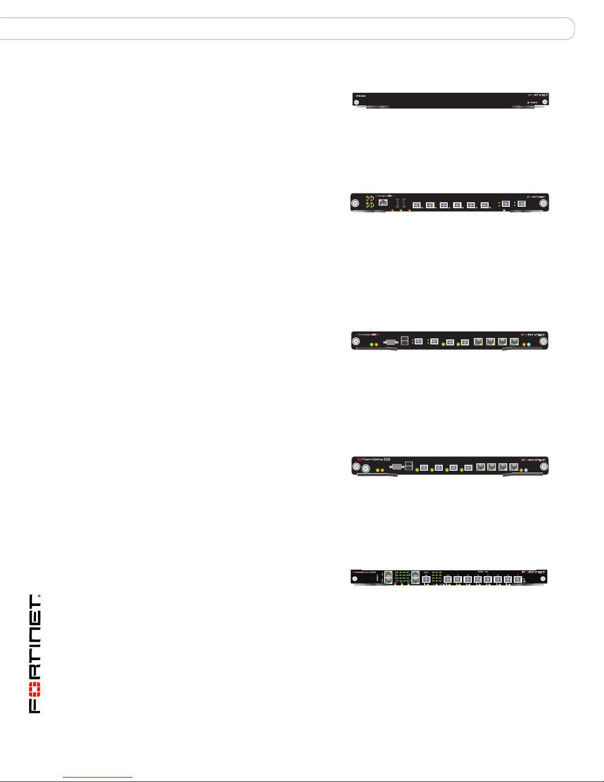
FortiGate-5005FA2 security system
The FortiGate-5005FA2 board is
an independent high-performance
ACT
LINK
ACT
LINK
FortiGate security system with
eight gigabit ethernet interfaces. The FortiGate
features including 802.1Q VLANs and multiple virtual domains. Two of the
FortiGate-5005FA2 interfaces (port7 and port8) include Fortinet technology to
accelerate small packet performance. FortiGate-5005FA2 boards also function as
worker boards in a FortiGate-5005-DIST security system. For details about the
FortiGate-5005FA2 board, see “FortiGate-5005FA2 security system” on page 41.
USB USB
BASE
FABRIC
CONSOLE
OOS ACC STATUS
3 412 56
-5005FA2 board supports high-end
78
IPM
FortiGate-5001FA2 security system
The FortiGate-5001FA2 security
system is an independent highperformance FortiGate security
system with eight gigabit ethernet interfaces. The FortiGate-5001FA2 board is
similar to the FortiGate-5001SX board except that two of the FortiGate-5001FA2
interfaces include Fortinet technology to accelerate small packet performance. For
details about the FortiGate-5001FA2 board, see “FortiGate-5001FA2-LENC
security system” on page 45.
FortiGate-5001SX security system
The FortiGate-5001SX security
system is an independent highperformance FortiGate security
system with eight gigabit ethernet interfaces. The FortiGate
supports high-end features including 802.1Q VLANs and multiple virtual domains.
For details about the FortiGate-5001SX security system, see “FortiGate-5001SX
security system” on page 49.
FortiSwitch-5003A system
The FortiSwitch-5003A system
provides 10/1-gigabit fabric
backplane channel layer-2
switching and 1-gigabit base backplane channel layer-2 switching in a dual star
architecture for the FortiGate-5140 and FortiGate-5050 chassis. The FortiGate
board provides a total capacity of 200 Gigabits per second (Gbps) throughput.For
details about the FortiSwitch-5003A system, see “FortiGate-5001SX security
system” on page 49.
USB
CONSOLE
1 2
USB
CONSOLE
ACC
PWR
ACC
PWR
3 4
5 6 7 8
1 2 3 4 5 6 7 8
STA IPM
STA IPM
-5001SX board
FortiGate-5000 Series Introduction
10 01-30000-83466-20090108
Page 11

Introduction Warnings and cautions
MANAGEMENT
SYSTEM
E1
ZRE
LED MODE
1514
1312
1110
9876543210
E0
OKCLK
INTEXT
FLT
HOT SWAP
RESET
FLT
CONSOLE
ETH
O
RS232ZRE0ZRE1ZRE2
1
2
2
3
4
5
SMC
1
SMC
POWER
PAYLOAD OPERATION
STATUS
IPM
X 1
X 2
1/2 3/4 D15/D16 C15/C16
1
2
3
4
5
6
7
8
9
10
11
12
D
13
14
15
16
D
1
2
3
4
5
6
7
8
9
10
11
12
C
13
14
15
16
C
10/100/1000 MBPS ETHERNET ACTIVITY
DATA CONTROL
1
2
3
4
MANAGEMENT
COM 1 COM 2
X 1 X 2
FortiSwitch-5003 system
The FortiSwitch-5003 system
provides base backplane
communication between
FortiGate security boards installed in FortiGate-5140 or FortiGate-5050 chassis.
Base backplane communication can be used for HA heartbeat communication
and for data communication. The FortiSwitch-5003 board can also provide HA
heartbeat and data communication between chassis. The FortiSwitch-5003 board
is only used in FortiGate-5140 and FortiGate-5050 chassis. For details about the
FortiSwitch-5003 board, see “FortiSwitch-5003 system” on page 61.
FortiGate-5005-DIST security system
The FortiGate-5005-DIST security system is
very similar to a single FortiGate unit, but with
much higher capacity and with support for
failover protection and scalability. The
FortiGate-5005-DIST security system consists
of a FortiGate-5050 or FortiGate-5140 chassis
with one or two Input/Output or I/O boards
(FortiController-5208 boards) and one or more worker boards (FortiGate-5005FA2
boards running in DIST mode). The I/O boards provide 10 gigabit and 1gigabit
network connections and distribute traffic to the worker boards. The worker
boards provide FortiGate security system functions including firewall, VPN, IPS,
antivirus, antispam, and so on. For details about the FortiGate-5005-DIST security
system, see “The FortiGate-5005-DIST security system” on page 67.
FortiController-5208 system
An integral part of a
FortiGate-5005-DIST Security
System, the FortiController-5208
board provides all Fortigate-5005-DIST 10gigabit and 1 gigabit network
interfaces. The FortiContro0ller-5208 board also provides the management
interface to the FortiGate-5005-DIST system and controls backplane
communication between all FortiGate-5005-DIST components.
You can create a FortiGate-5005-DIST high-throughput multi-threat network
security system using one or two FortiGate boards and multiple FortiGate-5005
boards in a FortiGate-5050 or FortiGate-5140 chassis. A FortiGate-5020 chassis
cannot be used to create a FortiGate-5005-DIST system. Functionally, one or two
FortiGate boards using the processing power of multiple FortiGate-5005 boards
function much like a single FortiGate unit, but with far greater capacity. For details
about the FortiController-55208 board, see “FortiController-5208 system” on
page 73.
ACT
USB USB
LINK
BASE
ACT
FABRIC
LINK
CONSOLE
ACT
LINK
BASE
ACT
FABRIC
LINK
CONSOLE
ACT
LINK
BASE
ACT
FABRIC
LINK
CONSOLE
ACT
LINK
BASE
ACT
FABRIC
LINK
CONSOLE
X 1
X 2
5000SM
10/100
ETH0
Service
link/Act
ETH1
10/100
RESET
ETH0
link/Act
3 412 56
OOS ACC STATUS
USB USB
3 412 56
OOS ACC STATUS
USB USB
3 412 56
OOS ACC STATUS
USB USB
3 412 56
OOS ACC STATUS
DATA CONTROL
9
5
9
1
13
5
1
13
X 1 X 2
10
6
10
2
14
6
2
14
11
7
11
3
15
7
3
15
C
D
12
8
12
4
16
8
4
16
C
D
10/100/1000 MBPS ETHERNET ACTIVITY
PAYLOAD OPERATION
STATUS
5050SAP
SERIAL
STATUS
Hot Swap
1
ALARM
1/2 3/4 D15/D16 C15/C16
78
IPM
78
IPM
78
IPM
78
IPM
1
MANAGEMENT
COM 1 COM 2
2
3
4
IPM
5000SM
10/100
ETH0
Service
link/Act
ETH1
SERIAL
STATUS
Hot Swap
10/100
RESET
2
ETH0
link/Act
Warnings and cautions
Only trained and qualified personnel should be allowed to install or
maintain FortiGate-5000 series equipment. Read and comply with all
warnings, cautions and notices in this document.
FortiGate-5000 Series Introduction
01-30000-83466-20090108 11
Page 12

Warnings and cautions Introduction
!
!
CAUTION: Risk of Explosion if Battery is replaced by an Incorrect Type. Dispose
of Used Batteries According to the Instructions.
Caution: You should be aware of the following cautions and warnings before
installing FortiGate-5000 series hardware
• Turning off all power switches may not turn off all power to the FortiGate-5000
series equipment. Some circuitry in the FortiGate-5000 series equipment may
continue to operate even though all power switches are off.
• Many FortiGate-5000 components are hot swappable and can be installed or
removed while the power is on. But some of the procedures in this document
may require power to be turned off and completely disconnected. Follow all
instructions in the procedures in this document that describe disconnecting
FortiGate-5000 series equipment from power sources, telecommunications
links and networks before installing, or removing FortiGate-5000 series
components, or performing other maintenance tasks. Failure to follow the
instructions in this document can result in personal injury or equipment
damage.
• Install FortiGate-5000 series chassis at the lower positions of a rack to avoid
making the rack top-heavy and unstable.
• Do not insert metal objects or tools into open chassis slots.
• Electrostatic discharge (ESD) can damage FortiGate-5000 series equipment.
Only perform the procedures described in this document from an ESD
workstation. If no such station is available, you can provide some ESD
protection by wearing an anti-static wrist strap and attaching it to an available
ESD connector such as the ESD sockets provided on FortiGate-5000 series
chassis.
• Make sure all FortiGate-5000 series components have reliable grounding.
Fortinet recommends direct connections to the building ground.
• If you install a FortiGate-5000 series component in a closed or multi-unit rack
assembly, the operating ambient temperature of the rack environment may be
greater than room ambient. Make sure the operating ambient temperature
does not exceed Fortinet’s maximum rated ambient temperature.
• Installing FortiGate-5000 series equipment in a rack should be such that the
amount of airflow required for safe operation of the equipment is not
compromised.
• FortiGate-5000 series chassis should be installed by a qualified electrician.
• FortiGate-5000 series equipment shall be installed and connected to an
electrical supply source in accordance with the applicable codes and
regulations for the location in which it is installed. Particular attention shall be
paid to use of correct wire type and size to comply with the applicable codes
and regulations for the installation / location. Connection of the supply wiring to
the terminal block on the equipment may be accomplished using Listed wire
compression lugs, for example, Pressure Terminal Connector made by Ideal
Industries Inc. or equivalent which is suitable for AWG 10. Particular attention
shall be given to use of the appropriate compression tool specified by the
compression lug manufacturer, if one is specified.
FortiGate-5000 Series Introduction
12 01-30000-83466-20090108
Page 13

Introduction About Data Center DC power
About Data Center DC power
The FortiGate-5140 and FortiGate-5050 chassis are designed to be installed in a
Data Center or similar location that has available -48VDC power. Fortinet expects
that most FortiGate-5140 or FortiGate-5050 customers will be installing their
FortiGate equipment in a data center or similar location that is already equipped
with a -48VDC power system that provides power to existing networking or
telecom equipment. The FortiGate-5140 and FortiGate-5050 chassis are
designed to be connected directly to this DC power system.
In this document, Data Center DC power refers to a -48VDC power system that is
already available at the location at which the FortiGate-5140 or FortiGate-5050
chassis is being installed.
Fortinet documentation
The most up-to-date publications and previous releases of Fortinet product
documentation are available from the Fortinet Technical Documentation web site
at http://docs.forticare.com.
Fortinet Tools and Documentation CD
All Fortinet documentation is available from the Fortinet Tools and Documentation
CD shipped with your Fortinet product. The documents on this CD are current at
shipping time. For up-to-date versions of Fortinet documentation see the Fortinet
Technical Documentation web site at http://docs.forticare.com.
Fortinet Knowledge Center
Additional Fortinet technical documentation is available from the Fortinet
Knowledge Center. The knowledge center contains troubleshooting and how-to
articles, FAQs, technical notes, and more. Visit the Fortinet Knowledge Center at
http://kc.forticare.com.
Comments on Fortinet technical documentation
Please send information about any errors or omissions in this document, or any
Fortinet technical documentation, to techdoc@fortinet.com.
Customer service and technical support
Fortinet Technical Support provides services designed to make sure that your
Fortinet systems install quickly, configure easily, and operate reliably in your
network.
Please visit the Fortinet Technical Support web site at http://support.fortinet.com
to learn about the technical support services that Fortinet provides.
FortiGate-5000 Series Introduction
01-30000-83466-20090108 13
Page 14

Register your Fortinet product Introduction
Register your Fortinet product
Register your Fortinet product to receive Fortinet customer services such as
product updates and technical support. You must also register your product for
FortiGuard services such as FortiGuard Antivirus and Intrusion Prevention
updates and for FortiGuard Web Filtering and AntiSpam.
Register your product by visiting http://support.fortinet.com and selecting Product
Registration.
To register, enter your contact information and the serial numbers of the Fortinet
products that you or your organization have purchased. You can register multiple
Fortinet products in a single session without re-entering your contact information.
FortiGate-5000 Series Introduction
14 01-30000-83466-20090108
Page 15

FortiGate-5140-R chassis
FortiGate-5140-R chassis
You can install up to 14 FortiGate-5000 series boards in the 14 front panel slots of the
FortiGate-5140 ATCA chassis. The FortiGate-5140 is a 12U chassis that contains two
redundant hot swappable DC power entry modules that connect to -48 VDC Data Center
DC power. The FortiGate-5140 chassis also includes three hot swappable cooling fan
trays and a front accessible air filter. If all 14 front panel slots contain FortiGate-5005A2,
FortiGate-5001SX, or FortiGate-5001FA2 boards the FortiGate-5140 chassis provides a
total of 112 FortiGate gigabit ethernet interfaces. If all 14 slots contain FortiGate-5001A
boards the FortiGate-5140 chassis supports 28 1-Gigabit ethernet FortiGate interfaces. If
you add FortiGate-ADM-XB2 modules to the FortiGate-5001A boards the FortiGate-5140
chassis supports another 28 10-Gigabit interfaces.
You can also install a FortiSwitch-5003A or FortiSwitch-5003 board in the FortiGate-5140
chassis to provide base backplane communications. Base backplane communications can
be used for HA heartbeat communications and for data communications. You can add a
second FortiSwitch-5003A or FortiSwitch-5003 board for redundancy. FortiSwitch-5003A
boards can also provide fabric backplane communication using the FortiGate-5140 fabric
backplane channels.
You can mix and match any combination of FortiGate-5000 series boards in the
FortiGate-5140 chassis. For example, you could install four FortiGate-5005FA2 boards,
four FortiGate-5001SX boards, and four FortiGate-5001FA2 boards. You can also install
FortiController-5208 and FortiGate-5005FA2 boards in a FortiGate-5140 chassis to create
a FortiGate-5005-DIST security system.
Some of the boards installed in a FortiGate-5140 chassis can be operating in a FortiGate
HA cluster and some can be operating as standalone FortiGate units. You can also
operate multiple HA clusters and standalone FortiGate units in a single FortiGate-5140
chassis. You can also use FortiSwitch-5003A or FortiSwitch-5003 boards to operate HA
clusters consisting of FortiGate-5000 series boards installed in multiple FortiGate-5000
chassis. You can also use FortiSwitch-5003A boards for fabric data communication
between chassis.
The FortiGate-5140 chassis requires -48VDC Data Center DC power. If DC power is not
available you can install a FortiGate-5053 power converter tray (purchased separately)
with FortiGate-5140 power supplies.
FortiGate-5000 Series Introduction
01-30000-83466-20090108 15
http://docs.fortinet.com/ • Feedback
Page 16
FortiGate-5140 chassis front panel FortiGate-5140-R chassis
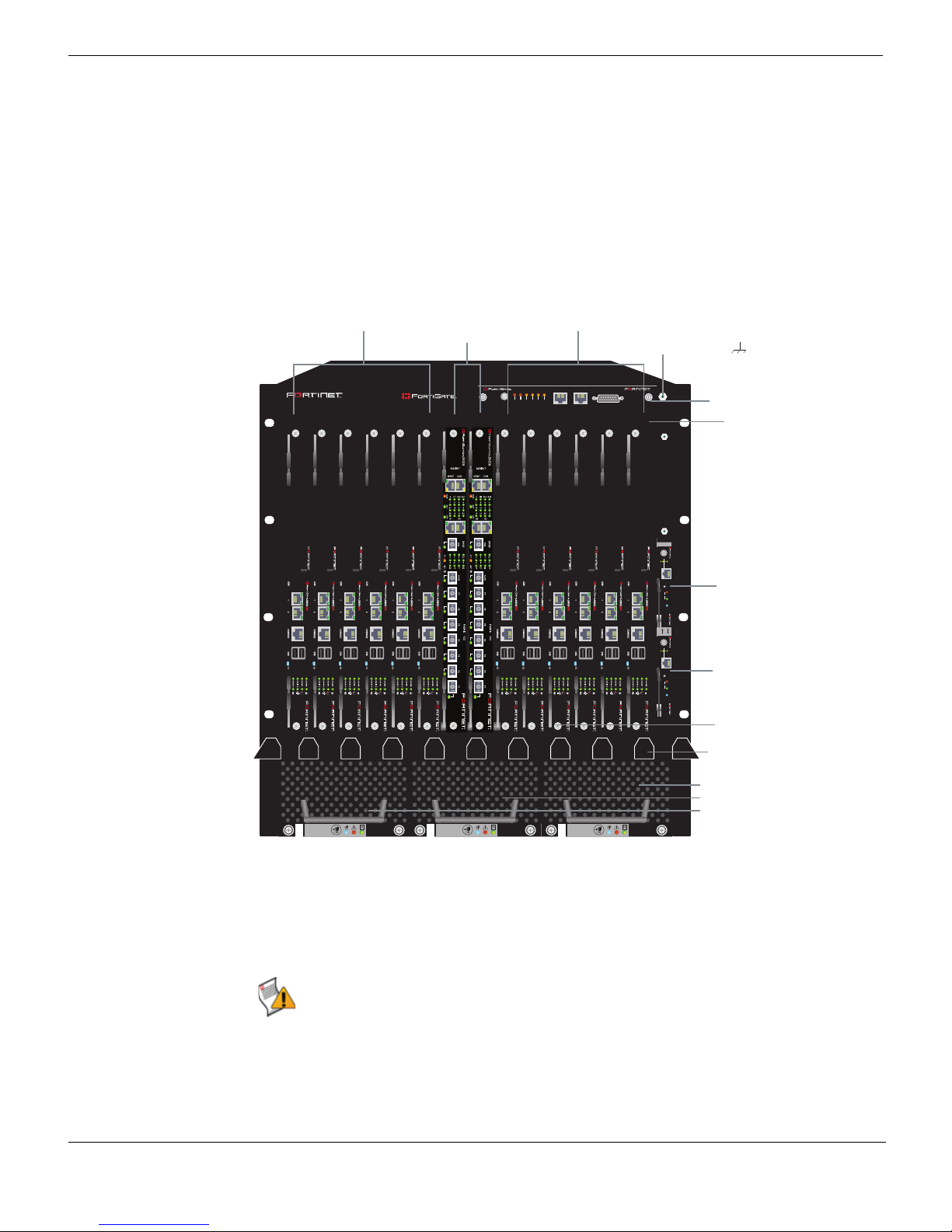
FortiGate-5001A-DW
boards
slots 4, 6, 8, 10,
12, and 14
Primary
shelf manager
Secondary
shelf manager
Cooling fan
trays 0, 1, 2
FortiGate-5001A-DW
boards
slots 3, 5, 7, 9,
11, and 13
FortiSwitch-5003A
boards
slots 1 and 2
Front cable
tray
ESD socket
Slot
numbers
Shelf alarm
panel (SAP)
Front accessible
air filter
FortiGate-5140 chassis front panel
Figure 1 shows the front panel of a FortiGate-5140 chassis. Two FortiSwitch-5003A
boards are installed in slots 1 and 2. Twelve FortiGate-5001A-DW boards installed in slots
3 to 14.
Figure 1: FortiGate-5140 chassis front panel with FortiGate-5001A-DW and FortiSwitch-5003A
boards installed
5140SAP
5140
1311975312468101214
CRITICAL
RESET
MAJOR
USER1
MINOR
SERIAL 1 SERIAL 2 ALARM
USER2
USER3
The FortiGate-5140 shelf alarm panel (SAP) and primary and secondary FortiGate-5140
Shelf Managers are also visible. The factory installed shelf alarm panel displays alarms,
provides a telco alarm interface, and also provides serial connections to the shelf
managers. The factory installed shelf managers provide power distribution, cooling,
alarms, and shelf status for the FortiGate-5140 chassis.
5000SM
ETH1
ETH0
10/100
10/100
link/Act
link/Act
ETH0
Service
RESET
STATUS
Hot Swap
12
5000SM
ETH1
ETH0
10/100
10/100
link/Act
link/Act
ETH0
FILTER
Service
RESET
STATUS
Hot Swap
0
Caution: Do not operate the FortiGate-5140 chassis with open slots on the front panel. For
optimum cooling performance and safety, the slots must contain a FortiGate-5000 series
FAN TRAY FAN TRAYFAN TRAY
12
board or an air baffle slot filler. As well the removable terminal block cover must be installed
over the power connectors on the back of the chassis.
16 01-30000-83466-20090108
FortiGate-5000 Series Introduction
http://docs.fortinet.com/ • Feedback
Page 17
FortiGate-5140-R chassis FortiGate-5140 chassis back panel
Also visible on the front of the FortiGate-5140 chassis:
• Electrostatic discharge (ESD) socket, used for connecting an ESD wrist or ankle band
when working with the chassis.
• Front cable tray, used for managing and securing ethernet and other cables.
• Front accessible air filter.
• Three hot swappable FortiGate-5140 cooling fan trays.
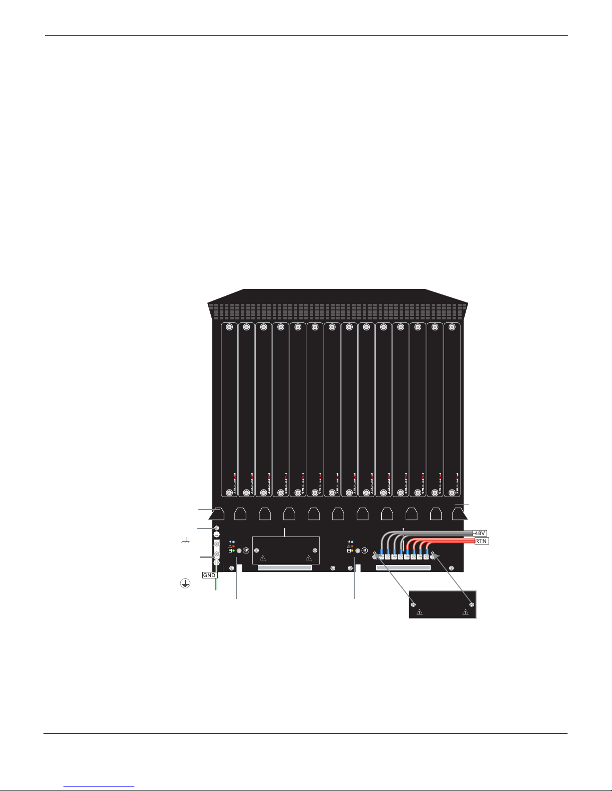
FortiGate-5140 chassis back panel
Figure 2 on page 17 shows the back panel of the FortiGate-5140 chassis. The back panel
includes two hot-swappable redundant -48V/-60 VDC power entry modules (PEMs)
labelled A and B. Fortinet ships the FortiGate-5140 chassis with PEM A and B installed.
The PEMs provide redundant DC power connections for the FortiGate-5140 chassis and
distribute DC power to the chassis slots and to the fan trays.
Figure 2: FortiGate-5140 chassis back panel
RTM
slot filler
panels
Back cable
tray
ESD
socket
Chassis
ground
connector
(green)
1412108642135791113
BPEM PEM
-48V/-60 VDC nom RETURN
B
PEM
-48V/-60 VDC
nom (black)
Power
Entry Module B
TERMINAL BLOCK COVER
Remove terminal block cover and
decable before removing PEM.
12341234
12341234
RTN
(red)
Entry Module A
-48V/-60 VDC nom RETURN
A
PEM
-48V/-60 VDC
nom (black)
Power
A
12341234
12341234
RTN
(red)
TERMINAL BLOCK COVER
Remove terminal block cover and
decable before removing PEM.
RTM
slot numbers
(terminal block
cover removed)
If you require redundant power you should connect both PEMs to DC power. If redundant
power is not required, you should connect PEM A to DC power. Each PEM has four
-48V/-60 VDC connectors and 4 RTN connections. All eight of these connectors should be
connected to DC power. Figure 2 on page 17 shows the terminal block cover removed
from PEM A and the wiring required to connect PEM A to DC power. While operating the
FortiGate-5140 both terminal block covers should be installed.
FortiGate-5000 Series Introduction
01-30000-83466-20090108 17
http://docs.fortinet.com/ • Feedback
Page 18

Physical description of the FortiGate-5140 chassis FortiGate-5140-R chassis
The power entry modules are hot swappable, which means you can remove and replace a
defective PEM while the FortiGate-5140 is operating assuming that the FortiGate-5140
system has both PEMs connected to DC power for redundancy.
The back panel also includes the back cable tray, an ESD socket and the chassis ground
connector. The ground connector must be connected to Data Center ground. Use the back
cable tray for securing and managing DC power, RTN, and ground wires.
Physical description of the FortiGate-5140 chassis
The FortiGate-5140 chassis is a 12U chassis that can be installed in a standard 19-inch
rack. Table 2 describes the physical characteristics of the FortiGate-5140 chassis.
Table 2: FortiGate-5140 chassis physical description
Dimensions 21 x 19 x 20.6 in. (53.3 x 48.3 x 52.4 cm)
(Height x Width x Depth)
Shipping weight
completely assembled
with packaging
Operating environment Temperature: 32 to 104°F (5 to 45°C)
Storage environment Temperature: -13 to 158°F (-25 to 70°C)
Power consumption Maximum: 2,980W DC
Power input 2x redundant -37VDC to -72VDC, 30A per power feed (total 4 + 4
110 lb. (50 kg)
Relative humidity: 5 to 85% (Non-condensing)
Relative humidity: 5 to 85% (Non-condensing)
power feeds)
18 01-30000-83466-20090108
FortiGate-5000 Series Introduction
http://docs.fortinet.com/ • Feedback
Page 19

FortiGate-5140 chassis FortiGate-5140 chassis front panel
FortiGate-5140 chassis
You can install up to 14 FortiGate-5000 series boards in the 14 front panel slots of the
FortiGate-5140 ATCA chassis. The FortiGate-5140 is a 12U chassis that contains two
redundant hot swappable DC power entry modules that connect to -48 VDC Data Center
DC power. The FortiGate-5140 chassis also includes three hot swappable cooling fan
trays. If all 14 front panel slots contain FortiGate-5005A2, FortiGate-5001SX, or
FortiGate-5001FA2 boards the FortiGate-5140 chassis provides a total of 112 1-Gigabit
ethernet FortiGate interfaces. If all 14 slots contain FortiGate-5001A boards the
FortiGate-5140 chassis supports 28 1-Gigabit ethernet FortiGate interfaces. If you add
FortiGate-ADM-XB2 modules to the FortiGate-5001A boards the FortiGate-5140 chassis
supports another 28 10-Gigabit interfaces.
You can also install a FortiSwitch-5003A or FortiSwitch-5003 board in the FortiGate-5140
chassis to provide base backplane communications. Base backplane communications can
be used for HA heartbeat communications and for data communications. You can add a
second FortiSwitch-5003A or FortiSwitch-5003 board for redundancy. FortiSwitch-5003A
boards can also provide fabric backplane communication using the FortiGate-5140 fabric
backplane channels.
You can mix and match any combination of FortiGate-5000 series boards in the
FortiGate-5140 chassis. For example, you could install four FortiGate-5005FA2 boards,
four FortiGate-5001SX boards, and four FortiGate-5001FA2 boards. You can also install
FortiController-5208 and FortiGate-5005FA2 boards in a FortiGate-5140 chassis to create
a FortiGate-5005-DIST security system.
Some of the boards installed in a FortiGate-5140 chassis can be operating in a FortiGate
HA cluster and some can be operating as standalone FortiGate units. You can also
operate multiple HA clusters and standalone FortiGate units in a single FortiGate-5140
chassis. You can also use FortiSwitch-5003A or FortiSwitch-5003 boards to operate HA
clusters consisting of FortiGate-5000 series boards installed in multiple FortiGate-5000
chassis. You can also use FortiSwitch-5003A boards for fabric data communication
between chassis.
The FortiGate-5140 chassis requires -48VDC Data Center DC power. If DC power is not
available you can install a FortiGate-5053 power converter tray (purchased separately)
with FortiGate-5140 power supplies.
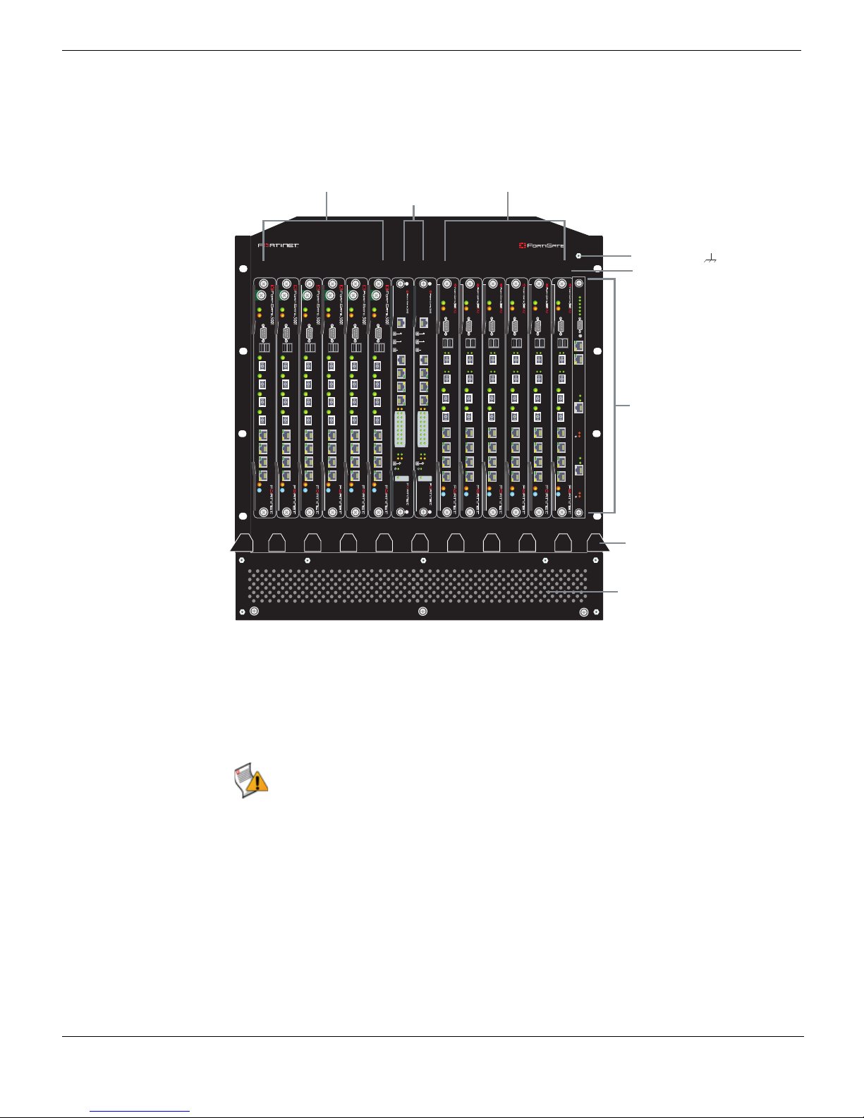
FortiGate-5140 chassis front panel
Figure 3 shows the front panel of a FortiGate-5140 chassis. Two FortiSwitch-5003 boards
are installed in slots 1 and 2. Six FortiGate-5001SX boards are installed in slots 3, 5, 7, 9,
11, and 13 and six FortiGate-5001FA2 boards are installed in slots 4, 6, 8, 10, 12, and 14.
The primary and secondary FortiGate-5140 Shelf Managers are also visible. The factory
installed shelf managers provide power distribution, cooling, alarms, shelf status, and a
telco alarm interface for the FortiGate-5140 chassis.
FortiGate-5000 Series Introduction
01-30000-83466-20090108 19
http://docs.fortinet.com/ • Feedback
Page 20
FortiGate-5140 chassis back panel FortiGate-5140 chassis
Figure 3: FortiGate-5140 chassis front panel with FortiGate-5001SX, FortiGate-5001FA2, and
FortiSwitch-5003 boards installed
FortiGate-5001SX
boards
slots 3, 5, 7, 9,
11, and 13
FortiSwitch-5003
boards
FortiGate-5001FA2
boards
slots 4, 6, 8, 10,
12, and 14
slots 1 and 2
13 11 9 7 5 3 1 2 4 6 8 10 12 14
PWR
PWR
PWR
PWR
PWR
PWR
PWR
PWR
PWR
ACC
ACC
ACC
ACC
CONSOLE
CONSOLE
CONSOLE
USB
USB
USB
1 2 3 4 5 6 7 8
1 2 3 4 5 6 7 8
1 2 3 4 5 6 7 8
STA IPM
STA IPM
STA IPM
STA IPM
PWR
ACC
ACC
CONSOLE
USB
1 2 3 4 5 6 7 8
MANAGEMENT
CONSOLE
CONSOLE
USB
USB
SYSTEM
CONSOLE
1 2 3 4 5 6 7 8
1 2 3 4 5 6 7 8
E1
E2
1514
1312
1110
98
76
54
32
10
ZRE
OKCLK
INTEXT
FLT
FLT
HOT SWAP
RESET
LED MODE
STA IPM
STA IPM
ACC
ACC
MANAGEMENT
E
T
H
O
R
S
2
3
2
Z
R
E
0
Z
R
E
1
Z
R
E
2
CONSOLE
E
T
H
O
SYSTEM
CONSOLE
R
S
2
3
2
Z
R
E
0
Z
R
E
1
Z
R
E
2
E1
E2
1514
1312
1110
98
76
54
32
10
ZRE
OKCLK
INTEXT
FLT
FLT
HOT SWAP
RESET
LED MODE
STA IPM
ACC
CONSOLE
USB
USB
1 2
1 2
3 4
3 4
5 6 7 8
5 6 7 8
STA IPM
STA IPM
PWR
ACC
ACC
CONSOLE
CONSOLE
CONSOLE
USB
USB
USB
1 2
1 2
1 2
3 4
3 4
3 4
5 6 7 8
5 6 7 8
5 6 7 8
STA IPM
STA IPM
5140
ESD socket
Slot
Crit.
PWR
Maj.
Min.
ACC
3
2
1
CONSOLE
Alarms
Rst
USB
1 2
Serial 1
Serial 2
Link
Act
3 4
100
ETH 0
Prim.
ShMC
5 6 7 8
Stat.
Link
Act
100
ETH 0
Sec.
STA IPM
ShMC
Stat.
numbers
FortiGate-5140
Shelf Manager
Front cable
tray
Also visible on the front of the FortiGate-5140:
• Electrostatic discharge (ESD) socket, used for connecting an ESD wrist or ankle band
when working with the chassis.
• Front cable tray, used for managing and securing ethernet and other cables.
• Three hot swappable FortiGate-5140 cooling fan trays.
Caution: Do not operate the FortiGate-5140 chassis with open slots on the front panel. For
optimum cooling performance and safety, the slots must contain a FortiGate-5000 series
board or an air baffle slot filler. As well the removable terminal block cover must be installed
over the power connectors on the back of the chassis.
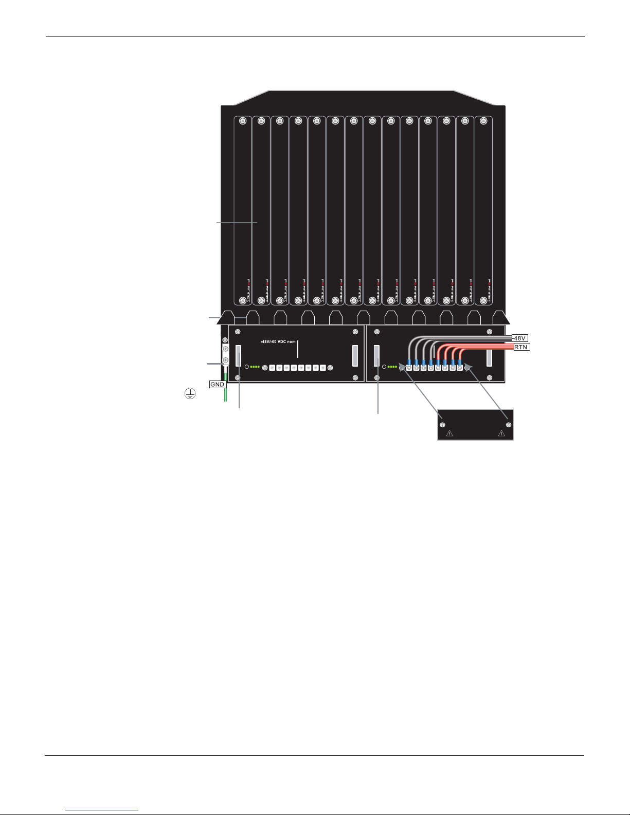
FortiGate-5140 chassis back panel
Figure 4 shows the back panel of the FortiGate-5140 chassis. The back panel includes
two hot-swappable redundant -48V/-60 VDC power entry modules (PEMs) labelled PEM A
and PEM B. Fortinet ships the FortiGate-5140 chassis with PEM A and PEM B installed.
The PEMs provide redundant DC power connections for the FortiGate-5140 chassis and
distribute DC power to the fan trays and to the FortiGate-5000 series boards installed in
the FortiGate-5140 chassis.
3 hot-swappable
cooling fan trays
(numbered 0, 1, and
2 behind panel)
20 01-30000-83466-20090108
FortiGate-5000 Series Introduction
http://docs.fortinet.com/ • Feedback
Page 21
FortiGate-5140 chassis FortiGate-5140 chassis back panel
Figure 4: FortiGate-5140 chassis back panel
RTM
slot filler
panels
Back cable
tray
B PEM
PEM
RTN
1 2 3 4 1 2 3 4
-48V/-60 VDC nom RTN
A
1 2 3 4 1 2 3 4
Chassis
ground
connector
(green)
Entry Module B
(terminal block
HS
HS
Alarm
operate
-48V/-60 VDC
nom (black)
Power
1 2 3 4 1 2 3 4
RTN
(red)
HS
HS
Alarm
operate
-48V/-60 VDC
nom (black)
Power
Entry Module A
1 2 3 4 1 2 3 4
RTN
(red)
TERMINAL BLOCK COVER
Remove terminal block cover and
decable before removing PEM.
cover removed)
If you require redundant power you should connect both PEMs to DC power. If redundant
power is not required, you should connect PEM A to DC power. Each PEM has four
-48V/-60 VDC connectors and 4 RTN connections. All eight of these connectors should be
connected to DC power. Figure 4 on page 21 shows the terminal block cover removed
from PEM A and the wiring required to connect PEM A to DC power. While operating the
FortiGate-5140 both terminal block covers should be installed.
The power entry modules are hot swappable, which means you can remove and replace a
defective PEM while the FortiGate-5140 is operating assuming that the FortiGate-5140
system has both PEMs connected to DC power for redundancy.
The back panel also includes the back cable tray, an ESD socket and the chassis ground
connector. The ground connector must be connected to Data Center ground. Use the back
cable tray for securing and managing DC power, RTN, and ground wires.
FortiGate-5000 Series Introduction
01-30000-83466-20090108 21
http://docs.fortinet.com/ • Feedback
Page 22

Physical description of the FortiGate-5140 chassis FortiGate-5140 chassis
Physical description of the FortiGate-5140 chassis
The FortiGate-5140 chassis is a 12U chassis that can be installed in a standard 19-inch
rack. Table 3 describes the physical characteristics of the FortiGate-5140 chassis.
Table 3: FortiGate-5140 chassis physical description
Dimensions 21 x 19 x 16.8 in. (53.3 x 48.3 x 42.7 cm)
(H x W x D)
Shipping weight
completely assembled
with packaging
Operating environment Temperature: 32 to 104°F (0 to 40°C)
Storage environment Temperature: -13 to 158 °F (-25 to 70°C)
Power consumption Maximum: 2,980W DC
Power input 2x redundant -48VDC to -58VDC
110 lb. (50 kg)
Relative humidity: 5 to 95% (Non-condensing)
Relative humidity: 5 to 95% (Non-condensing)
22 01-30000-83466-20090108
FortiGate-5000 Series Introduction
http://docs.fortinet.com/ • Feedback
Page 23

FortiGate-5050-R chassis
FortiGate-5050-R chassis
You can install up to five FortiGate-5000 series boards in the five slots of the
FortiGate-5050 ATCA chassis. The FortiGate-5050 is a 5U 19-inch rackmount ATCA
chassis that contains two redundant DC power connections that connect to -48 VDC Data
Center DC power. The FortiGate-5050 chassis also includes a hot swappable cooling fan
tray. If all five slots contain FortiGate-5005FA2, FortiGate-5001SX, or FortiGate-5001FA2
boards, the FortiGate-5050 chassis provides a total of 40 FortiGate gigabit ethernet
interfaces. If all 5 slots contain FortiGate-5001A boards the FortiGate-5050 chassis
supports ten 1-Gigabit ethernet FortiGate interfaces. If you add FortiGate-ADM-XB2
modules to the FortiGate-5001A boards the FortiGate-5050 chassis supports another ten
10-Gigabit interfaces.
You can also install a FortiSwitch-5003A or FortiSwitch-5003 board in the FortiGate-5050
chassis to provide base backplane communications. Base backplane communications can
be used for HA heartbeat communications and for data communications. You can add a
second FortiSwitch-5003A or FortiSwitch-5003 board for redundancy. FortiSwitch-5003A
boards can also provide fabric backplane communication using the FortiGate-5050 fabric
backplane channels.
You can mix and match any combination of FortiGate-5000 series boards in the
FortiGate-5050 chassis. For example, you could install two FortiGate-5005FA2 boards,
two FortiGate-5001SX boards, and one FortiGate-5001FA2 board. You can also install
FortiController-5208 and FortiGate-5005FA2 boards in a FortiGate-5050 chassis to create
a FortiGate-5005-DIST security system.
Some of the boards installed in a FortiGate-5050 chassis can be operating in a FortiGate
HA cluster and some can be operating as standalone FortiGate units. You can also
operate multiple HA clusters and standalone FortiGate units in a single FortiGate-5050
chassis. You can also use FortiSwitch-5003A or FortiSwitch-5003 boards to operate HA
clusters consisting of FortiGate-5000 series boards installed in multiple FortiGate-5000
chassis. You can also use FortiSwitch-5003A boards for fabric data communication
between chassis.
The FortiGate-5050 chassis requires -48VDC Data Center DC power. If DC power is not
available you can install a FortiGate-5053 power converter tray (purchased separately)
with FortiGate-5020/5050 power supplies.
FortiGate-5000 Series Introduction
01-30000-83466-20090108 23
http://docs.fortinet.com/ • Feedback
Page 24
FortiGate-5050 front panel FortiGate-5050-R chassis
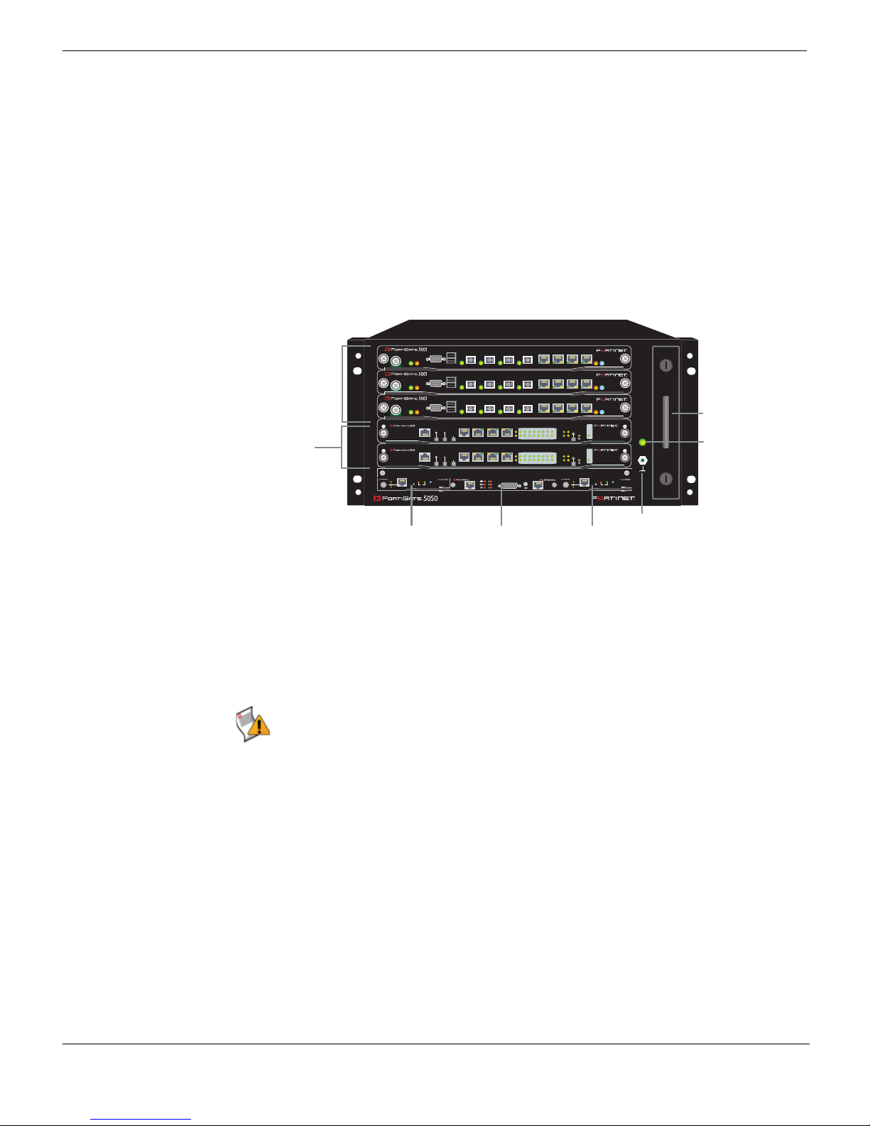
FortiGate-5050 front panel
Figure 5 shows the front of a FortiGate-5050 chassis. Two FortiSwitch-5003 boards are
installed in slots 1 and 2. Three FortiGate-5001SX boards are installed in slots 3, 4, and 5.
The FortiGate-5050 primary and secondary Shelf Managers and the Shelf Alarm Panel
(SAP) are also visible. The factory installed shelf alarm panel displays alarms, provides a
telco alarm interface, and also provides serial connections to the shelf managers. The
factory installed shelf managers provide power distribution, cooling, alarms, and shelf
status for the FortiGate-5050 chassis.
Figure 5: FortiGate-5050 front panel with FortiGate-5001SX and FortiSwitch-5003 boards
installed
USB
1 2 3 4 5 6 7 8
FortiGate-5001SX
boards
slots 3, 4,
and 5
FortiSwitch-5003
boards
slots 1 and 2
5
4
3
2
1
SMC
2
CONSOLE
ACC
PWR
USB
1 2 3 4 5 6 7 8
CONSOLE
ACC
PWR
USB
1 2 3 4 5 6 7 8
CONSOLE
ACC
PWR
ETH
O
RS232ZRE0ZRE1ZRE2
SYSTEM
CONSOLE
MANAGEMENT
ETH
O
RS232ZRE0ZRE1ZRE2
SYSTEM
CONSOLE
MANAGEMENT
5000SM
10/100
ETH0
Service
link/Act
ETH1
STATUS
10/100
RESET
ETH0
link/Act
5050SAP
SERIAL
Hot Swap
1
E1
9876543210
1514
1312
1110
E2
E1
9876543210
1514
1312
1110
E2
SERIAL
ALARM
2
STA IPM
STA IPM
STA IPM
OKCLK
INTEXT
FLT
HOT SWAP
RESET
ZRE
LED MODE
FLT
OKCLK
INTEXT
FLT
HOT SWAP
RESET
ZRE
LED MODE
FLT
5000SM
10/100
ETH0
Service
link/Act
ETH1
10/100
ETH0
link/Act
POWER
SMC
STATUS
Hot Swap
RESET
1
Hot-swappable
cooling fan tray
Power LED
Secondary
Shelf Manager
(SMC 2)
Shelf Alarm
Panel (SAP)
Primary
Shelf Manager
(SMC 1)
Also visible on the front of the FortiGate-5050:
• The location of the hot swappable FortiGate-5050 cooling fan tray behind panel.
• Power LED.
• ESD socket, used for connecting an ESD wrist or ankle band when working with the
chassis.
Caution: Do not operate the FortiGate-5050 chassis with open slots on the front panel. For
optimum cooling performance and safety, the slots must contain a FortiGate-5000 series
board or an air baffle slot filler. As well the removable power supply panel must be installed
over the power connectors on the back of the chassis.
ESD socket
24 01-30000-83466-20090108
FortiGate-5000 Series Introduction
http://docs.fortinet.com/ • Feedback
Page 25

FortiGate-5050-R chassis FortiGate-5050 back panel
FortiGate-5050 back panel
Figure 6 shows the back of a FortiGate-5050 chassis. The FortiGate-5050 chassis back
panel includes two redundant -48V to - 58V DC power input connectors labelled Input A
and Input B. The power input connectors provide redundant DC power connections for the
FortiGate-5050 chassis and distribute DC power to the fan tray and the FortiGate-5000
series boards installed in the FortiGate-5050 chassis. Each power input connector
includes a 24 Amp circuit breaker that also functions as an on/off switch for the power
input connector.
If you require redundant power you should connect both power input connectors to DC
power. If redundant power is not required, you should connect power input connector A to
DC power. When operating, the power input connectors are covered with clear protection
plates.
Figure 6: FortiGate-5050 chassis back panel
5
4
3
RTM
slot filler
panels
2
1
Ground
Connector
-48V
RTN (-DC IN)
INPUT A
24
AMP
-48V
RTN (-DC IN)
INPUT B
24
AMP
(green)
Power
wire
fixture
Positive
(RTN)
(red)
DC Power
Input A
-48V
(-DC in)
(black)
Positive
(RTN)
(red)
DC Power
-48V
(-DC in)
(black)
ESD socket
Input B
The back panel includes the FortiGate-5050 chassis ground connector which must be
connected to Data Center ground. Use the power wire fixtures for securing and managing
DC power wires. The FortiGate-5050 chassis also includes an ESD socket on the back
panel.
FortiGate-5000 Series Introduction
01-30000-83466-20090108 25
http://docs.fortinet.com/ • Feedback
Page 26

Physical description of the FortiGate-5050 chassis FortiGate-5050-R chassis
Physical description of the FortiGate-5050 chassis
The FortiGate-5050 chassis is a 5U chassis that can be installed in a standard 19-inch
rack. Table 4 describes the physical characteristics of the FortiGate-5050 chassis.
Table 4: FortiGate-5050 chassis physical description
Dimensions 8.75 x 17 x 15.5 in. (13.3 x 43.2 x 39.4 cm)
(H x W x D)
Shipping weight
completely assembled
with packaging
Operating environment Temperature: 32 to 104°F (0 to 45°C)
Storage environment Temperature: -13 to 158 °F (-25 to 70°C)
Power consumption Maximum: 1,135 W
Power input 2x redundant -48VDC to -58VDC
26.75 lb. (12.1 kg)
Relative humidity: 5 to 85% (Non-condensing)
Relative humidity: 5 to 95% (Non-condensing)
26 01-30000-83466-20090108
FortiGate-5000 Series Introduction
http://docs.fortinet.com/ • Feedback
Page 27

FortiGate-5050 chassis
FortiGate-5050 chassis
You can install up to five FortiGate-5000 series boards in the five slots of the
FortiGate-5050 ATCA chassis. The FortiGate-5050 is a 5U 19-inch rackmount ATCA
chassis that contains two redundant DC power connections that connect to -48 VDC Data
Center DC power. The FortiGate-5050 chassis also includes a hot swappable cooling fan
tray. If all five slots contain FortiGate-5005FA2, FortiGate-5001SX, or FortiGate-5001FA2
boards, the FortiGate-5050 chassis provides a total of 40 1-Gigabit ethernet FortiGate
interfaces. If all 5 slots contain FortiGate-5001A boards the FortiGate-5050 chassis
supports 10 1-Gigabit ethernet FortiGate interfaces. If you add FortiGate-ADM-XB2
modules to the FortiGate-5001A boards the FortiGate-5050 chassis supports up to ten
10-Gigabit interfaces
You can also install FortiSwitch-5003A or FortiSwitch-5003 boards in the FortiGate-5050
chassis slots 1 and 2 to provide base backplane communications. Base backplane
communications can be used for HA heartbeat communications and data communications
using FortiGate-5050 base backplane channels. You can add a second FortiSwitch-5003A
or FortiSwitch-5003 board for redundancy. FortiSwitch-5003A boards can also provide
fabric backplane communication using the FortiGate-5050 fabric backplane channels.
You can mix and match any combination of FortiGate-5000 series boards in the
FortiGate-5050 chassis. For example, you could install two FortiGate-5005FA2 boards,
two FortiGate-5001SX boards, and one FortiGate-5001FA2 board. You can also install
FortiController-5208 and FortiGate-5005FA2 boards in a FortiGate-5050 chassis to create
a FortiGate-5005-DIST security system.
Some of the boards installed in a FortiGate-5050 chassis can be operating in a FortiGate
HA cluster and some can be operating as standalone FortiGate units. You can also
operate multiple HA clusters and standalone FortiGate units in a single FortiGate-5050
chassis. You can also use FortiSwitch-5003A or FortiSwitch-5003 boards to operate HA
clusters consisting of FortiGate-5000 series boards installed in multiple FortiGate-5000
chassis. You can also use FortiSwitch-5003A boards for fabric data communication
between chassis.
The FortiGate-5050 chassis requires -48VDC Data Center DC power. If DC power is not
available you can install a FortiGate-5053 power converter tray (purchased separately)
with FortiGate-5020/5050 power supplies.
FortiGate-5000 Series Introduction
01-30000-83466-20090108 27
http://docs.fortinet.com/ • Feedback
Page 28

FortiGate-5050 front panel FortiGate-5050 chassis
FortiGate-5050 front panel
Figure 7 shows the front of a FortiGate-5050 chassis. Two FortiSwitch-5003 boards are
installed in slots 1 and 2. Three FortiGate-5001SX boards are installed in slots 3, 4, and 5.
The FortiGate-5050 primary Shelf Manager is also visible. The factory-installed shelf
managers provide power distribution, cooling, alarms, shelf status, and a telco alarm
interface for the FortiGate-5050 chassis.
Figure 7: FortiGate-5050 front panel with FortiGate-5001SX and FortiSwitch-5003 boards
installed
USB
1 2 3 4 5 6 7 8
FortiGate-5001SX
boards
slots 3, 4,
and 5
FortiSwitch-5003
boards
slots 1 and 2
5
4
3
2
1
ShMC
2
USB
1 2 3 4 5 6 7 8
CONSOLE
ACC
PWR
USB
1 2 3 4 5 6 7 8
CONSOLE
ACC
PWR
ETH
O
MANAGEMENT
MANAGEMENT
ETH
O
RS232ZRE0ZRE1ZRE2
SYSTEM
CONSOLE
RS232ZRE0ZRE1ZRE2
SYSTEM
CONSOLE
E1
9876543210
1514
1312
1110
E2
E1
9876543210
1514
1312
1110
E2
CONSOLE
ACC
PWR
STA IPM
STA IPM
STA IPM
OKCLK
INTEXT
FLT
HOT SWAP
RESET
ZRE
FLT
OKCLK
INTEXT
FLT
HOT SWAP
RESET
ZRE
FLT
Critical
Major
Minor
Alarm
Alarm
Console Ethernet
Reset
POWER
LED MODE
LED MODE
ShMC
Hot Swap
Status
1
Hot-swappable
cooling fan tray
Power LED
Also visible on the front of the FortiGate-5050:
• Electrostatic discharge (ESD) socket, used for connecting an ESD wrist or ankle band
when working with the chassis.
• The location of the hot swappable FortiGate-5050 cooling fan tray behind panel.
• Power LED.
Caution: Do not operate the FortiGate-5050 chassis with open slots on the front panel. For
optimum cooling performance and safety, the slots must contain a FortiGate-5000 series
board or an air baffle slot filler. As well the removable power supply panel must be installed
over the power connectors on the back of the chassis.
FortiGate-5050 back panel
Figure 8 shows the back panel of a FortiGate-5050 chassis. The back panel includes two
redundant -48V to - 58V DC power input connectors labelled Input A and Input B. The
power input connectors provide redundant DC power connections for the FortiGate-5050
chassis and distribute DC power to the fan tray and the FortiGate-5000 series boards
installed in the FortiGate-5050 chassis. Each power input connector includes a 24 Amp
circuit breaker that also functions as an on/off switch for the power input connector.
If you require redundant power you should connect both power input connectors to DC
power. If redundant power is not required, you should connect power input connector A to
DC power. When operating, the power input connectors are covered with clear protection
plates.
FortiGate-5050
Shelf Manager
ESD socket
28 01-30000-83466-20090108
FortiGate-5000 Series Introduction
http://docs.fortinet.com/ • Feedback
Page 29

FortiGate-5050 chassis Physical description of the FortiGate-5050 chassis
5
4
3
2
1
-48V to -58V
(-DC in)
(black)
Power
wire
Ground
(green)
-48V to -58V
(-DC in)
(black)
Positive
(RTN)
(red)
Positive
(RTN)
(red)
DC VOLTAGE RANGE
-48V TO -58V
RTN (-DC IN)
INPUT B
25
AMP
DC VOLTAGE RANGE
-48V TO -58V
RTN (-DC IN)
INPUT A
25
AMP
RTN
GND
RTN
-48V
-48V
RTM
slot filler
panels
Figure 8: FortiGate-5050 chassis back panel
The back panel includes the FortiGate-5050 chassis ground connector which must be
connected to Data Center ground. Use the power wire fixtures for securing and managing
DC power wires. The FortiGate-5050 chassis also includes an ESD socket on the back
panel.
The back panel also contains 5 RTM slots numbered to correspond to the front panel
slots. The RTM slots are available for FortiGate-5000 RTM modules such as the
FortiGate-RTM-XB2 module. When the FortiGate-5050 chassis is shipped, these slots are
covered by RTM slot filler panels.
Physical description of the FortiGate-5050 chassis
The FortiGate-5050 chassis is a 5U chassis that can be installed in a standard 19-inch
rack. Table 5 describes the physical characteristics of the FortiGate-5050 chassis.
Table 5: FortiGate-5050 chassis physical description
Dimensions 8.75 x 17 x 15.5 in. (13.3 x 43.2 x 39.4 cm)
Weight 26.75 lb. (12.1 kg)
Operating environment Temperature: 32 to 104°F (0 to 45°C)
Storage environment Temperature: -13 to 158 °F (-25 to 70°C)
Power consumption Maximum: 1,135 W
Power input 2x redundant -48VDC to -58VDC
FortiGate-5000 Series Introduction
01-30000-83466-20090108 29
http://docs.fortinet.com/ • Feedback
(H x W x D)
Relative humidity: 5 to 85% (Non-condensing)
Relative humidity: 5 to 95% (Non-condensing)
Page 30

Physical description of the FortiGate-5050 chassis FortiGate-5050 chassis
30 01-30000-83466-20090108
FortiGate-5000 Series Introduction
http://docs.fortinet.com/ • Feedback
Page 31

FortiGate-5020 chassis FortiGate-5020 front panel
Hot-swappable FortiGate-5020/5050
power supplies (behind panel)
Power LEDs
PSU A
PSU B
FortiGate-5001SX
board
FortiGate-5005FA2
board
Hot swappable cooling fan tray
(accessable from back panel)
FortiGate-5020 chassis
You can install one or two FortiGate-5000 series boards in the two slots of the
FortiGate-5020 ATCA chassis. The FortiGate-5020 is a 4U chassis that contains
two redundant AC to DC power supplies that connect to AC power. The
FortiGate-5020 chassis also includes an internal cooling fan tray. If both slots
contain FortiGate-5000 boards, the FortiGate-5020 chassis provides up to 16
FortiGate gigabit ethernet interfaces.
If you install the same FortiGate-5000 series board in both slots, you can
configure the boards to operate as an HA cluster. HA heartbeat communications
between the boards uses the FortiGate-5020 base backplane communication
channel. No extra switching or other connections are required.
You can also use the base backplane channels for data communication between
the FortiGate-5000 series boards installed in the FortiGate-5020 chassis. You can
configure base backplane communication between two identical FortiGate-5000
series boards (for example between two FortiGate-5001SX boards) or between
different FortiGate-5000 series boards (for example, between a FortiGate-5001SX
and a FortiGate-5005FA2 board) as long as both boards use the same base
backplane channel.
The FortiGate-5020 chassis can only be connected to AC power. Two redundant
FortiGate-5020/5050 power supplies are factory installed in the FortiGate-5020
chassis.
FortiGate-5020 front panel
Figure 9 shows the front of a FortiGate-5020 chassis. A FortiGate-5001SX board
and a FortiGate-5005FA2 board are installed. The FortiGate-5020/5050 power
supplies are factory installed behind the panel at the top of the chassis. The power
LEDs for the power supplies are visible on the front panel as well.
Figure 9: FortiGate-5020 front panel with two FortiGate series boards
PSU A
PSU B
USB
CONSOLE
ACC
PWR
ACT
LINK
BASE
ACT
FABRIC
LINK
CONSOLE
1 2 3 4 5 6 7 8
USB USB
OOS ACC STATUS
3 412 56
STA IPM
78
IPM
FortiGate-5000 Series Introduction
01-30000-83466-20090108 31
Page 32

FortiGate-5020 back panel FortiGate-5020 chassis
FortiGate-5020 back panel
Figure 10 shows the back of a FortiGate-5020 chassis. The chassis back panel
includes two redundant AC power connectors and provides access to the hot
swappable cooling fan tray. Each AC power connector includes a 25 Amp circuit
breaker that also functions as the on/off switch for the AC power connector. You
can use the power wire fixtures to secure AC power wires to prevent the power
wires from being accidently disconnected.
Figure 10: FortiGate-5020 chassis back panel
Circuit
breaker
AC power
connector
Hot swappable
cooling fan tray
AC power
connector
Power
wire
fixture
Circuit
breaker
Power
wire
fixture
Physical description of the FortiGate-5020 chassis
The FortiGate-5020 chassis is a 4U chassis that can be installed in a standard
19-inch rack. Ta bl e 6 describes the physical characteristics of the FortiGate-5020
chassis.
Table 6: FortiGate-5020 physical description
Dimensions 5.25 x 17 x 15.5 in. (13.3 x 43.2 x 39.4 cm)
(H x W x D)
Weight 35.5 lb. (16.1 kg)
Operating environment Temperature: -13 to 158 °F (-25 to 70°C)
Relative humidity: 5 to 95% (Non-condensing)
Storage environment Temperature: -20 to 80°C
Relative humidity: 5 to 95% (Non-condensing)
Power dissipation Maximum: 800 watts
Power input 2x redundant 110 to 250 VAC
FortiGate-5000 Series Introduction
32 01-30000-83466-20090108
Page 33

FortiGate-5001A security system
FortiGate-5001A security system
The FortiGate-5001A security system is a high-performance Advanced
Telecommunications Computing Architecture (ACTA) compliant FortiGate security
system that can be installed in any ACTA chassis including the FortiGate-5140,
FortiGate-5050, or FortiGate-5020 chassis.
Two FortiGate-5001A models are available:
• The FortiGate-5001A-DW (double-width) board includes a double-width
Advanced Mezzanine Card (AMC) opening. You can install a supported
FortiGate AMC Double width Module (ADM) such as the FortiGate-ADM-XB2
or the FortiGate-ADM-FB8 in the AMC opening. The FortiGate-ADM-XB2 adds
two accelerated 10-gigabit interfaces to the FortiGate-5001A board and the
FortiGate-ADM-FB8 adds 8 accelerated 1-gigabit interfaces.
• The FortiGate-5001A-SW (single-width) includes a single-width AMC opening.
You can install a supported FortiGate AMC Single width Module (ASM) such
as the FortiGate-ASM-FB4 or the FortiGate-ASM-S08 in the AMC opening.
The FortiGate-ASM-FB4 adds four accelerated 1-gigabit interfaces to the
FortiGate-5001A board and the FortiGate-ADM-S08 adds a removable hard
disk that you can use to store log files and content archives.
Other than the double-width and single-width AMC openings, the
FortiGate-5001A-DW and SW models have the same functionality and
performance.
The FortiGate-5001A security system contains two front panel 1-gigabit ethernet
interfaces, two base backplane 1-gigabit interfaces, and two fabric backplane
1-gigabit interfaces. Use the front panel interfaces for connections to your
networks and the backplane interfaces for communication across the ACTA
chassis backplane.
If you install a FortiGate-RTM-XB2 module for each FortiGate-5001A board, the
FortiGate-5001A fabric interfaces can operate at 10 Gbps. The
FortiGate-RTM-XB2 also provides NP2-accelerated network processing for
eligible traffic passing through the FortiGate-RTM-XB2 interfaces.
You can also configure two or more FortiGate-5001A boards to create a high
availability (HA) cluster using the base or fabric backplane interfaces for HA
heartbeat communication through the chassis backplane, leaving front panel
interfaces available for network connections.
Note: In most cases the base backplane interfaces are used for HA heartbeat
communication and the fabric backplane interfaces are used for data communication.
The FortiGate-5001A board also supports high-end FortiGate features including
802.1Q VLANs, multiple virtual domains, 802.3ad aggregate interfaces, and
FortiOS Carrier.
FortiGate-5000 Series Introduction
01-30000-83466-20090108 33
Page 34

Front panel LEDs and connectors FortiGate-5001A security system
Fabri
RJ-4
Fabri
RJ-4
Figure 11: FortiGate-5001A-DW front panel
Double-width AMC
opening
5
Console
c and Base
network activity
LEDs
USB
Retention
Screw
Extraction
Lever
port1 and port2
10/100/1000
Copper Interfaces
IPM
LED
(board
position)
ACC
OOS
Power
Status
LEDs
Retention
Extraction
Lever
Figure 12: FortiGate-5001A-SW front panel
c and Base
network activity
LEDs
USB
IPM
LED
(board
position)
ACC
OOS
Power
Status
LEDs
Retention
Extraction
Lever
Retention
Screw
Extraction
Lever
5001A-SW
Single-width AMC
opening
Console
port1 and port2
10/100/1000
Copper Interfaces
5
The FortiGate-5001A board includes the following features:
• Two front panel 10/100/1000Base-T copper 1-gigabit ethernet interfaces.
• Two base backplane 1-gigabit interfaces (base CH0 and Base CH1 on the
front panel and base1 and base2 in the firmware) for HA heartbeat and data
communications across the FortiGate-5000 chassis backplane.
• Two fabric backplane interfaces (Fabric CH0 and Fabric CH1 on the front
panel and fabric1 and fabric2 in the firmware) for HA heartbeat and data
communications across the FortiGate-5000 chassis backplane. The fabric
backplane interfaces operate at 1 Gbps. If you install a FortiGate-RTM-XB2
module the fabric backplane interfaces operate at 10 Gbps.
• One double-width AMC opening (FortiGate-5001A-DW board).
• One single-width AMC opening (FortiGate-5001A-SW board).
• RJ-45 RS-232 serial console connection.
• 2 USB connectors.
• Mounting hardware.
• LED status indicators.
Screw
Screw
Front panel LEDs and connectors
From the FortiGate-5001A font panel you can view the status of the front panel
LEDs to verify that the board is functioning normally. You also connect the
FortiGate-5001A board to your network through the front panel 10/100/1000
ethernet connectors. The front panel also includes the RJ-45 console port for
connecting to the FortiOS CLI and two USB ports. The USB ports can be used
with any USB key for backing up and restoring configuration files. For information
about using the using a USB key with a FortiGate unit, see the FortiGate-5000
Series Firmware and FortiUSB Guide.
34 01-30000-83466-20090108
FortiGate-5000 Series Introduction
Page 35

FortiGate-5001A security system Front panel LEDs and connectors
LEDs
Ta bl e 7 lists and describes the FortiGate-5001A LEDs.
Table 7: FortiGate-5001A LEDs
LED State Description
1, 2
(Left LED)
1, 2
(Right LED)
Base CH0 Green Base backplane interface 0 (base1) is connected at 1 Gbps.
Base CH1 Green Base backplane interface 1 (base2) is connected at 1 Gbps.
Fabric CH0 Off Fabric backplane interface 0 (fabric1) is connected at 10
Fabric CH1 Off Fabric backplane interface 1 (fabric2) is connected at 10
ACC
OOS
(Out of
Service)
Power
Green The correct cable is connected to the interface and the
Flashing
Green
Off No link is established.
Green Connection at 1 Gbps.
Amber Connection at 100 Mbps.
Off Connection at 10 Mbps.
Flashing
Green
Flashing
Green
Flashing
Green
Flashing
Green
Off or
Flashing
green
Off Normal operation.
Green A fault condition exists and the FortiGate-5001A blade is out
Green The FortiGate-5001A board is powered on.
connected equipment has power.
Network activity at the interface.
Network activity at base backplane interface 0.
Network activity at base backplane interface 1.
Gbps.
Network activity at fabric backplane interface 0.
Gbps.
Network activity at fabric backplane interface 1.
The ACC LED flashes green when the FortiGate-5001A
board accesses the FortiOS flash disk. The FortiOS flash
disk stores the current FortiOS firmware build and
configuration files. The system accesses the flash disk when
starting up, during a firmware upgrade, or when an
administrator is using the CLI or GUI to change the FortiOS
configuration. Under normal operating conditions this LED
flashes occasionally, but is mostly off.
of service (OOS). This LED may also flash very briefly during
normal startup.
FortiGate-5000 Series Introduction
01-30000-83466-20090108 35
Status
IPM
Off The FortiGate-5001A board is powered on.
Flashing
Green
Blue The FortiGate-5001A is ready to be hot-swapped (removed
Flashing
Blue
Off Normal operation. The FortiGate-5001A board is in contact
The FortiGate-5001A is starting up. If this LED is flashing at
any time other than system startup, a fault condition may
exist.
from the chassis). If the IPM light is blue and no other LEDs
are lit the FortiGate-5001A board has lost power
The FortiGate-5001A is changing from hot swap to running
mode or from running mode to hot swap. This happens when
the FortiGate-5001A board is starting up or shutting down.
with the chassis backplane.
Page 36

Base backplane communication FortiGate-5001A security system
Connectors
Tab le 8 lists and describes the FortiGate-5001A connectors.
Table 8: FortiGate-5001A connectors
Connector Type Speed Protocol Description
1, 2 RJ-45 10/100/1000
Base-T
CONSOLE RJ-45 9600 bps
8/N/1
USB USB FortiUSB key firmware updates and
Ethernet Copper 1-gigabit connection to
RS-232
serial
10/100/1000Base-T copper networks.
Serial connection to the command line
interface.
configuration backup.
Base backplane communication
The FortiGate-5001A base backplane 1-gigabit interfaces can be used for HA
heartbeat communication between FortiGate-5001A boards installed in the same
or in different FortiGate-5000 chassis. You can also configure FortiGate-5001A
boards to use the base backplane interfaces for data communication between
FortiGate boards. To support base backplane communications your
FortiGate-5140 or FortiGate-5050 chassis must include one or more
FortiSwitch-5003 boards, FortiSwitch-5003A boards, or other 1-gigabit base
backplane switching boards installed in the chassis in base slots 1 and 2. The
FortiGate-5020 chassis supports base backplane communication with no
additions or changes to the chassis.
For information about base backplane communication in FortiGate-5140 and
FortiGate-5050 chassis, see the FortiGate-5000 Backplane Communication
Guide. For information about the FortiSwitch-5003 board, see the
FortiSwitch-5003 System Guide. For information about the FortiSwitch-5003A
board, see the FortiSwitch-5003A System Guide.
Fabric backplane communication
The FortiGate-5001A fabric backplane interfaces can be used for data
communication or HA heartbeat communication between FortiGate-5001A boards
installed in the same or in different FortiGate-5000 chassis. To support 1-gigabit
fabric backplane communications your FortiGate-5140 or FortiGate-5050 chassis
must include one or more FortiSwitch-5003A boards or other 1-gigabit fabric
backplane switching boards installed in the chassis in fabric slots 1 and 2. The
FortiGate-5020 chassis does not support fabric backplane communications.
For information about fabric backplane communication in FortiGate-5140 and
FortiGate-5050 chassis, see the FortiGate-5000 Backplane Communication
Guide. For information about the FortiSwitch-5003A board, see the
FortiSwitch-5003A System Guide.
FortiGate-5000 Series Introduction
36 01-30000-83466-20090108
Page 37

FortiGate-5001A security system AMC modules
ADM-XB2
LINK
ACT
1
2
HS
OOS
PWR
OT
LINK
ACT
FortiGate-RTM-XB2
The FortiGate-RTM-XB2 module provides two 10-gigabit fabric backplane
interfaces and NP2 processor acceleration for FortiGate-5001A fabric interfaces.
For 10-gigabit fabric backplane communications, each FortiGate-5001A board
requires one FortiGate-RTM-XB2 module. The FortiGate-RTM-XB2 module is an
ATCA rear transition module (RTM) that installs into an RTM slot at the back of a
FortiGate-5140 and FortiGate-5050 chassis.
To support 10-gigabit fabric backplane communications your FortiGate-5140 or
FortiGate-5050 chassis must also include one or more FortiSwitch-5003A boards
or other 10-gigabit fabric backplane switching boards installed in the chassis in
fabric slots 1 and 2.
Note: On some versions of the FortiGate-5001A firmware, when a FortiGate-5001A board
starts up with a FortiGate-RTM-XB2 module installed, the fabric1 and fabric2 interfaces are
replaced with interfaces that are named RTM/1 and RTM/2 to indicate the presence of the
FortiGate-RTM-XB2 module. Configuration settings that include the fabric1 and fabric2
interface names will have to be changed to use the RTM/1 and RTM/2 interface names.
Figure 13: FortiGate-RTM-XB2 front panel
AMC modules
Power
Retention
Screw
Handle
LED
Retention
Handle
Screw
The FortiGate-RTM-XB2 NP2 processors provide hardware accelerated network
processing for eligible traffic passing through the FortiGate-RTM-XB2 interfaces.
For information about Fortinet NP2 processor acceleration, see the Fortinet
Hardware Acceleration Technical Note.
Follow the instructions in the FortiGate-RTM-XB2 System Guide to install the
FortiGate-RTM-XB2 module.
You can install one FortiGate AMC Double width Module (ADM) in the
FortiGate-5001A-DW front panel AMC double-width opening. For example:
• The FortiGate-ADM-XB2, provides 2 NP2 accelerated XFP 10-gigabit
interfaces.
• The FortiGate-ADM-FB8, provides 8 NP2 accelerated SFP 1-gigabit
interfaces.
Figure 14: FortiGate-ADM-XB2
You can install one FortiGate AMC Single width Module (ASM) in the
FortiGate-5001A-SW front panel AMC single-width opening. For example:
FortiGate-5000 Series Introduction
01-30000-83466-20090108 37
Page 38

AMC modules FortiGate-5001A security system
• The FortiGate-ASM-FB4, provides 4 NP2 accelerated SFP 1-gigabit
interfaces.
• The FortiGate-ASM-S08, provides adds a removable hard disk that you can
use to store log files and content archives.
Figure 15: FortiGate-ASM-FB4
HS
OOS
PWR
OT
1234
LINK ACT
ASM-FB4
Note: You can operate a FortiGate-5001A board with both a FortiGate-RTM-XB2 module
and a supported FortiGate AMC module installed at the same time.
LINK ACT LINK ACT LINK
ACT
FortiGate-5000 Series Introduction
38 01-30000-83466-20090108
Page 39

FortiGate-RTM-XB2 system
!
FortiGate-RTM-XB2 system
The FortiGate-RTM-XB2 system provides two 10-gigabit fabric backplane
interfaces and NP2 processor acceleration for FortiGate-5001A boards installed
in FortiGate-5140 and FortiGate-5050 chassis.
The FortiGate-RTM-XB2 is an ATCA rear transition module (RTM) that installs
into an RTM slot at the back of a FortiGate-5140 and FortiGate-5050 chassis. You
must install one FortiGate-RTM-XB2 module for each FortiGate-5001A board.
Each chassis front panel slot has a corresponding RTM slot. The
FortiGate-RTM-XB2 module must be installed in the RTM slot that corresponds to
the front panel slot in which you will install a FortiGate-5001A board. For example,
if the FortiGate-5001A board will be installed in front panel slot 3, install the
FortiGate-RTM-XB2 module for this board in RTM slot 3.
Caution: To avoid damaging components, you should install the FortiGate-RTM-XB2
module first before you install the corresponding FortiGate-5001A board. If you have
already installed the FortiGate-5001A board, you should remove it before installing the
FortiGate-RTM-XB2 module. Except for this limitation, FortiGate-RTM-XB2 modules are
hot swappable.
The FortiGate-RTM-XB2 NP2 processors provide hardware accelerated network
processing for eligible traffic passing through the FortiGate-RTM-XB2 interfaces.
Each FortiGate-RTM-XB2 interface is connected to an NP2 processor and the
NP2 processors are connected by an Enhanced Extension Interface (EEI). The
FortiGate-RTM-XB2 can accelerate eligible traffic that enters and exits the same
FortiGate-RTM-XB2 interface or that enters one FortiGate-RTM-XB2 interface
and exits the other. For more information about Fortinet NP2 processor
acceleration, see the Fortinet Hardware Acceleration Technical Note.
Figure 16: FortiGate-RTM-XB2 front panel
Power
Retention
Screw
Handle
LED
Retention
Handle
Screw
The FortiGate-RTM-XB2 module includes the following features:
• Two fabric backplane 10-gigabit interfaces for 10-gigabit data communications
across a FortiGate-5000 chassis backplane.
• Two NP2 processors connected by an Enhanced Extension Interface (EEI)
that provide hardware accelerated network processing.
• Mounting hardware.
• Power LED.
Note: On some versions of the FortiGate-5001A firmware, when a FortiGate-5001A board
starts up with a FortiGate-RTM-XB2 module installed, the fabric1 and fabric2 interfaces are
replaced with interfaces that are named RTM/1 and RTM/2 to indicate the presence of the
FortiGate-RTM-XB2 module. Configuration settings that include the fabric1 and fabric2
interface names will have to be changed to use the RTM/1 and RTM/2 interface names.
FortiGate-5000 Series Introduction
01-30000-83466-20090108 39
Page 40

Front panel LED FortiGate-RTM-XB2 system
Front panel LED
From the FortiGate-RTM-XB2 font panel includes a power LED.
Table 9: FortiGate-RTM-XB2 power LED
LED State Description
Power Green The FortiGate-RTM-XB2 module is powered on and properly
connected to a FortiGate-5001A board.
Fabric backplane 10-gigabit communication
The FortiGate-RTM-XB2 module is used for fabric backplane 10-gigabit data
communication. To support fabric backplane communications your FortiGate-5140
or FortiGate-5050 chassis must include one or more 10-gigabit switch modules
(such as the FortiSwitch-5003A) installed in chassis slots 1 and 2. The
FortiGate-5020 chassis does not support fabric backplane communications.
Figure 17: Example FortiGate-RTM-XB2 configuration
Fabric Channel 1
10 Gigabit Data
Communication
Internal Network
Internal 10-gigabit
Network Connected
to Fabric Channel 2
FortiGate-RTM-XB2
module installed in RTM
slot 3 provides two
10-gigabit fabric channels
and NP2 acceleration for
the FortiGate-5001A board
FortiGate-5001A Board
Installed in FortiGate-5050
front panel slot 3
5
4
3
2
POWER
Fabric Channel 2
10-gigabit Data
Communication
1
5000SM
10/100
SMC
ETH0
Service
link/Act
ETH1
STATUS
10/100
RESET
ETH0
link/Act
2
5050SAP
SERIAL
Hot Swap
1
ALARM
External 10-gigabit
Network Connected
to Fabric Channel 1
5000SM
10/100
link/Act
ETH1
SERIAL
10/100
2
ETH0
link/Act
External
Network
SMC
ETH0
Service
STATUS
Hot Swap
RESET
1
FortiGate-5000 Series Introduction
40 01-30000-83466-20090108
Page 41

FortiGate-5005FA2 security system
1 2 3 4 5 6 SPF Gigabit
Fiber or Copper
7 8 SPF Gigabit
Fiber or Copper
Accelerated
Extraction
Lever
Out
of
Service
Module
Position
Status
USB
Fabric and Base
network activity
LEDs
Flash Disk
Access
RJ-45
Serial
Extraction
Lever
Mounting
Knot
Mounting
Knot
Link/Traffic
FortiGate-5005FA2 security system
The FortiGate-5005FA2 security system is a high-performance FortiGate security
system with a total of 8 front panel gigabit ethernet interfaces, two base backplane
interfaces, and two fabric backplane interfaces. Use the front panel interfaces for
connections to your networks and the backplane interfaces for communication
between FortiGate-5000 series boards over the FortiGate-5000 chassis
backplane.
You can also configure two or more FortiGate-5005FA2 boards to create a high
availability (HA) cluster using the base backplane interfaces for HA heartbeat
communication through the chassis backplane, leaving all eight front panel gigabit
interfaces available for network connections.
FortiGate-5005FA2 front panel interfaces 7 and 8 also include accelerated packet
forwarding and policy enforcement for faster small packet performance. Using
backplane base and fabric interfaces, the FortiGate-5005FA2 also functions as
the worker board in a FortiGate-5005-DIST security system.
The FortiGate-5005FA2 board also supports high-end FortiGate features
including 802.1Q VLANs, multiple virtual domains, 802.3ad aggregate interfaces,
and FortiGate-5000 chassis monitoring.
Figure 18: FortiGate-5005FA2 front panel
ACT
LINK
ACT
LINK
The FortiGate-5005FA2 board includes the following features:
• A total of eight front panel gigabit interfaces that can accept Small Formfactor
Pluggable (SFP) fiber or copper gigabit transceivers.
• Six standard gigabit interfaces (interfaces 1 to 6).
• Two accelerated packet forwarding and policy enforcement gigabit
interfaces (interfaces 7 and 8).
• Two fabric backplane gigabit interfaces (fabric1 and fabric2) for
FortiGate-5005-DIST security system management communications. The
fabric backplane gigabit interfaces can also be used for data communications
across the FortiGate-5000 chassis backplane if combined with a board that
supports backplane fabric switching.
• Two base backplane gigabit interfaces (base1 and base2) for HA heartbeat
and data communications across the FortiGate-5000 chassis backplane and
for FortiGate-5005-DIST security system data communication.
• RJ-45 RS-232 serial console connection.
CONSOLE
OOS ACC STATUS
USB USB
BASE
FABRIC
3 412 56
78
IPM
FortiGate-5000 Series Introduction
01-30000-83466-20090108 41
Page 42

Front panel LEDs and connectors FortiGate-5005FA2 security system
• 2 USB connectors.
• Mounting hardware.
• LED status indicators.
The FortiGate-5005FA2 board comes supplied with fiber and copper SFP
transceivers. You can order the SFP transceivers in any combination. Before you
can connect any FortiGate-5005FA2 front panel interfaces, you must insert the
SFP transceivers into the FortiGate-5005FA2 front panel cage slots.
Front panel LEDs and connectors
From the FortiGate-5005FA2 font panel you can view the status of the front panel
LEDs to verify that the board is functioning normally. You also connect the
FortiGate-5005FA2 board to your network through the front panel ethernet
connectors. The front panel also includes the RJ-45 console port for connecting to
the FortiOS CLI and two USB ports. The USB ports can be used with a Fortinet
USB key. For information about using the FortiUSB key, see the FortiGate-5000
Series Firmware and FortiUSB Guide.
LEDs
Tab le 10 lists and describes the FortiGate-5005FA2 board LEDs.
Table 10: FortiGate-5005FA2 board LEDs
LED State Description
Fabric ACT 2 Amber Network activity at backplane fabric interface 2.
LINK 2 Green Backplane fabric interface 2 is connected at 1000 Mbps.
ACT 1 Amber Network activity at backplane fabric interface 1.
LINK 1 Green Backplane fabric interface 1 is connected at 1000 Mbps.
Base ACT 2 Amber Network activity at backplane base interface 2 (backplane2).
LINK 2 Green Backplane base interface 2 (backplane2) is connected at
ACT 1 Amber Network activity at backplane base interface 1 (backplane1).
LINK 1 Green Backplane base interface 1 (backplane1) is connected at
OOS
(Out of
Service)
ACC Off or
STATUS Amber The FortiGate-5005FA2 board is powered on.
Off Normal operation.
Red A fault condition exists and the FortiGate-5005FA2 blade is
Flashing
green
1000 Mbps.
1000 Mbps.
out of service (OOS). This LED may also flash very briefly
during normal startup.
The ACC LED flashes green when the FortiGate-5005FA2
board accesses the FortiOS flash disk. The FortiOS flash
disk stores the current FortiOS firmware build and
configuration files. The system accesses the flash disk when
starting up, during a firmware upgrade, or when an
administrator is using the CLI or GUI to change the FortiOS
configuration. Under normal operating conditions this LED
flashes occasionally, but is mostly off.
FortiGate-5000 Series Introduction
42 01-30000-83466-20090108
Page 43

FortiGate-5005FA2 security system Accelerated packet forwarding and policy enforcement
Table 10: FortiGate-5005FA2 board LEDs (Continued)
LED State Description
IPM Blue The FortiGate-5005FA2 is ready to be hot-swapped
Flashing
Blue
Off Normal operation. The FortiGate-5005FA2 board is in contact
1, 2, 3, 4,
5, 6, 7, 8
Green The correct cable is connected to the gigabit SFP interface.
Flashing Network activity at the gigabit SFP interface.
(removed from the chassis). If the IPM light is blue and no
other LEDs are lit the FortiGate-5005FA2 board has lost
power
The FortiGate-5005FA2 is changing from hot swap to running
mode or from running mode to hot swap.
with the chassis backplane.
Connectors
Ta bl e 11 lists and describes the FortiGate-5005FA2 connectors.
Table 11: FortiGate-5005FA2 connectors
Connector Type Speed Protocol Description
1, 2, 3,
4, 5, 6
7, 8 LC SFP 1000Base-SX Ethernet Two accelerated gigabit SFP interfaces
CONSOLE RJ-45 9600 bps
USB USB FortiUSB key firmware updates and
LC SFP 1000Base-SX Ethernet Six gigabit SFP interfaces that can
RS-232
8/N/1
serial
accept fiber or copper gigabit
transceivers. These interfaces only
operate at 1000Mbps.
that can accept fiber or copper gigabit
transceivers. These interfaces only
operate at 1000Mbps. The accelerated
interface connectors are inverted
compared to connectors 1 to 6.
Serial connection to the command line
interface.
configuration backup.
Accelerated packet forwarding and policy enforcement
FortiGate-5005FA2 Accelerated packet forwarding and policy enforcement results
in accelerated small packet performance required for voice, video, and other
multimedia streaming applications. The following traffic scenarios are
recommended for the accelerated interfaces:
• Small packet applications, such as voice over IP (VoIP).
The FortiGate-5005FA2 accelerated interfaces provide wire speed
performance for small packet applications.
• Latency sensitive applications, such as multimedia.
The FortiGate-5005FA2 accelerated interfaces add much less latency than
normal (non-accelerated) interfaces.
• Session Oriented Traffic with long session lifetime, such as FTP sessions.
Packet size does not affect performance for traffic with long session lifetime.
For long sessions, processing that would otherwise be handled by the
FortiGate-5005FA2 CPUs is off-loaded to the acceleration module.
FortiGate-5000 Series Introduction
01-30000-83466-20090108 43
Page 44

Base backplane gigabit communication FortiGate-5005FA2 security system
• Firewall and intrusion protection (IPS), when there is a reasonable percentage
of P2P packets.
• Firewall, intrusion protection (IPS), and antivirus, when there is a reasonable
percentage of P2P packets.
• Firewall and IPSec VPN applications.
The following traffic scenarios should be handled by the normal (or nonaccelerated) FortiGate-5005FA2 interfaces:
• Session oriented traffic when the session lifetime is very short.
• Firewall and antivirus only applications.
Traffic will not be off-loaded to the FortiGate-5005FA2 accelerator module. The
result will be high CPU usage because of the high CPU requirement for
antivirus scanning.
FA2 interfaces and active-active HA performance
FortiOS v3.0 MR4 firmware can also use FA2 acceleration to improve
active-active HA load balancing performance. See the FortiGate HA Overview or
the FortiGate HA Guide for more information.
Base backplane gigabit communication
The FortiGate-5005FA2 base1 and base2 backplane gigabit interfaces can be
used for HA heartbeat communication between FortiGate-5005FA2 boards
installed in the same or in different FortiGate-5000 chassis. You can also
configure FortiGate-5005FA2 boards to use the base backplane interfaces for
data communication between FortiGate boards. To support base backplane
communications your FortiGate-5140 or FortiGate-5050 chassis must include one
or more FortiSwitch-5003 boards. FortiSwitch-5003 boards are installed in chassis
slots 1 and 2. The FortiGate-5020 chassis supports base backplane
communication with no additions or changes to the chassis.
For information about base backplane communication in FortiGate-5140 and
FortiGate-5050 chassis, see the FortiGate-5000 Base Backplane Communication
Guide. For information about the FortiSwitch-5003 board, see the
FortiSwitch-5003 Guide.
FortiGate-5005-DIST security system
You can install FortiGate-5005FA2 boards as worker boards in a
FortiGate-5005-DIST security system. Worker boards apply FortiGate security
system functionality such as applying firewall policies, virus scanning, IPS and
routing to distributed traffic.
For complete information about the FortiGate-5005-DIST security system and the
role of worker boards, see the FortiGate-5005-DIST Security System
Administration Guide.
FortiGate-5000 Series Introduction
44 01-30000-83466-20090108
Page 45

FortiGate-5001FA2-LENC security system
3 4 Optical or Copper
SFP Gigabit
1 2 Optical or Copper
SFP Gigabit
Accelerated
5 6 7 8
Gigabit Copper
Handle
Status
Module
Position
Power
USB
Flash Disk
Access
RS-232
Serial
HandleRetention
Screw
Retention
Screw
Link/Traffic
FortiGate-5001FA2-LENC security
system
The FortiGate-5001FA2-LENC security system is a high-performance FortiGate
security system with a total of 8 front panel gigabit ethernet interfaces and two
base backplane interfaces. Use the front panel interfaces for connections to your
networks and the backplane interfaces for communication between
FortiGate-5000 series boards over the FortiGate-5000 chassis backplane.
You can also configure two or more FortiGate-5001FA2-LENC boards to create a
high availability (HA) cluster using the base backplane interfaces for HA heartbeat
communication through chassis backplane, leaving all eight front panel gigabit
interfaces available for network connections.
FortiGate-5001FA2-LENC front panel interfaces 1 and 2 also include accelerated
packet forwarding and policy enforcement for faster small packet performance.
The FortiGate-5001FA2-LENC board also supports high-end FortiGate features
including 802.1Q VLANs, multiple virtual domains, 802.3ad aggregate interfaces,
and FortiGate-5000 chassis monitoring.
Figure 19: FortiGate-5001FA2-LENC front panel
The FortiGate-5001FA2-LENC board includes the following features:
• A total of eight front panel gigabit interfaces
• Two accelerated packet forwarding and policy enforcement gigabit
interfaces that can accept optical Small Formfactor Pluggable (SFP) or
copper SFP gigabit transceivers (interfaces 1 and 2)
• Two gigabit interfaces that can accept optical or copper SFP gigabit
transceivers (interfaces 3 and 4)
• Four 10/100/1000Base-T gigabit copper network interfaces (interfaces 5, 6,
7, 8)
• Two base backplane gigabit interfaces (port9 and port10) for HA heartbeat and
data communications across the FortiGate-5000 chassis backplane.
• DB-9 RS-232 serial console connection
• One USB connector
FortiGate-5000 Series Introduction
01-30000-83466-20090108 45
Page 46

Front panel LEDs and connectors FortiGate-5001FA2-LENC security system
• Mounting hardware
• LED status indicators
The FortiGate-5001FA2-LENC board comes supplied with four optical or four
copper SFP transceivers. Before you can connect FortiGate-5001FA2-LENC
interfaces 1 to 4, you must insert the SFP transceivers into the
FortiGate-5001FA2-LENC front panel cage slots numbered 1 to 4.
The FortiGate-5001FA2-LENC board ships with two RAM DIMMs installed on the
FortiGate-5001FA2-LENC circuit board. You should confirm that the RAM DIMMs
are installed correctly before inserting the FortiGate-5001FA2-LENC board into a
chassis.
Front panel LEDs and connectors
From the FortiGate-5001FA2-LENC font panel you can view the status of the front
panel LEDs to verify that the board is functioning normally. You also connect the
FortiGate-5001FA2-LENC board to your network through the front panel ethernet
connectors. The front panel also includes the RS-232 console port for connecting
to the FortiOS CLI and a USB port. The USB port can be used with a Fortinet USB
key. For information about using the FortiUSB key, see the FortiGate-5000 Series
Firmware and FortiUSB Guide.
LEDs
Tab le 12 lists and describes the FortiGate-5001FA2-LENC board LEDs.
Table 12: FortiGate-5001FA2-LENC board LEDs
LED State Description
PWR Green The FortiGate-50012FA2 board is powered on.
ACC Off or
Flashing
red
STA Green Normal operation.
Red The FortiGate-5001FA2-LENC is booting or a fault condition
IPM Blue The FortiGate-5001FA2-LENC is ready to be hot-swapped
Flashing
Blue
Off Normal operation. The FortiGate-5001FA2-LENC board is in
1, 2, 3, 4 Green The correct cable is connected to the gigabit SFP interface.
Flashing Network activity at the gigabit SFP interface.
The ACC LED flashes red when the
FortiGate-5001FA2-LENC board accesses the FortiOS flash
disk. The FortiOS flash disk stores the current FortiOS
firmware build and configuration files. The system accesses
the flash disk when starting up, during a firmware upgrade, or
when an administrator is using the CLI or GUI to change the
FortiOS configuration. Under normal operating conditions this
LED flashes occasionally, but is mostly off.
exists.
(removed from the chassis). If the IPM light is blue and no
other LEDs are lit the FortiGate-5001FA2-LENC board has
lost power, possibly because of a loose or incorrectly aligned
left handle.
The FortiGate-5001FA2-LENC is changing from hot swap to
running mode or from running mode to hot swap.
contact with the chassis backplane.
FortiGate-5000 Series Introduction
46 01-30000-83466-20090108
Page 47

FortiGate-5001FA2-LENC security system Accelerated packet forwarding and policy enforcement
Table 12: FortiGate-5001FA2-LENC board LEDs (Continued)
LED State Description
5, 6,
7, 8
Link
LED
Speed
LED
Green The correct cable is inserted into this interface and the
connected equipment has power.
Flashing Network activity at this interface.
Green The interface is connected at 1000 Mbps.
Amber The interface is connected at 100 Mbps.
Unlit The interface is connected at 10 Mbps.
Connectors
Ta bl e 1 3 lists and describes the FortiGate-5001FA2-LENC connectors.
Table 13: FortiGate-5001FA2-LENC connectors
Connector Type Speed Protocol Description
1 and 2 LC SFP 1000Base-SX Ethernet Two accelerated gigabit SFP interfaces
3 and 4 LC SFP 1000Base-SX Ethernet Two gigabit SFP interfaces that can
5, 6, 7, 8 RJ-45 10/100/1000
Base-T
CONSOLE DB-9 9600 bps
8/N/1
USB USB FortiUSB key firmware updates and
Ethernet Copper gigabit connection to
RS-232
serial
that can accept optical or copper gigabit
transceivers. These interfaces only
operate at 1000Mbps. The accelerated
interface connectors are inverted
compared to connectors 3 and 4.
accept optical or copper gigabit
transceivers. These interfaces only
operate at 1000Mbps.
10/100/1000Base-T copper networks.
Serial connection to the command line
interface.
configuration backup.
Accelerated packet forwarding and policy enforcement
FortiGate-5001FA2-LENC Accelerated packet forwarding and policy enforcement
results in accelerated small packet performance required for voice, video, and
other multimedia streaming applications. The following traffic scenarios are
recommended for the accelerated interfaces:
• Small packet applications, such as voice over IP (VoIP).
The FortiGate-5001FA2-LENC accelerated interfaces provide wire speed
performance for small packet applications.
• Latency sensitive applications, such as multimedia.
The FortiGate-5001FA2-LENC accelerated interfaces add much less latency
than normal (non-accelerated) interfaces.
• Session Oriented Traffic with long session lifetime, such as FTP sessions.
Packet size does not affect performance for traffic with long session lifetime.
For long sessions, processing that would otherwise be handled by the
FortiGate-5001FA2-LENC CPUs is off-loaded to the acceleration module.
• Firewall and intrusion protection (IPS), when there is a reasonable percentage
of P2P packets.
FortiGate-5000 Series Introduction
01-30000-83466-20090108 47
Page 48

Base backplane gigabit communication FortiGate-5001FA2-LENC security system
• Firewall, intrusion protection (IPS), and antivirus, when there is a reasonable
percentage of P2P packets.
• Firewall and IPSec VPN applications.
The following traffic scenarios should be handled by the normal (or nonaccelerated) FortiGate-5001FA2-LENC interfaces:
• Session oriented traffic when the session lifetime is very short.
• Firewall and antivirus only applications.
Traffic will not be off-loaded to the FortiGate-5001FA2-LENC accelerator
module. The result will be high CPU usage because of the high CPU
requirement for antivirus scanning.
FA2 interfaces and active-active HA performance
FortiOS v3.0 MR4 firmware can also use FA2 acceleration to improve
active-active HA load balancing performance. See the FortiGate HA Overview or
the FortiGate HA Guide for more information.
Base backplane gigabit communication
The FortiGate-5001FA2-LENC port9 and port10 base backplane gigabit interfaces
can be used for HA heartbeat communication between FortiGate-5001FA2-LENC
boards installed in the same or in different FortiGate-5000 chassis. You can also
configure FortiGate-5001FA2-LENC boards to use the base backplane interfaces
for data communication between FortiGate boards. To support base backplane
communications your FortiGate-5140 or 5050 chassis must include one or more
FortiSwitch-5003 boards. FortiSwitch-5003 boards are installed in chassis slots 1
and 2. The FortiGate-5020 chassis supports base backplane communication with
no additions or changes to the chassis.
For information about base backplane communication in FortiGate-5140 and
FortiGate-5050 chassis, see the FortiGate-5000 Base Backplane Communication
Guide. For information about the FortiSwitch-5003 board, see the
FortiSwitch-5003 Guide.
FortiGate-5000 Series Introduction
48 01-30000-83466-20090108
Page 49

FortiGate-5001SX security system
1 2 3 4
SFP Gigabit fiber
or copper
5 6 7 8
Gigabit Copper
RS-232
Serial
Power
Status
Module
PositionLink/Traffic
USB
Extraction
Lever
Mounting
Knot
Mounting
Knot
Locking
Screw
Extraction
Lever
Flash Disk
Access
FortiGate-5001SX security system
The FortiGate-5001SX security system is a high-performance FortiGate security
system with a total of 8 front panel gigabit ethernet interfaces and two base
backplane interfaces. Use the front panel interfaces for connections to your
networks and the backplane interfaces for communication between
FortiGate-5000 series boards over the FortiGate-5000 chassis backplane.
You can also configure two or more FortiGate-5001SX boards to create a high
availability (HA) cluster using the base backplane interfaces for HA heartbeat
communication through chassis backplane, leaving all eight front panel gigabit
interfaces available for network connections.
The FortiGate-5001SX board also supports high-end FortiGate features including
802.1Q VLANs, multiple virtual domains, 802.3ad aggregate interfaces, and
FortiGate-5000 chassis monitoring.
Figure 20: FortiGate-5001SX front panel
USB
CONSOLE
ACC
PWR
1 2 3 4 5 6 7 8
STA IPM
The FortiGate-5001SX board includes the following features:
• A total of eight front panel gigabit interfaces
• Four gigabit interfaces that can accept Small Formfactor Pluggable (SFP)
fiber or copper transceivers (interfaces 1, 2, 3, and 4)
• Four 10/100/1000Base-T gigabit copper network interfaces (interfaces 5, 6,
7, and 8)
• Two base backplane gigabit interfaces (port9 and port10) for HA heartbeat and
data communications across the FortiGate-5000 chassis backplane.
• DB-9 RS-232 serial console connection
• One USB connector
• Mounting hardware
• LED status indicators
The FortiGate-5001SX board comes supplied with four fiber or four copper SFP
transceivers. Before you can connect FortiGate-5001SX interfaces 1 to 4, you
must insert the SFP transceivers into the FortiGate-5001SX front panel cage slots
numbered 1 to 4.
FortiGate-5000 Series Introduction
01-30000-83466-20090108 49
Page 50

Front panel LEDs and connectors FortiGate-5001SX security system
The FortiGate-5001SX board ships with two RAM DIMMs installed on the
FortiGate-5001SX circuit board. You should confirm that the RAM DIMMs are
installed correctly before inserting the FortiGate-5001SX board into a chassis.
Front panel LEDs and connectors
From the FortiGate-5001SX font panel you can view the status of the front panel
LEDs to verify that the board is functioning normally. You also connect the
FortiGate-5001SX board to your network through the front panel ethernet
connections. The front panel also includes the RS-232 console port for connecting
to the FortiOS CLI and a USB port. The USB port can be used with a Fortinet USB
key. For information about using the FortiUSB key, see the FortiGate-5000 Series
Firmware and FortiUSB Guide.
LEDs
Tab le 14 lists and describes the FortiGate-5001SX board LEDs.
Table 14: FortiGate-5001SX LEDs
LED State Description
PWR Green The FortiGate-5001SX board is powered on.
ACC Off or
STA Green Normal operation.
IPM Blue The FortiGate-5001SX is ready to be hot-swapped
1, 2, 3, 4 Green The correct cable is connected to the gigabit SFP
5, 6,
Link
7, 8
LED
Speed
LED
Flashing
red
Red The FortiGate-5001SX is starting or a fault condition
Flashing
Blue
Off Normal operation. The FortiGate-5001SX board is in
Flashing Network activity at the gigabit SFP interface.
Green The correct cable is inserted into this interface and the
Flashing Network activity at this interface.
Green The interface is connected at 1000 Mbps.
Amber The interface is connected at 100 Mbps.
Unlit The interface is connected at 10 Mbps.
The ACC LED flashes red when the FortiGate-5001SX
board accesses the FortiOS flash disk. The FortiOS
flash disk stores the current FortiOS firmware build and
configuration files. The system accesses the flash disk
when starting up, during a firmware upgrade, or when
an administrator is using the CLI or GUI to change the
FortiOS configuration. Under normal operating
conditions this LED flashes occasionally, but is mostly
off.
exists.
(removed from the chassis). If the IPM light is blue and
no other LEDs are lit the FortiGate-5001SX board has
lost power, possibly because of a loose or incorrectly
aligned left extraction lever.
The FortiGate-5001SX is changing from hot swap to
running mode or from running mode to hot swap.
contact with the chassis backplane.
interface.
connected equipment has power.
FortiGate-5000 Series Introduction
50 01-30000-83466-20090108
Page 51

FortiGate-5001SX security system Base backplane gigabit interfaces
Connectors
Ta bl e 1 5 lists and describes the FortiGate-5001SX connectors.
Table 15: FortiGate-5001SX connectors
Connector Type Speed Protocol Description
1, 2, 3, 4 LC
SFP
5, 6, 7, 8 RJ-45 10/100/1000
CONSOLE DB-9 9600 bps
USB USB FortiUSB key firmware updates and
1000Base-SX Ethernet Four gigabit SFP interfaces that can
Ethernet Copper gigabit connection to
Base-T
RS-232 serial Serial connection to the command line
8/N/1
accept fiber or copper gigabit
transceivers. These interfaces only
operate at 1000Mbps.
10/100/1000Base-T copper networks.
interface.
configuration backup (FortiOS v3.0).
Base backplane gigabit interfaces
The FortiGate-5001SX port9 and port10 base backplane gigabit interfaces can be
used for HA heartbeat communication between FortiGate-5001SX boards
installed in the same or in different FortiGate-5000 chassis. You can also
configure FortiGate-5001SX boards to use the base backplane interfaces for data
communication between FortiGate boards. To support base backplane
communications your FortiGate-5140 or 5050 chassis must include one or more
FortiSwitch-5003 boards. FortiSwitch-5003 boards are installed in chassis slots 1
and 2. The FortiGate-5020 chassis supports base backplane communication with
no additions or changes to the chassis.
For information about base backplane communication in FortiGate-5140 and
FortiGate-5050 chassis, see the FortiGate-5000 Base Backplane Communication
Guide. For information about the FortiSwitch-5003 board, see the
FortiSwitch-5003 Guide.
FortiGate-5000 Series Introduction
01-30000-83466-20090108 51
Page 52

Base backplane gigabit interfaces FortiGate-5001SX security system
FortiGate-5000 Series Introduction
52 01-30000-83466-20090108
Page 53

FortiSwitch-5003A system
FortiSwitch-5003A system
The FortiSwitch-5003A board provides 10/1-gigabit fabric backplane channel
layer-2 switching and 1-gigabit base backplane channel layer-2 switching in a
dual star architecture for the FortiGate-5140 and FortiGate-5050 chassis. The
FortiSwitch-5003A board provides a total capacity of 200 Gigabits per second
(Gbps) throughput.
The FortiGate-5140 chassis is a 14-slot ATCA chassis and the FortiGate-5050
chassis is a 5-slot ATCA chassis. In both chassis the FortiSwitch-5003A board is
installed in the first and second hub/switch fabric slots. For most versions of the
FortiGate-5140 and 5050 chassis the hub/switch fabric slots are slots 1 and 2. For
more information about these chassis see the FortiGate-5140 Chassis Guide and
the FortiGate-5140 Chassis Guide.
You can use the FortiSwitch-5003A board for fabric and base backplane layer-2
switching for FortiGate-5000 boards installed in slots 3 and up in FortiGate-5140
and FortiGate-5050 chassis. Usually you would use the base channel for
management traffic (for example, HA heartbeat traffic) and the fabric channel for
data traffic. FortiSwitch-5003A boards can be used for fabric and base backplane
layer-2 switching within a single chassis and between multiple chassis.
The FortiSwitch-5003A system also supports 802.3ad static mode layer-2 link
aggregation, 802.1q VLANs, and 802.1s Multi-Spanning Tree Protocol (MSTP) for
the fabric channels. You can use these features to configure link aggregation and
support redundant FortiSwitch-5003A switch configurations to distribute traffic to
multiple FortiGate-5000 boards. The FortiGate-5000 boards must operate in
Transparent mode, all are managed separately and all must have the same
configuration.
A FortiSwitch-5003A board in hub/switch fabric slot 1 provides communications
on fabric channel 1 and base channel 1. A FortiSwitch-5003A board in hub/switch
fabric slot 2 provides communications on fabric channel 2 and base channel 2. If
your chassis includes one FortiSwitch-5003A board you can install it in hub/switch
fabric slot 1 or 2 and configure the FortiGate-5000 boards installed in the chassis
to use the correct fabric and base backplane interfaces.
For a complete 10-gigabit fabric backplane solution you must install
FortiGate-5000 hardware that supports 10-gigabit connections. For example, a
FortiGate-5001A board combined with a FortiGate-RTM-XB2 module provides
two 10-gigabit fabric interfaces. You can install the FortiGate-5001A boards in
chassis slots 3 and up and FortiGate-RTM-XB2 modules in the corresponding
RTM slots on the back of the chassis.
The FortiSwitch-5003A board includes the following features:
• One 1-gigabit base backplane channel for layer-2 base backplane switching
between FortiGate-5000 boards installed in the same chassis as the
FortiSwitch-5003A
• One 10/1-gigabit fabric backplane channel for layer-2 fabric backplane
switching between FortiGate-5000 boards installed in the same chassis as the
FortiSwitch-5003A
• Two front panel base backplane one-gigabit copper gigabit interfaces (B1 and
B2) that connect to the base backplane channel
FortiGate-5000 Series Introduction
01-30000-83466-20090108 53
Page 54

Front panel LEDs and connectors FortiSwitch-5003A system
Figure 21: FortiSwitch-5003A front panel
Base Network
Activity LEDs
Fabric Network
Activity LEDs
B1 B2
Base 1G
Copper
Healthy
LED
Active
LED
BASE 10G Optical
or Copper SFP
Fault
LED
14/F8 F7 F6 F5 F4 F3 F2 F1
Fabric 10G Optical or Copper SFP
Reset
Switch
Hot Swap
LED
Retention
Screw
Extraction
Lever
Retention
Screw
Extraction
Lever
RJ-45 COM
Port
MGMT 1G
Copper
Interface
OOS
LED
• One front panel base backplane 10-gigabit optical or copper SFP+ interface
(BASE 10G) that connects to the base backplane channel
• Eight front panel fabric backplane 10-gigabit optical or copper SFP+ interfaces
(14/F8, F7, F6, F5, F4, F3, F2, and F1)
• One gigabit out of band management ethernet interface (MGMT)
• One RJ-45, RS-232 serial console connection (COM)
• Mounting hardware
• LED status indicators
• IEEE 802.1q VLANs
• IEEE 802.3ad static mode layer-2 link aggregation
• Link aggregation using a hash algorithm based on source and destination IP
addresses
• Multi-Spanning Tree Protocol (MSTP) (IEEE 802.1s) to support redundant
FortiSwitch-5003A boards and external MSTP-compatible switches
• Heartbeat between FortiGate-5001A and FortiGate-5005FA2 boards and the
FortiSwitch-5003A over the fabric channel to support MSTP (configurable from
the FortiGate-5001A and FortiGate-5005FA2 systems)
• Standard FortiOS command line interface (CLI) for configuring fabric switch
settings (VLANs, MSTP, trunks, and so on)
Front panel LEDs and connectors
From the FortiSwitch-5003A font panel you can view the status of the board LEDs
to verify that the board is functioning normally. The front panel includes a reset
switch for restarting the FortiSwitch-5003A board.
The front panel also contains connectors to the fabric and base channels, an out
of band management ethernet interface, and an RJ-45 RS-232 console port for
connecting to the FortiSwitch-5003A CLI.
FortiGate-5000 Series Introduction
54 01-30000-83466-20090108
Page 55

FortiSwitch-5003A system Front panel LEDs and connectors
LEDs
Ta bl e 1 6 lists and describes the FortiSwitch-5003A front panel LEDs.
Table 16: FortiSwitch-5003A front panel LEDs and switches
LED State Description
OOS (Out of Service) Off Normal operation.
Red Out of service. The LED turns on if the
ACT (Active) Green The FortiSwitch-5003A board is powered on and
Yellow Caution status. Caution status is indicated by the
Off The board is not connected to power.
HTY (Healthy) Green The FortiSwitch-5003A board is powered on and
Off The board health system has detected a fault.
FLT (Fault) Off Normal operation.
Yellow Cannot establish a link to a configured interface or
RST (Reset switch) Press and hold Reset for three seconds to restart the
Base Network Activity
LEDs
Fabric Network
Activity LEDs
MGMT, B1,
B2
(Management
and base
1-gigabit
LEDs)
Link/Act
(Left
LED)
Speed
(Right
LED)
FortiSwitch-5003A board.
Solid
Green
Blinking
Green
Off No link.
Solid
Green
Blinking
Green
Off No link.
Solid
Green
Blinking
Green
Off No Link
Green Connection at 1 Gbps.
Amber Connection at 100 Mbps.
Off Connection at 10 Mbps.
FortiSwitch-5003A board fails. The LED may also
flash briefly when the board is powering on.
operating normally.
fault condition of the HTY and FLT LEDs.
operating normally.
another connection problem external to the
FortiSwitch-5003A board. This LED may indicate
issues that do not affect normal operation.
Indicates this interface is connected to the 1-gigabit
base channel interface of a FortiGate-5000 board.
Table 17 on page 56 lists the base network activity
LEDs and the interface that each represents.
Indicates 1-gigabit network traffic on this interface.
Indicates this interface is connected to the
10/1-gigabit fabric channel interface of a
FortiGate-5000 board. Table 19 on page 58 lists the
fabric network activity LEDs and the interface that
each represents.
Indicates 10/1-gigabit network traffic on this interface.
Table 19 on page 58 lists the fabric network activity
LEDs and the interface that each represents.
Indicates this interface is connected with the correct
cable and the attached network device has power.
Indicates network traffic on this interface.
FortiGate-5000 Series Introduction
01-30000-83466-20090108 55
Page 56

Front panel LEDs and connectors FortiSwitch-5003A system
Table 16: FortiSwitch-5003A front panel LEDs and switches (Continued)
LED State Description
Solid
BASE 10G, 14/F8, F7,
F6, F5, F4, F3, F2, F1
(Base and Fabric 10
gigabit LEDs)
HS (Hot Swap) Blue The FortiSwitch-5003A is ready to be hot-swapped
Green
Blinking
Green
Off No link.
Flashing
Blue
Off Normal operation. The FortiSwitch-5003A board is in
Indicates this interface is connected to a 10-gigabit
network device with the correct cable and the
attached network device has power.
Indicates 10-gigabit network traffic on this interface.
(removed from the chassis). If the HS light is blue
and no other LEDs are lit the FortiSwitch-5003A
board has lost power
The FortiSwitch-5003A is changing from hot swap to
running mode or from running mode to hot swap.
This happens when the FortiSwitch-5003A board is
starting up or shutting down.
contact with the chassis backplane.
Base channel interfaces
Tab le 17 lists and describes the FortiSwitch-5003A base backplane channel
interfaces. The base backplane interfaces are not configurable or visible from the
FortiSwitch-5003A CLI.
Figure 22: FortiSwitch-5003A base network activity LEDs
Table 17: Base channel interfaces and network activity LEDs
Interface
Name
SH1 If the FortiSwitch-5003A board is in the first hub/switch fabric slot, this
15 and SH2 Not used.
2/1 Base channel connection between base channels 1 and 2.
3 to 14 Base channel connection to FortiGate-5000 boards in chassis slots 3 to
Description
LED indicates a backplane connection to shelf manager 1. If the
FortiSwitch-5003A board is in second hub/switch fabric slot this LED
indicates a backplane connection to shelf manager 2.
This LED may not be lit even if a shelf manager is present if the shelf
manager is configured to use its front panel interface.
The 2/1 LED is lit if there is any board capable of connecting to the base
channel in the other slot. For example, if the FortiSwitch-5003A board is
installed in the first hub/switch fabric slot, this LED will be lit if any board
is installed in the second hub/switch fabric slot, including a
FortiSwitch-5003A board or any FortiGate-5000 board.
14.
FortiGate-5000 Series Introduction
56 01-30000-83466-20090108
Page 57

FortiSwitch-5003A system Front panel LEDs and connectors
Table 17: Base channel interfaces and network activity LEDs
Interface
Name
B1 and B2 Front panel gigabit base channel interfaces B1 and B2.
BASE 10G Front panel 10-gigabit base channel interface.
Fabric channel interfaces
Ta bl e 1 8 lists and describes the FortiSwitch-5003A fabric channel interfaces. You
can configure fabric interface settings, group fabric interfaces into trunks, and
configure MSTP spanning tree settings for fabric interfaces from the
FortiSwitch-5003A CLI.
Table 18: Fabric channel interfaces
Interface Name
Front Panel CLI*
2/1 slot-2/1 Interface between fabric channel 1 and fabric channel 2.
3 to 13 slot-3 to
14/F8 slot-14/f8 Front panel interface 14/F8.
F1 to F7 f1 to f7 Front panel 10-gigabit fabric interfaces F1 to F7.
* You can configure settings for FortiSwitch-5003A fabric interfaces from the
FortiSwitch-5003A CLI. The CLI columns show the names of the interfaces as they appear
on the FortiSwitch-5003A CLI.
Description
Use these interfaces to connect your network to the base channel, to
connect base channel 1 to base channel 2, or to connect a base channel
on one chassis to a base channel on another chassis.
Use this interface to connect a 10-gigabit network to the base channel.
10-gigabit communication is not supported across the base channels but
this interface is still available if you need to connect the base channel to
a 10-gigabit network.
Description
If there are two FortiSwitch-5003A boards installed in a
chassis this interface can be used to communicate between
them. In some configurations you may have to disable this
communication.
Fabric backplane slots 3 to 13.
slot-13
The 3 to 13 fabric network activity LEDs are lit if there are
FortiGate boards in chassis slots 3 to 13.
Fabric backplane slot 14 and front panel interface 14/F8
share the same FortiSwitch-5003A switch port. By default the
the front panel interface 14/F8 is enabled and fabric
backplane slot 14 is disabled. You can change this setting
using a switch on the FortiSwitch-5003A board.
Use these interfaces to connect your network to the fabric
channel, to connect fabric channel 1 to fabric channel 2, or to
connect a fabric channel on one chassis to a fabric channel
on another chassis.
The fabric network activity LEDs show links and network activity for the interfaces
and connections listed in Tab le 19 .
Figure 23: FortiSwitch-5003A fabric network activity LEDs
FortiGate-5000 Series Introduction
01-30000-83466-20090108 57
Page 58

FortiSwitch-5003A configurations FortiSwitch-5003A system
Table 19: Fabric network activity LEDs
Fabric network
activity LED
2/1 Fabric channel connection between fabric channel 1 and fabric
3 to 13 Fabric backplane connection to FortiGate-5000 boards in chassis slots
Front panel connectors
Tab le 20 lists and describes the FortiSwitch-5003A front panel connectors.
Table 20: FortiSwitch-5003A connectors
Connector Type Speed Protocol Description
MGMT RJ-45 10/100/1000
COM RJ-45 9600 bps
B1, B2 RJ-45 10/100/1000
BASE 10G SFP+ 10 Gbps Ethernet SFP+ 10 gigabit connection to the base
FABRIC
10G, 14/F8,
F7, F6, F5,
F4, F3, F2,
F1
Interface or connection
channel 2. This LED is lit if there are two FortiSwitch-5003A boards
installed in the chassis to indicate fabric backplane communication
between them.
3 to 13.
Base-T
8/N/1
Base-T
SFP+ 10 Gbps Ethernet SFP+ 10 gigabit connection to the fabric
Ethernet Copper gigabit connection to out of band
RS-232
serial
Ethernet Copper gigabit connection to the base
management interface.
Serial connection to the command line
interface.
backplane channel.
backplane channel.
backplane channel.
FortiSwitch-5003A configurations
You can operate the FortiSwitch-5003A board as a fabric and base channel
layer-2 switch for any FortiGate-5000 board. The FortiSwitch-5003A board is
compatible with all FortiGate-5000 boards.
Base and fabric gigabit switching within a chassis
Figure 24 shows a FortiGate-5050 chassis with a FortiSwitch-5003A board in
slot 1 and two FortiGate-5001A boards in slots 3 and 4. In this configuration the
FortiGate-5001A boards are using base channel 1 for HA heartbeat
communication. The FortiGate-5001A boards use base1 as the HA heartbeat
interface.
FortiGate-5000 Series Introduction
58 01-30000-83466-20090108
Page 59

FortiSwitch-5003A system FortiSwitch-5003A configurations
1
2
2
3
4
5
SMC
1
SMC
POWER
Base channel 1
HA Heartbeat
Communication
Figure 24: FortiSwitch-5003A base channel 1 HA heartbeat communication
5000SM
10/100
ETH0
Service
link/Act
ETH1
STATUS
10/100
RESET
ETH0
link/Act
SERIAL
Hot Swap
1
Fabric 10-gigabit switching within a chassis
One FortiGate-RTM-XB2 provides 10-gigabit connections to both
FortiGate-5001A fabric channels. The FortiGate-RTM-XB2 also provides NP2
packet acceleration for each fabric channel. To effectively use NP2 acceleration,
packets must be received by the FortiGate-5001A board on one fabric channel
and exit from the FortiGate-5001A board on the same fabric channel or on the
other fabric channel. See the FortiGate-RTM-XB2 System Guide for more
information.
Figure 25 shows a FortiGate-5050 chassis containing two FortiSwitch-5003A
boards and one FortiGate-5001A board. Using these components this chassis
supplies 10-gigabit connectivity between the external and internal network.
Figure 25: Example 10-gigabit connection between internal and external networks
Internal Network
Internal 10-gigabit
Network Connected
to Fabric Channel 2
5050SAP
ALARM
5000SM
10/100
ETH0
Service
link/Act
ETH1
SERIAL
2
FortiGate-RTM-XB2
module installed in RTM
slot 3 provides two
10-gigabit fabric channels
and NP2 acceleration for
the FortiGate-5001A board
STATUS
10/100
RESET
ETH0
link/Act
FortiGate-5001A Board
Installed in FortiGate-5050
front panel slot 3
Hot Swap
Fabric Channel 1
10 Gigabit Data
Communication
FortiGate-5000 Series Introduction
01-30000-83466-20090108 59
5
4
3
2
POWER
Fabric Channel 2
10-gigabit Data
Communication
1
5000SM
10/100
SMC
ETH0
Service
link/Act
ETH1
10/100
RESET
ETH0
link/Act
2
5050SAP
SERIAL
STATUS
Hot Swap
1
ALARM
External 10-gigabit
Network Connected
to Fabric Channel 1
SERIAL
2
5000SM
10/100
ETH0
Service
link/Act
ETH1
10/100
ETH0
link/Act
External
Network
SMC
STATUS
Hot Swap
RESET
1
Page 60

FortiSwitch-5003A configurations FortiSwitch-5003A system
Layer-2 link aggregation and redundancy configurations
The FortiSwitch-5003A board supports 802.3ad static mode layer-2 link
aggregation, 802.1q VLANs, and 802.1s Multi-Spanning Tree Protocol (MSTP) for
the fabric channels. You can use these features to configure link aggregation and
support redundant FortiSwitch-5003A configurations to distribute traffic to multiple
FortiGate-5001A or 5005FA2 boards.
Figure 26 shows a basic link aggregation configuration using a single
FortiSwitch-5003A board. In this configuration the external switch is connected to
FortiSwitch-5003A front panel f5 interface. The switch adds VLAN tags to traffic
from the internal and external networks.
Figure 26: Basic link aggregation configuration
Internal and external
10-gigabit networks
connected to
FortiSwitch-5003A
front panel interface F7
and to fabric channel 1
1311975312468101214
External
Network
External switch
VLAN
tagged
traffic
FILTER
Internal Network
5140SAP
5140
CAL
ITI
MINOR
MAJOR
CR
RESET
USER2
USER3
USER1
SERIAL 1 SERIAL 2 ALARM
Six FortiGate-RTM-XB2
modules installed in RTM
slots 6, 8, 9, 10, 11, and
5000SM
ETH1
ETH0
10/100
10/100
link/Act
link/Act
13 to provide 10-gigabit
fabric interfaces and
ETH0
Service
RESET
NP2 acceleration for each
STATUS
Hot Swap
FortiGate-5001A board
12
5000SM
ETH1
ETH0
10/100
10/100
link/Act
link/Act
ETH0
Service
RESET
STATUS
Hot Swap
0
Distributed 10-gigabit
data communication
on fabric channel 1
FAN TRAY FAN TRAYFAN TRAY
12
FortiGate-5000 Series Introduction
60 01-30000-83466-20090108
Page 61

FortiSwitch-5003 system Front panel LEDs and connectors
FortiSwitch-5003 system
The FortiSwitch-5003 board provides base backplane interface switching for the
FortiGate-5140 chassis and the FortiGate-5050 chassis. You can use this
switching for data communication or HA heartbeat communication between the
base backplane interfaces of FortiGate-5000 series boards installed in slots 3 and
up in these chassis. FortiSwitch-5003 boards can be used for base backplane
communication in a single chassis or between multiple chassis.
Install FortiSwitch-5003 boards in chassis slots 1 and 2. A FortiSwitch-5003 board
in slot 1 provides communications on base backplane interface 1. A
FortiSwitch-5003 board in slot 2 provides communications on base backplane
interface 2.
If your configuration includes only one FortiSwitch-5003 board you can install it in
slot 1 or slot 2 and configure the FortiGate-5000 boards installed in the chassis to
use the correct base backplane interface.
The FortiSwitch-5003 board includes the following features:
• A total of 16 10/100/1000Base-T gigabit ethernet interfaces:
• 13 backplane 10/100/1000Base-T gigabit interfaces for base backplane
switching between FortiGate-5000 series boards installed in the same
chassis as the FortiSwitch-5003
• Three front panel 10/100/1000Base-T gigabit interfaces (ZRE0, ZRE1,
ZRE2) for base backplane switching between two or more FortiGate-5000
series chassis
• One 100Base-TX out of band management ethernet interface (ETH0)
• RJ-45 RS-232 serial console connection (CONSOLE)
• Mounting hardware
• LED status indicators
Front panel LEDs and connectors
From the FortiSwitch-5003 font panel you can view the status of the board LEDs
to verify that the board is functioning normally. You can also connect the
FortiSwitch-5003 board in one chassis to a FortiSwitch-5003 board in another
chassis through the front panel ethernet connections. The front panel also
includes and out of band management ethernet interface and the RJ-45 console
port for connecting to the FortiSwitch-5003 CLI.
FortiGate-5000 Series Introduction
01-30000-83466-20090108 61
Page 62

Front panel LEDs and connectors FortiSwitch-5003 system
Figure 27: FortiSwitch-5003 front panel
Power LED
Management
100Base-TX
Ethernet
ETH
O
MANAGEMENT
CONSOLE
RJ-45
Serial
RS232ZRE0ZRE1ZRE2
SYSTEM
CONSOLE
ZRE Network
Activity LEDs
(ZRE 0 to 15)
E1
9876543210
1514
1312
1110
E0
LED Mode Switch
Reset
Switch
OKCLK
INTEXT
FLT
HOT SWAP
ZRE
RESET
LED MODE
FLT
LEDs
Extraction
Mounting
Knot
Lever
Out of
Service LED
ZRE0 ZRE1 ZRE2
base backplane interfaces
10/100/1000Base-T
Ethernet
Hot
Swap
LED
Extraction
Lever
Tab le 21 lists and describes the FortiSwitch-5003 board front panel LEDs.
Table 21: FortiSwitch-5003 board front panel LEDs and switches
LED State Description
Off Normal operation.
Red Out of service. The LED turns on if the FortiSwitch-5003 board
Green The FortiSwitch-5003 board is powered on and operating
Yellow Caution status. Caution status is indicated by the fault condition
Off The board is not connected to power.
System Off Normal operation.
E0, E1
ZRE 0-15
Yellow or
Green
Green Link/Activity mode: Blinking to indicate network traffic on this
(ZRE
network
activity
LEDs, LED
Yellow Link/Activity mode: The interface is disabled and cannot
Mode
switch
changes
Off Link/Activity mode: No link.
mode)
LED Mode
switch
Change the ZRE network activity LED display mode. Normally the ZRE
network activity LEDs operate in Link/Activity mode. In this mode the LEDs
flash green to indicate a link and to indicate network traffic.
Press this button to switch the ZRE LEDs to Link/Speed mode. In
Link/Speed mode the ZRE LEDs use a solid color to indicate a link. The
color of the LED indicates the speed of the link.
CLK Flashing
Green
OK Green Initialization completed successfully.
fails. The LED may also flash briefly when the board is
powering on.
normally.
of the CLOCK, OK or INT FLT LEDs.
Link status of out of band management interfaces (not used).
interface. Table 22 on page 63 lists the ZRE LEDs and the
interface that each represents.
Link/Speed mode: 100 Mbps connection.
forward packets. (not used)
Link/Speed mode: 1000 Mbps connection.
Link/Speed mode: 10 Mbps connection.
Initialization completed successfully.
Mounting
Knot
FortiGate-5000 Series Introduction
62 01-30000-83466-20090108
Page 63

FortiSwitch-5003 system Front panel LEDs and connectors
ZRE
1514
1312
1110
98
76
54
32
10
Table 21: FortiSwitch-5003 board front panel LEDs and switches (Continued)
LED State Description
EXT FLT Off Normal operation.
Yellow Cannot establish a link to a configured interface or another
INT FLT Off Normal operation.
Yellow Failure of internal tests. Indicates a hardware or software
Hot Swap Blue Indicates the FortiSwitch-5003 board is ready to be hot
Reset
switch
Press and hold Reset for three seconds to restart the FortiSwitch-5003
board.
connection problem external to the FortiSwitch-5003 board.
This LED may indicate issues that do not affect normal
operation.
problem with the FortiSwitch-5003 board.
swapped. During a hot swap, the LED is on. The LED turns off
when the FortiSwitch-5003 board is correctly installed.
About the ZRE network activity LEDs
The ZRE network activity LEDs show links and network activity for the interfaces
and connections listed in Tab le 22 .
Figure 28: FortiSwitch-5003 ZRE network activity LEDs
Table 22: ZRE network activity LEDs FortiSwitch-5003 interfaces and connections
ZRE network
activity LED
0 ZRE0 front panel interface.
1 ZRE1 front panel interface.
2 ZRE2 front panel interface.
3 to 14 Base backplane connection to FortiGate-5000 series boards in chassis
15 Base backplane link. Indicates that the FortiSwitch-5003 board can
Interface or connection
slots 3 to 14.
connect to the base backplane interface.
FortiGate-5000 Series Introduction
01-30000-83466-20090108 63
Page 64

Base backplane communications FortiSwitch-5003 system
Connectors
Tab le 23 lists and describes the FortiSwitch-5003 front panel connectors.
Table 23: FortiSwitch-5003 connectors
Connector Type Speed Protocol Description
ETH0 RJ-45 100Base-T Ethernet Front panel out of band management
CONSOLE RJ-45 9600 bps RS-232
ZRE0,
ZRE1,
ZRE2
RJ-45 10/100/1000
Base-T
serial
Ethernet Redundant connections to another
interface. A second out of band
management interface, ETH1, connects to
the shelf managers. Neither of the out of
band management interfaces are used.
Serial connection to the command line
interface.
FortiSwitch-5003 board in an different
FortiGate-5140 or FortiGate-5050 chassis.
Use these interfaces for base backplane
interface connections between
FortiGate-5000 series chassis.
Base backplane communications
This section provides a brief introduction to using FortiSwitch-5003 boards for
base backplane communication.
FortiSwitch-5003 boards installed in a FortiGate-5140 or FortiGate-5050 chassis
in slot 1 or slot 2 provide base backplane switching for all of the FortiGate-5000
series boards installed in chassis slots 3 and above. Base backplane switching
can be used for HA heartbeat communication and for data communication
between FortiGate-5000 series boards.
The FortiGate-5000 series boards can all be installed in the same chassis, or you
can use the FortiSwitch-5003 front panel ZRE interfaces for base backplane
communication among multiple FortiGate-5140 and FortiGate-5050 chassis. The
communication can be among a collection of the same chassis (for example,
multiple FortiGate-5050 chassis) or among a mixture of FortiGate-5140 and
FortiGate-5050 chassis. In most cases you would connect the same base
backplane interfaces together, but you can also use the FortiSwitch-5003 front
panel ZRE interfaces for connections between base backplane interface 1 and
base backplane interface 2. Again these connections can be within the same
chassis or among multiple chassis.
A FortiSwitch-5003 board in slot 1 provides communications on base backplane
interface 1. The FortiGate-5001SX and the FortiGate-5001FA2 boards
communicate with base backplane interface 1 using the interface named port9.
The FortiGate-5005FA2 board communicates with base backplane interface 1
using the interface named base1.
A FortiSwitch-5003 board in slot 2 provides communications on base backplane
interface 2. The FortiGate-5001SX and the FortiGate-5001FA2 boards
communicate with base backplane interface 2 using the interface named port10.
The FortiGate-5005FA2 board communicates with base backplane interface 2
using the interface named base2.
FortiGate-5000 Series Introduction
64 01-30000-83466-20090108
Page 65

FortiSwitch-5003 system Base backplane communications
In a single chassis, more than one cluster can use the same base backplane
interface for HA heartbeat communication. To separate heartbeat communication
for multiple clusters on the same base backplane interface, configure a different
HA group name and password for each cluster.
In a single chassis, you can also use the same base backplane interface for data
and HA heartbeat communication. If you are operating multiple clusters and
multiple data paths on the same base backplane interface you may experience
some bandwidth limitations. To increase the amount of bandwidth available you
can add a second FortiSwitch-5003 board and use both backplane interfaces for
HA heartbeat and data communication.
If you have two FortiSwitch-5003 boards and two backplane interfaces available
you can balance the traffic between the base backplane interfaces by how you
configure your FortiGate-5000 board data interfaces and HA heartbeat interfaces.
For example, if you have two busy FortiGate-5001SX clusters you might configure
one cluster to use port9 for HA heartbeat traffic and the other to use port10. If you
have a number of data paths that use the same base backplane interfaces you
can change the configuration to distribute traffic between both base backplane
interfaces.
FortiGate-5000 Series Introduction
01-30000-83466-20090108 65
Page 66

Base backplane communications FortiSwitch-5003 system
FortiGate-5000 Series Introduction
66 01-30000-83466-20090108
Page 67

The FortiGate-5005-DIST security system Basic FortiGate security system configuration
The FortiGate-5005-DIST security
system
The FortiGate-5005-DIST security system is very similar to a single FortiGate unit,
but with much higher capacity and with support for failover protection and
scalability. The FortiGate-5005-DIST security system consists of a FortiGate-5050
or FortiGate-5140 chassis with one or two Input/Output or I/O boards
(FortiController-5208 boards) and one or more worker boards (FortiGate-5005FA2
boards running in DIST mode). The I/O boards provide 10-gigabit and 1-gigabit
network connections and distribute traffic to the worker boards. The worker
boards provide FortiGate security system functions including firewall, VPN, IPS,
antivirus, antispam, and so on.
The following topics are included in this section:
• Basic FortiGate security system configuration
• FortiController-5208 I/O boards
• FortiGate-5005FA2 worker boards
• FortiGate-5005-DIST security system chassis
• FortiGate-5005-DIST interface names
Basic FortiGate security system configuration
A basic FortiGate security system consists of a single FortiController-5208 board
and four FortiGate-5005 boards installed in a FortiGate-5050 or FortiGate-5140
chassis (see Figure 29 on page 68). This system can be installed in NAT/Route
mode between the Internet and a private network. In this configuration, the
FortiGate-5005-DIST security system can provide FortiGate services to 10 gigabit
traffic passing between the private network and the Internet.
FortiGate-5000 Series Introduction
01-30000-83466-20090108 67
Page 68

FortiController-5208 I/O boards The FortiGate-5005-DIST security system
Figure 29: Example basic FortiGate-5005-DIST security system
Internet
X2 (port1_X2)
NAT mode policies
controlling 10G traffic
between internal and
external networks.
FortiController-5208 I/O boards
Data flows into and out of the FortiGate-5005-DIST system through the I/O
boards. The I/O boards are FortiController-5208 boards installed in chassis slots 1
and 2 in a FortiGate-5050 or FortiGate-5140 chassis. The I/O board installed in
slot 1 is configured as the primary I/O board. The optional I/O board installed in
slot 2 becomes the secondary I/O board. A FortiGate-5005-DIST system can
include one or two I/O boards.
As the I/O board, the FortiController-5208 provides all FortiGate-5005-DIST
network connections. The FortiController-5208 board provides two 10 gigabit
interfaces and four 1 gigabit interfaces for network traffic. The FortiController-5208
front panel also contains four 1 gigabit interfaces. Two of these interfaces support
inter-chassis HA and two are for future use. Adding a second FortiController-5208
board doubles the number of FortiGate-5005-DIST network interfaces.
204.23.1.5
ACT
LINK
ACT
FABRIC
5
LINK
ACT
LINK
ACT
FABRIC
4
LINK
ACT
LINK
ACT
FABRIC
LINK
3
ACT
LINK
ACT
FABRIC
2
LINK
1
5000SM
10/100
SMC
link/Act
ETH1
10/100
ETH0
link/Act
2
Internal
network
FortiGate-5005-DIST
security system in
NAT/Route mode
USB USB
BASE
BASE
BASE
BASE
ETH0
Service
3 412 56
CONSOLE
OOS ACC STATUS
USB USB
3 412 56
CONSOLE
OOS ACC STATUS
USB USB
3 412 56
CONSOLE
OOS ACC STATUS
USB USB
3 412 56
CONSOLE
OOS ACC STATUS
DATA CONTROL
9
5
9
1
13
5
1
X 1 X 2
2
X 1
3
X 2
4
10/100/1000 MBPS ETHERNET ACTIVITY
PAYLOAD OPERATION
STATUS
SERIAL
STATUS
Hot Swap
RESET
1
1
13
10
6
10
2
14
6
2
14
1/2 3/4 D15/D16 C15/C16
11
7
11
3
15
7
3
15
C
D
12
8
12
4
16
8
4
16
C
D
5050SAP
SERIAL
2
ALARM
X1 (port1_X1)
192.168.1.99
78
IPM
78
IPM
78
IPM
78
POWER
IPM
MANAGEMENT
COM 1 COM 2
IPM
5000SM
10/100
ETH0
Service
link/Act
ETH1
STATUS
Hot Swap
10/100
RESET
ETH0
link/Act
SMC
1
Management
interface (mng)
Figure 30: FortiController-5208 front panel
SFP Gigabit
Fiber or Copper
Mounting
Knot
Extraction
Lever
X1 X2 XFP 10 Gigabit
Fiber or Copper
PAYLOAD OPERATION
1
2
3
4
10/100/1000 MBPS ETHERNET ACTIVITY
Link/Traffic
X 1
X 2
Link/
Traffi c
X 1 X 2
STATUS
Status
Payload
Operation
DATA CONTROL
9
1
5
13
10
2
6
14
11
3
7
15
D
12
4
8
16
D
9
5
13
10
6
14
11
7
15
C
12
8
16
C
D15
3
1
1/2 3/4 D15/D16 C15/C16
C15
C16
42
D16
Management
RJ-45 Ethernet
1
MANAGEMENT
2
3
4
Management
RJ-45 Serial
COM 1 COM 2
IPM
Extraction
IPM
Lever
FortiGate-5000 Series Introduction
68 01-30000-83466-20090108
Mounting
Knot
Page 69

The FortiGate-5005-DIST security system FortiGate-5005FA2 worker boards
FortiGate-5005FA2 worker boards
The FortiGate-5005FA2 security system serves as the worker board for the
FortiGate-5005-DIST security system. Worker boards are identically configured
and administered as a single unit from the primary I/O board. Workers are
typically installed in slots 3 and above, though FortiGate-5005FA2 security
systems with only one I/O board can also have a worker installed in slot 2.
The worker boards apply all of the FortiGate security system functionality to traffic
passing through the FortiGate-5005-DIST security system. Traffic is distributed to
the worker boards by the I/O boards. The worker boards perform FortiGate
functions such as applying firewall policies, virus scanning, IPS and routing to
distributed traffic.
Figure 31: FortiGate-5005FA2 front panel
Fabric and Base
network activity
LEDs
USB
1 2 3 4 5 6 SPF Gigabit
Fiber or Copper
7 8 SPF Gigabit
Fiber or Copper
Accelerated
ACT
LINK
ACT
LINK
Mounting
Knot
Extraction
FABRIC
Lever
BASE
CONSOLE
RJ-45
Serial
USB USB
OOS ACC STATUS
Out
of
Service
Flash Disk
Access
Status
3 412 56
Link/Traffic
78
IPM
Module
Position
Mounting
Extraction
Lever
Knot
FortiGate-5000 Series Introduction
01-30000-83466-20090108 69
Page 70

FortiGate-5005-DIST security system chassis The FortiGate-5005-DIST security system
1311975312468101214
5140
FILTER
12
0
12
FortiGate-5005-DIST security system chassis
FortiGate-5005-DIST security systems can be installed in FortiGate-5050
or FortiGate-5140 chassis.
FortiGate-5140 chassis
You can install one or two I/O boards in slot 1 and 2 of the FortiGate-5140 ATCA
chassis. You can also install up to 12 worker boards in slots 3 to 14 if two I/O
boards are used, or up to 13 worker boards in slots 2 to 14 if one I/O board is
used. The FortiGate-5140 is a 12U chassis that contains two redundant hot
swappable DC power entry boards that connect to -48 VDC Data Center DC
power. The FortiGate-5140 chassis also includes three hot swappable cooling fan
trays. For details about the FortiGate-5140 chassis see to the FortiGate-5140
Chassis Guide.
Figure 32: FortiGate-5005-DIST components installed in a FortiGate-5140 chassis
5140SAP
SERIAL 1 SERIAL 2 ALARM
USER2
USER3
USER1
MINOR
MAJOR
CRITICAL
RESET
LINK
ACT
FABRIC
BASE
CONSOLE
OOS ACC STATUS
IPM
LINK
LINK
LINK
ACT
ACT
FABRIC
BASE
CONSOLE
OOS ACC STATUS
USB USB
USB USB
3 412 56
3 412 56
IPM
78
78
ACT
OOS ACC STATUS
IPM
LINK
LINK
ACT
ACT
FABRIC
BASE
CONSOLE
USB USB
3 412 56
78
FAN TRAY FAN TRAYFAN TR AY
X 2
X 1
STATUS
X 1 X 2
PAYLOAD OPERATION
10/100/1000 MBPS ETHERNET ACTIVITY
1
234
5
678
101112
9
D
D
13
141516
1
234
5
678
101112
9
C
C
13
141516
1/2 3/4 D15/D16 C15/C16
123
4
MANAGEMENT
IPM
COM 1 COM 2
X 2
STATUS
PAYLOAD OPERATION
10/100/1000 MBPS ETHERNET ACTIVITY
DATA CONTROL
D
C
4
IPM
D
C
X 1
234
678
101112
141516
234
678
101112
141516
1/2 3/4 D15/D16 C15/C16
MANAGEMENT
COM 1 COM 2
X 1 X 2
1
5
DATA CONTROL
9
13
1
5
9
13
123
LINK
LINK
ACT
FABRIC
BASE
CONSOLE
OOS ACC STATUS
3 412 56
IPM
LINK
LINK
ACT
ACT
ACT
FABRIC
BASE
CONSOLE
OOS ACC STATUS
USB USB
USB USB
3 412 56
IPM
78
78
LINK
LINK
ACT
FABRIC
BASE
CONSOLE
OOS ACC STATUS
3 412 56
IPM
ACT
USB USB
78
5000SM
ETH1
ETH0
10/100
10/100
link/Act
link/Act
ETH0
Service
RESET
STATUS
Hot Swap
5000SM
ETH1
ETH0
10/100
10/100
link/Act
link/Act
ETH0
Service
RESET
STATUS
Hot Swap
FortiGate-5000 Series Introduction
70 01-30000-83466-20090108
Page 71

The FortiGate-5005-DIST security system FortiGate-5005-DIST interface names
1
2
2
3
4
5
SMC
1
SMC
POWER
FortiGate-5050 chassis
You can install one or two I/O boards in slot 1 and 2 of the FortiGate-5050 ATCA
chassis. You can also install up to three worker boards in slots 3 to 5 if two I/O
boards are being used, or four worker boards in slots 2 to 5 if one I/O board is
used. The FortiGate-5050 is a 5U chassis that contains two redundant DC power
connections that connect to -48 VDC Data Center DC power. The FortiGate-5050
chassis also includes a hot swappable cooling fan tray. For details about the
FortiGate-5050 chassis, see the FortiGate-5050 Chassis Guide.
Figure 33: FortiGate-5005-DIST components installed in a FortiGate-5050 chassis
ACT
LINK
ACT
LINK
ACT
LINK
ACT
LINK
ACT
LINK
ACT
LINK
ACT
LINK
ACT
LINK
5000SM
10/100
link/Act
ETH1
10/100
ETH0
link/Act
USB USB
BASE
FABRIC
CONSOLE
OOS ACC STATUS
USB USB
BASE
FABRIC
CONSOLE
OOS ACC STATUS
USB USB
BASE
FABRIC
CONSOLE
OOS ACC STATUS
USB USB
BASE
FABRIC
CONSOLE
OOS ACC STATUS
X 1 X 2
X 1
X 2
PAYLOAD OPERATION
STATUS
ETH0
Service
RESET
SERIAL
STATUS
Hot Swap
1
DATA CONTROL
9
1
5
1
13
10
2
6
2
14
11
3
7
3
15
D
12
4
8
4
16
D
10/100/1000 MBPS ETHERNET ACTIVITY
5050SAP
3 412 56
3 412 56
3 412 56
3 412 56
9
5
13
10
6
14
1/2 3/4 D15/D16 C15/C16
11
7
15
C
12
8
16
C
ALARM
FortiGate-5005-DIST interface names
The FortiGate-5005-DIST worker web-based manager and CLI use an internal
naming convention to name FortiGate-5005-DIST interfaces. The interface names
indicate the I/O board containing the interface and also include the I/O board front
panel interface name. The naming convention is:
port<I/O_board_number>_<I/O_board_interface_name>
where:
<I/O_board_number> is 1 for the interfaces of the primary I/O board installed in
chassis slot 1 and 2 for the interfaces of the secondary I/O board installed in
chassis slot 2. The interfaces for the secondary I/O board only appear in the
web-based manager and CLI when a secondary I/O board is installed.
<I/O_board_interface_name> is the name of the interface as shown on the
FortiController-5208 front panel.
78
IPM
78
IPM
78
IPM
78
IPM
1
MANAGEMENT
COM 1 COM 2
2
3
4
IPM
5000SM
10/100
ETH0
Service
link/Act
ETH1
SERIAL
2
STATUS
10/100
ETH0
link/Act
Hot Swap
RESET
Table 24 on page 72 shows the relationship between the names of the primary
and secondary board front panel interfaces and the interface names that appear
on the FortiGate-5005-DIST worker web-based manager and CLI.
FortiGate-5000 Series Introduction
01-30000-83466-20090108 71
Page 72

FortiGate-5005-DIST interface names The FortiGate-5005-DIST security system
Table 24: FortiGate-5005-DIST interface naming
FortiController-5208
location
Primary
FortiController-5208
board installed in
chassis slot 1
Secondary
FortiController-5208
board installed in
chassis slot 2
FortiController-5208 front
panel interface names
Web-based manager and
CLI interface names
X1 port1_X1
X2 port1_X2
1 port1_1
2 port1_2
3 port1_3
4 port1_4
Management mng
X1 port2_X1
X2 port2_X2
1 port2_1
2 port2_2
3 port2_3
4 port2_4
Management Not used.
FortiGate-5000 Series Introduction
72 01-30000-83466-20090108
Page 73

FortiController-5208 system
FortiController-5208 system
You can create a FortiGate-5005-DIST high-throughput multi-threat network
security system using one or two FortiController-5208 boards and multiple
FortiGate-5005 boards in a FortiGate-5050 or FortiGate-5140 chassis.
A FortiGate-5020 chassis cannot be used to create a FortiGate-5005-DIST
system. Functionally, one or two FortiController-5208 boards using the processing
power of multiple FortiGate-5005 boards function much like a single FortiGate
unit, but with far greater capacity.
In a FortiGate-5005-DIST configuration, the FortiGate-5005FA2 boards are used
only for their processing power. The FortiController-5208 assigns tasks to each
FortiGate-5005FA2 board and provides all external connections to the network.
Given this division of labor, the FortiController-5208 board is also called the
I/O board and the FortiGate-5005FA2 boards are also called the worker boards.
The FortiController-5208 board provides two 10 gigabit interfaces and four
1 gigabit interfaces for network traffic. The FortiController-5208 front panel also
contains an additional four 1-gigabit interfaces for inter-chassis HA and future
use. Optionally, you can double the number of available of network interfaces by
adding a second FortiController-5208.
Once initial set-up is complete, all subsequent administration and configuration of
the FortiController-5208 boards and FortiGate-5005 boards is done through the
primary FortiController-5208 board.
The FortiGate-5005 boards are administered as a single unit, and therefore
configured identically. All traffic is distributed to the FortiGate boards using the
backplane interfaces so no front panel connections are required for the FortiGate
boards.
The FortiController-5208 board includes the following features:
• Two 10 gigabit interfaces that can accept fiber or copper 10 gigabit Small Form
factor Pluggable (XFP) fiber or copper transceivers.
• Eight 1 gigabit front panel network interfaces that can accept Small Form
factor Pluggable (SFP) fiber or copper transceivers. Four of these interfaces
are for data, two for inter-chassis high-availability (HA) connections, and two
for future use.
• One fabric and two base backplane gigabit interfaces.
• Two RJ-45 RS-232 serial console management connections.
• An RJ-45 Ethernet management connection.
• Mounting hardware
• LED status indicators
Before you can connect any FortiController-5208 front panel interfaces, you must
insert the XFP or SFP transceivers into the FortiController-5208 front panel cage
slots.
This chapter includes the following information about the FortiController-5208
board:
• Front panel LEDs and connectors
• Backplane gigabit interfaces
• Installing XFP and SFP transceivers
FortiGate-5000 Series Introduction
01-30000-83466-20090108 73
Page 74

Front panel LEDs and connectors FortiController-5208 system
SFP Gigabit
Fiber or Copper
1
3
42
Management
RJ-45 Serial
Extraction
Lever
IPM
Status
X1 X2 XFP 10 Gigabit
Fiber or Copper
Payload
Operation
Link/
Traffi c
Extraction
Lever
Mounting
Knot
Mounting
Knot
Link/Traffic
D15
D16
C15
C16
Management
RJ-45 Ethernet
• Inserting a FortiController-5208 module into a chassis
• Removing a FortiController-5208 module from a chassis
• Troubleshooting
Front panel LEDs and connectors
From the FortiController-5208 front panel you can view the status of the board
LEDs to verify that the board is functioning normally. LEDs also indicate
connections and traffic for the front panel and backplane interfaces. You also
connect the FortiController-5208 board to your network through the front panel
XFP and SFP connections. The front panel also includes two RJ-45 serial console
ports for connecting to the FortiController-5208 CLI and an Ethernet RJ-45 port for
connecting to the CLI and GUI management interfaces over a network.
Figure 34: FortiController-5208 front panel
LEDs
DATA CONTROL
9
5
9
1
5
PAYLOAD OPERATION
1
6
2
7
3
8
4
10/100/1000 MBPS ETHERNET ACTIVITY
X 1 X 2
X 1
X 2
STATUS
13
13
10
6
10
2
14
14
11
15
D
12
16
D
7
3
8
4
1/2 3/4 D15/D16 C15/C16
11
15
C
12
16
C
1
2
3
4
MANAGEMENT
COM 1 COM 2
IPM
Tab le 25 lists and describes the FortiController-5208 board LEDs.
Table 25: FortiController-5208 board LEDs
LED State Description
X1, X2 Green The correct cable is connected to the 10 gigabit
STATUS Off The STATUS LED is always off, even when the
PAYLOAD OPERATION Green
DATA 1-16 Green The data LEDs display base backplane connections
XFP interface.
FortiController-5208 board is starting or operating
normally.
of the FortiController-5208 board and the 5005
boards, over which the load-balanced traffic is sent.
LED 1 corresponds to the FortiController-5208
board’s connection, LEDs 3 through 14 are for
connections to the corresponding slots in a 5050 or
5140 chassis. LEDs 15 and 16 are for the HA ports
D15/D16 on the front panel. Due to the organization
of the backplane, LED 2 will always be off, even if
an operating FortiController-5208 is in slot 2.
74 01-30000-83466-20090108
FortiGate-5000 Series Introduction
Page 75

FortiController-5208 system Front panel LEDs and connectors
Table 25: FortiController-5208 board LEDs (Continued)
LED State Description
CONTROL 1-16 Green The control LEDs display the fabric backplane
Flashing Management communication activity on the fabric
1, 2, 3, 4 Green The correct cable is connected to the gigabit SFP
Flashing Network activity at the gigabit SFP interface.
IPM Blue The FortiController-5208 is ready to be hot-
Flashing
Blue
Off Normal operation. The FortiController-5208 board is
MANAGEMENT Link
LED
Speed
LED
Amber The correct cable is inserted into this interface and
Flashing Network activity at this interface.
Green The interface is connected at 1000 Mbps.
Amber The interface is connected at 100 Mbps.
Unlit The interface is connected at 10 Mbps.
connections of the FortiController-5208 board,
an optional secondary FortiController-5208 board,
and all the 5005 boards, over which management
communication is sent. LED 1 is for the
FortiController-5208 board’s connection. LEDs 2
through 14 are for connections to the corresponding
slots in a 5050 or 5140. LEDs 15 and 16 are for
future use.
backplane connection.
interface.
swapped (removed from the chassis). If the IPM
light is blue and no other LEDs are lit the
FortiController-5208 board has lost power. See
“Inserting a FortiController-5208 module into a
chassis” on page 10 for more information.
The FortiController-5208 is changing from hot swap
to running mode or from running mode to hot swap.
in contact with the chassis backplane.
the connected equipment has power.
The control LEDs of a secondary FortiController-5208 board will be synchronized
to the control LEDs of the primary because all the installed boards use the same
fabric backplane network to communicate. Each FortiController-5208 board has
its own base backplane network with which to exchange data traffic with the
worker boards so the data LEDs of each FortiController-5208 board will indicate
only its own communication.
Connectors
Ta bl e 2 6 lists and describes the FortiController-5208 board connectors.
Table 26: FortiController-5208 connectors
Connector Type Speed Protocol Description
X1, X2 XFP 10 Gbps Ethernet Two 10 gigabit XFP interfaces that
FortiGate-5000 Series Introduction
01-30000-83466-20090108 75
can accept fiber or copper
transceivers. These interfaces
operate only at 10 Gbps. See
“Installing XFP and SFP transceivers”
on page 9 for more information.
Page 76

Backplane gigabit interfaces FortiController-5208 system
Table 26: FortiController-5208 connectors (Continued)
Connector Type Speed Protocol Description
1, 2, 3, 4 LC SFP 1000 Mbps Ethernet Four 1 gigabit SFP interfaces that can
D15, D16 LC SFP 1000 Mbps Ethernet Two 1 gigabit SFP interfaces used for
C15, C16 LC SFP For future use.
COM1, COM2 RJ-45 9600 bps RS-232
serial
MANAGEMENT RJ-45 1000 Mbps Ethernet Ethernet management connection to
accept fiber or copper transceivers.
These interfaces operate only at
1000Mbps. See “Installing XFP and
SFP transceivers” on page 9 for more
information.
inter-chassis high-availability (HA)
connections.
Serial connection to the command line
interface.
the FortiController-5208 web-based
manager and command line interface.
Backplane gigabit interfaces
The FortiController-5208 board uses the chassis backplane gigabit interfaces for
all communication with boards installed in the chassis. This communication
includes:
• Management communication between the primary FortiController-5208, the
optional secondary FortiController-5208, and the FortiGate-5005FA2 boards.
• Delivery of traffic data to the FortiGate-5005FA2 boards for processing.
• Receiving processed traffic from the FortiGate-5005FA2 boards.
• If installed, the secondary FortiController-5208 board also delivers data traffic
to the FortiGate-5005FA2 boards and receives the processed traffic from them.
No front panel cables are required for connections between the installed boards.
Once the FortiController-5208 board is configured as the primary, and the
FortiGate-5005FA2 boards are configured to use the LDB firmware, all
communication between the installed boards is automatic and requires no
configuration.
FortiGate-5000 Series Introduction
76 01-30000-83466-20090108
Page 77

www.fortinet.com
 Loading...