

Page 1
© Copyright 2010 Fortinet Incorporated. All rights reserved.
Products mentioned in this document are trademarks or registered trademarks
of their respective holders.
Regulatory Compliance
FCC Class A Part 15 CSA/CUS
11 June 2010
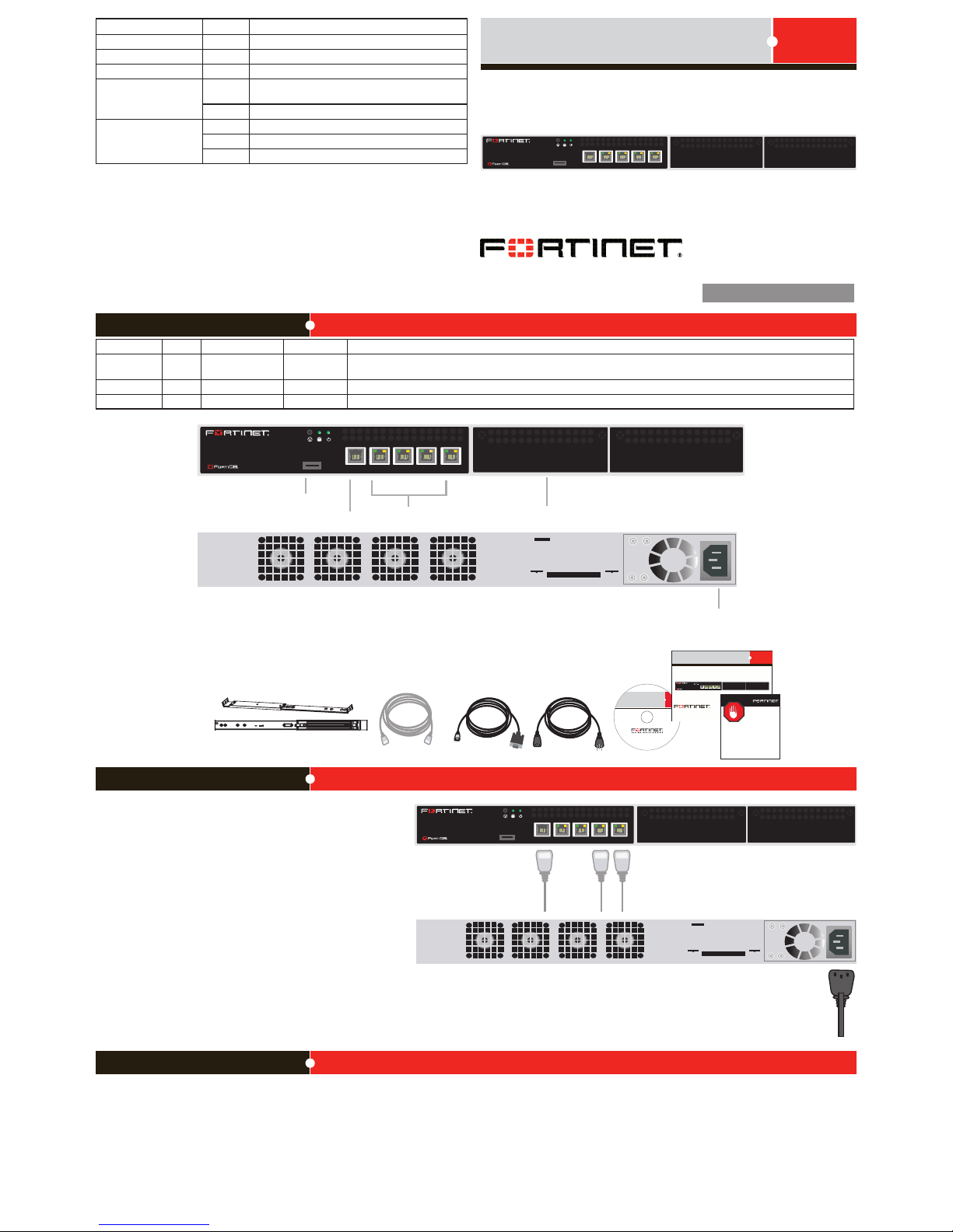
Connecting
1 2 3 4
USB
CONSOLE
400B
AC power
connection
Ethernet ports
Removable hard disk
USB
RJ-45 serial
connection
1 2 3 4
USB
CONSOLE
400B
Power cable
conne cts to
power suppl y
RJ-45 to DB -9 ser ial ca ble
conne cts to manag ement
compu ter
Ether net ca bles c onnect
to co mputer s on t he
inter nal ne twork
1 2 3 4
USB
CONSOLE
400B
Straig ht-through
Ethern et cable
Power Cable
RJ-45 to
DB-9 S erial Cable
FortiGate-30B
Tools and Documenation
Copyright 2009 Fo rtinet Inco rporated. All rights rese rved.
Trademarks
QuickStar t Guide
1 2 3 4
USB
CONSOLE
400B
REGISTER
Slidin g rail kit
Package Contents
Connect the following to the FortiDB unit. Ensure the FortiDB unit is placed
on a stable surface or install in a standard 19 inch rack.
• Insert one end of an Ethernet cable into port 1.
• Connect the other end of the Ethernet cable to the network hub or
switch.
• Connect the AC Power cable to the Power Supply on the back of the
FortiDB unit.
• Connect the other end of the Power cable to a surge protected
power bar or power supply.
FortiDB-400B
15-400-113531-20091110
QuickStart Guide
Web-based manager
The FortiDB web-based manager is an easy-to-use management tool.
Use it to congure the administrator password, the interface and default gateway addresses,
and congure reports.
Requirements:
• An Ethernet connection between the FortiDB unit and management computer.
• A web browser such as FireFox or Internet Explorer on the management computer.
Command Line Interface (CLI)
The CLI is a full-featured management tool. Use it to congure the administrator password,
the interface addresses, the default gateway address, and the DNS server addresses. To
congure advanced settings, see the Tools and Documentation CD included with the
FortiDB unit.
Requirements:
• The RJ-45 to DB9 serial connection between the FortiDB unit and management
computer.
• A terminal-emulation application such as HyperTerminal for Windows, on the
management computer.
Conguration Tools
Connector Type Speed Protocol Description
Ports 1 to 4 RJ-45 10/100/1000
Base-T
Ethernet Copper gigabit connection to 10/100/1000 copper networks.
CONSOLE RJ-45 9600 8/N/1 RS-232 serial Optional connection to the management computer. Provides access to the command line interface (CLI).
USB USB USB For future use.
LED State Description
Power Green The device is connected to a power source and on.
Hard Disk Amber Activity on the hard disk.
Alarm Red Hard disk failure.
Ports 1 to 4 Left LED
Green The correct cable is connected to the interface and
the connected equipment has power.
Flashing Network activity at this interface.
Ports 1 to 4 Right LED
Green The interface is connected at 1000 Mbps.
Amber The interface is connected at 100 Mbps.
Off The interface is connected at 10 Mbps.
Page 2

Visit these links for more information and documentation for your Fortinet product.
Technical Documentation - http://docs.forticare.com
Fortinet Knowledge Center - http://kb.fortinet.com
Fortinet Technical Support - http://support.fortinet.com
Training Services - http://campus.training.fortinet.com
Port Information
Port 1 IP: ____.____.____.____
Netmask: ____.____.____.____
Port 2 IP: ____.____.____.____
Netmask: ____.____.____.____
Port 3 IP: ____.____.____.____
Netmask: ____.____.____.____
Port 4 IP: ____.____.____.____
Netmask: ____.____.____.____
The internal interface IP address and netmask must be valid for the internal network.
Collecting Information
Conguring
Web-based Manager
Use the following procedure to connect to the web-based manager for the rst time. Conguration changes made with the Web Cong are effective immediately without resetting the unit
or interrupting service.
To connect to the web-based manager
1. Connect the Port 1 interface of the unit to Ethernet port of the management computer.
Use a cross-over Ethernet cable to connect the devices directly. Use straight-through
Ethernet cables to connect the devices through a hub or switch.
2. Congure the management computer to be on the same subnet as the Port 1 interface.
To do this, change the IP address of the management computer to 192.168.1.2 and the
netmask to 255.255.255.0.
3. To access the web-based manager, in your browser, go to https://192.168.1.99 (remember to include the “s” in https://).
4. Type admin in the Name eld, type fortidb1!$ in the Password eld, and click Login.
After connecting to the Web-based manager, you can congure the unit IP address, DNS
server IP address, and default gateway to connect the unit to the network.
To congure interfaces
1. Go to Appliance > Network > Interface.
2. Click the edit icon to congure each interface.
3. Set the IP address and netmask for the interface.
4. Click OK.
To congure the Primary and Secondary DNS server IP addresses
1. Go to Appliance > Network > DNS, enter the Primary and Secondary DNS IP addresses click Apply.
To congure a Default Gateway
1. Go to Appliance > Network > Static Routing and select Create New.
2. Set Gateway to the Default Gateway IP address and click OK.
General settings
Administrative account
settings
User name admin
Password fortidb1!$
Network Settings Default Gateway: ____.____.____.____
Primary DNS Server: ____.____.____.____
Secondary DNS Server: ____.____.____.____
A default gateway is required for the unit to route connections to the Internet.
Factory default settings
Port 1 interface 192.168.1.99
Port 2 interface
Port 3 interface
Port 4 interface
To reset the unit to the factory defaults, in the CLI type the command:
exec reset all-settings
Command Line Interface
The unit has serial port. Use the null modem cable to connect it to your management computer.
To connect to the unit
1. Use a null modem cable to connect the serial port to the management computer serial
port.
2. Start a terminal emulation program (such as HyperTerminal) on the management computer. Use these settings: Baud Rate 9600, Data bits 8, Parity None, Stop bits 1, Flow
Control None.
3. At the login prompt, type admin for the user name and fortidb1!$ for the password
and press Enter.
After connecting to the CLI, you can congure the unit IP address, DNS server IP address,
and default gateway to connect the unit to the network.
To congure the unit using the CLI
1. Set the IP address and netmask of the Port1 interface.
cong system interface
edit port1
set ip <intf_ip>/<netmask_ip>
set allowaccess ping https ssh http
next
edit port2
next
edit port3
next
edit port4
next
end
3. Congure the primary and secondary DNS server IP addresses.
cong system dns
set primary <dns-server_ip>
set secondary <dns-server_ip>
end
4. Congure the default gateway.
cong system route
edit 1
set device <interface>
set dst <destination_ip>
set gateway <gateway_ip>
end
Shutting down the unit using the CLI
Enter the following command at the prompt:
execute shutdown
 Loading...