

Page 1

FortiCam™ SD20 Mounting Guide
Page 2

Forti
April 14
Copyright © 201
FortiGuard®, and certain other marks are registered trademar
Fortinet names herein may also be registered and/or common law trademarks of Fortinet. A ll
other product or company names may be trademarks of their respective owners. Performance
and other metrics contained herein were atta
and actual performance an d other results may vary. Network variables, different networ k
environments and other conditions may affect performance results. Nothing herein represents
any binding commitment by
implied, except to the extent Fortinet enters a binding written contract, signed by Fortinet's
General Counsel, with a purchaser that expressly warrants that the identified produ ct will
p
identified performance met r ics and, in such event, only
the specific performance metrics expressly identified in such binding written contract shall be
binding on Fortinet. For absolute clarity, any such warranty will be limited to performance in the
same ideal conditions as in Fortinet's internal lab tests. Fortinet disclaims in full any covenants,
representations, and guarantees pursuant hereto, whether express or implied. Fortinet
reserves the right to change, modify
notice, and the most curr ent version of the publication shall be applicable.
Cam SD20 Mounting Guide
, 2016
6 Fortinet, Inc. All rights reserved. Fort inet®, FortiGate®, FortiCare® and
Fortinet, and Fortinet disclaims all warranties, whether express or
erform according to certain expressly-
ks of Fortinet, Inc., and other
ined in internal lab tests under ideal conditions,
, transfer, or otherwise revise this publication without
Technical Documentation docs.fortinet.com
Knowledge Base kb.fortinet.com
Customer Service & Support support.fortinet.com
Training Services training.fortinet.com
FortiGuard fortiguard.com
Document Feedback techdocs@fortinet.com
Page 3

Table of Contents
Warnings and Cautions ................................................................................... 4
Package contents ............................................................................................ 5
Connectors ....................................................................................................... 6
Camera Dimensions ........................................................................................ 7
Available Access ories ...................................................................................... 8
Ceiling Mount ................................................................................................. 12
Indoor convers io n ................................................................................................... 12
Hard ceiling mount.................................................................................................. 13
In-ceiling t-bar mount ............................................................................................. 15
Ceiling mount with straight t u be ............................................................................. 18
Wall Mount ...................................................................................................... 20
Standard pendent mount ........................................................................................ 20
Corner Mount ................................................................................................. 22
Corner plate ............................................................................................................ 22
Pole Mount ..................................................................................................... 23
Pole direct mounting ............................................................................................... 23
Page 4

Warnings and Cautions
• Handle the camera carefully
Do not abuse the camera. The camera can be damaged by improper handing or storage.
• Do not disassemble the camera
To prevent electric shock, do not remove screws or covers. There are no user serviceable
parts inside. Ask a qualified service person for servicing.
• Do not block cooling holes on the bracket
This camera has a cooling fan inside. Blo cking the cooling holes leads to buildup of heat,
and may cause malfuncti on.
• Do not operate the camera beyond the specified temperature, humidity or power
source ratings
Use the camera under conditions where temperature is between 0°C ~ 40°C (32°F ~ 104°F),
and relative humidity is below 90%.
• Do not expose the camera to rain or moisture, or try to operated it in wet areas
This product is designed for indoor use or locations where it is protected from rain and
moisture. Turn the power o ff immediately if the camera i s wet and ask a qualified service
person for servicing. Moisture can damage the camera and also cause electric shock.
• Do not use strong or abrasive detergents when cleaning the camera body
Use a dry cloth to clean the camera wh en it is dirty. In case the dirt is hard to remove, use a
mild detergent and wipe the camera gently.
• Never face the camera towards the sun
Do not aim the camera at bright objects. Whether the camera is in use or not, never aim it
at the sun or other extremely bright objects. Otherwise, the camera may be smeared or
damaged.
4
Page 5
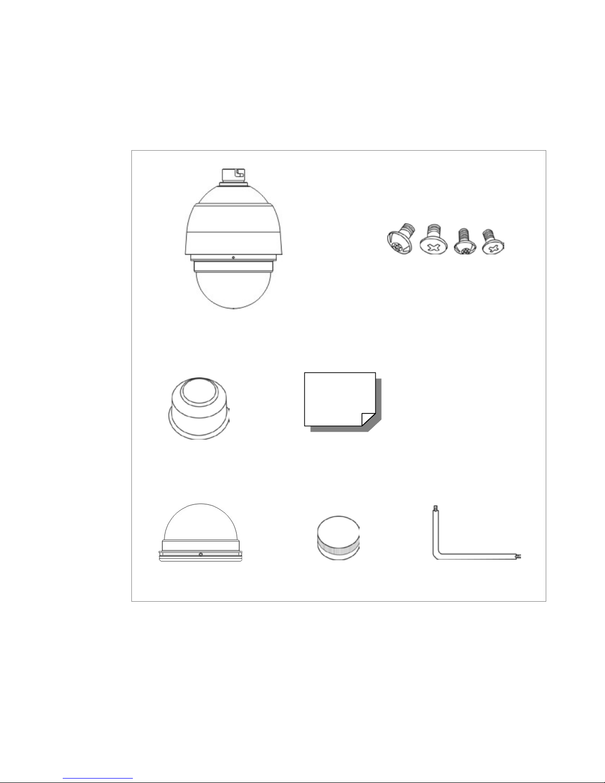
Package contents
Before proceeding, check the box for the following items. If any item is missing or is defective,
DO NOT install or operate the product. Contact the dealer for assistance.
Camera Body with
Outdoor Mount Kit
M3 Standard Screw x 1
M3 Security Screw x 1*
M5 Standard Screw x 1
M5 Security Screw x 1*
Waterproof Rubber
Optical Cover
QuickStart Guide
Lubricant
Security Torx*
5
Page 6
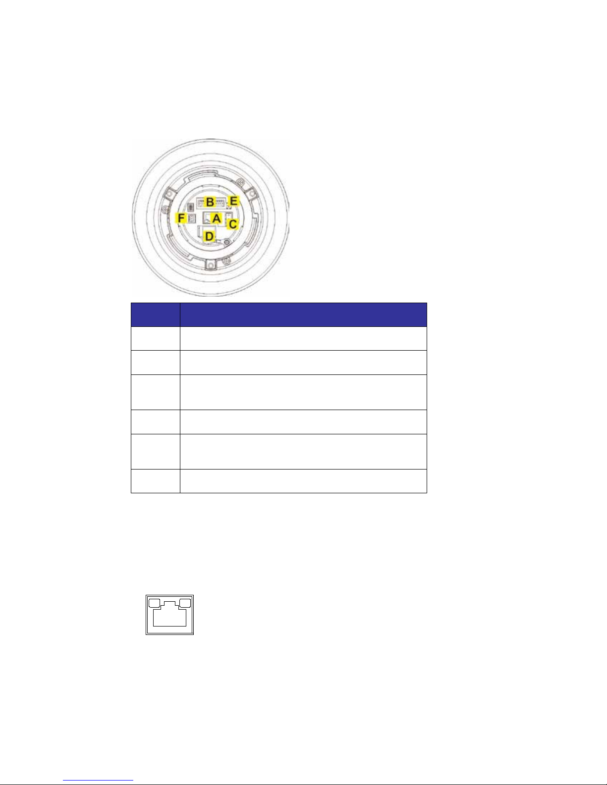
Connectors
There are various connectors located on the back of the dome camera.
Pin Connecter
A RJ-45 Connector for Ethernet and PoE connections
B Alarm I/O Connector
C Power (AC 24V) Connector (power adaptor not
supplied)
D microSD Card Slot (not in use)
E Factory Reset Button: Press for at least 20 seconds
to reset the system
F Audio I/O Connector
A category 5 ethernet cable is recommended for network connection. To have the best
transmission quality, the cable length should not exceed 100 meters. Connect one end of the
ethernet cable to the RJ-45 connector of the camera and the other end of the cable to a PoE
switch.
Check the status of the link indicator and activity indicator LEDs. If the LEDs are off, check the
LAN connection.
• A green link light indicates a good network connection.
• A flashing orange activity light indicates network activity.
6
Page 7
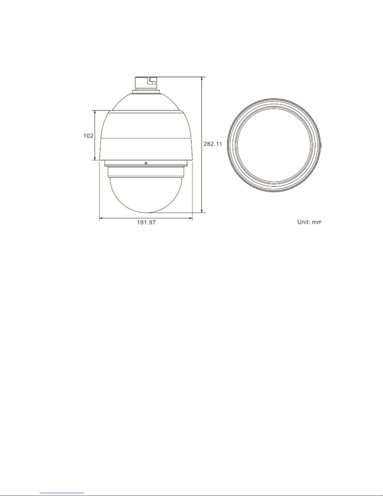
Camera Dimensions
7
Page 8
Available Accessories
You can order any of the following mounting accessories for your installation requirements:
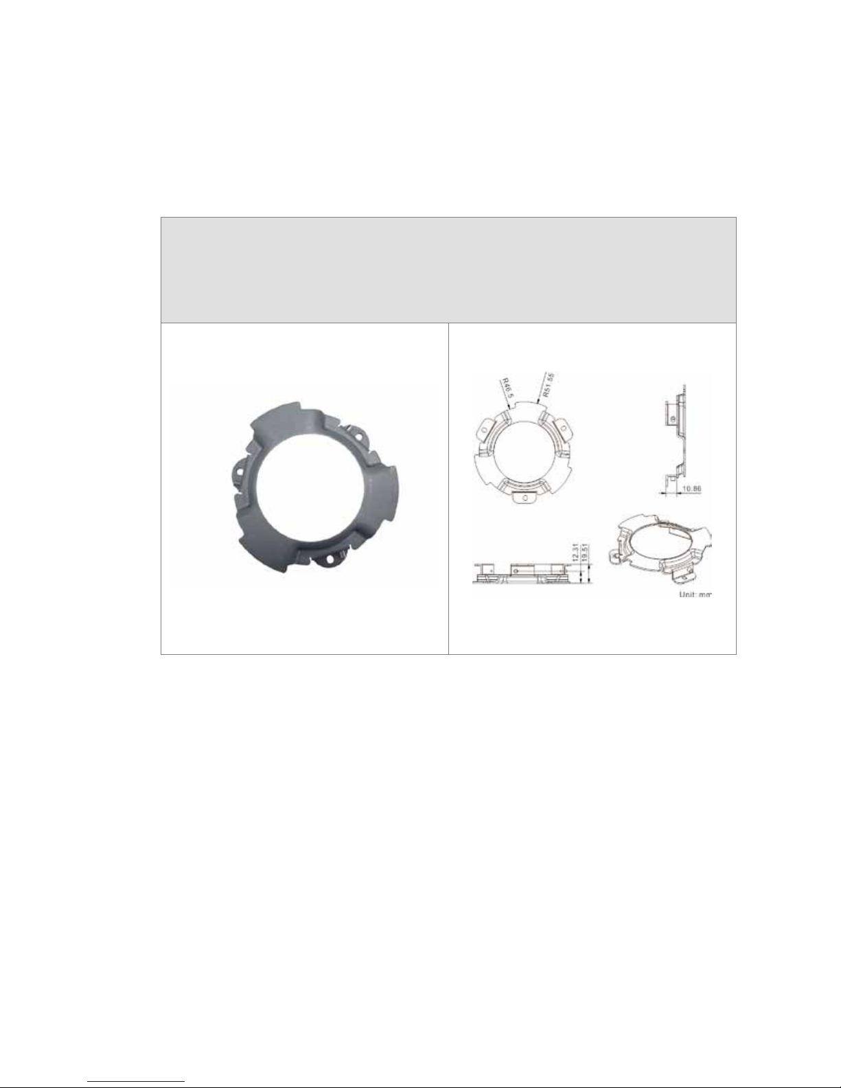
Hard Ceiling Mount (SKU: FCM-SD2-HCM)
For Hard Ceiling Installation
Height: 19.51 mm (0.77 inche s ); Diameter of the bracket: 103.1 mm (4.06 inches)
Weight: 65.0 g (0.14 Ibs)
8
Page 9

In-Ceiling (T-Bar) Mount (SKU: FCM-SD2-ICT)
For In-Ceiling Installation
Height: 166.11 mm (6.54 inches); Diameter: 276.0 mm (10.9 inches)
Weight: 1.1 kg (2.4 lbs)
Standard Pendent Mount (SKU: FCM-SD2-PDT)
White; 348.0 x 104.0 x 138.6 mm (13.7 x 4.1 x 5.5 inches); 1.5 kg (3.3 lbs)
Diameter: 45.0 mm (1.8 inches)
Supplied with M8x12 screw x 1, spring washer-8 x 1, pendent tube washer x 1,
rubber washer-8 x 1 and sponge x 2.
9
Page 10

Straight Tube (SKU: FCM-SD2-ST25)
Iron; Height: 250.0 mm (9.8 inches)
Diameter: 50.0 mm (2.0 inches) 1.0 kg (2.2 lbs)
Supplied with M8x12 screw x 1, spring washer-8 x 1, pendent tube washer x 1,
rubber washer-8 x 1 and waterproof rubber x 1
Corner Standard Mounting Plate (SKU: FCM-SD2-CPM)
222.0 (L) x 204.0 (W) x 117.0 (D) mm (8.7 x 8.0 x 4.6 inches); 2.0 kg (4.4 lbs)
Supplied with washer-8 x 4, spring washer-8 x 4, M8x16 screw x 4, and M8 nut x 4
10
Page 11

Pole Thin Direct Mounting Plate (SKU: FCM-SD2-TDM)
For mounting with Standard Pendant Mount
232.0 (L) x 136.0 (W) x 50.0 (D) mm (9.1 x 5.4 x 2.0 inches)
Diameter: 50.0 ~ 200.0 mm (2.0 ~ 7.9 inches); Weight: 0.7 kg (1.5 lbs)
Supplied with stainless steel straps x 4, Mx16 screw x 4, washer x 4 and spring washer-8 x
4
Stainless Steel Straps
For fixing pole
232.0 (L) x 136.0 (W) x 50.0 (D) mm (9.1 x 5.4 x 2.0 inches)
Diameter: 50.0 ~ 200.0 mm (2.0 ~ 7.9 inches); Weight: 0.7 kg (1.5 lbs)
Supplied with stainless steel straps x 4, Mx16 screw x 4, washer x 4 and spring washer-8 x
4
11
Page 12

Ceiling Mount
There are three ceiling mounting methods:
• Hard-ceiling mounting
• In-ceiling mounting
• Mounting with the straight tube
See the following sections for more details.
Indoor conversion
The FortiCam SD20 camera is designed to be placed outdoors. If you want to install it on
indoor ceilings, using the hard-ceiling or in-ceiling mounting, you must modify it using the
conversion accessories supplied with those kits. For straight tube mounting, no matter indoor
or outdoor, you do not need to modify the camera.
To convert the camera from outdoor t o indoor usage:
1. Remove the three screws from the top of the
sunshield to detach the sunshield.
2. Rollback the rubber seal to expose the three
screws. Once exposed, loosen the three
screws.
12
Page 13

Once you have removed the sunscreen,
screws, and the ring, your camera will resemble
this.
3. Place the metal hook between the plastic
ring and the top of the camera.
4. Attach the top of the camera and tighten the
three screws.
Hard ceiling mount
If you have hard ceilings, like concrete, use the hard ceiling mount accessory.
Note: You must order the mounting accessories separatel y from Fortinet.
Tools Needed:
• Drill
• (+,–) Screw driver
13
Page 14

To mount the camera on a hard ceiling
1. Mark the positions of the three screw holes on
the ceiling using the mount as a guide.
2. Drill a hole in each marked location.
3. Insert the supplied anchors into the drilled holes
and then fasten the hard ceiling mount with the
three supplied self-tapping screws .
4. Thread the data cable and Ethernet cable through the center hole of the mount and
connect the cable to the camera body.
5. You can choose to hide the data cable and
Ethernet cable inside the ceiling, and use the
rubber from the accessory package to fill the gap
at the side of the fixing plate. You can also lead
the cables out from the gap on the side of the
fixing plate (as shown in the diagram).
6. Install the camera on the hard ceiling mo unt by
turning the camera counterclockwise and then
tightening the screw at the side of the fixing plate.
7. Install the dome cover and then fasten the
supplied standard screw on the dome cover.
Note: Use the security screw fo r the vandal proof
dome.
14
Page 15

In-ceiling t-bar mount
If you have a hanging or hollow ceiling, use the hard ceiling mount accessory and the T-bar
mount accessory.
Note: You must order the mounting accessories separatel y from Fortinet.
Tools Needed:
• Jigsaw or knife
• (+,–) Screw driver
To mount the camera into a ceiling with T-bar
1. Install the camera on the hard ceiling mount by
turning the camera counterclockwise.
2. Tighten the screw at the side of the fixing plate.
15
Page 16

3. Install the camera on the T-bar bottom mount.
4. Place the ceiling mounting template sticker on the
ceiling and cut the ci r cle part out of the ceiling.
5. Disassemble the wings from the in-ceiling (t-bar)
mount by loosening the three screws
counterclockwise, as indicated in the picture.
6. Loosen the screws until the wings are loose
enough to be turned outward from the ring, as
indicated in the picture.
7. Insert the t-bar bracket into the ceiling openin g
and fix the in-ceiling (t-bar) mount on the ceiling
by tightening the three screws.
16
Page 17

8. When screwing, the wings will approach the
ceiling board until it is completely flush with the
board.
Note: Make sure the wings of the T-Bar Bracket
are completely flush with the ceiling board.
9. Place the power cabl e and Ethernet cable down through the center hole of the t-bar
and connect the cable to th e camera.
10. Insert the installed t-bar bottom mount with the
camera in the ceiling opening.
11. Tighten the screws to fix the t-bar bottom mount
to the t-bar bracket.
17
Page 18

12. Fix the trim ring to the t-bar bracket.
Ceiling mount with straight tube
Tools Needed:
• Drill
• Screwdriver
To mount the dome camera with the straight tube
Warning: Make sure the ceiling can support the weight of t he dome camera and straight tube.
1. Make a cable entry hole in the ceiling.
2. Fix the suspension bracket to the ceiling with the proper screws and anchors.
3. Thread the cables through the straight tube and the mounting kit.
Note: After threading the cables, block the cable entry ho le with the supplied
sponge(s) to prevent outside materials from entering the tube.
1. Fix the mounting kit to the straight tube with the supplied screws and washers.
2. Connect the cables to the dome camera.
3. Mount the dome camera to the mounting kit, making sure to align the thread holes of
the lock screw plate and mounting kit.
4. Align the thread holes on the lock screw plate
and mounting kit and screw the supplied M5
standard screw/security to the plate as shown in
the picture.
18
Page 19

Ceiling mounting: straight tube
19
Page 20

Wall Mount
The dome camera can be mounted on the wall with the standard pendent mount.
Standard pendent mount
Follow the steps below to mount the dome camera to the standard pendant mount.
Tools Needed:
• Drill
• Screw driver
To mount the dome camera to the pendant mount
1. Make a cable entry hole on the wall to recess the
cables. Alternati vely, you could place the cable
entry board on the compact pendent mount’s
mounting plate to place the cables as shown in
the picture.
2. Fix the pendent mount on the wall with the proper screws and anchors.
3. Attach the waterproof rubber to the pendant mount.
4. Run the cable(s) through the pendant mount.
Note: Block the cable entry hole with the
supplied sponge to prevent outside materials
from entering the mount. The sponge can be
placed in the mount in two different ways, as
shown in the pictures.
5. Thread the cable(s) through the mounting kit and join the mounting kit to the pendent
mount with the supplied screws and washers. Adjust the waterproof rubber to the
joint.
6. Connect the cable(s) to the dome camera.
20
Page 21

7. Join the dome camera to the mounting kit with the supplied screw and washers.
Wall mounting: pendent mount and mounting kit
21
Page 22

Corner Mount
The corner mount allows you to attach the camera to the corners of walls to provide maximum
surveillance. It is designed to work with the pendent mount available separately.
Corner plate
Follow the steps below to mount the dome camera to the corner plate.
Tools needed:
• Drill
• Screw driver
To mount the dome camera to the corner plate
1. Make a cable entry hole on the wall to recess the cable(s).
2. Fix the corner pl ate on the corner of the wall with the proper screws and anchors.
3. Run the cable(s) through the hole on the corner plate.
4. Fasten the corner plate with the supplied screws and washers and then thread the
cable(s) through the corner plate with the cable(s) coming out of the pendent mount’s
outlet.
Note: Block the cable entry hole with the supplied sponge to prevent outside
materials from entering the pendent mount.
5. Attach the waterproof rubber to the corner plate.
6. Thread the cable(s) through the mounting kit and join the mounting kit to the corner
plate with the supplied screws and washers. Then adjust the waterproof rubber to
the joint.
7. Connect the cable(s) to the dome camera.
8. Join the dome camera to the mounting kit with the supplied screws and washers.
Corner wall mounting: standard corner plate and pendent mount kit
22
Page 23

Pole Mount
The dome camera can be mounted on a pole using the provided pole mou nting kit. It is
designed to work with the pendent mount available separately.
Pole direct mounting
Follow the steps below to mount the dome camera to the pole direct mounting plate.
Tools needed:
• Stainless strap cutter
• Screw driver
To mount the dome camera to a pole
1. Fasten the direct mounting plate to a pole with the equipped stainless straps.
2. Run the cable(s) through the hole on the direct mounting plate.
3. Fasten the standard pendent mount to the pole direct mounting plate with the
supplied screws and washers.
4. Thread the cable(s) through the pendent mount with the cable(s) coming out of the
pendent mount’s outlet.
Note: Block the cable entry hole with the supplied sponge to prevent outside
material from entering the pendent mount.
5. Attach the waterproof rubber to the pendent mount.
6. Thread the cable(s) through the mounting kit and install the mounting kit to the
pendent mount with the supplied screws and washers. Adjust the waterproof
rubber to the joint.
7. Connect the cable(s) to the dome camera.
8. Install the dome camera to the mounting kit with the supplied screws and washers.
23
Page 24

Pole direct mounting with standard pendent mount
24
Page 25

25
 Loading...