

Fortinet FortiCam 20A Quick Start Manual

FortiCam 20A
QuickStart Guide

December 19, 2012
1st Edition
Copyright © 2012 Fortinet, Inc. All rights reserved. Fortinet®, FortiGate®, and FortiGuard® are
registered trademarks of Fortinet, Inc., and other Fortinet names herein may also be trademarks
of Fortinet. All other product or company names may be trademarks of their respective owners.
Performance metrics contained herein were attained in internal lab tests under ideal conditions,
and performance may vary. Network variables, different network environments and other
conditions may affect performance results. Nothing herein represents any binding commitment
by Fortinet, and Fortinet disclaims all warranties, whether express or implied, except to the
extent Fortinet enters a binding written contract, signed by Fortinet’s General Counsel, with
a purchaser that expressly warrants that the identified product will perform according to
the performance metrics herein. For absolute clarity, any such warranty will be limited to
performance in the same ideal conditions as in Fortinet’s internal lab tests. Fortinet disclaims
in full any guarantees. Fortinet reserves the right to change, modify, transfer, or otherwise
revise this publication without notice, and the most current version of the publication shall be
applicable.
Technical Documentation http://docs.fortinet.com
Knowledge Base http://kb.fortinet.com
Forums https://support.fortinet.com/forum
Customer Service & Support https://support.fortinet.com
Training Services http://training.fortinet.com
FortiGuard Threat Research & Response http://www.fortiguard.com
Document Feedback Email: techdocs@fortinet.com

Table of contents
Package contents 1
Hardware installation 2
Technical specifications 8
Compliance 10
License agreement 12
Page 1
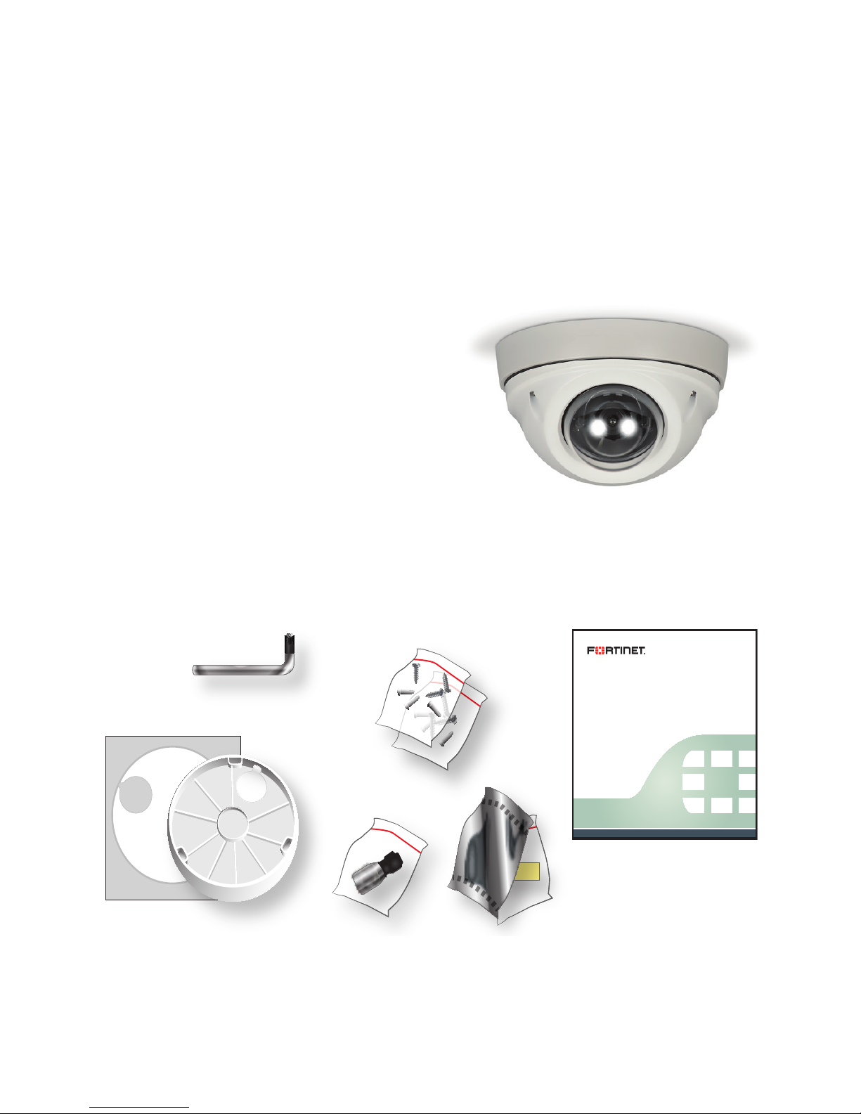
Package contents
Your box should contain:
FortiCam 20A
QuickStart Guide
Security Torx wrench
Wall anchors
Mounting screws
Mounting base
Drilling template
Weatherproofing shell for male RJ-45 connector
Extra silica gel packet (dry bag) for very humid areas
FortiCam 20A
QuickStart Guide
QuickStart GuideSecurity Torx Wrench Screws and Anchors
(1 Short; 1 Long)
Silica Gel
Waterproofing Shell
Drilling Template
Mounting
Base

Page 2
Hardware installation
FortiCamera cameras can be mounted on walls or ceilings, in a variety of
lighting and weather. Connect the camera to your network via Power over
Ethernet (PoE).
For best results, choose a location where the cable can enter the wall or
ceiling directly behind the camera (i.e. it does not run outside, along the
surface), and where the camera is not easily reached. This deters vandals
from damaging the cables or covering the camera. For extra protection,
house the cables in conduit.
Caution: In many countries, surveillance is restricted by law. Before
installing, if you are uncertain of applicable privacy/security laws, consult
your legal advisor.
Environmental specifications
• Operating temperature: -20 - 50°C (-4 - 122°F) If you install this
device in a closed container, the operating ambient temperature of the
container may be greater than room ambient temperature. Therefore,
make sure to install the equipment in an environment compatible with
the maximum rated ambient temperature (Tma).
• Humidity: 10 to 80% non-condensing
• Interference: Shielded Twisted Pair (STP) Ethernet cables should be
used whenever possible rather than Unshielded Twisted Pair (UTP).
Page 3
Safety warnings
• Grounding: Do not connect or disconnect cables during lightning; this
may damage your device or cause personal injury. Connections that
enter from outside the building should pass through a lightning and
surge protector, and be properly grounded. To prevent damage to your
equipment, use an electrostatic discharge (ESD) workstation and/or
wearing an anti-static wrist strap when handling.
• PoE: Do not connect this device to PoE networks with routing to the
outside plant. Do not use PoE injectors that are not IEEE 802.3af
compliant.
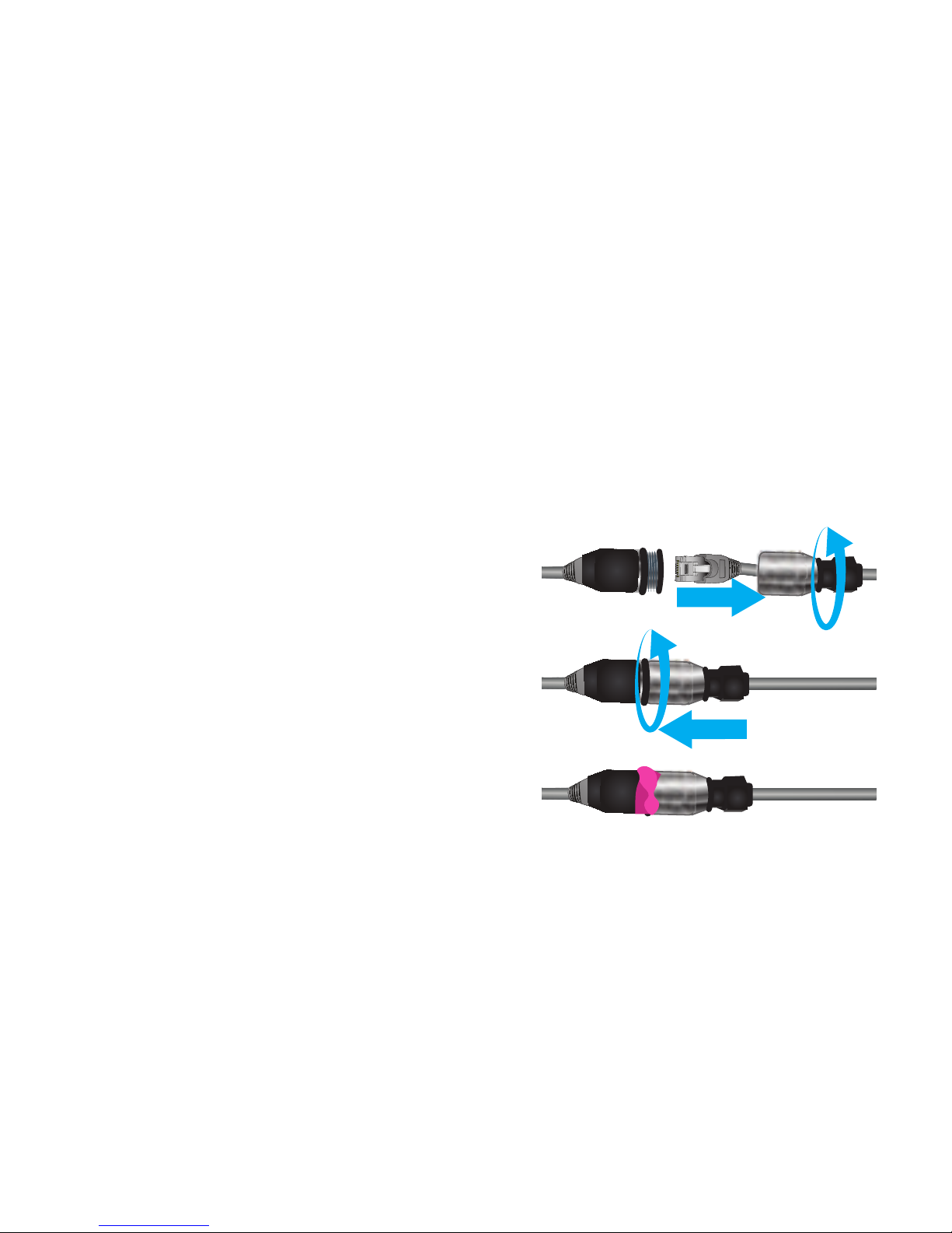
To weatherproof your PoE connection
1. Disassemble the gasket and RJ-45
connector from waterproofing shell.
2. Cut off the your network cable’s
male RJ-45 connector. (Do not cut
the camera’s.)
3. Thread the cable through the
waterproofing shell and gasket.
4. Crimp shell’s male RJ-45 connector
onto the cable. (Consult crossover cable wiring diagrams if needed.)
5. Retract the connector into the gasket. Twist the nut to secure the shell.
6. After the PoE cables are connected, twist the male waterproofing shell
together with the camera’s female end. Over where they meet, wrap
waterproofing tape (not included) to prevent water from seeping inside.
Page 4
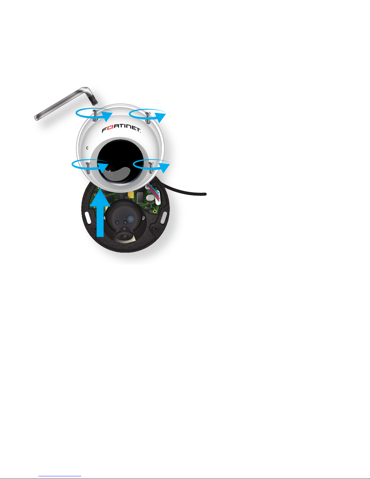
To mount your camera
1. Using the security Torx key,
loosen the 4 security screws
on the housing. The screws will
not come out completely, but
enough to detach the base.
2. Remove the dome cover.
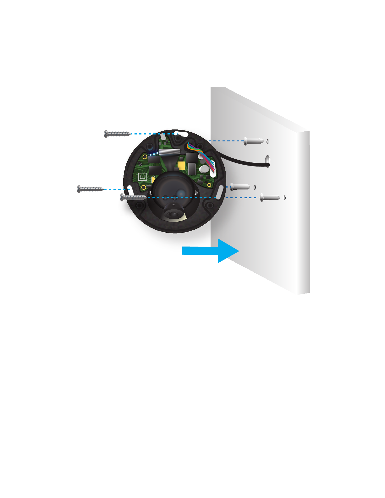
3. Using the template as a
guide, pre-drill pilot holes in the
wall/ceiling, then hammer the
plastic anchors into the holes.
(If possible, for more secure
mounting, omit the anchors;
instead, pre-drill holes into a
framing stud.)
4. If your network cables are inside the wall/ceiling, drill a hole large
enough to pass the camera’s cable through the wall/ceiling. Thread the
camera’s PoE cable though the hole. (If using the optional mounting
base, thread the PoE cable through the base, then through the hole
in the wall.)
5. Plug the your network cable into the camera’s PoE connector.
6. Hold the camera to the wall/ceiling, aligning its mounting holes with the
holes in the wall/ceiling.
Page 5
7. Insert the 3 screws through each elongated hole in the camera base
(and, optionally, mounting base), then twist the screws into the wall
anchors or stud. Tighten the screws with a screwdriver until the
camera base is firmly in place. If using the mounting base, use the
longer screws, not the shorter ones.
Page 6
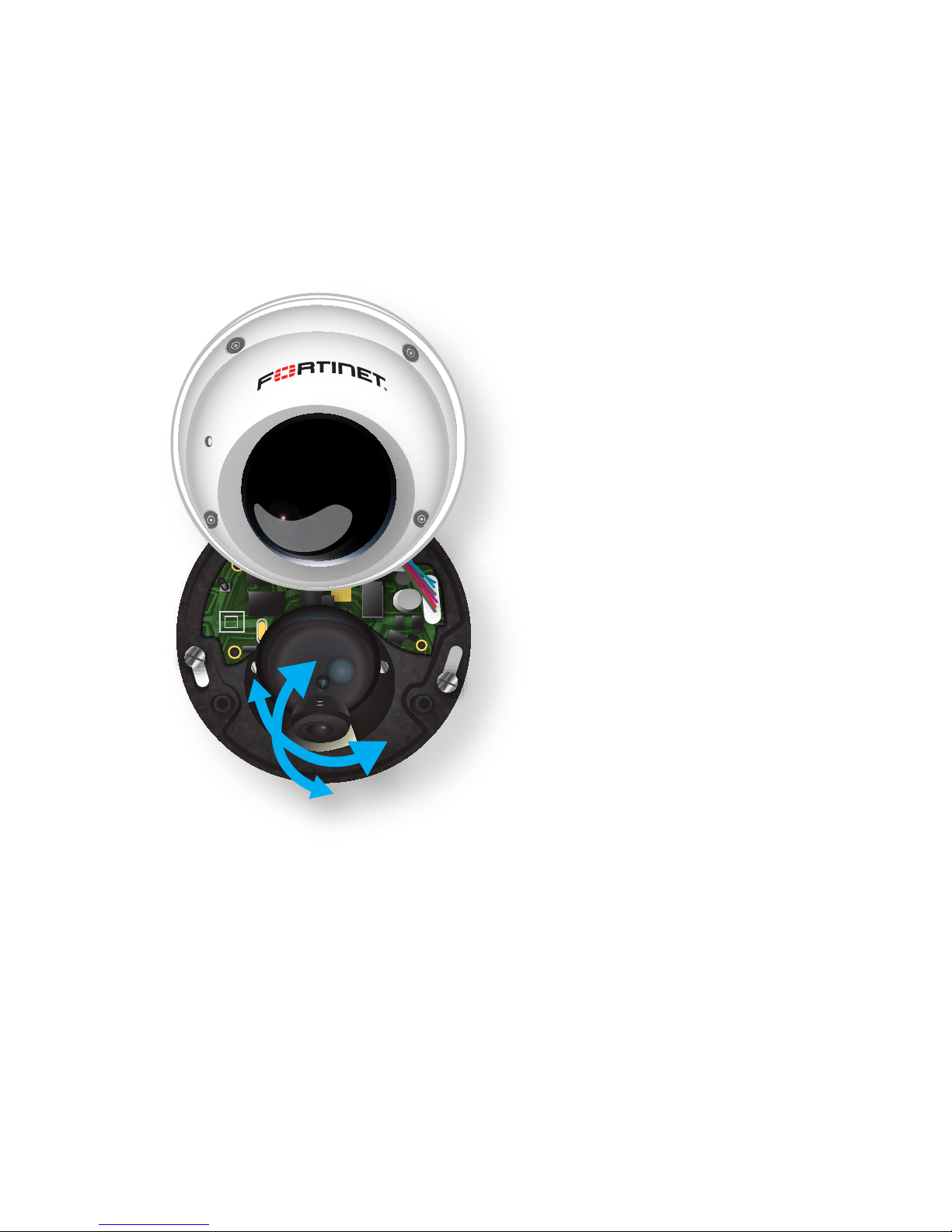
8. If it is necessary to aim the camera, gently grip the lens orb between
two fingers, and move it to adjust the orientation.
9. Replace the cover. Tighten
the 4 security Torx screws to
secure the housing.
10. Connect your camera
with your NVR and
configure according to the
FortiCameraHandbook.
 Loading...