

Fortinet FortiBridge FortiBridge-1000 Quick Start Manual
LED Indicators
LED State Description
PWR Green The FortiBridge unit is powered on.
Off The FortiBridge unit is powered off.
INT 1
INT 2
EXT 1
EXT 2
Green The correct cable is in use and the
connected equipment has power.
Flashing Green Network activity at this interface.
Off No link established or the interface has
been turned off.
INT 1
INT 2
EXT 1
EXT 2
(back)
Green The correct cable is in use, and the
connected equipment has power.
Flashing amber Network activity at this interface.
Off No link established.
Default settings
Administrator account admin
Password (none)
Management IP 192.168.1.99
Netmask 255.255.255.0
Management Access Telnet and ping acce ss to the IN T 1
interface.
FortiBridge-1000
INT 1
EXT 1
EXT 2
BYPASS MODE
NORMAL
PWR
EscEnter
FortiGate
INT 2
MODE FACTORY RESET
QuickStart Guide
The FortiBridge unit functions as a pass-through device when a
FortiGate unit or FortiGate HA cluster operating in Transparent mode
fails or loses power. The FortiBridge unit bypasses the FortiGate unit to
make sure that the network can continue processing traffic. The
FortiBridge unit is not a firewall or antivirus device. FortiGate services
are not applied when the FortiBridge unit bypasses traffic.
© Copyright 2006 Fortinet Incorporated. All rights reserved.
Trademarks
Products mentioned in this document are trademarks or registered trademarks of their
respective holders.
Regulatory Compliance
FCC Class A Part 15 CSA/CUS
9 November 2006
09-30000-0164-20061109
Checking the package contents
1
Connector Type Speed Protocol Description
INT 1 & EXT 1 RJ-45
INT 2 & EXT 2 RJ-45
10/100/1000
Base-T
10/100/1000
Base-T
CONSOLE RJ-45 9600 bps
Ethernet
Ethernet
RS-232
serial
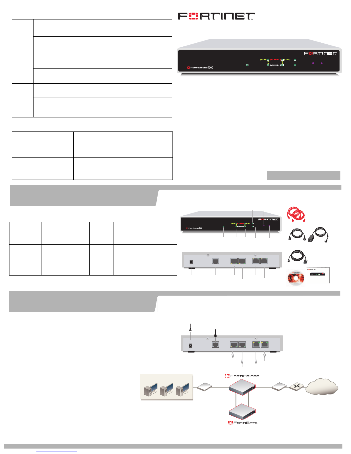
Connecting the FortiBridge-1000
2
Normally, you would use straight-through ethernet
cables to connect the FortiBridge-1000 unit. However,
for some connections you may need a crossover
ethernet cable (for example, for compatibility with
network devices that do not support Auto MDI/MDIX).
1. Connect the FortiBridge INT 2 interface to the
FortiGate unit internal interface.
2. Connect the FortiBridge EXT 2 interface to the
FortiGate unit external interface.
3. Connect the FortiBridge INT 1 interface to the
internal network.
4. Connect the FortiBridge EXT 1 interface to the
external network.
5. Turn on the FortiGate unit and any network
equipment that was turned off.
6. Connect the AC adapter to the power connection at
the back of the FortiBridge unit and to a power outlet.
The PWR and Bypass Mode LEDs turn on. After a short
time, the FortiBridge unit switches to Normal mode. The
Bypass LED turns off and the Normal LED turns on.
Copper gigabit ethernet
connections to the network.s
Copper gigabit ethernet
connections to FortiGate unit
interfaces.
Console connection to the
command line interface (CLI).
Check that the package contents are complete.
Front
PWR STATUS
PWR
Power
DC+5V
PWR
Power
CONSOLE
Console
Connection
Connect the FortiBridge unit to the internal and external networks and the
FortiGate unit. Connect the power cable to the FortiBridge unit.
Power cable connects to power supply
Optional RJ-45 serial cable connects to management computer
DC+5V
Switch
CONSOLE
INT 1
INT 2
Internal
(Transparent mode)
PWR
Ethernet connection to FortiGate External interface
Ethernet connection to FortiGate Internal interface
Internal network
INT 1
EXT 1
EscEnter
FortiGate
EXT 2
INT 2
INT 1
EXT 1
INT 2
EXT 2
Back
TO FORTIGATE
INT 2
EXT 2
EXT 2
INT 2
FortiGate unit
connections
TO FORTIGATE
INT 2
EXT 2
Change
Bypass
Mode
Mode
BYPASS MODE
MODE FACTORY RESET
NORMAL
Factory
Normal
Reset
Mode
INT 1EXT 1
EXT 1
INT 1
Network
connections
INT 1EXT 1
Ethernet connection to Internal network
Ethernet connection to External network
EXT 1
EXT 2
External
Switch
Power Cable
USER MANUAL
Documentation
Router
2 Orange Crossover
Ethernet Cables
Power Supply
RJ-45 to
DB-9 Serial Cable
FortiBridge-1000
INT 1
EXT 1
BYPASS MODE
MODEFACTORY RESET
EscEnter
NORMAL
PWR
FortiGate
INT 2
EXT 2
QuickStart Guide
Copyright 2005 Fortinet Incorporated. All rights reserved.
Trademarks
Products mentioned in this document are trademarks.
Internet

Collecting information
Collecting information
4
3
FortiBridge configuration settings
Administrator password
Management IP address/netmask
Default route
Primary DNS IP address
Secondary DNS IP address
Collect information you need to set up the FortiBridge unit for your network.
Configure the FortiBridge unit from the command line interface (CLI).
Connecting to the CLI
1. Connect the FortiBridge console port to the serial communications port
on your computer.
2. Start a terminal emulation program (HyperTerminal) on the
management computer. Use these settings: Baud Rate (bps) 9600,
Data bits 8, Parity None, Stop bits 1, and Flow Control None.
3. Press Escape to display the login prompt.
4. At the Login: prompt, type admin and press Enter twice (no password
required).
Basic configuration
Complete the basic FortiBridge unit network configuration.
4
1. Change administrator password.
config system admin
edit admin
set password <password>
end
2. Change the Management IP address.
config system manageip
set ip <mng_ip>/<netmask>
end
Probes and Alerts
5
Probes
Configure probe settings to set actions on failure, add a dynamic IP
pattern used by the probe packets, and enter the serial number of the
FortiGate unit. Actions on failure can include failing open and sending
an alert email, a syslog message, and an SNMP trap.
config probe setting
set action_on_failure alertmail failopen snmp syslog
set dynamic_ip_pattern #.#.#.*
set fgt_serial <FortiGate_serial>
end
Enable ping, HTTP, FTP, POP3, SMTP, and IMAP probes. Optionally
change the failure threshold and probe interval for each probe.
Enable the ping probe to send ping packets through the FortiGate unit.
config probe probe_list ping
set status enable
end
Enable the HTTP probe and change the failure threshold and probe
interval.
config probe probe_list http
set status enable
set failure_threshold 5
set probe_interval 8
end
You can also change HTTP, FTP, POP3, SMTP, and IMAP probe port
numbers. See the FortiBridge Administration Guide for details.
Probes monitor the FortiGate unit by sending packets from the INT 2 interface
through the FortiGate unit to the EXT 2 interface. If probe packets are not
received at the EXT 2 interface the FortiBridge unit detects a failure.
3. Change DNS server IP addresses.
config system dns
set primary <dns-server_ip>
set secondary <dns-server_ip>
end
4. Add the default route.
config system route
edit 1
set gateway <gateway_ip>
end
Alerts
Configure alert email.
config alertemail setting
set server mail.myorg.com
set username user@company.com
set password PassWORD
set mailto1 user@company.com
end
Add the IP address of a syslog server that receives FortiBridge
syslog messages.
config log syslogd setting
set server 172.20.120.11
end
Add an SNMP community and add the IP address of a SNMP
manager to the community
config system snmp community
edit 1
set name snmp_community
config hosts
edit 1
set ip 192.168.20.102
end
end
Technical support
6
Visit these links for more information and documentation for your Fortinet product.
Fortinet Technical Support Web site: http://support.fortinet.com
Fortinet Knowledge Center: http://kc.forticare.com
Technical Documentation: http://docs.forticare.com
 Loading...