

Page 1
ONE
VEHICULES
ANNÉES
Immobilizer bypass
Contournement
d’immobilisateur
Lock
Unlock
Arm
Disarm
Tachometer
Door Status
Trunk Status
Hand-Brake Status
Foot-Brake Status
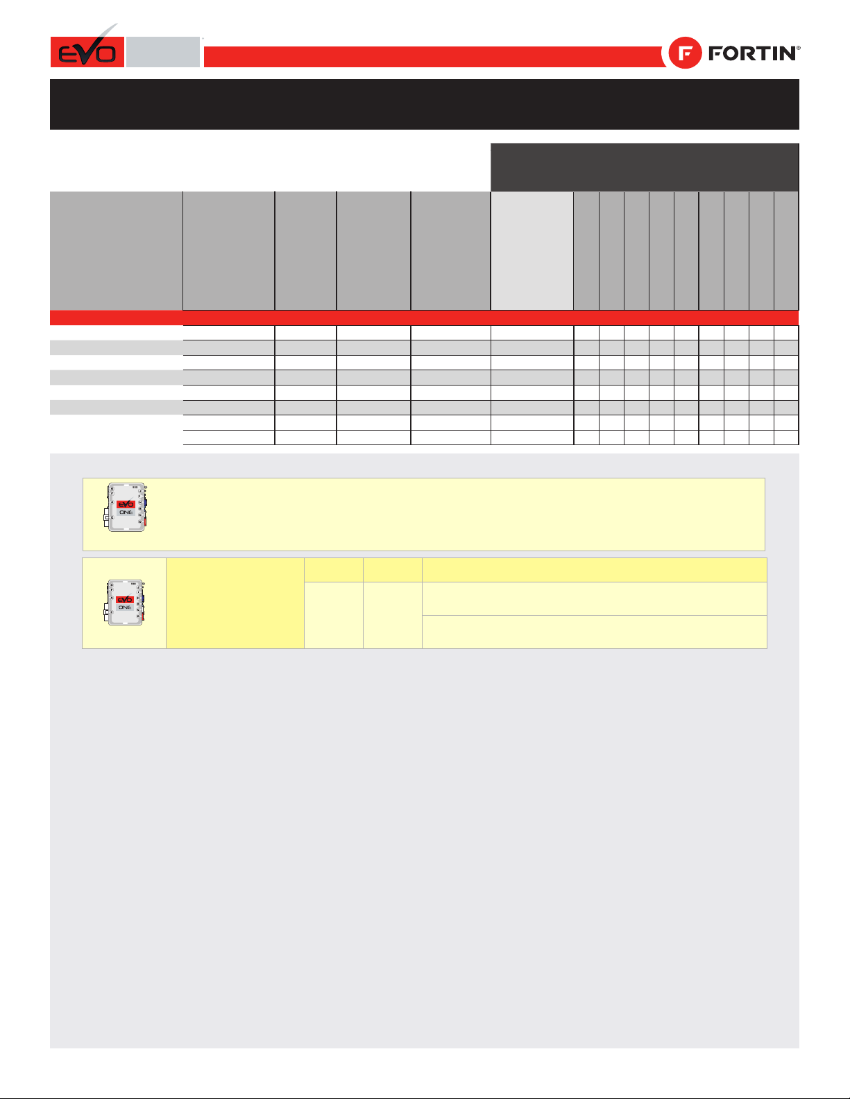
MAZDA
2
2011-2014
1G21
•
•••••••••
3 - Axela
2010-2013
1F21
•
•••••••••
5
2011-2014
1F21
•
•••••
6 - Atenza
2009-2013
1E21
•
•••••••••
CX-7
2007-2012
1F21
•
•••••••••
CX-9
2007-2015
1F21
•
•••••••••
Tribute
2001-2007
1C21
•
•••••
2008-2011
2C21
•
•••••••••
Page 1 / 10
REV.: 20180301
Guide # 29661
REGULAR INSTALLATION
INSTALLATION RÉGULIÈRE
VEHICLE
YEARS
Connection
BYPASS FIRMWARE VERSION
VERSION LOGICIELLE CONTOURNEMENT
71.[44
FORD MINIMUM
1KEY Programming
Programmation 1 clé
OR / OU
]
ADDENDUM - SUGGESTED WIRING CONFIGURATION
“Vehicle functions supported in this diagram (functional if
equipped) | Fonctions du véhicule supportées dans ce dia-
2KEY Programming
Programmation 2 clés
ADDENDA - SCHÉMA DE BRANCHEMENT SUGGÉRÉ
gramme (fonctionnelles si équipé)”
This manual may change without notice.
www.fortinbypass.com for latest version.
Ce Guide peut faire l’objet de changement
sans préavis. www.fortinbypass.com pour la
récente version.
Program remote
starter option:
Programmez l’option
démarreur à distance:
FUNCTION
FONCTION
31 4
MODE
DESCRIPTION
(+) Parking Light (E1)
(+) Accessory (E2)
(+) Feux de stationnement (E1)
(+) Accessoire (E2)
Page 2
This guide may change without notice. See www.fortin.ca for latest version.
Yellow/Green
Yellow/Blue
Yellow/Red
White/Green
White/Blue
White/Red
Orange/Green
Orange/Brown
Brown
White/Black
Green/White
Purple/Yellow
Pink/Black
Brown/White
Yellow/Black
Black
Red/Blue
Dk.Blue
Orange/Black
Orange
White
Green
Purple/White
Purple
Ce guide peut faire l’objet de changement sans préavis. Voir www.fortin.ca pour la récente version.
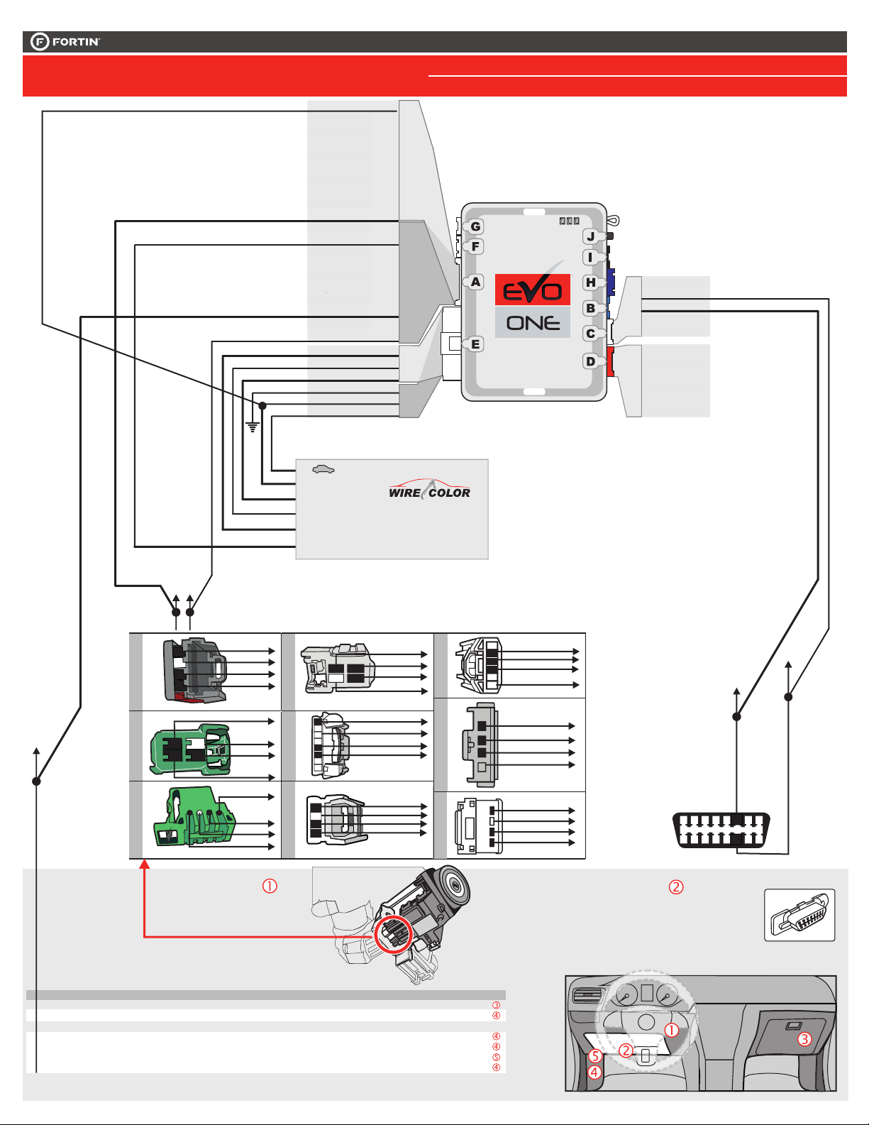
CONNECTION 1
WIRING CONNECTION | SCHÉMA DE BRANCHEMENT
(+) Ignion
(+/-) RX
(-) Parking
Analog Door Lock
(+/-) TX
(+) ParkingLight
(+) Accessory
(+) 12V
Ground
(+) Ignion
(+) Start
Yellow
Purple
Purple/White
Green
White
Orange
Orange/Black
Dk.Blue
Red/Blue
Lt.Blue/Black
Black
Pink
Yellow/Black
Brown/White
Pink/Black
Purple/Yellow
Green/White
Green/Red
White/Black
Lt.Blue
White
Orange
Red
Black
Pink
Yellow
In/ Out A10
In /Out A16
In /Out A17
In /Out A18
In /Out A20
In/ Out E5
In A1
Out A2
Out A3
Out A4
Out A5
Out A6
Out A7
Out A8
In A9
In A11
Out A12
Out A13
In A14
In A15
Out A19
Out E1
Out E2
In E3
In E4
Out E6
Page 2 / 10
1KEY PROGRAMMING DCRYPTOR REQUIRED: PROGRAM. 2
2KEY PROGRAMMING : PROGRAM. 1
C5
Brown
C4
Gray/Black
C3
Gray
C2
Orange/Brown
C1
Orange/Green
D6
White/Red
D5
White/Blue
D4
White/Green
D3
Yellow/Red
D2
Yellow/Blue
D1
Yellow/Green
CAN LOW
CAN HIGH
TXRX
A
BACK VIEW
VUE DE DOS
12
3
4
B
3
VUE DE DOS
4
BACK VIEW
C
1
BACK VIEW
VUE DE DOS
At ignition barrel
Transponder connector
Au barillet d'ignition
Vue de dos
For transpondeur Key Bypass
Pour le contournement du transpondeur
RX and TX of the module
RX et TX du module
Ignition
Ground
TX
RX
RX
Ground
1
Ignition
2
TX
RX
2
4
3
TX
Ground
Ignition
To Vehicle Ignition
Switch & more.
Au Commutateur
d'Ignition & plus du véhicule.
D
4
1 2
BACK VIEW
VUE DE DOS
3
E
BACK VIEW
VUE DE DOS
1 2 3 4 5 6 7 8
F
12
3
4
BACK VIEW
VUE DE DOS
see voir
Ignition
TX
RX
Ground
Ignition
Ground
TX
RX
Ignition
Ground
TX
RX
G
Mazda 2
H
FRONT VIEW
VUE DE FACE
i
FRONT VIEW
VUE DE FACE
ACC ON
LOCK
.com
6
Ignition
5
TX
RX
Ground
1 2 3 4
C3
TX
4
RX
3
Ignition
2
Ground
1
Ignition
Ground
TX
RX
4 3 2 1
START
PUSH
CAN HIGH
Pin 6
1
2 3 4 5 7 8
9
13
10
11 12
OBD-II connector
Front view
Connecteur
C4
CAN LOW
Pin 14
6
6
6
15 16
14
14
OBD-II
Vue de face
MAZDA
2 2011-2012 Dark Green BCM Behind glove box, Gray connector
3 2011-2012 Dark Green BCM Driver Kick Panel, White connector
Axela - 5 Connection not required. | Branchement non requis.
6 - Atenza 2011 Black/White BCM Driver Kick Panel, 16 Pins Connector
2012 Black BCM Driver Kick Panel, 16 Pins Connector
CX-7 2011 Black/White BCM high Driver Kick Panel, Bottom Connector
CX-9 2011 Light Green BCM Driver Kick Panel, 30 Pin Connector
Tribute Connection not required. | Branchement non requis.
YEARS | ANNÉES
Analog Door Lock color
Location
Page 3
This guide may change without notice. See www.fortin.ca for latest version.
Yellow/Green
Yellow/Blue
Yellow/Red
White/Green
White/Blue
White/Red
Orange/Green
Orange/Brown
Brown
White/Black
Purple/Yellow
Pink/Black
Brown/White
Yellow/Black
Pink
Black
Red/Blue
Dk.Blue
Orange/Black
Orange
White
Green
Purple/White
Purple
Ce guide peut faire l’objet de changement sans préavis. Voir www.fortin.ca pour la récente version.
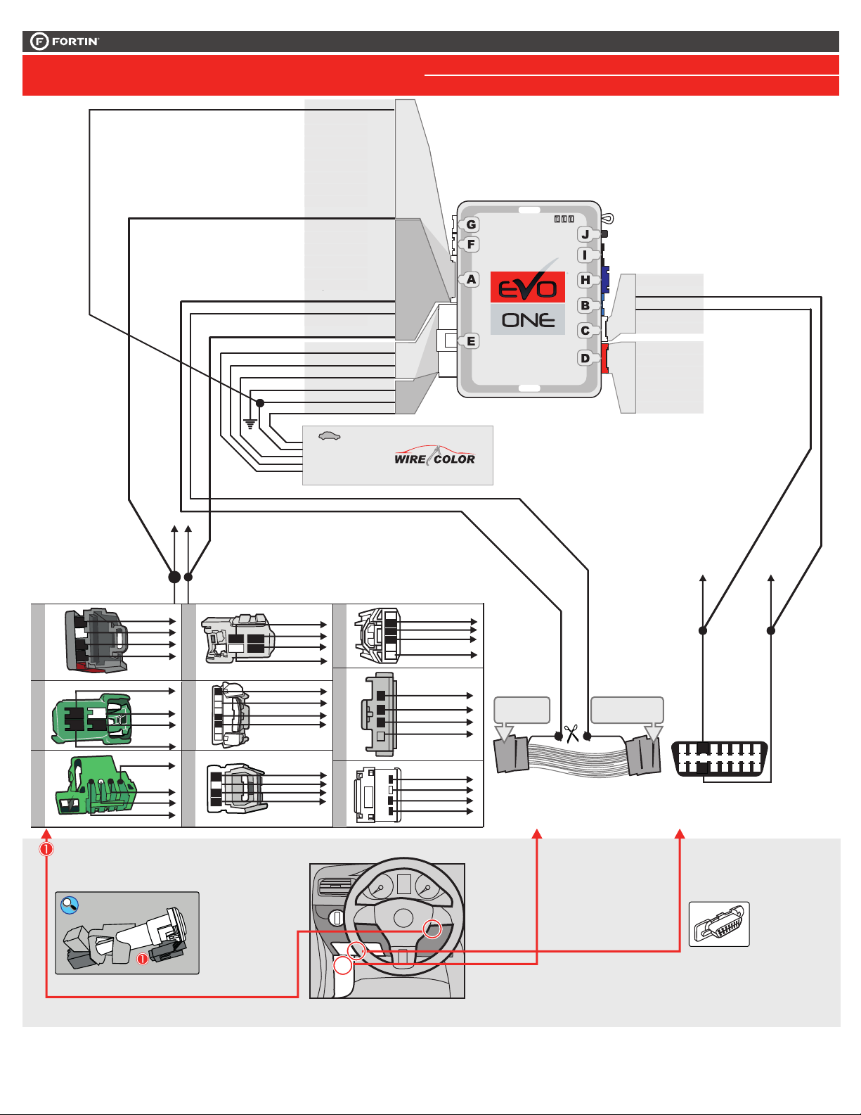
CONNECTION 2
MAZDA TRIBUTE
(+/-) RX
From Skim
To BCM
(+/-) TX
(+) ParkingLight
(+) Accessory
(+) 12V
Ground
(+) Ignion
(+) Start
Yellow
Purple
Purple/White
Green
White
Orange
Orange/Black
Dk.Blue
Red/Blue
Lt.Blue/Black
Black
Pink
Yellow/Black
Brown/White
Pink/Black
Purple/Yellow
Green/White
Green/Red
White/Black
Lt.Blue
White
Orange
Red
Black
Pink
Yellow
In A1
Out A2
Out A3
Out A4
Out A5
Out A6
Out A7
Out A8
In A9
In/ Out A10
In A11
Out A12
Out A13
In A14
In A15
In /Out A16
In /Out A17
In /Out A18
Out A19
In /Out A20
Out E1
Out E2
In E3
In E4
In/ Out E5
Out E6
Page 3 / 10
1KEY PROGRAMMING DCRYPTOR REQUIRED: PROGRAM. 2
2KEY PROGRAMMING : PROGRAM. 1
C5
Brown
C4
Gray/Black
C3
Gray
C2
Orange/Brown
C1
Orange/Green
D6
White/Red
D5
White/Blue
D4
White/Green
D3
Yellow/Red
D2
Yellow/Blue
D1
Yellow/Green
CAN LOW
CAN HIGH
A
BACK VIEW
VUE DE DOS
B
BACK VIEW
VUE DE DOS
C
BACK VIEW
VUE DE DOS
see voir
.com
C3
C4
A10
A20
To Vehicle Ignition
Switch & more.
Au Commutateur
d'Ignition & plus du véhicule.
TXRX
12
3
4
3
4
1
Ignition
Ground
TX
RX
RX
Ground
1
Ignition
2
TX
RX
2
4
3
TX
Ground
Ignition
D
BACK VIEW
VUE DE DOS
E
BACK VIEW
VUE DE DOS
F
BACK VIEW
VUE DE DOS
Ignition
TX
4
1 2
1 2 3 4 5 6 7 8
12
3
4
RX
3
Ground
Ignition
Ground
TX
RX
Ignition
Ground
TX
RX
G
Mazda 2
H
FRONT VIEW
VUE DE FACE
i
FRONT VIEW
VUE DE FACE
4
3
2
1
1
2
3
4
6
5
1 2 3 4
Ignition
TX
RX
Ground
TX
RX
Ignition
Ground
Ignition
Ground
TX
RX
Door side
Côté Porte
A17
Driver door trigger
Pin porte chauffeur
RAP Control
Vehicle side
Côté véhicule
CUT
A18
CAN
HIGH
Pin 3
Gray/Orange
Gris/Orange
1
2 3 4 5 7 8
3
10
11 12 13 14 15 16
9
11
6
6
CAN
LOW
Pin 11
Violet/Orange
At ignition barrel
Transponder connector
Au barillet d'ignition
Vue de dos
Ignition barrel
Barillet de l'ignition
Driver Kick Panel
Harness
Harnais Panneau Latéral
Côté Chauffeur
OBD-II connector
Front view
Connecteur
OBD-II
Vue de face
Page 4
This guide may change without notice. See www.fortin.ca for latest version.
KIA RIO - PUSH-TO-START
This Guide may change without notice. www.ifar.ca for latest version.
Ce Guide peut faire l'objet de changement sans préavis. www.ifar.ca pour la récente version.
Page 4 / 6
PROGRAMMING PROCEDURE 1/2 | PROCÉDURE DE PROGRAMMATION 1/2
REMOTE STARTER / ALARM VERIFICATION PROCEDURE.| PROCÉDURE DE VÉRIFICATION DU DÉMARREUR À DISTANCE / ALARME.
If the vehicle does
not remote-start, or it
does not continue
running: go back to
step 6.
Si le véhicule ne
démarre pas à
distance ou ne
functionne pas,
vérifiez les
branchements et
retournez à l'étape 6
Test the remote-car-
starter keyless-entry
functionality.
Testez les fonctions
verrouillage,
déverrouillage et
autres fonctions du
démarreur à distance.
Adjust the remote-car-
starters tachometer
setting (if required).
Ajustement du
Tachymêtre du
démarreur à distance
(si nécessaire)
TACH
SETTING
6
RELEASE
x1
HOLD
A
E
F
G
J
I
H
B
C
D
A
E
F
G
J
I
H
B
C
D
Release the programming
button when the BLUE LED is
ON.
If the BLUE LED is not ON solid
disconnect the 6-Pin Main
connector and go back to step 1.
ON
Insert the required remaining
connectors.
1
2
3
4
BLUE
BLEU
LOCK
ACC ON
PUSH
START
IGN
Turn the Ignition to the
ON/RUN position.
5
Turn the Ignition to the OFF
position.
LOCK
ACC ON
PUSH
START
OFF
Press and hold the
programming button:
Insert the 6-Pin Main connector.
Insérez les connecteurs requis
restants.
Tournez la clé en position
ignition (ON).
Tournez la clé à OFF.
Appuyez et maintenir le
bouton de programmation
enfoncé:
Insérez le connecteur
Principal à 6-broches.
Relâchez le bouton de
programmation quand la DEL
BLEUE est allumée.
Si le DEL n'est pas BLEU
débranchez le connecteur 6
pins (Connecteur principal) et
allez au début de l'étape 1.
The LEDs will alternate
between BLUE, RED, YELLOW
& BLUE/RED flashes.
Les DELS alterneront entre
un clignotement BLEU,
ROUGE, JAUNE &
BLEU/ROUGE.
The BLUE LED will flash
rapidly.
La DEL BLEU clignotera
rapidement.
The BLUE LED will turn off.
La DEL BLEU s'éteint.
TURN
ON/RUN
TURN
OFF
EVO-ONE PROGRAMMING PROCEDURE | PROCÉDURE DE PROGRAMMATION DU EVO-ONE.
A
E
F
G
J
I
H
B
C
D
A
E
F
G
J
I
H
B
C
D
A
E
F
G
J
I
H
B
C
D
A
E
F
G
J
I
H
B
C
D
A
E
F
G
J
I
H
B
C
D
A
E
F
G
J
I
H
B
C
D
IGNITION ON
ON
IGNITION OFF
FLASH
RAPIDLY
A
E
F
G
J
I
H
B
C
D
IGNITION ON IGNITION OFF
OFF
Place the key in front
the ignition barrel.
Placez la clé devant
le barrilet d'ignition.
The remote starter
must be able to start
the vehicle.
Le démarreur à
distance doit pouvoir
démarrer le véhicule.
LOCK
ACC ON
START
IGN
ON
PUSH
LOCK
ACC ON
PUSH
START
PUSH
START
PUSH
ST
ART
PUSH
START
PUSH
START
KIA RIO - PUSH-TO-START
This Guide may change without notice. www.ifar.ca for latest version.
Ce Guide peut faire l'objet de changement sans préavis. www.ifar.ca pour la récente version.
Page 4 / 6
PROGRAMMING PROCEDURE 1/2 | PROCÉDURE DE PROGRAMMATION 1/2
A
E
F
G
J
I
H
B
C
D
A
E
F
G
J
I
H
B
C
D
EVO-ONE PROGRAMMING PROCEDURE | PROCÉDURE DE PROGRAMMATION DU EVO-ONE.
CETTE PROGRAMMATION EST POUR LES
FORD / MAZDA
A
E
F
G
J
I
H
B
C
D
A
E
F
G
J
I
H
B
C
D
A
E
F
G
J
I
H
B
C
D
A
E
F
G
J
I
H
B
C
D
A
E
F
G
J
I
H
B
C
D
A
E
F
G
J
I
H
B
C
D
A
E
F
G
J
I
H
B
C
D
A
E
F
G
J
I
H
B
C
D
PROGRAMMING PROCEDURE | PROCÉDURE DE PROGRAMMATION
LOCK
ACC ON
PUSH
START
IGN
TURN
ON/RUN
9
KEY#1
CLÉ#1
Turn the Ignition to the
ON/RUN position.
Tournez la clé en position
ignition (ON).
Les DELs ROUGE et BLEU
clignoteront dix (10) fois
rapidement.
Key bypass programmed.
Les DELs ROUGE et BLEU
clignoteront dix (10) fois
rapidement. Contournement de
clé programmé.
Turn the Ignition to the OFF
position.
LOCK
ACC ON
PUSH
START
OFF
Tournez la clé à OFF.
The BLUE LED will turn off.
La DEL BLEU s'éteint.
TURN
OFF
The module is now
programmed.
Le module est
programmé.
Use the remote of the remote
starter or security system to test
all of the supported features to
ensure proper programming.
Testez toutes les fonctions
supportées sur le véhicule avec la
télécommande du démarreur à
distance ou du système de sécurité.
The BLUE LED will flash
rapidly.
CAN-Bus programmed.
La DEL BLEU clignotera
rapidement:
Réseau CAN programmé.
Wait Attendre
8
CETTE PROGRAMMATION EST POUR LES
FORD / MAZDA
FLASH 10X
IGNITION ON
FLASH 10X
FLASH
A
E
F
G
J
I
H
B
C
D
IGNITION ON IGNITION OFF
OFF
Remove all keys from key remote cards.
Keep all cards at least 3 meters (10 feet)
away from the vehicle to proceed.
Retirez les 2 clés des télécommandes.
(cartes).
Éloignez les télécommandes du véhicule
(10 pieds / 3 mètres minimum) pour
procéder à la programmation.
10’
If the vehicle equipped with SMART KEY:
Si le véhicule est équipé d'une clé INTELLIGENTE:
Make sure to have two valide vehicle key.
Assurez-vous d'avoir deux clés valides du
véhicule.
Make sure to have one valide vehicle key.
Assurez-vous d'avoir une clé valide du
véhicule.
FLASH 10X
Ce guide peut faire l’objet de changement sans préavis. Voir www.fortin.ca pour la récente version.
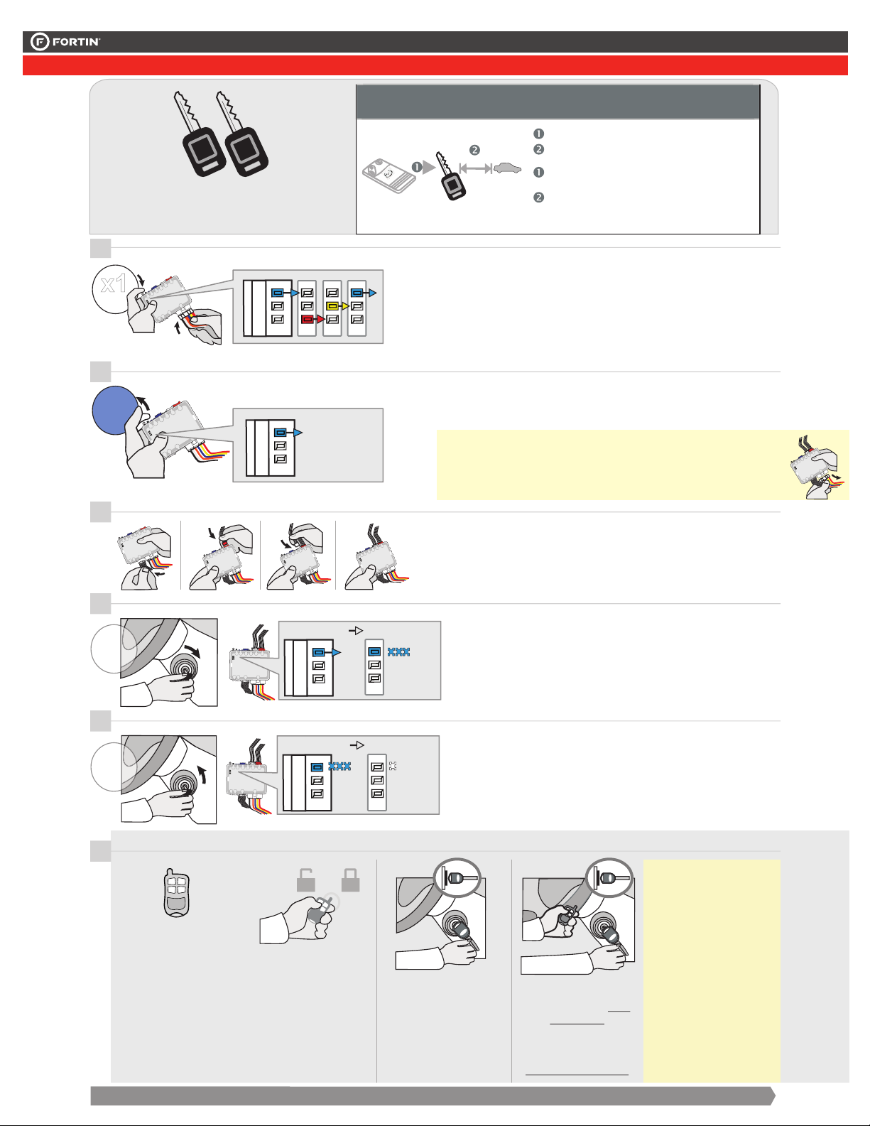
KEY BYPASS PROGRAMMING PROCEDURE 1/3 | PROCÉDURE DE PROGRAMMATION CONTOURNEMENT DE CLÉ 1/3
If the vehicle equipped with SMART KEY:
Si le véhicule est équipé d'une clé INTELLIGENTE:
Make sure to have two valide vehicle key.
Assurez-vous d'avoir deux clés valides du
véhicule.
1
x1
HOLD
2
RELEASE
BLUE
ON
BLEU
3
4
TURN
ON/RUN
LOCK
ACC ON
PUSH
IGNITION OFF
IGN
START
IGNITION ON
ON
FLASH
RAPIDLY
10’
Remove all keys from key remote cards.
Keep all cards at least 3 meters (10 feet)
away from the vehicle to proceed.
Retirez les 2 clés des télécommandes.
(cartes).
Éloignez les télécommandes du véhicule
(10 pieds / 3 mètres minimum) pour
procéder à la programmation.
Press and hold the
programming button:
Insert the 6-Pin Main connector.
The LEDs will alternate
between BLUE, RED, YELLOW
& BLUE/RED flashes.
Release the programming
button when the BLUE LED is
ON.
If the BLUE LED is not ON solid
disconnect the 6-Pin Main
connector and go back to step 1.
Insert the required remaining
connectors.
Turn the Ignition to the
ON/RUN position.
The BLUE LED will flash
rapidly.
Appuyez et maintenir le
bouton de programmation
enfoncé:
Insérez le connecteur
Principal à 6-broches.
Les DELS alterneront entre
un clignotement BLEU,
ROUGE, JAUNE &
BLEU/ROUGE.
Relâchez le bouton de
programmation quand la DEL
BLEUE est allumée.
Si le DEL n'est pas BLEU
débranchez le connecteur 6
pins (Connecteur principal) et
allez au début de l'étape 1.
Insérez les connecteurs requis
restants.
Tournez la clé en position
ignition (ON).
La DEL BLEU clignotera
rapidement.
Page 4 / 10
5
TURN
OFF
LOCK
OFF
ACC ON
PUSH
START
REMOTE STARTER / ALARM VERIFICATION PROCEDURE.| PROCÉDURE DE VÉRIFICATION DU DÉMARREUR À DISTANCE / ALARME.
6
TACH
SETTING
Adjust the remote-car-
starters tachometer
setting (if required).
Ajustement du
Tachymêtre du
démarreur à distance
(si nécessaire)
IGNITION ON IGNITION OFF
Test the remote-car-
starter keyless-entry
functionality.
Testez les fonctions
verrouillage,
déverrouillage et
autres fonctions du
démarreur à distance.
CONTINUED NEXT PAGE | CONTINUEZ À LA PAGE SUIVANTE
OFF
Turn the Ignition to the OFF
position.
The BLUE LED will turn off.
START
PUSH
ACC ON
START
LOCK
START
PUSH
PUSH
Place the key in front
the ignition barrel.
Placez la clé devant
le barrilet d'ignition.
Tournez la clé à OFF.
La DEL BLEU s'éteint.
START
PUSH
IGN
ON
ACC ON
START
LOCK
ST
PUSH
ART
PUSH
The remote starter
must be able to start
the vehicle.
If the vehicle does
not remote-start, or it
does not continue
running: go back to
step 6.
Si le véhicule ne
démarre pas à
distance ou ne
functionne pas,
vérifiez les
Le démarreur à
distance doit pouvoir
branchements et
retournez à l'étape 6
démarrer le véhicule.
Page 5
This guide may change without notice. See www.fortin.ca for latest version.
PROGRAMMING PROCEDURE | PROCÉDURE DE PROGRAMMATION
A
E
F
G
J
I
H
B
C
D
A
E
F
G
J
I
H
B
C
D
A
E
F
G
J
I
H
B
C
D
A
E
F
G
J
I
H
B
C
D
A
E
F
G
J
I
H
B
C
D
A
E
F
G
J
I
H
B
C
D
A
E
F
G
J
I
H
B
C
D
Ce guide peut faire l’objet de changement sans préavis. Voir www.fortin.ca pour la récente version.
KEY BYPASS PROGRAMMING PROCEDURE 2/3 | PROCÉDURE DE PROGRAMMATION CONTOURNEMENT DE CLÉ 2/3
TRANSPONDER PROGRAMMING PROCEDURE | PROCÉDURE DE PROGRAMMATION DU TRANSPONDEUR
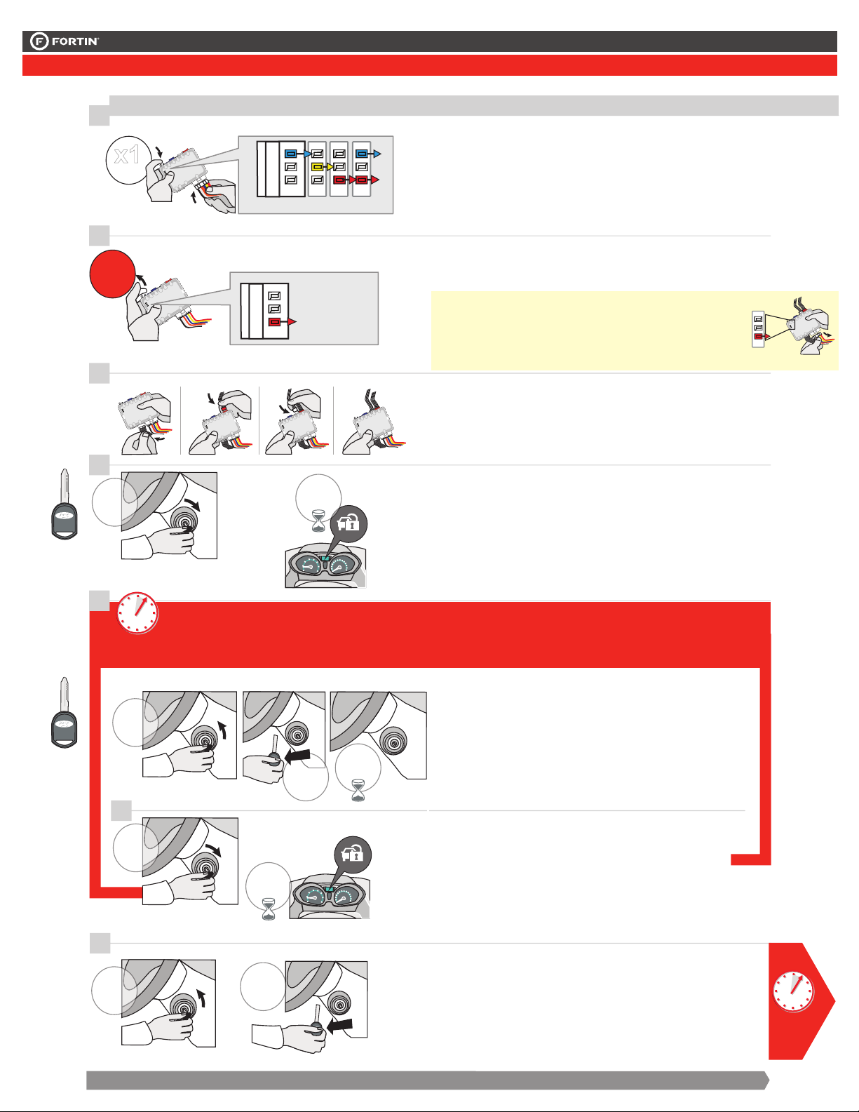
7
x1
HOLD
Press and hold the
programming button:
Insert the 6-Pin Main connector.
Appuyez et maintenir le
bouton de programmation
enfoncé:
Insérez le connecteur
Page 5 / 10
Principal à 6-broches.
8
RELEASE
LED may differ depending on the module casing.
L’apparence des DELS peut différer selon le boîtier du module.
The LEDs will alternate
between BLUE, RED, YELLOW
& BLUE/RED flashes.
Release the programming
button when the LED is RED.
Les DELS alterneront entre
un clignotement BLEU,
ROUGE, JAUNE &
BLEU/ROUGE.
Relâchez le bouton de
programmation quand la DEL
est ROUGE.
KEY#1
CLÉ#1
KEY#2
CLÉ#2
9
10
TURN
ON/RUN
11
5 sec. max
TURN
12
TURN
ON/RUN
13
OFF
ON
RED
ROUGE
If the LED is not solid RED
disconnect the 6 Pin
connector (Main-Harness)
and go back to step 1.
Insert the required remaining
connectors.
WAIT
ACC ON
IGN
START
LOCK
PUSH
3 SEC.
Turn the first functIonal key to
the ON/RUN position.
Wait 3 seconds or until the
security light turns OFF.
Si le DEL n'est pas ROUGE
solide débranchez le
connecteur 6 pins
(Connecteur principal) et allez
à l'étape 1.
Insérez les connecteurs requis
restants.
Tournez la première clé
fonctionnelle à la position
ON/RUN.
Attendre 3 secondes ou
jusqu'à ce que la lumière
sécurité du tableau de bord
s’éteigne.
CAUTION The following step must be completed within 5 seconds.Otherwise disconnect all connectors and go
back to step 1.
ATTENTION les prochaines étapes doivent être complétées en moins de 5 secondes. Si non, débranchez tous les
connecteurs et allez à l'étape 1.
Tournez la clé à la
position ARRÊT
(OFF)
et retirez la clé du
barillet.
Tournez la
deuxième clé
fonctionnelle à la
position ON/RUN.
Attendre 3 secondes ou
jusqu'à ce que la lumière
sécurité du tableau de bord
LOCK
ACC ON
PUSH
ACC ON
LOCK
PUSH
OFF
START
START
IGN
WAIT
3 SEC.
PUSHPUSH
REMOVE
ACC ON
LOCK
KEY
Turn the ignition to
the OFF position
START
ACC ON
START
LOCK
and remove the first
WAIT
3 SEC.
key.
Wait 3 seconds. Attendre 3 secondes.
Turn the second
functIonal key to
the ON/RUN
position.
Wait 3 seconds or until the
security light turns OFF.
s’éteigne.
TURN
OFF
LOCK
ACC ON
PUSH
OFF
START
REMOVE
KEY
ACC ON
START
LOCK
PUSHPUSH
CONTINUED NEXT PAGE | CONTINUEZ À LA PAGE SUIVANTE
Turn the ignition to the OFF
position
and remove the second key.
Tournez la clé à la
position ARRÊT (OFF)
et retirez la clé du
barillet.
5 sec.
max
Page 6
This guide may change without notice. See www.fortin.ca for latest version.
A
E
F
G
J
I
H
B
C
D
PROGRAMMING PROCEDURE | PROCÉDURE DE PROGRAMMATION
A
E
F
G
J
I
H
B
C
D
A
E
F
G
J
I
H
B
C
D
EVO-ONE
Ce guide peut faire l’objet de changement sans préavis. Voir www.fortin.ca pour la récente version.
KEY BYPASS PROGRAMMING PROCEDURE 3/3 | PROCÉDURE DE PROGRAMMATION CONTOURNEMENT DE CLÉ 3/3
Page 6 / 10
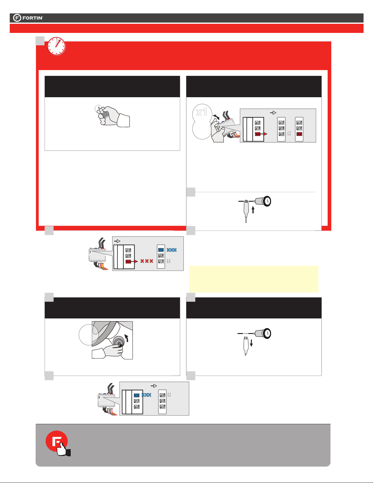
14
CAUTION The following step must be completed within 5 seconds.Otherwise disconnect all connectors and go
back to step 1.
5 sec. max
ATTENTION les prochaines étapes doivent être complétées en moins de 5 secondes. Si non, débranchez tous les
connecteurs et allez à l'étape 1.
AUTOMATIC TRANSMISSION
Activate the remote
starter.
15
AUTOMATIQUETRANSMISSION
x1
PRESS
CONTINUED NEXT PAGE | CONTINUEZ À LA PAGE SUIVANTE
Actionnez le démarreur à
distance.
RELEASE
Press and hold the
programming button until
the LED flashes once
than release the
programming button.
The RED LED will
flash once (1x).
15
Using a jumper
wire, apply power
(12v) to the
vehicle's ignition1.
Ignition1
MANUELLETRANSMISSION
PRESS X1
ON
Pesez et garder appuyé le
bouton de programmation
jusqu'à se que le DEL
clignote une fois et
relâcher le bouton.
La DEL ROUGE
clignote 1 fois.
À l’aide d’un fil
(jumper) appliquez
12V
12v sur l’ignition1
du véhicule.
16
MANUAL TRANSMISSION
FLASH 10X
FLASH
10X
Flash
OFF
The RED LED will flash
rapidly ten (10) times and
after the BLUE LED will
flash rapidly.
If the LED is solid RED
disconnect the 6 Pin
connector (Main-Harness) and
go back to step 1.
La DEL ROUGE clignotera
dix (10) fois rapidement et
le ensuite DEL BLEU
clignotera rapidement.
Si le DEL est ROUGE solide
débranchez le connecteur 6
pins (Connecteur principal) et
allez à l'étape 1.
FLASH X1
ON
16
AUTOMATIC TRANSMISSION
AUTOMATIQUETRANSMISSION
TURN
OFF
LOCK
PUSH
OFF
ACC ON
START
17
MANUAL TRANSMISSION
MANUELLETRANSMISSION
Ignition
Remove the jumper. Retirez le fil (jumper).
Turn the Ignition to the OFF
Tournez la clé à OFF.
position.
17 18
IGNITION ON IGNITION OFF
OFF
The BLUE LED will turn off.
La DEL BLEU s'éteint.
Manual transmission:
Remove the jumper.
Transmission manuelle:
Retirez le fil (jumper).
The module is now
programmed.
Use the remote of the remote
starter or security system to test
all of the supported features to
ensure proper programming.
Le module est
programmé.
Testez toutes les fonctions
supportées sur le véhicule avec la
télécommande du démarreur à
distance ou du système de sécurité.
Page 7
This guide may change without notice. See www.fortin.ca for latest version.
PROGRAMMING PROCEDURE WITH DCRYPTOR 1/3 | PROCÉDURE DE PROGRAMMATION AVEC DCRYPTOR 1/3
CETTE PROGRAMMATION EST POUR LES
MAZDA / FORD
REMOTE STARTER / ALARM VERIFICATION PROCEDURE.| PROCÉDURE DE VÉRIFICATION DU DÉMARREUR À DISTANCE / ALARME.
If the vehicle does
not remote-start, or it
does not continue
running: go back to
step 6.
Si le véhicule ne
démarre pas à
distance ou ne
fonctionne pas,
vérifiez les
branchements et
retournez à l'étape 6
Test the remote-car-
starter and keyless-
entry functionality.
Testez les fonctions
verrouillage,
déverrouillage et
autres fonctions du
démarreur à distance.
Adjust the remote-car-
starters tachometer
setting (if required).
Ajustement du
Tachymêtre du
démarreur à distance
(si nécessaire)
TACH
SETTING
6
Place the key in front
the ignition barrel.
Placez la clé devant
le barrilet d'ignition.
The remote starter
must be able to start
the vehicle.
Le démarreur à
distance doit pouvoir
démarrer le véhicule.
LOCK
ACC ON
START
IGN
ON
PUSH
LOCK
ACC ON
PUSH
START
PUSH
START
PUSH
ST
ART
PUSH
START
PUSH
START
PROGRAMMING PROCEDURE WITH DCRYPTOR 1/3 | PROCÉDURE DE PROGRAMMATION AVEC DCRYPTOR 1/3
EVO-ONE PROGRAMMING PROCEDURE | PROCÉDURE DE PROGRAMMATION DU EVO-ONE.
Release the programming
button when the BLUE LED is
ON.
If the BLUE LED is not ON solid
disconnect the 6-Pin Main
connector and go back to step 1.
Insert the required remaining
connectors.
2
3
Press and hold the
programming button:
Insert the 6-Pin Main connector.
Insérez les connecteurs requis
restants.
Appuyez et maintenir le
bouton de programmation
enfoncé:
Insérez le connecteur
Principal à 6-broches.
Relâchez le bouton de
programmation quand la DEL
BLEUE est allumée.
Si la DEL BLEUE n'est pas
allumée débranchez le
connecteur Principal à 6-
broches et retournez au début
de l'étape 1.
The LEDs will alternate
between BLUE, RED, YELLOW
& BLUE/RED flashes.
Les DELS alterneront entre
un clignotement BLEU,
ROUGE, JAUNE &
BLEU/ROUGE.
5
The BLUE LED will flash
rapidly.
La DEL BLEU clignote
rapidement.
The BLUE LED will turn off.
La DEL BLEU s'éteint.
1
Turn the Ignition to the
OFF position.
Tournez la clé à OFF.
4
LOCK
ACC ON
PUSH
START
IGN
LOCK
ACC ON
PUSH
START
OFF
Tournez la clé en position
ignition (ON).
Turn the Ignition to the
ON/RUN position.
CONTINUED NEXT PAGE | CONTINUEZ À LA PAGE SUIVANTE
Parts required (not included)
Pièces requises (non incluses)
1x ,
1x software
1x
Microsoft Windows Computer with
Internet connection
FLASH LINK UPDATER
FLASH LINK 2MANAGER
1x ,
1x Programme
1x
Ordinateur Microsoft Windows avec
connection Internet
FLASH LINK UPDATER
FLASH LINK 2MANAGER
x1
HOLD
A
E
F
G
J
I
H
B
C
D
LED may differ depending on the module casing.
L’apparence des DELS peut différer selon le boîtier du module.
RELEASE
A
E
F
G
J
I
H
B
C
D
ON
BLUE
BLEU
A
E
F
G
J
I
H
B
C
D
A
E
F
G
J
I
H
B
C
D
A
E
F
G
J
I
H
B
C
D
A
E
F
G
J
I
H
B
C
D
A
E
F
G
J
I
H
B
C
D
IGNITION ON
ON
IGNITION OFF
FLASH
RAPIDLY
A
E
F
G
J
I
H
B
C
D
IGNITION ON IGNITION OFF
OFF
A
E
F
G
J
I
H
B
C
D
A
E
F
G
J
I
H
B
C
D
PROGRAMMING PROCEDURE | PROCÉDURE DE PROGRAMMATION
LOCK
ACC ON
PUSH
START
IGN
TURN
ON/RUN
9
KEY#1
CLÉ#1
Turn the Ignition to the
ON/RUN position.
Tournez la clé en position
ignition (ON).
Les DELs ROUGE et BLEU
clignoteront dix (10) fois
rapidement.
Key bypass programmed.
Les DELs ROUGE et BLEU
clignoteront dix (10) fois
rapidement. Contournement de
clé programmé.
Turn the Ignition to the OFF
position.
LOCK
ACC ON
PUSH
START
OFF
Tournez la clé à OFF.
The BLUE LED will turn off.
La DEL BLEU s'éteint.
TURN
OFF
The module is now
programmed.
Le module est
programmé.
Use the remote of the remote
starter or security system to test
all of the supported features to
ensure proper programming.
Testez toutes les fonctions
supportées sur le véhicule avec la
télécommande du démarreur à
distance ou du système de sécurité.
The BLUE LED will flash
rapidly.
CAN-Bus programmed.
La DEL BLEU clignotera
rapidement:
Réseau CAN programmé.
Wait Attendre
8
FLASH 10X
IGNITION ON
FLASH 10X
FLASH
A
E
F
G
J
I
H
B
C
D
IGNITION ON IGNITION OFF
OFF
Remove all keys from key remote cards.
Keep all cards at least 3 meters (10 feet)
away from the vehicle to proceed.
Retirez les 2 clés des télécommandes.
(cartes).
Éloignez les télécommandes du véhicule
(10 pieds / 3 mètres minimum) pour
procéder à la programmation.
10’
If the vehicle equipped with SMART KEY:
Si le véhicule est équipé d'une clé INTELLIGENTE:
Remove all keys from key remote cards.
Keep all cards at least 3 meters (10 feet)
away from the vehicle to proceed.
Retirez les 2 clés des télécommandes.
(cartes).
Éloignez les télécommandes du véhicule
(10 pieds / 3 mètres minimum) pour
procéder à la programmation.
10’
If the vehicle equipped with SMART KEY:
Si le véhicule est équipé d'une clé INTELLIGENTE:
Make sure to have two valide vehicle key.
Assurez-vous d'avoir deux clés valides du
véhicule.
Make sure to have two valide vehicle key.
Assurez-vous d'avoir deux clés valides du
véhicule.
Make sure to have one valide vehicle key.
Assurez-vous d'avoir une clé valide du
véhicule.
FLASH 10X
A
E
F
G
J
I
H
B
C
D
LOCK
ACC ON
PUSH
START
IGN
TURN
ON/RUN
Turn the Ignition to the
ON/RUN position.
Tournez la clé en position
ignition (ON).
Les DELs ROUGE et BLEU
clignoteront dix (10) fois
rapidement.
Key bypass programmed.
Les DELs ROUGE et BLEU
clignoteront dix (10) fois
rapidement. Contournement de
clé programmé.
Turn the Ignition to the OFF
position.
LOCK
ACC ON
PUSH
START
OFF
Tournez la clé à OFF.
The BLUE LED will turn off.
La DEL BLEU s'éteint.
TURN
OFF
The module is now
programmed.
Le module est
programmé.
Use the remote of the remote
starter or security system to test
all of the supported features to
ensure proper programming.
Testez toutes les fonctions
supportées sur le véhicule avec la
télécommande du démarreur à
distance ou du système de sécurité.
The BLUE LED will flash
rapidly.
CAN-Bus programmed.
La DEL BLEU clignotera
rapidement:
Réseau CAN programmé.
Wait Attendre
CETTE PROGRAMMATION EST POUR LES
FORD / MAZDA
FLASH 10X
IGNITION ON
FLASH 10X
FLASH
A
E
F
G
J
I
H
B
C
D
IGNITION ON IGNITION OFF
OFF
véhicule.
FLASH 10X
Disconnect the 6-Pin (Main-
Harness) connector
and after all the remaining
connector.
7
Débranchez le connecteur 6-
pins (Connecteur principal) et
après tous les connecteurs du
EVO-ALL.
PROGRAMMING PROCEDURE WITH DCRYPTOR 2/3 | PROCÉDURE DE PROGRAMMATION AVEC DCRYPTOR 2/3
on.
A
E
F
G
J
I
H
B
C
D
A
E
F
G
J
I
H
B
C
D
A
E
F
G
J
I
H
B
C
D
A
E
F
G
J
I
H
B
C
D
A
E
F
G
J
I
H
B
C
D
A
E
F
G
J
I
H
B
C
D
A
E
F
G
J
I
H
B
C
D
A
E
F
G
J
I
H
B
C
D
A
E
F
G
J
I
H
B
C
D
A
E
F
G
J
I
H
B
C
D
A
E
F
G
J
I
H
B
C
D
A
E
F
G
J
I
H
B
C
D
A
E
F
G
J
I
H
B
C
D
Ce guide peut faire l’objet de changement sans préavis. Voir www.fortin.ca pour la récente version.
PROGRAM. 2 CONTINUED NEXT PAGE | SUITE À LA PAGE SUIVANTE 1/2
Page 7 / 10
If the vehicle equipped with SMART KEY:
Si le véhicule est équipé d'une clé INTELLIGENTE:
Make sure to have one valide vehicle key.
Make sure to have two valide vehicle key.
Assurez-vous d'avoir une clé valide du
Assurez-vous d'avoir deux clés valides du
véhicule.
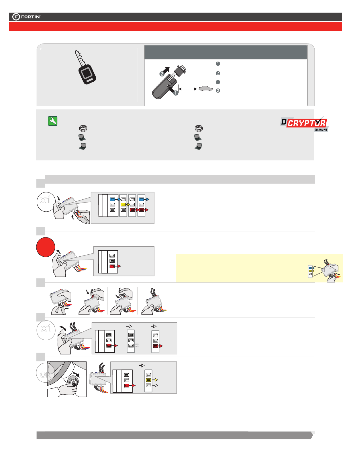
Parts required (not included)
10'
Pièces requises (non incluses)
Remove the valet key from the back of the
OEM remote.
Keep all OEM remotes at least 3 meters (10
feet) away from the vehicle to proceed.
Re tire z l a c lé vale t d u d os de l a
télécommande d'origine.
Éloignez toutes les télécommandes d'origine
du véhicule (10 pieds / 3 mètres min) pour
procéder à la programmation.
FLASH LINK UPDATER
1x ,
FLASH LINK 2MANAGER
1x software
Microsoft Windows Computer with
1x
Internet connection
TRANSPONDER PROGRAMMING PROCEDURE | PROCÉDURE DE PROGRAMMATION DU TRANSPONDEUR
8
1
x1
HOLD
LED may differ depending on the module casing.
L’apparence des DELS peut différer selon le boîtier du module.
2
9
RELEASE
10
3
11
4
x1
PRESS
12
5
IGN
ON
ACC ON
IGN
START
LOCK
PUSH
PRESS X1
ON
IGNITION OFF
RED
ON
ROUGE
OFF
ON
OFF
IGNITION
ON
ON
OFF
ON
ON
1x ,
1x Programme
1x
connection Internet
Press and hold the
programming button:
Insert the 6-Pin Main connector.
Release the programming
button when the LED is RED.
If the LED is not solid RED
disconnect the 6 Pin
connector (Main-Harness)
and go back to step 1.
Insert the required remaining
connectors.
Press and release the
programming button once
(1x).
Turn the Ignition to the
ON/RUN position.
FLASH LINK UPDATER
Ordinateur Microsoft Windows avec
The LEDs will alternate
between BLUE, RED, YELLOW
& BLUE/RED flashes.
The RED LED will flash once.
WAIT the RED LED will turn
OFF.
The YELLOW LED will turn
FLASH LINK 2MANAGER
Appuyez et maintenir le
bouton de programmation
enfoncé:
Insérez le connecteur
Principal à 6-broches.
Les DELS alterneront entre
un clignotement BLEU,
ROUGE, JAUNE &
BLEU/ROUGE.
Relâchez le bouton de
programmation quand la DEL
est ROUGE.
Si le DEL n'est pas ROUGE
solide débranchez le
connecteur 6 pins
(Connecteur principal) et allez
à l'étape 1.
Insérez les connecteurs requis
restants.
Appuyez et relâchez 1 fois le
bouton de programmation.
La DEL ROUGE clignote 1
fois.
Tournez la clé en position
ignition (ON).
ATTENDRE que l a DEL
ROUGE s'éteigne.
La DEL JAUNE s'allume.
Page 8
This guide may change without notice. See www.fortin.ca for latest version.
Disconnect the 6-Pin (Main-
Harness) connector
and after all the remaining
connector.
7
Débranchez le connecteur 6-
pins (Connecteur principal) et
après tous les connecteurs du
EVO-ALL.
PROGRAMMING PROCEDURE WITH DCRYPTOR 2/3 | PROCÉDURE DE PROGRAMMATION AVEC DCRYPTOR 2/3
Release the programming
button when the LED is RED.
If the LED is not solid RED
disconnect the 6 Pin
connector (Main-Harness)
and go back to step 1.
Insert the required remaining
connectors.
8
9
10
11
Press and hold the
programming button:
Insert the 6-Pin Main connector.
Insérez les connecteurs requis
restants.
Appuyez et maintenir le
bouton de programmation
enfoncé:
Insérez le connecteur
Principal à 6-broches.
Relâchez le bouton de
programmation quand la DEL
est ROUGE.
Si le DEL n'est pas ROUGE
solide débranchez le
connecteur 6 pins
(Connecteur principal) et allez
à l'étape 1.
The LEDs will alternate
between BLUE, RED, YELLOW
& BLUE/RED flashes.
Les DELS alterneront entre
un clignotement BLEU,
ROUGE, JAUNE &
BLEU/ROUGE.
Press and release the
programming button once
(1x).
12
x1
PRESS
Appuyez et relâchez 1 fois le
bouton de programmation.
WAIT the RED LED will turn
OFF.
The YELLOW LED will turn
on.
ATTENDRE que l a DEL
ROUGE s'éteigne.
La DEL JAUNE s'allume.
TRANSPONDER PROGRAMMING PROCEDURE | PROCÉDURE DE PROGRAMMATION DU TRANSPONDEUR
The RED LED will flash once.
La DEL ROUGE clignote 1
fois.
Turn the Ignition to the
ON/RUN position.
Tournez la clé en position
ignition (ON).
LOCK
ACC ON
PUSH
START
IGN
ON
IGN
A
E
F
G
J
I
H
B
C
D
A
E
F
G
J
I
H
B
C
D
A
E
F
G
J
I
H
B
C
D
A
E
F
G
J
I
H
B
C
D
RELEASE
A
E
F
G
J
I
H
B
C
D
ON
RED
ROUGE
x1
HOLD
A
E
F
G
J
I
H
B
C
D
LED may differ depending on the module casing.
L’apparence des DELS peut différer selon le boîtier du module.
A
E
F
G
J
I
H
B
C
D
A
E
F
G
J
I
H
B
C
D
A
E
F
G
J
I
H
B
C
D
A
E
F
G
J
I
H
B
C
D
A
E
F
G
J
I
H
B
C
D
OFF
ON
PRESS X1
OFF
ON
ON
A
E
F
G
J
I
H
B
C
D
IGNITION OFF
IGNITION
ON
OFF
ON
ON
A
E
F
G
J
I
H
B
C
D
A
E
F
G
J
I
H
B
C
D
A
E
F
G
J
I
H
B
C
D
Ce guide peut faire l’objet de changement sans préavis. Voir www.fortin.ca pour la récente version.
Page 8 / 10
CONTINUED NEXT PAGE | SUITE À LA PAGE SUIVANTE 2/2
13
6
IGN
OFF
14
7
IGN
ON
15
8
IGN
OFF
9
10
I
J
H
F
G
A
OFF
ACC ON
START
LOCK
PUSH
ACC ON
IGN
START
LOCK
PUSH
OFF
ACC ON
START
LOCK
PUSH
D
C
B
H
I
J
E
A
F
G
D
C
B
H
J
I
E
A
F
G
B
C
D
E
D
C
B
H
I
J
E
A
F
G
FLASH LINK
UPDATER 2
11
C
D
I
J
H
B
F
G
A
E
I
J
J
D
C
B
H
A
F
G
IGNITION ON
IGNITION OFF
D
C
B
H
I
E
A
F
G
E
IGNITION
ON
FLASH RAPIDLY
ON
ON
D
C
B
H
I
J
E
A
F
G
OFF
I
J
I
J
F
G
B
H
F
G
I
J
OFF
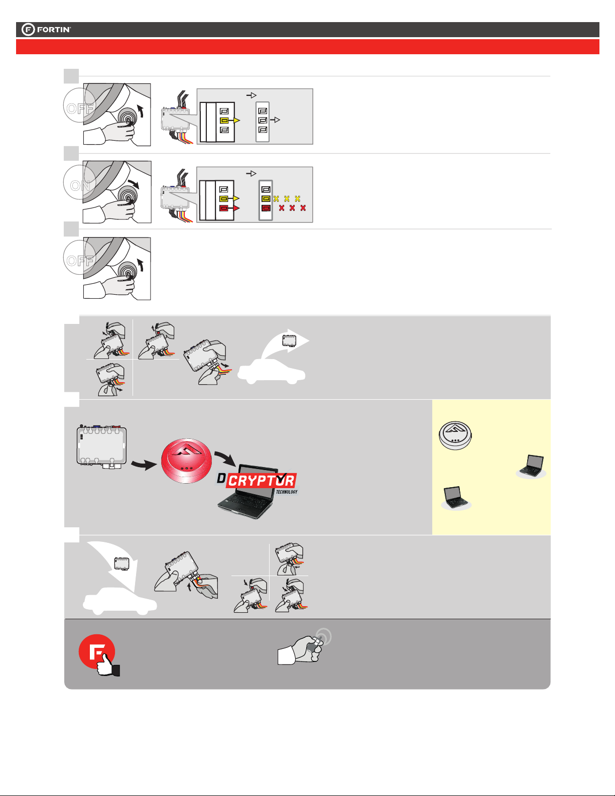
Turn the Ignition to the
OFF position.
WAITthe YELLOW LED will
turn OFF.
Turn the Ignition to the
ON/RUN position.
The RED and YELLOW LEDs
will alternate.
Turn the Ignition to the
OFF position.
C
D
H
B
A
E
Disconnect all connectors and after the 6-Pin (Main-Harness)
connector.
Débranchez tous les connecteurs et ensuite le connecteur
6-pins (Connecteur principal).
Connect the module to the
FLASH LINK UPDATER 2
and visit the DCryptor menu
in the Flash-Link Manager.
Branchez le module au
FLASH LINK UPDATER 2
et visitez le menu DCryptor
dans le Flash-Link Manager.
D
C
E
A
D
C
B
H
E
A
F
G
AFTER DCRYPTOR PROGRAMMING COMPLETED
Go back to the vehicle and reconnect the 6-Pin (Main-
Harness) connector and after all the remaining connector.
APRÈS LA PROCÉDURE DE PROGRAMMATION
DCRYPTOR COMPLETÉE : retournez au véhicule et
rebranchez le connecteur 6-pins (Connecteur principal)
et après tous les connecteurs.
Tournez la clé à OFF.
ATTENDRE que la DEL
JAUNE s'éteigne.
Tournez la clé en position
ignition (ON).
La DEL ROUGE et JAUNE
alternent.
Tournez la clé à OFF.
Parts required (not included)
Pièces requises (non incluses)
FLASH LINK MANAGER
SOFTWARE | PROGRAMME
FLASH LINK
UPDATER 2
Microsoft Windows
Computer with
Internet connection
Ordinateur Microsoft
Windows avec
connection Internet
The module is now programmed.
Le module est programmé.
REMOTE STARTER / ALARM VERIFICATION
PROCEDURE | PROCÉDURE DE VÉRIFICATION
DU DÉMARREUR À DISTANCE / ALARME
Test the remote starter. Remote start the vehicle.
Testez le démarreur à distance. Démarrez le véhicule
à distance.
Page 9
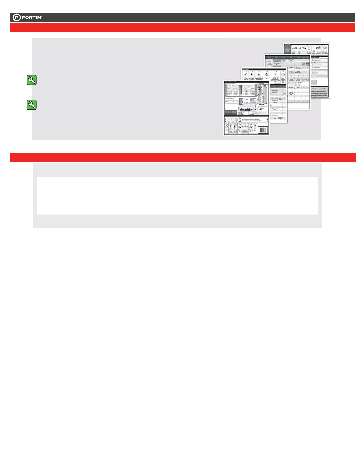
This guide may change without notice. See www.fortin.ca for latest version.
Ce guide peut faire l’objet de changement sans préavis. Voir www.fortin.ca pour la récente version.
Page 9 / 10
REMOTE STARTER PROGRAMMING PROCEDURE | PROCÉDURE DE PROGRAMMATION DU DÉMARREUR À DISTANCE
REFER TO THE QUICK INSTALL GUIDE INCLUDED WITH THE
MODULE FOR THE REMOTE STARTER PROGRAMMING.
RÉFÉREZ-VOUS AU GUIDE D’INSTALLATION RAPIDE INCLUS
AVEC LE MODULE POUR LA PROGRAMMATION DU DÉMARREUR
À DISTANCE.
VEHICLE EQUIPPED WITH OEM ALARM | VÉHICULE ÉQUIPPÉS D’UNE ALARME D’ORIGINE
Some vehicles must be UNLOCKED to disarm the OEM alarm
before remote start. Enable option D2 using the FlashLink
Manager. When this option is enabled the module will
automatically UNLOCK before remote start and LOCK after
the vehicle has remote started.
Certains véhicules doivent être DÉVERROUILLÉS avant le
démarrage à distance pour désarmer l’alarme d’origine. Activez
l’option D2 avec le FlashLink Manager. Lorsque cette option
est activée, le module déverrouille automatiquement avant le
démarrage à distance et reverrouille après que le véhicule a
démarré à distance.
Page 10
ONE
Page 10 / 10
HARDWARE VERSION
FIRMWARE VERSION
Date: xx-xx
INTERFACE MODULE
PATENTS PENDING US: 2007-228827-A1
Made in Canada
Service No : 000 102 04 2536
Module label | Étiquette sur le module
WARNING
The information on this sheet is provided on an (as is) basis with no representation or warranty of accuracy whatsoever.
It is the sole responsibility of the installer to check and verify any circuit before connecting to it. Only a computer safe
logic probe or digital multimeter should be used. FORTIN ELECTRONIC SYSTEMS assumes absolutely no liability or
responsibility whatsoever pertaining to the accuracy or currency of the information supplied. The installation in every case
is the sole responsibility of the installer performing the work and FORTIN ELECTRONIC SYSTEMS assumes no liability
or responsibility whatsoever resulting from any type of installation, whether performed properly, improperly or any other
way. Neither the manufacturer or distributor of this module is responsible of damages of any kind indirectly or directly
caused by this module, except for the replacement of this module in case of manufacturing defects. This module must be
installed by qualifi ed technician. The information supplied is a guide only. This instruction guide may change without
notice. Visit www.fortinbypass.com to get the latest version.
www.fortinbypass.com
Notice: Updated Firmware and Installation Guides
Updated fi rmware and installation guides are posted on our web site on a regular
basis. We recommend that you update this module to the latest fi rmware and
download the latest installation guide(s) prior to the installation of this product.
Notice: Mise à jour microprogramme et Guides d’installations
Des mises à jour du Firmware (microprogramme) et des guides d’installation
sont mis en ligne régulièrement. Vérifi ez que vous avez bien la dernière version
logiciel et le dernier guide d’installation avant l’installation de ce produit.
MISE EN GARDE
L’information de ce guide est fournie sur la base de représentation (telle quelle) sans aucune garantie de précision et
d’exactitude. Il est de la seule responsabilité de l’installateur de vérifi er tous les fi ls et circuits avant d’effectuer les connexions.
Seuls une sonde logique ou un multimètre digital doivent être utilisés. FORTIN SYSTÈMES ÉLECTRONIQUES n’assume
aucune responsabilité de l’exactitude de l’information fournie. L’installation (dans chaque cas) est la responsabilité de
l’installateur effectuant le travail. FORTIN SYSTÈMES ÉLECTRONIQUES n’assume aucune responsabilité suite à
l’installation, que celle-ci soit bonne, mauvaise ou de n’importe autre type. Ni le manufacturier, ni le distributeur ne se
considèrent responsables des dommages causés ou ayant pu être causés, indirectement ou directement, par ce module,
excepté le remplacement de ce module en cas de défectuosité de fabrication. Ce module doit être installé par un technicien
qualifi é. L’information fournie dans ce guide est une suggestion. Ce guide d’instruction peut faire l’objet de changement
sans préavis. Consultez le www.fortinbypass.com pour voir la plus récente version.
Copyright © 2006-2014, FORTIN AUTO RADIO INC ALL RIGHTS RESERVED PATENT PENDING
TECH SUPPORT
Tél: 514-255-HELP (4357)
1-877-336-7797
www.fortinbypass.com
ADDENDUM GUIDE
WEB UPDATE | MISE À JOUR INTERNET
 Loading...