

Page 1
Operation Manual
EM-1 & EM-2
Infra Red Emitters
A-BUS is a registered trademark of LeisureTech Electronics Pty Ltd.
All features and specifications are subject to change without notice.
All trademarks property of their respective owners.
Page 2
Emitter Placement
About
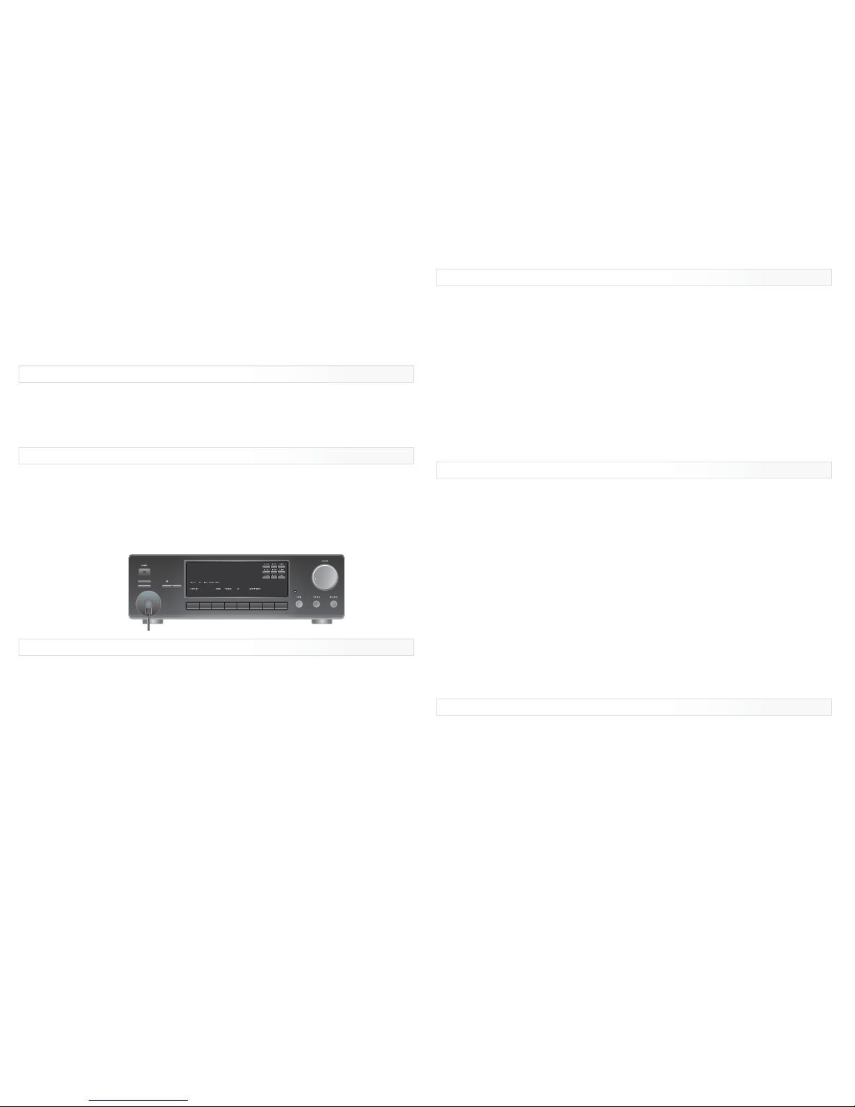
A component’s IR Receiver is normally located behind a tinted window on the front of
the unit you wish to control. The correct position might not be easy to locate. If this is
the case make a small hole (about 5mm (1/8in Diameter) in an opaque or white piece
of paper and place it over the front of the component and while sending a command
from the unit’s remote control handset, move the paper round until it responds to the
command.
Additional Information
If the system does not relay commands please refer to your supplier or check the
following;
• Some remote controllable components have poor quality remote control operation,
and may not be compatible with infrared relay systems. If other components operate
on the system the problem is likely to be in the component not the relay system.
• It is unlikely that the relay system would be intermittent due to the lack of power,
however, it may suffer from too much power. Holding the emitter away from the
component may improve performance. If this is successful a filter should be placed
between the emitter and the source component. Exposed photographic film is
recommended.
• Most relay systems work on a frequency of 38kHz, however, some products eg, cable
boxes and satellite receivers, operate at 56kHz. Some relay systems are not
compatible with this frequency or may only offer a short operating range compared to
other components.
• If an infrared receiver is in direct sunlight the operating range of the whole system
maybe reduced or become un-operational.
Blank Out Cover (Optional)
The emitter head is designed to pass infrared commands so a local remote control
handset can also be used. An optional blanking cover is provided for situations where
local operation is not wanted and to prevent commands being emitted to adjacent
components of the same type.
Blank Out Cover is a black IR opaque cover with a diameter of 1.2” (30mm) that fits
over both the Emitter shell and the IR sensor window of a controlled component. As an
optional accessory a blank out cover is supplied with each emitter head to prevent
unwanted external IR signals from passing through it or leaking past into other
components IR receivers.
• It is especially useful for zone controlled applications where you want the equipment
controlled only by the Emitter fastened over the component IR Sensor.
This emitter is a component of an infrared relay system. Please read the instructions
carefully to ensure it is properly connected.
The infrared emitter is a Light Emitting Diode (LED) which emits control commands via
infrared to an infrared receiver in your source component.
Installation
1. Before applying the emitter ensure the area around the infrared receiver window is
clean, dry and has no greasy film that could prevent good contact for the adhesive
pad/s.
2. Before removing the adhesive covers from the emitter or blanking cover find the
correct location of the emitter (See Emitter Placement) and test the unit’s operation. If
the blanking cover is used fit together before testing.
3. When the correct position has accurately been determined, remove adhesive cover
from the emitter and stick onto the IR sensor window. Take care not to let your fingers
touch the adhesive.
4. Two extra adhesive pads are supplied, which may be used;
i. to secure the cable lead to the underside of the component to prevent accidental
removal of the emitter
ii. to keep for future use if the emitter needs to be reapplied.
Specifications
EM-1 (Single Head Infra Red Emitter)
Contains;
1 x 3m Single Head Emitter
1 x Blankout Cover
3 x Extra double sided tape pads for the
emitter
EM-2 (Dual Head Infra Red Emitter)
Contains;
2 x 3m Single Head Emitter
2 x Blank Out Cover
6 x Extra double sided tape pads for the
emitter
Operation Manual
EM-1 & EM-2
Infra Red Emitters
 Loading...