

Page 1
Page 2
2
NOTE
Before starting, read this operating manual carefully in order to avoid improper use or
situations that may be dangerous for people, animals or objects. The manufacturer shall bear
no responsibility and shall exclude the possibility to apply guarantee terms in the following
cases: any misuse or use in improper conditions, any damage resulting from normal wearout or aging, inappropriate application, neglect, improper operation or storage, exposure to
moisture, arbitrary modication or repair, improper installation, using wrong power supply
source, operator errors, failure to obey this operating manual, or any other events for which
the manufacturer cannot be blamed, including any loss or damage in transport.
Page 3

3
CONTENTS
Note ..............................................................................................................................................................................2
Contents .......................................................................................................................................................................3
Introduction.................................................................................................................................................................5
Technical specication and description of the machine ....................................................................................6
Description of the machine ...................................................................................................................................... 7
Safety requirements .................................................................................................................................................. 8
Unpacking .................................................................................................................................................................10
Before each start-up ...............................................................................................................................................11
How to install and use the machine for the rst time .....................................................................................12
Cleaning ....................................................................................................................................................................14
Washing .....................................................................................................................................................................16
Control panel functions .........................................................................................................................................18
Switch-o procedure ..............................................................................................................................................20
Maintenance plan ....................................................................................................................................................22
FAQ .............................................................................................................................................................................23
Lamborghini burner error codes and ways they are indicated ......................................................................32
Diagnosis of burner equipment elements, errors and reasons for its operation blockage ....................33
List of spare parts, and the machine’s exploded view drawings ...................................................................34
CE Attestation of conformity ...............................................................................................................................41
Transport ...................................................................................................................................................................42
Final remarks ............................................................................................................................................................43
Page 4

Page 5

5
INTRODUCTION
Thank you for purchasing FORTADOR PRO+ industrial steam cleaner.
The FORTADOR brand is an eect of our long-standing experience and a response to our
Customers’ needs. The technology conned in the state-of-the-art housing provides for higher
power and performance as well as lower failure rate than ever before.
The solutions used, which only occur in FORTADOR steam cleaner, make it possible to make the
machine operation easier and faster. The possibility to feed two dierent detergents at the
same time is a solution that has never been used so far. The 7-inch touch display keeps the user
inform on the status of uids (water, fuel, detergents) inside the machine, and on the running
pressure of the boiler.
The heart of the machine is its boiler and burner assembly supplied by the world-renowned
manufacturer, Lamborghini Caloreclima. The highest quality of the combustion system and low
Diesel oil consumption provide for even faster return on investment. Additional 16.6 - 36.6
kW power regulation has made it possible for us to achieve working pressure in the range of
12 - 16 bar.
Manufacturer and Maintenance Service Provider
www.fortador.com
Page 6

6
TECHNICAL
SPECIFICATION
AND DESCRIPTION
OF THE MACHINE
Technical data
Power supply 230 V, 50 / 60 Hz or 110 V, 50 / 60 Hz
Power 650 W + 1150 W (vacuum cleaner)
Protection class IPX 4
Working pressure 12 - 16 bar
Maximum pressure 20 bar
Steam temperature
max. 140°C
Boiler temperature
max. 260°C
Fuel consumption 0,6 l / h
Boiler capacity 10,5 litres
Water tank capacity 25
Fuel tank capacity 15,5
Detergent 1 tank capacity 5
Detergent 2 tank capacity 5
Noise level 79 dB
Dimensions (W x L x H) (W x L x H) 77 x 140 x 100 cm
Weight
200 kg
(without uids and accessories)
Technical data are placed at the rating plate at the rear wall of the cover in the
area marked with the red frame. When contacting our Service Dept., please always
refer to your machine’s serial no. from the rating plate.
Page 7
7
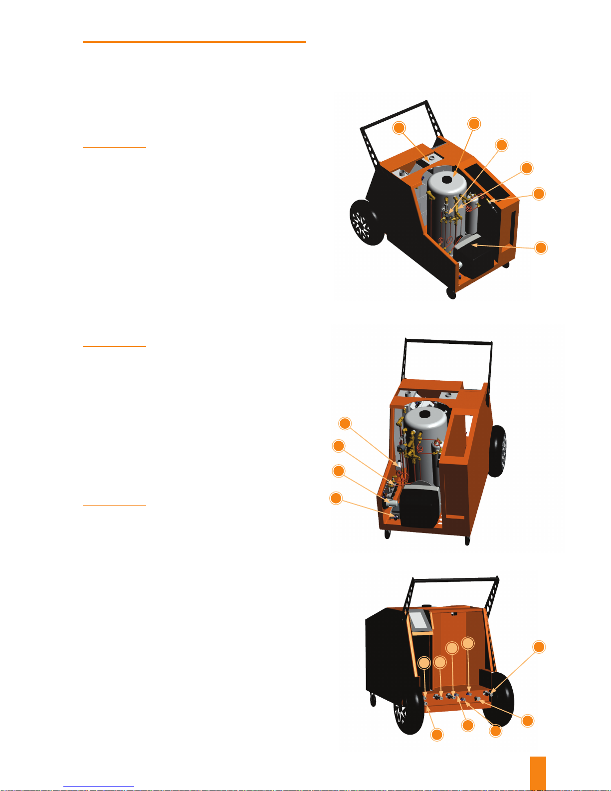
DESCRIPTION
OF THE MACHINE
1. Detergent, water, and fuel tanks
2. Boiler
3. Hydraulic line, washing – solenoid valve, valve
4. Hydraulic line, cleaning – wet steam sensor, skew lter
5. Pressure sensor (presostat)
6. Burner
1
2
6
7
8
9
10
5
3
4
13
14
17
19
12
15
16
18
11
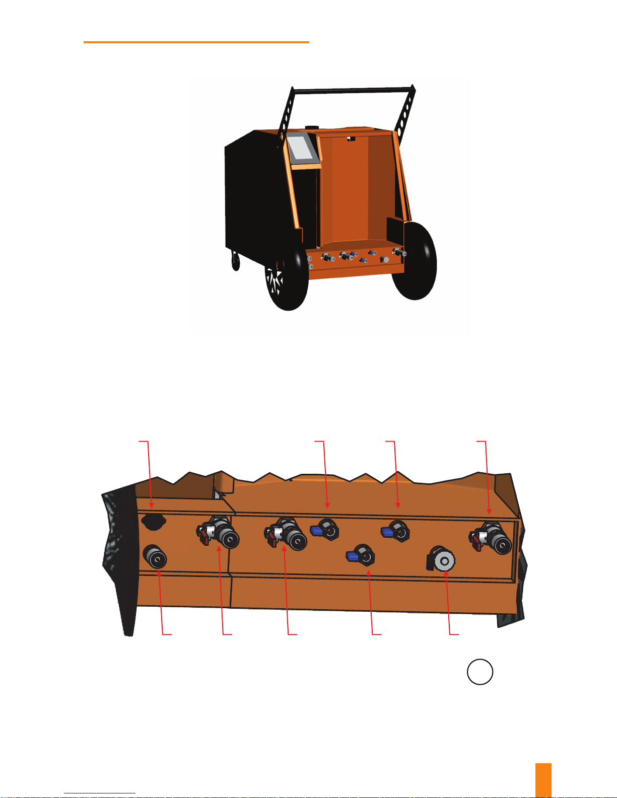
11. Washing hose power supply socket
12. Washing hose connection – quick connector
13. Cleaning hose connection – safety quick connector, valve
14. Cleaning hose connection – safety quick connector, valve
15. Water drain – valve
16. Detergent 1 drain – valve
17. Detergent 2 drain – valve
18. Permanent water connection – valve
19. Boiler steam drain – quick connector, valve
7. Fuel lter – fuel lter valve, tank fuel drain valve
8. Wet steam, detergent 1, detergent 2 pumps
9. Water lter
10. Water pump
Page 8

8
SAFETY
REQUIREMENTS
The FORTADOR steam cleaner is an industrial machine that must not be operated by persons who are not aware of hazards
associated therewith.
Guidelines and recommendations contained in this Manual must be properly understood and obeyed if the condition of the
machine proper and safe operation of is to be fullled.
Just as in case of most mechanical machines, all relative safety precautions must be observed while operating and servicing
the machine. Failure to observe this Operating Manual and recommendations contained in it may lead to injury or damage to
the machine or other objects situated nearby. At the same time, it must be borne in mind that it is not possible to present any
exhaustive guidelines or recommendations, which would make it possible to completely eliminate risks during its operation
or maintenance, and while handling or using chemical products that this machine has been designed to process. In case of
special applications and working conditions, some additional safety precautions can turn out to be necessary, which are not
discussed in this document. In such non-discussed cases, the user should obey generally adopted safety rules.
Before starting and operating the machine, please read this Operating Manual thoroughly.
This Operating Manual should be stored for later use or for the successive owner.
This machine heats up to high
temperatures! Protective gloves and
protective goggles must be worn
while operating the machine.
During operation, hearing protectors
must be worn!
Never use the machine without
wearing protective boots.
USE PROTECTIVE
GOGGLES
USE PROTECTIVE
BOOTS
USE PROTECTIVE
GLOVES
USE HEARING
PROTECTION
IMPORTANT:
Page 9
9
• Prior to each start-up, check residual-current circuitbreaker for proper operation in line with the procedure
as described in the “before each start-up” chapter. It is
forbidden to operate the machine with faulty residualcurrent circuit-breaker, as it may pose a threat of
electric shock!
• Do not submerge the machine or any of its components
in water or any other uids.
• It is strictly forbidden to use the machine in explosive
areas.
• Never use the machine close to toxic / hazardous
substances.
• Never install the machine on temperature-sensitive
foundations.
• Do not leave the machine in places exposed to the forces
of nature.
• Do not operate machine buttons / valves using excessive
force.
• The machine should be installed on stable level ground.
Make sure that its front wheels are secured during
operation.
• Never block the gun’s trigger.
• Never leave the machine working unattended.
• Do not direct steam jet towards electronic devices.
• While washing your car, make sure that the nozzle is
more than 10 cm away from the surface.
• When not in use, the machine should be switched o and
drained.
• Use only good quality fuel diesel. Use of any fuel
other than diesel, or any fuel that is contaminated or
diluted, may result in damage to the burner and loss of
guarantee.
• Remember that the hose bending radius can never be
lower than 10 cm. Bending the hose to a tighter radius
results in teon breaking, and, in consequence, in hose
damage.
• Operating pressure can be dangerous for people and
animals.
• Operators should be sober, adult, and trained in machine
operation and maintenance.
• Spare parts cannot be dierent than those
recommended and manufactured by the manufacturer.
• In case power supply cable is damaged, it must be
replaced by an authorised service-provider under pain of
loss of guarantee.
• Water tank must be lled with tap water only. Do not
add any detergents, chemicals, or descaling agents to the
water tank.
• Do not use distilled water!
• Before starting the machine, check if its operational
openings are free from dirt.
• It is only allowed to use original hoses and guns.
• Do not start the machine if its electrical cable or any
other part is damaged.
• Do not operate the machine in the rain or when it is wet.
• Never tilt or topple the machine when switched on.
• Always switch o the machine before cleaning.
• Children are absolutely not allowed to contact the
machine.
• Be careful while working near children or animals.
• Do not use the machine when damaged or when its
power supply cable shows any signs of damage. In case
the machine fails to work the way it should, if it fell or
got damaged or was left outdoors or ooded, contact
our service dept.: [email protected]
• Do not try to pull or lift the machine by its power supply
cable or hose.
• Watch for hoses, guns, lters, and seals. As consumables,
they are covered by limited guarantee only.
• Never direct steam towards people or animals.
• Keep the machine away from naked ame, radiators,
ovens or any other heat sources.
• Do not use the machine in any conned, insuciently
ventilated areas. Its fumes may pose a threat to your
health.
• Do not operate the machine in an environment with very
high humidity of the air and/ or highly dusted areas.
• When in operation, the machine should not be moved.
• The machine should be connected to electrical
installation that is provided with reliable earthing.
It is forbidden to operate the machine connected to
electrical installation no earthing, as it may pose a
threat of electric shock!
Page 10
10
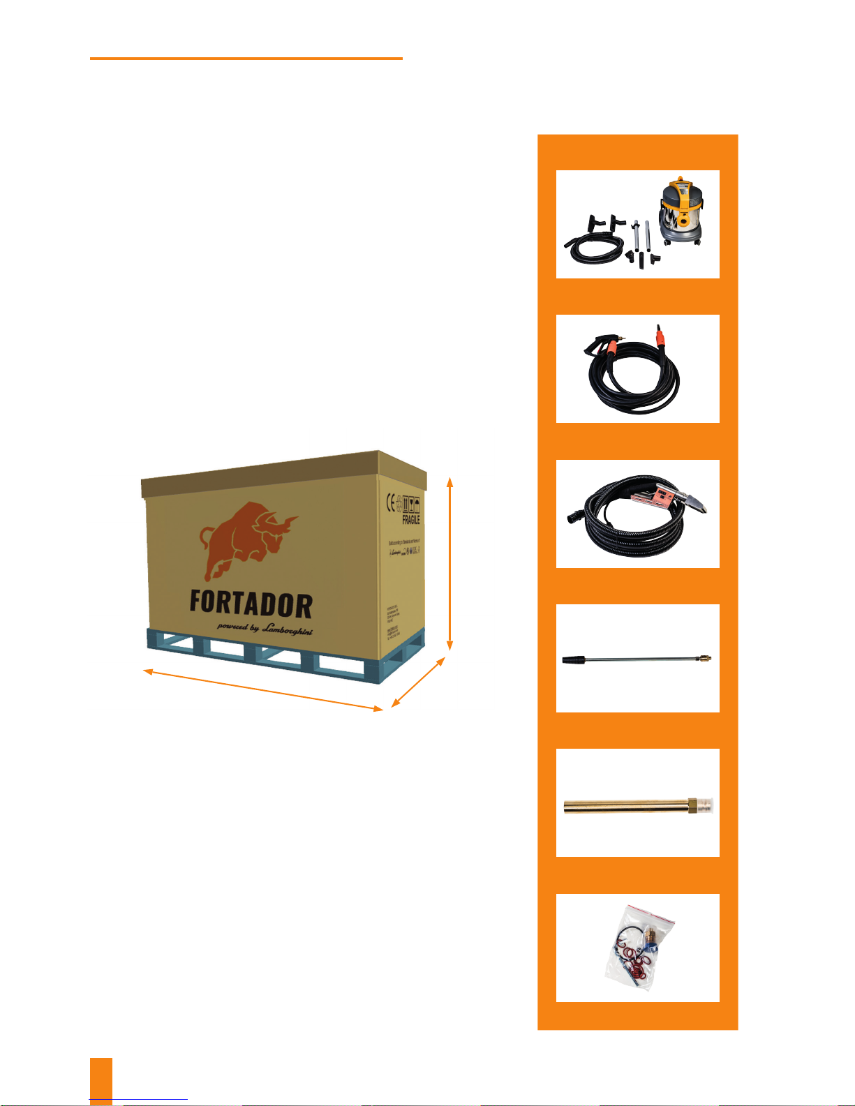
UNPACKING
1. Carefully remove the machine from its packaging.
2. Check if the machine has not been damaged while being
shipped.
3. Check if its standard equipment is complete. We
recommend to keep the packaging.
Vacuum cleaner
with accessories, 1 set
Short lance, 1 piece
Cleaning hose, 2 pieces
Boiler draining outlet
Dual washing hose, 1 piece
Repair kit
Packaging dimensions
STANDARD ACCESSORIES
153 cm
90 cm
116 cm
Page 11
11
In order to provide for the machine’s proper and safe
operation, this procedure should be conducted before it is
started.
1. Check if your hoses have been properly connected.
2. Make sure that your valves work properly.
3. Re-ll the water tank.
4. Make sure that your hoses and guns are not damaged.
5. Do not put any heavy objects on hoses, and do not drive
your car on them.
6. Make sure that your steam supply valves are closed if you
do not use your gun for a longer time (10 minutes).
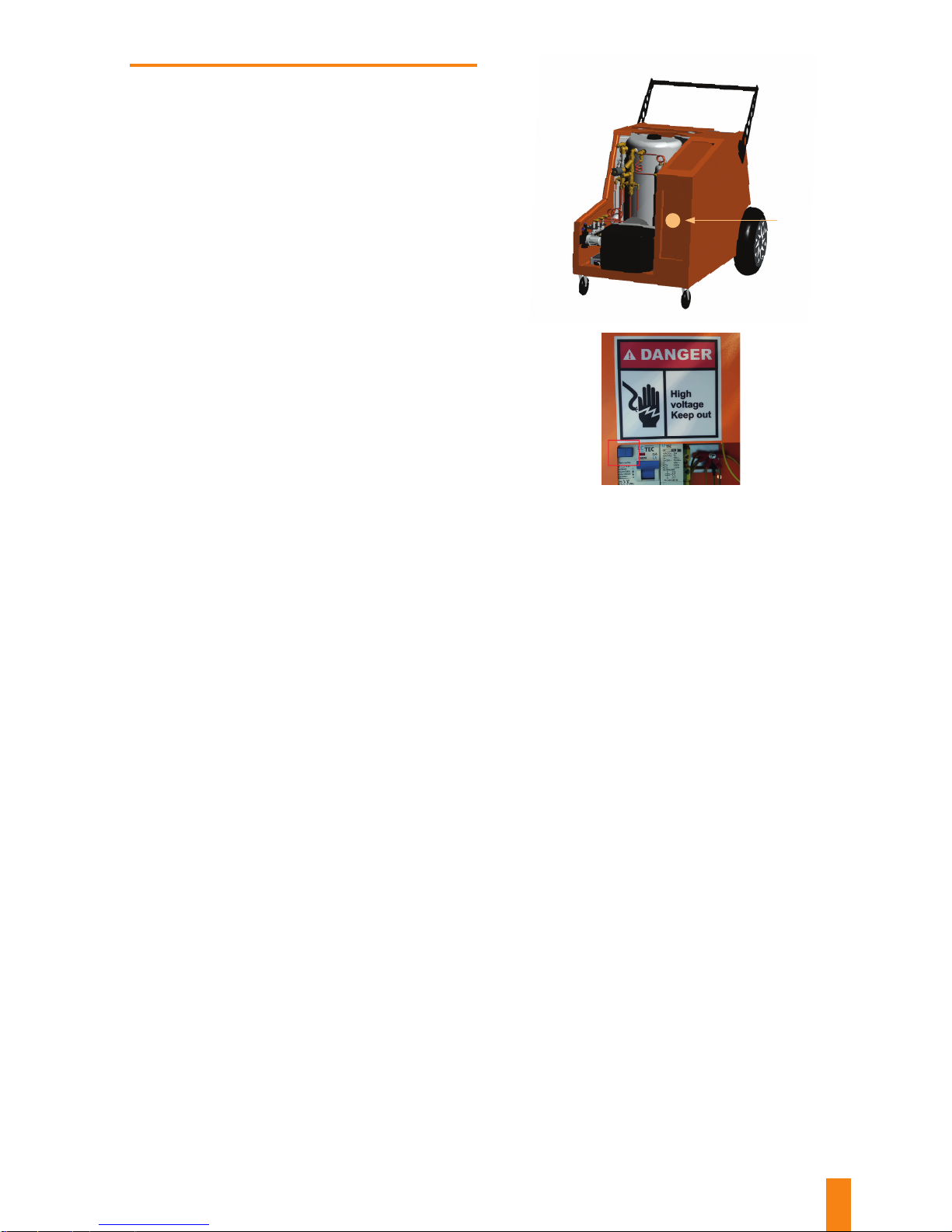
7. Check residual-current circuit-breaker operation by
pressing the Test button marked with a red square (the
machine should switch OFF). Operating the machine
with faulty residual-current circuit-breaker is strictly
prohibited.
8. Before starting the machine the operator should always
check cleanness and tight the cover of water and diesel
lter.
Residual
current circuit
breaker
Page 12
12
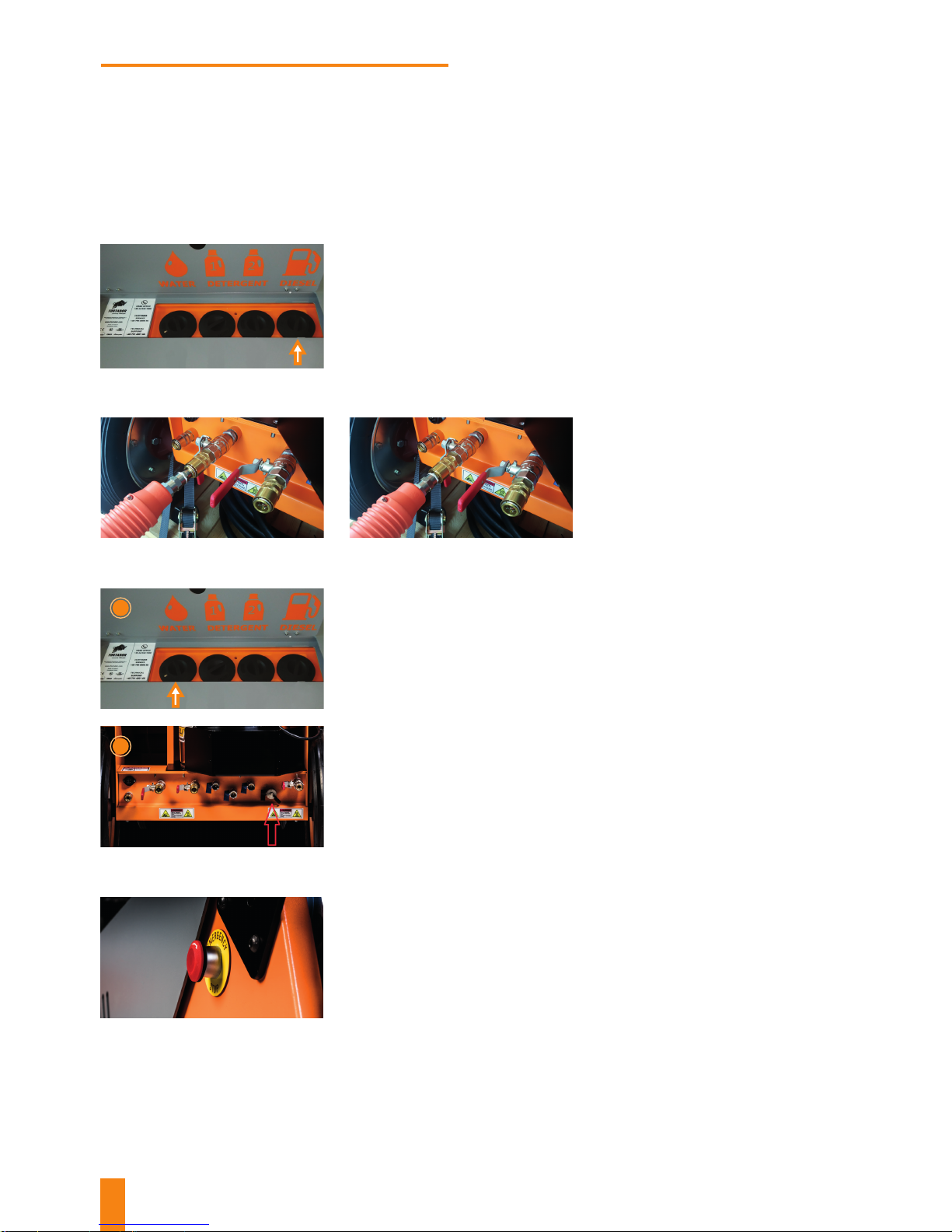
Wrong Right
HOW TO INSTALL AND USE
THE MACHINE FOR THE FIRST TIME
FORTADOR PRO+ machine starting procedure.
Re-ll the fuel tank with DIESEL as per the orange arrow
mark.
Re-ll the WATER tank (Photo no. 1) or connect the machine
to a permanent water connection (Photo no. 2). Use only
pure tap water (max. 25 l) or water with Lamborghini
softener (to extend the lifetime of your boiler and all
hydraulic assemblies).
Important:
Make sure not to start the machine before you pour the
water in.
Connect the hoses to quick connector.
Make sure that quick connector is
properly installed.
Connect the machine to a 230 V or 110 V socket (depending
on version of the machine), and turn the emergency stop
ring clockwise.
1
4
2
3
1
2
Page 13
13
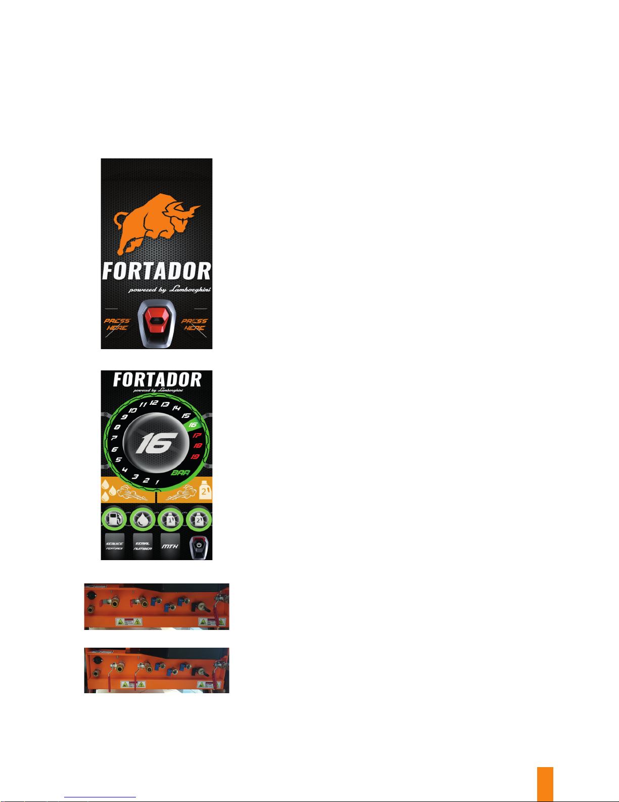
Make sure that hoses are connected correctly. Open steam
supply valves from the boiler to the hoses. Hold the gun
trigger pressed until steam starts to come out. Pressure will
drop for a moment. When the 16 bar pressure is reached,
the machine is ready to work.
Touch the button on the display to start the machine. The
machine will begin to automatically ll the boiler with water,
and the burner will be activated as soon as the minimum
water level is reached.
After 2-7 minutes, the pressure will reach 16 bar. Such
message will be displayed on the screen.
Valve open
Valve closed
5
6
7
Page 14
14
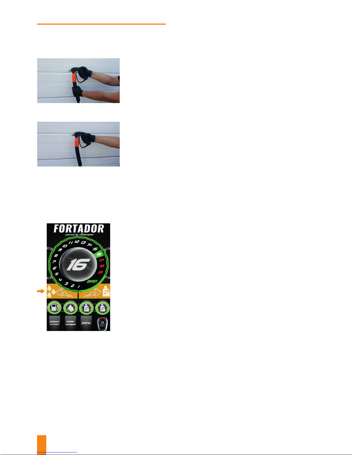
CLEANING
Holding the gun in both hands, press the trigger. Note: high
pressure results in gun recoil when its trigger is pressed. Be
careful! Work using both hands. Pull the hose, do not pull
the gun! Do not pull the gun by the hose!
While moving from one area to another, never pull the gun,
as this may lead to the connection of the hose with the gun
or the gun itself getting damaged.
Direct the steam jet towards the surface being cleaned,
making sure to keep a safe distance of 10 cm between the
gun nozzle and the surface being cleaned.
In case of heavy soiling, use the “wet steam” function
that is activated using the orange arrow marked button.
Steam being fed using the cleaning gun will additionally
contain water mist.
2
3
4
1
Page 15
15
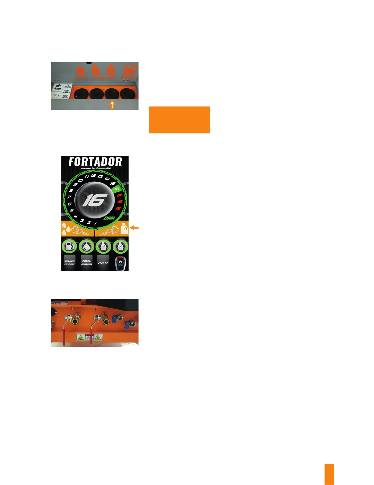
In order to remove heavy soiling, it may be required to use
some detergent together with steam jet. Before activating
this function, re-ll the DETERGENT 2 tank with detergent
diluted in water in proportions as described in the detergent
label. NOTE: Failure to obey this sequence may lead to
detergent pump getting damaged!
It is not recommended
to use high-foam and
acid pH reaction cleaning
detergents.
On the screen, activate Detergent 2 feeding, using the
button that is marked with the orange arrow.
Upon completion of work, close the steam supply valves to
the hoses, remove the steam that remains inside hoses by
pressing the gun’s trigger, and then disconnect the hoses
from the machine, and proceed in line with the “Switch-O
Procedure” Section.
5
6
7
Page 16
16
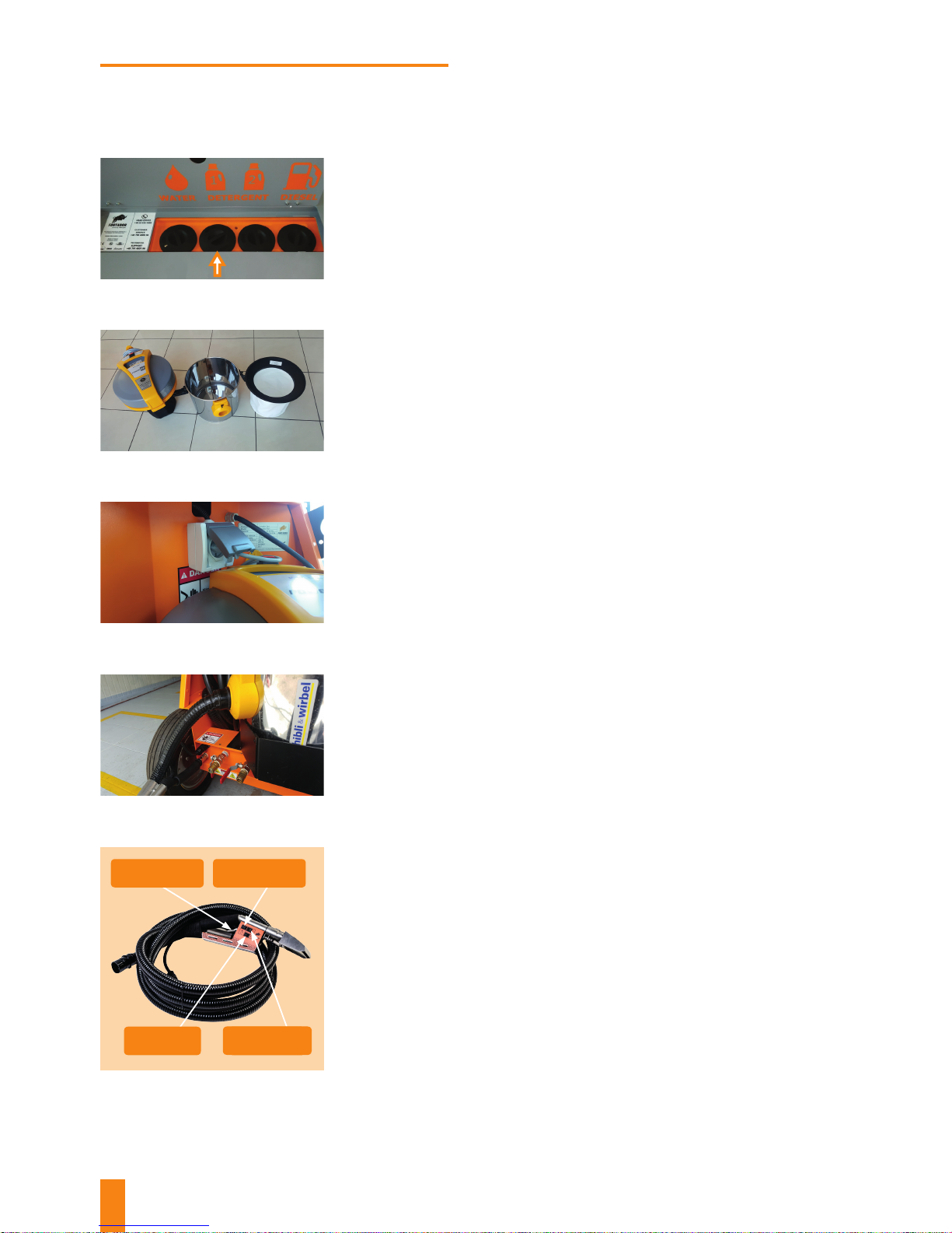
WASHING
Re-ll the DETERGENT 1 tank with the washing agent diluted
in water in proportions as described on the detergent label.
It is not recommended to use high-foam and acid pH
reaction cleaning detergents.
Remove the cloth lter from the vacuum cleaner.
Connect vacuum cleaner to the machine socket.
Connect 3 washing hose adapters:
Test your gun functions.
Gun button functions:
• suction pipe to vacuum cleaner;
• steam hose to quick connector no. 12;
• electric plug to socket no. 11.
• Trigger used to eject steam or steam with detergent
no. 1 (if the detergent-disposing button is pressed).
• Monostable button used to start detergent no. 1
feeding.
• Steam feeding ON/ OFF button.
• Vacuum cleaner ON/ OFF button.
1
2
3
4
5
Detergent 1
Feed
Vacuum
cleaner
Steam
Steam
feeding
Page 17
17
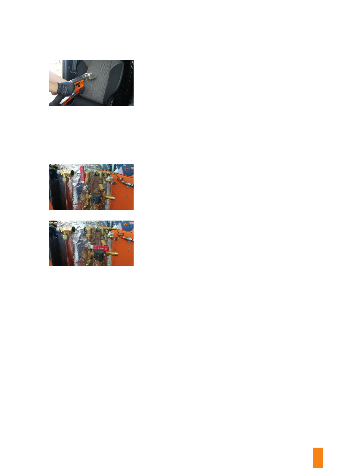
Start washing, making sure to move your washing gun only
from top to bottom (for a vertical surface) or towards you
(for a horizontal surface), dispensing the detergent all the
time to provide for best washing eects.
While washing, your vacuum cleaner should be kept switched
on all the time, so that it can draw in the condensed steam
from the surface being washed.
Upon completion of washing, empty your vacuum cleaner
container, disconnect the hose from the machine, and
proceed as in the “Switch-O Procedure” Section.
The volume of steam being dispensed using the washing gun
can be adjusted by means of the valve placed under the HOT
cover near the safety valve. In its vertical position, the valve
is completely open, and then the volume of steam being
dispensed is the highest. In its horizontal position, the valve
is completely closed, and then the steam is not dispensed
at all. Intermediary positions in between extreme positions
mean that the valve is partially open.
6
7
8
9
Valve open
Valve closed
Page 18
18
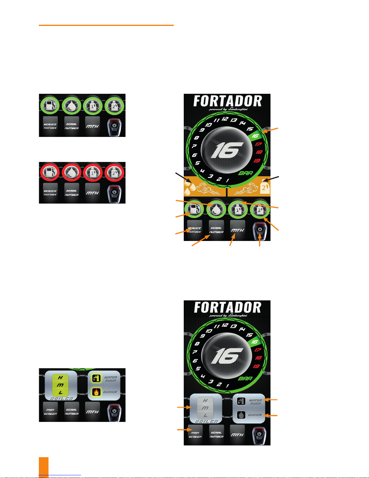
CONTROL PANEL
FUNCTIONS
Main screen
Current
boiler
pressure
indicator
Detergent 2 feed
starting button
(cleaning)
Service screen
Fuel level
indicator
Water level
indicator
Wet steam feed
starting button
Detergent 1
level indicator
(washing)
Detergent 2
level indicator
(cleaning)
Machine
STOP button
Work hour
count display
Machine serial
no. display
Green background of indicators
means that the uid level is sucient.
When indicators are shown with a red
background, it means that uids are
missing and that they should be re-
lled to continue operation.
Maintenance screen
Water pump ON
indicator
Boiler water
level indicator
Return to
Main Screen
Burner ON
indicator
Boiler water level indicator shows the
current water level (L – Low,
M – Medium, H – High) by backlighting
the relative indication in yellow.
When the water pump or burner is in
operation, its relative indicator will be
back-lit in yellow.
Page 19
19
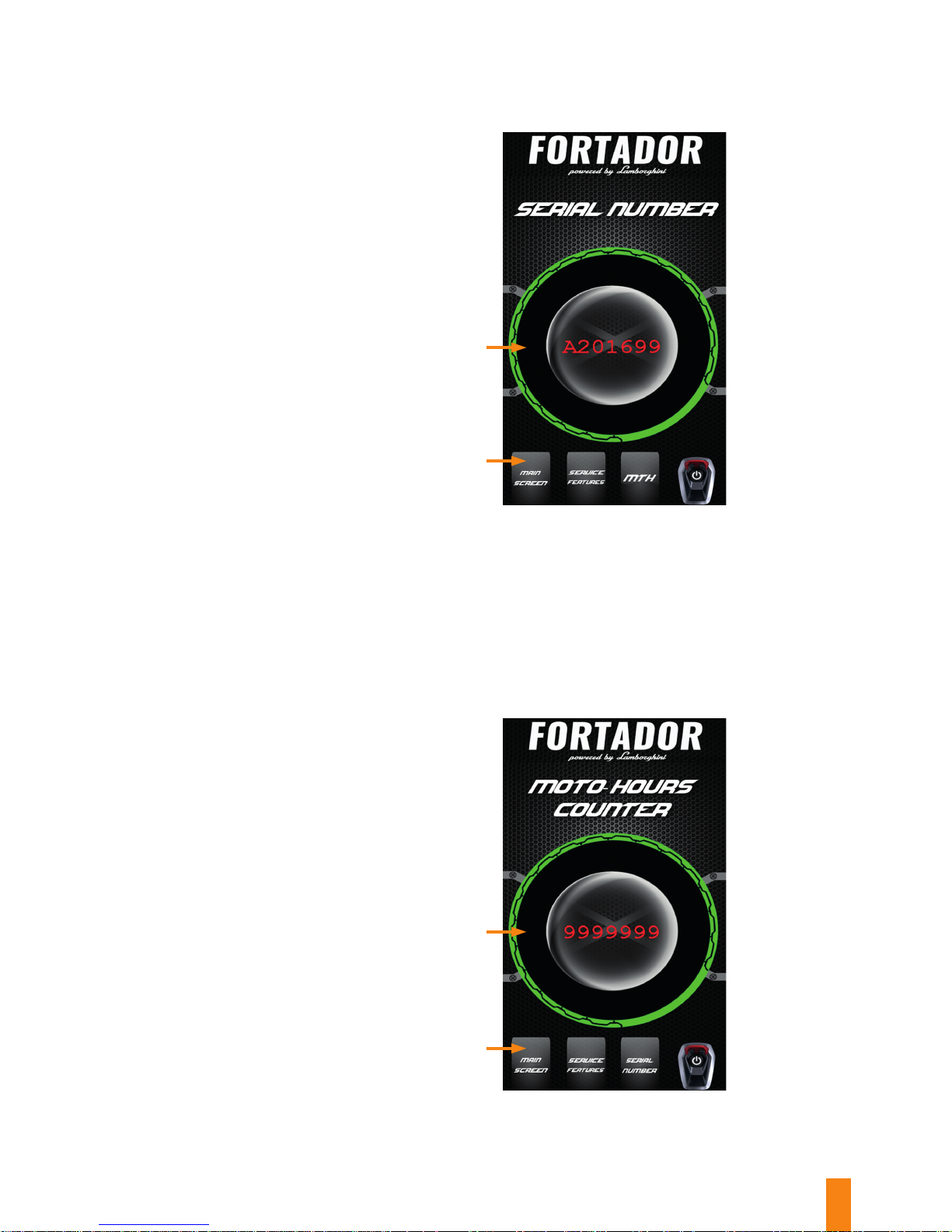
Serial no. display screen
Machine
serial no.
Return to
Main Screen
Return to
Main Screen
Worked hours count
display screen
Worked hours
count display
Page 20
20
13
14
17
19
12
15
16
18
11
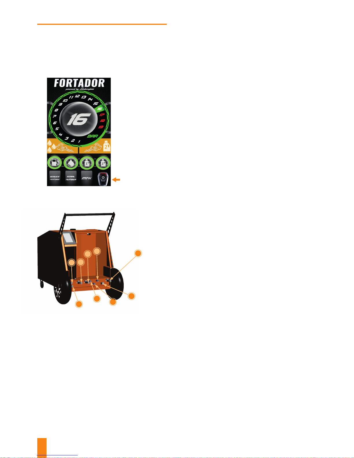
Switch o the machine using the button on the touch
screen, and then disconnect it from its power supply. NOTE:
Failure to observe this sequence may result in damage to
the machine’s controller.
Disconnect the hoses, clean them and roll them up,
being careful not to exceed the allowable bending radius
(min. 10 cm); NOTE: Bending the hose to any radius that is
tighter than allowed will result in its damage!
If the machine was connected to an external water supply
source, disconnect the supply hose from valve no. 18.
3
4
1
as presented herein.
Install the boiler draining outlet w quick connector no. 19.
5
2
Close the steam supply valves to the hoses (no. 13 and
14), press the gun’s trigger to release any steam that still
remains inside hoses.
Page 21
21
Clean the machine if dirty. By cleaning the machine each
time after you nish your work, you will keep it in very good
technical condition for a long time.
Place the machine so that the boiler draining outlet is
directed into the open space. Carefully open valve no. 19,
paying special attention to the steam that is coming from
the outlet. High-pressure steam jet may lead to serious
burns!
Leave the machine in dry, warm area that is free from dust.
Drain the boiler completely, leaving valve no. 19 in its open
position. This valve can only be closed just before you start
your work.
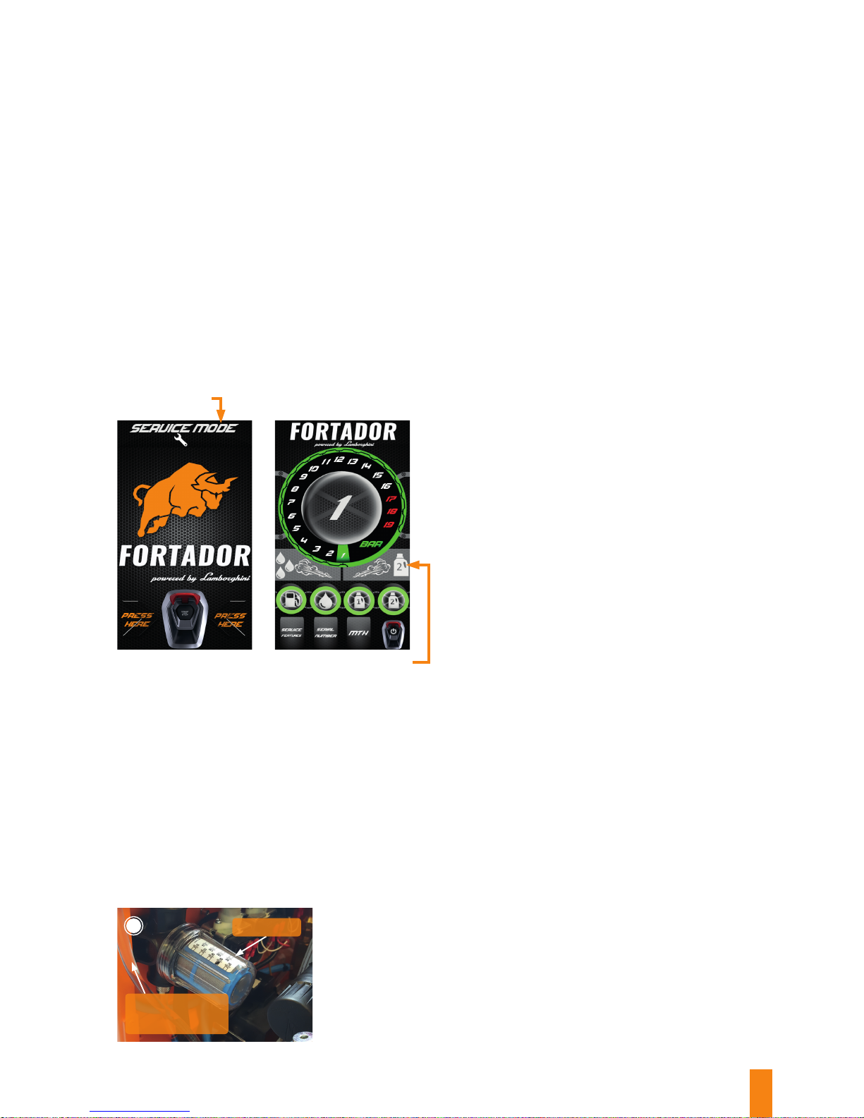
If the machine is to be stored in
temperatures below 0ºC (32 F), it
must be drained from all uids (water,
detergent, fuel) using valves no. 15,
16, and 17. Then, all the water must be
pumped out from the water system,
by entering the maintenance mode
by pressing the Maintenance mode
button that occurs for several seconds
in the upper part of the display when
the machine is started.
Afterwards, by pressing the DETERGENT 2 button, the water
pump will be run for 5 seconds pumping out any remaining
water from the water system into the boiler. Repeat this
procedure several times, watching if any water is still present
in the tube that supplies water into the water lter, and in
the lter itself. If you cannot see any water coming out, do
not start water pump any more to avoid dry running.
The last step is to remove the water from the water lter by
unscrewing its plastic dome and draining the rest of water.
When dry, re-install the dome on the water lter.
6
7
8
9
10
11
12
3
Maintenance mode
starting button
Button used to
start water pump in
maintenance mode
Water supply tube
from water pump
Page 22

22
MAINTENANCE PLAN
The FORTADOR steam cleaner is made of best materials. In order to keep it in
its perfect condition, it requires scheduled maintenance in line with the below
maintenance plan.
Within the guarantee period, scheduled maintenance must be performed by the
guarantee-issuing party or the authorised dealer. Failure to observe this condition
will result in loss of guarantee.
MAINTENANCE OPERATIONS
TIME INTERVAL
(WORK HOURS COUNT)
Clean the water lter and the fuel
lter
100
Check (water, detergent, fuel)
sensors
150
Check burner electrodes, and clean
the combustion chamber
200
Descaling
50 - 200 (depending on water
hardness)
Replace balls and springs in the
cleaning gun
200
Replace the vacuum cleaner motor 500 - 1000
Page 23
23
A
1 5 7 9
2 3 4 6 8
FAQ
Fig. 1
Fig. 2
Page 24
24
1
3
4
7
6
11
10
13
12
14
5
9
2
8
1
2
3
6
7
4
10
8
9
11
12
5
Fig. 3
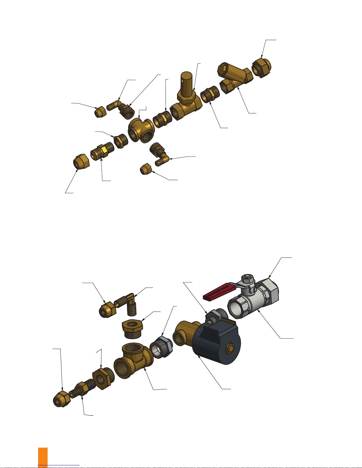
Steam line, cleaning
Fig. 4
Steam line, washing
Page 25
25
Freezing tubes in the boiler supply line in winter time,
bubbles in the water line tubes, broken water lter,
faulty water pump.
Damaged detergent tanks, damaged water tank.
No pressure in the boiler, or to the contrary: the display
shows pressure, while there is little steam at hose
outlets; boiler heats up insuciently and too long.
Stop the machine using the red button. Empty the boiler by opening the water drain valve and draining the steam
and rest of water. Open the water tank’s water drain valve in order to empty the water tank according to procedure
described in section “Switch-o procedure” points 10-12.
Open the water drain valves and detergent tanks Fig. 2 element 5 / 6 / 7. Empty the tanks from water and detergent
at temperatures below 0°C.
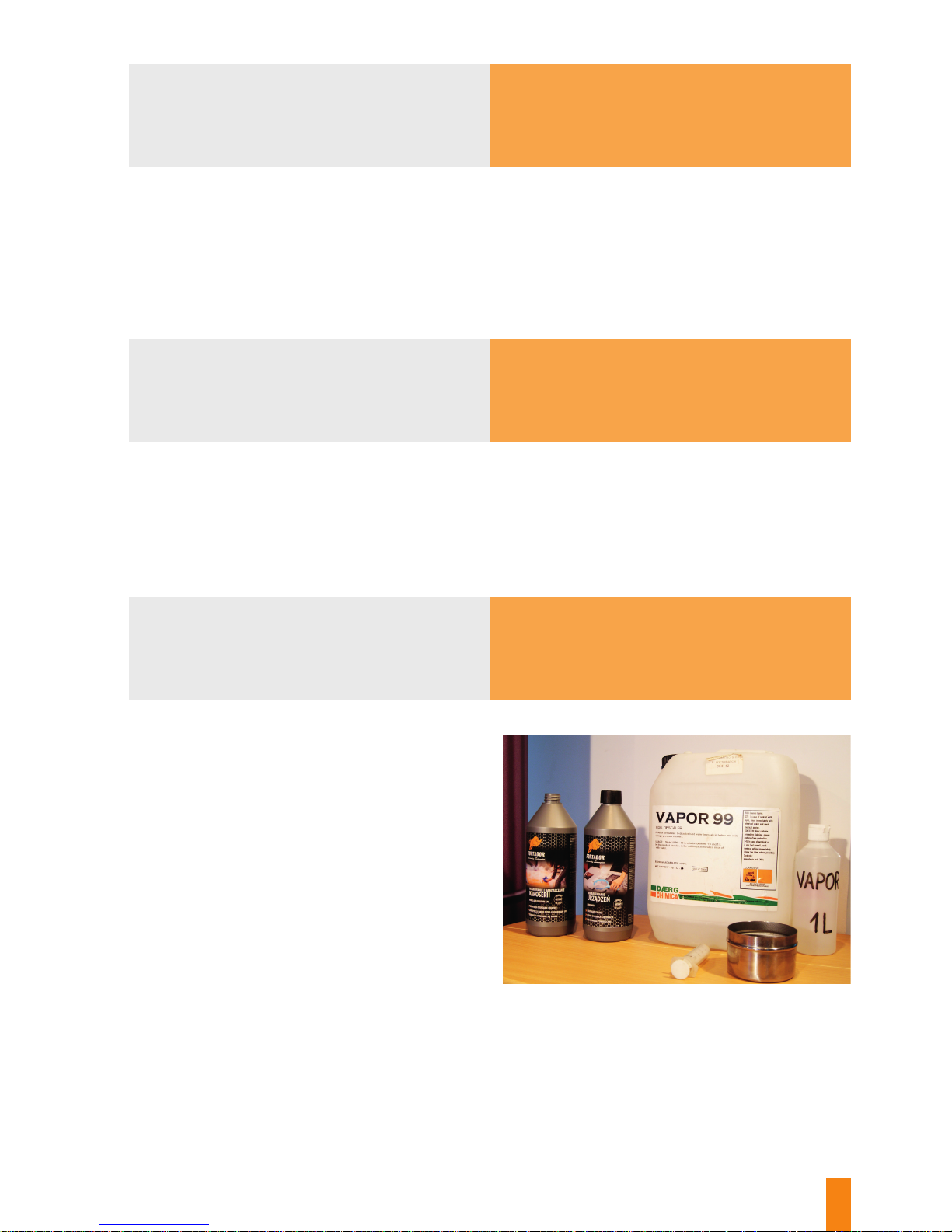
Perform the boiler descaling procedure using the
VAPOR preparation. Switch o the machine, connect
all cleaning and washing hoses to quick connector
properly. Washing hose as in Fig. 2 element 2, Cleaning
hoses as in Fig. 2 elements 3 and 4. Empty the boiler
and the water tank by opening drain valves (Fig. 2,
element 9). When the machine is stopped and emptied,
unscrew the coupling that connects the four-terminal
network with the copper tube (Fig. 3, element 1, and Fig. 4
element 1). Using a syringe, inject some VAPOR into
the copper tube. Wait till it starts to boil, and slowly
add small portions in order to thoroughly dissolve
the mineral deposit inside the tube. After approx.
20 minutes, re-connect the coupling to the four-terminal
network. Close the boiler drain valve and the water tank
drain valve. Pour approx. 1-2 litres of VAPOR into the
water tank. Start the machine, wait till the water pump
sucks the entire VAPOR in from the water tank.
As soon as the machine stops and begins to squeal, add
water into the tank. Pour the water in until the machine
starts both the burner and the boiler.
Replace water lter, replace water pump.
Replace tanks and level probes in uid tanks.
This indicates that the machine has been left in freezing
conditions at temperature below 0°C without having
emptied the boiler and the water ow line.
This indicates that the machine has been left in freezing
conditions at temperature below 0°C without having
emptied water and detergent tanks.
Scaled boiler, scaled steam outlet system and / or
cleaning / washing hoses.
1 problem
2 problem
3 problem
Diagnosis
Diagnosis
Diagnosis
Prevention
Prevention
Solution
Solution
Solution and prevention
Page 26
26
Steam rising from the quick connector area.
From time to time, you can hear a humming noise
coming from the machine, the vacuum cleaner refuses
to work or switches on all by itself every now and then,
or there is a problem with wet steam or detergent
presence.
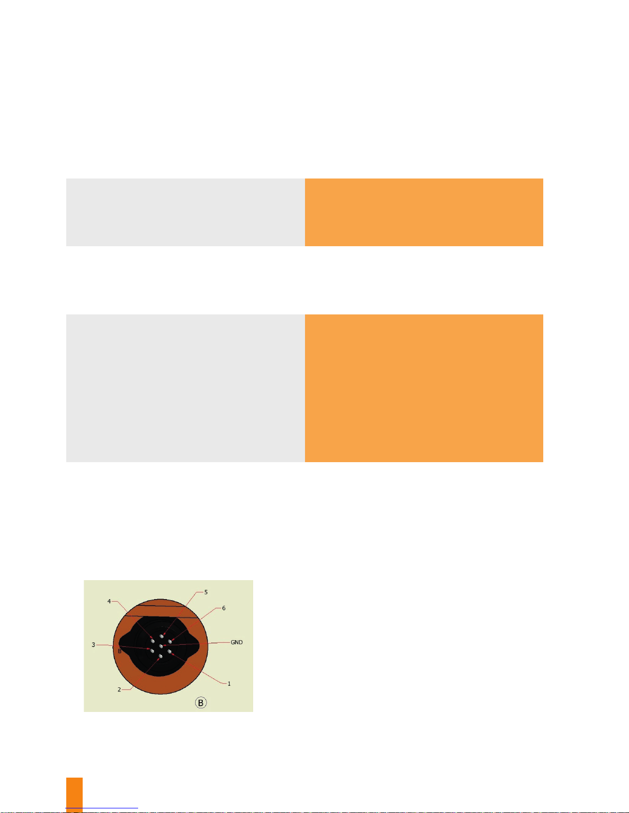
Pin 1 = free
Pin 2 = free
Pin 3 = free
Pin 4 + GND = vacuum cleaner ON
Pin 5 + GND = steam ON
Pin 6 + GND = detergent ON
Do not extend the washing hose, and do not pull the machine by the hose, as this may damage the control connector
/ plug or control cables inside the washing hose.
Replace control switches or cables inside the washing hose pipe. If the washing hose is old / worn out, replace it.
If any part of the vacuum cleaner hose is perforated, the hose cannot be used anymore: it must be replaced with
a new one.
Replace silicon O-rings in quick connector. When replaced, slightly moisten O-ring and quick coupling areas with
silicon spray grease.
Cleaning hose connector improperly installed in safety
quick connector.
One or several washing gun switches are damaged,
or silicon electrical cables in the washing hose are
damaged (broken, short-circuited, etc.). In the expected
steam / detergent / vacuum cleaner presence mode,
disconnect the washing hose control cable from Fig. 2
element 1, and perform a test at the control socket at
the rear panel of the machine by connecting pins as per
the diagram in Fig. 5 below. If the pin connecting test
is successful, it means that damage has occurred inside
the washing hose.
Fig. 5
View of the electrical connection socket for the washing hose
4 problem
5 problem
Diagnosis
Diagnosis
Prevention
Solution
Solution
When the boiler is heated up (16 bar), leave the
machine for approx. 5 - 30 minutes, depending on
the system’s scaling degree, in order to completely
dissolve the scale. When the scale dissolving process
is completed, ow the steam several times by
pressing the trigger at the successive hoses in order
to ush the silicon / Teon steam line and couplings
from any remaining scale. Completely empty the
boiler using the drain valve. Start the machine
2-3 times by lling the boiler, and heating and draining
it through the individual cleaning and washing hoses.
The machine is descaled now.
Obviously, depending on the hydraulic system’s ow
capacity (or scaling), scale can also occur in elements
Fig. 3 elements 1-13 and Fig. 4 elements 1-9, which
should also be cleaned within the descaling process,
depending on situation. Pay special attention to the
steam presence sensor (Fig. 3, element 11) which should
be installed / dismantled with special care and caution.
Page 27
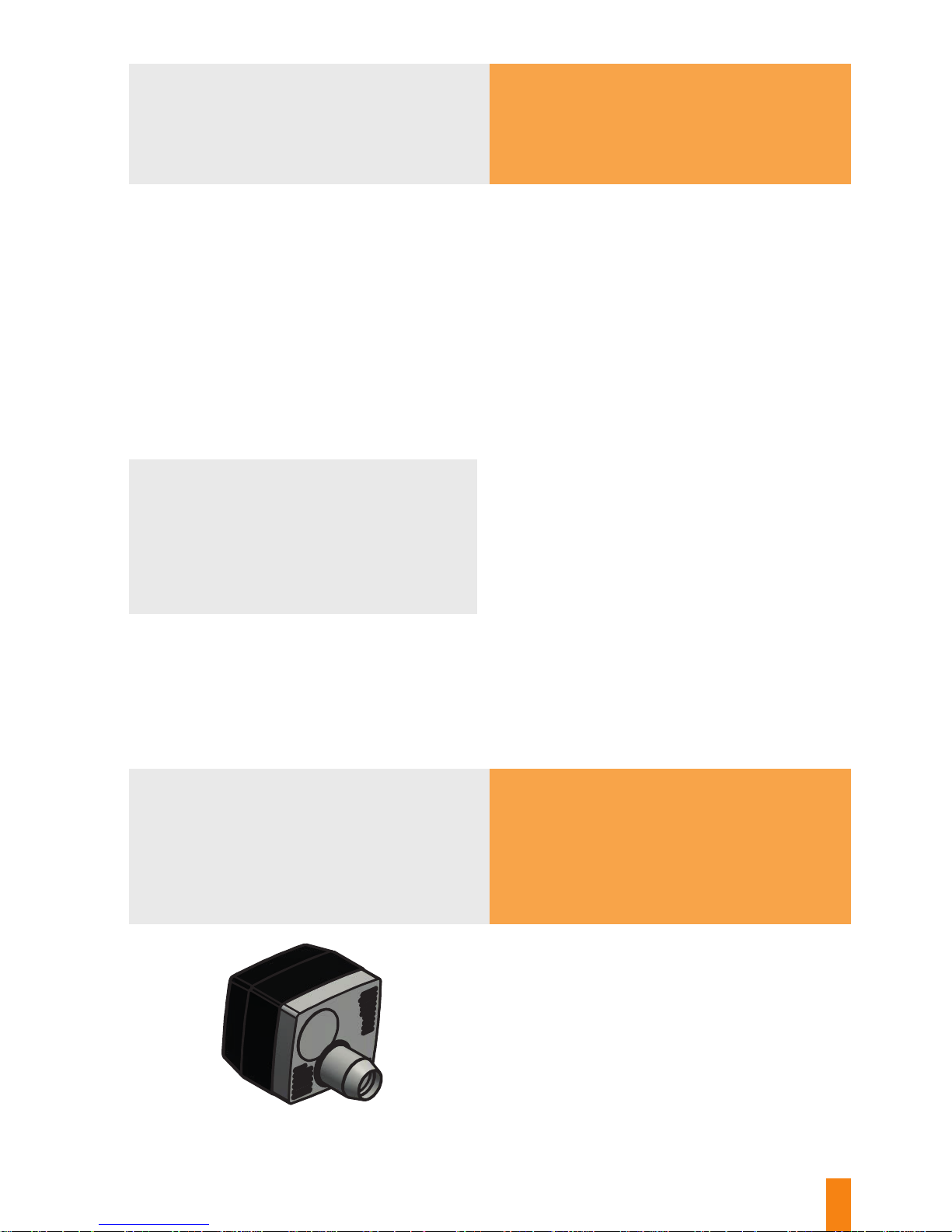
27
Regularly descale and protect the FORTADOR washer water line against freezing. Do not allow the water pump to
be run dry.
Fill them water tank to the full, so that the water level in the tank is above the water lter height. Loosen the water
lter cup, so that the lter can be freely lled with water, remove the transparent tube from water pump inlet and
let this tube ll up too, and then slide it fast back to its original location. Now the water pump should easily suck the
water in. While starting the machine, open the valve (Fig. 2 element 9) for a while, till such time as the water pump
overcomes boiler pressure and the water pump non-return valve opens (change in the water pump’s operating noise
from clattering to regular, mued noise).
NOTE: Long-term “dry” operation of the water pump results in permanent damage to the pump unit!!!
AD a) – replace the gun (or try to repair it by replacing gun valve ball and spring or by descaling gun valve with
a 50% chance of success in case of the cleaning hose, or replace the solenoid valve in case of the washing hose).
AD b) – replace in quick connector O-rings, and use silicon grease to provide for necessary slippage of the connector’s
friction elements. AD c) – replace the safety valve (it is worn out, and fails to fully close). AD d) – replace swivel joints
that connect the gun with the cleaning hose (worn out pipe silicon / Teon sealant).
Fig. 6
View of the Lamborghini burner
Always use proper and good quality fuel (heating oil
or winter fuel is not a good choice). The use of a high
quality fuel is a guarantee of repeatability of the
burner’s operating performance (no need to periodically
adjust composition of the fuel / air mixture, and the fuel
nozzle does not tend to wear out so fast).
7 problem
6 problem
8 problem
Diagnosis
Diagnosis
The machine refuses to start after the Start command,
does not ll with water up to the boiler L level that is
necessary to start the Lamborghini burner.
Worn out ET3000 water pump (or non-return valve that
is part of the pump, or pipe sealants inside the pump),
or air bubbles in the water line from the water tank to
the boiler.
Prevention
Prevention
Solution
Diagnosis and solutions
Steam coming from:
a) cleaning guns
b) cleaning hose quick-release connector
c) under the machine
d) cleaning gun handle area
Buzzing burner – characteristic vibrating noise, burner
assembly and boiler assembly are shaking in the
resonance (exhaust stream and jet pump inside the
boiler).
Change burner / boiler working conditions:
• Change the fuel (density, caloric value).
• Dierent atmospheric pressure than in the original
adjustment location.
• Dierent humidity of the air in the machine’s place
of operation.
Page 28
28
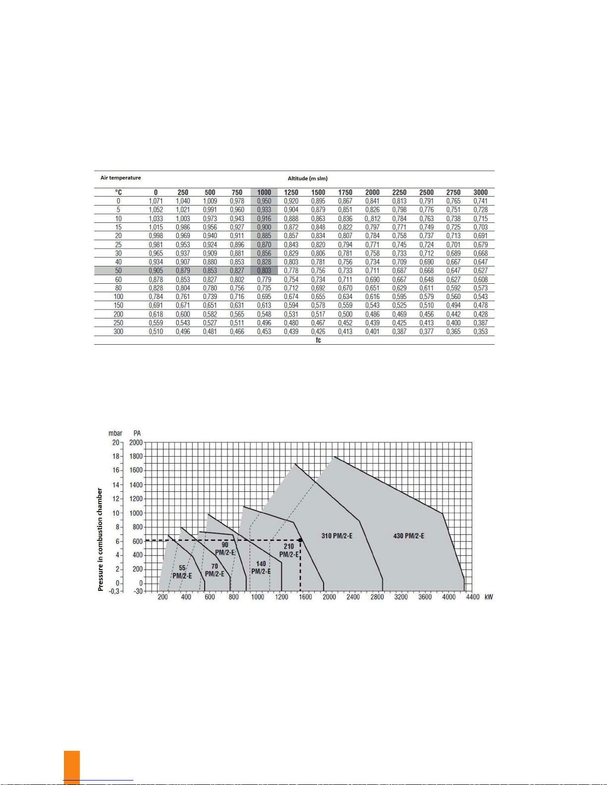
When we have a reduction of density of the air, there is, at equal volume, a lower amount of oxygen, so to burn the same
amount of fuel, it is necessary a bigger air volume. Since there is no possibility of increasing the air ow through the burner
ventilation, it is necessary to reduce the amount of fuel to be burned down. Of course with this setting there is a reduction in
the actual thermal power of the burner.
0 m above sea level (slm).
To quantify this reduction refer to the table below where the correction factor fc is returned to the dierent operating
conditions:
• -hearth input Qf = 1,259 kW
• -pressure in combustion chamber Pcc = 6.2 mbar
• -altitude installation: 1000 m slm
• -Inlet air temperature: 50 °C
Page 29
29
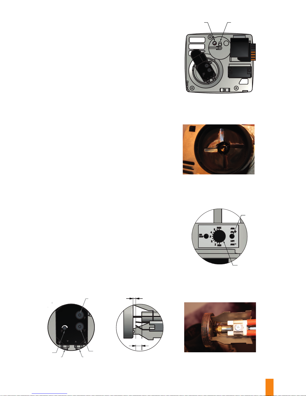
Fig. 7
View of the burner from the rear
Fig. 8
View of the damaged fuel head
in the burner
D
12
Properly adjust the composition of the fuel / air mixture.
Remove the burner’s black cover.
a) Make sure that the burner’s heating power setting
corresponds to boiler size. This adjustment is made using
Fig.7 element 1 by turning a screwdriver to the left or right.
b) Initial setting of the air damper is made by turning the
adjustment screw Fig. 9, element 1, for approx. 1 level in line
with Fig. 8, element 2.
c) Using a hexagonal Allen wrench no. 4, turn the knob to
the left to the end as in Fig. 10, element 1, and then turn the
wrench clockwise 1 – 1.5 turn to the right.
Carefully watching the boiler’s chimney outlet (there
should be no black or white smoke), adjust fuel amount to
a satisfying dose (typical setting in the range from extreme
left position + 1 turn to the right to 2.5 turns to the right).
Make sure that the burner-boiler assembly does not shake in
the resonance (characteristic loud rumbling noise). In case
fuel pump adjustment range is insucient, adjust the air
damper Fig. 9, element 1 (typical setting range: 0.5 - 2.0).
This setting and precision adjustment should be conducted
several times until a light ame is achieved in the direct view
window as in Fig. 7, element 2. The target adjustment should
be performed on a heated machine during a third or fourth
boiler heating (normal operation mode), whereas precision
adjustment refers to the machine’s cold start procedure.
NOTE: Since it is not possible to adjust the burner by
performing steps as above, the fuel nozzle must be worn
out. Dismantle the burner and replace the nozzle.
NOTE: Watch for proper installation of fuel supply line
(Fig. 10 element 5) and fuel return line (Fig. 10 element 4)
as per Fig. 10.
Fuel nozzle replacement should be accompanied by proper
setting of ignition electrodes. Distance from nozzle head to
ignition electrodes, and from ignition electrodes to the swirl
vane: as in Figures 11 and 12.
Solution
Fig. 9
View of the air damper
regulator
Fig. 10
View of the fuel pump
A
1
2
A
2
5
3
1
4
D
P
P
V
D
Fig. 11 Fig. 12
2,50~
2,50~
C
C
Page 30
30
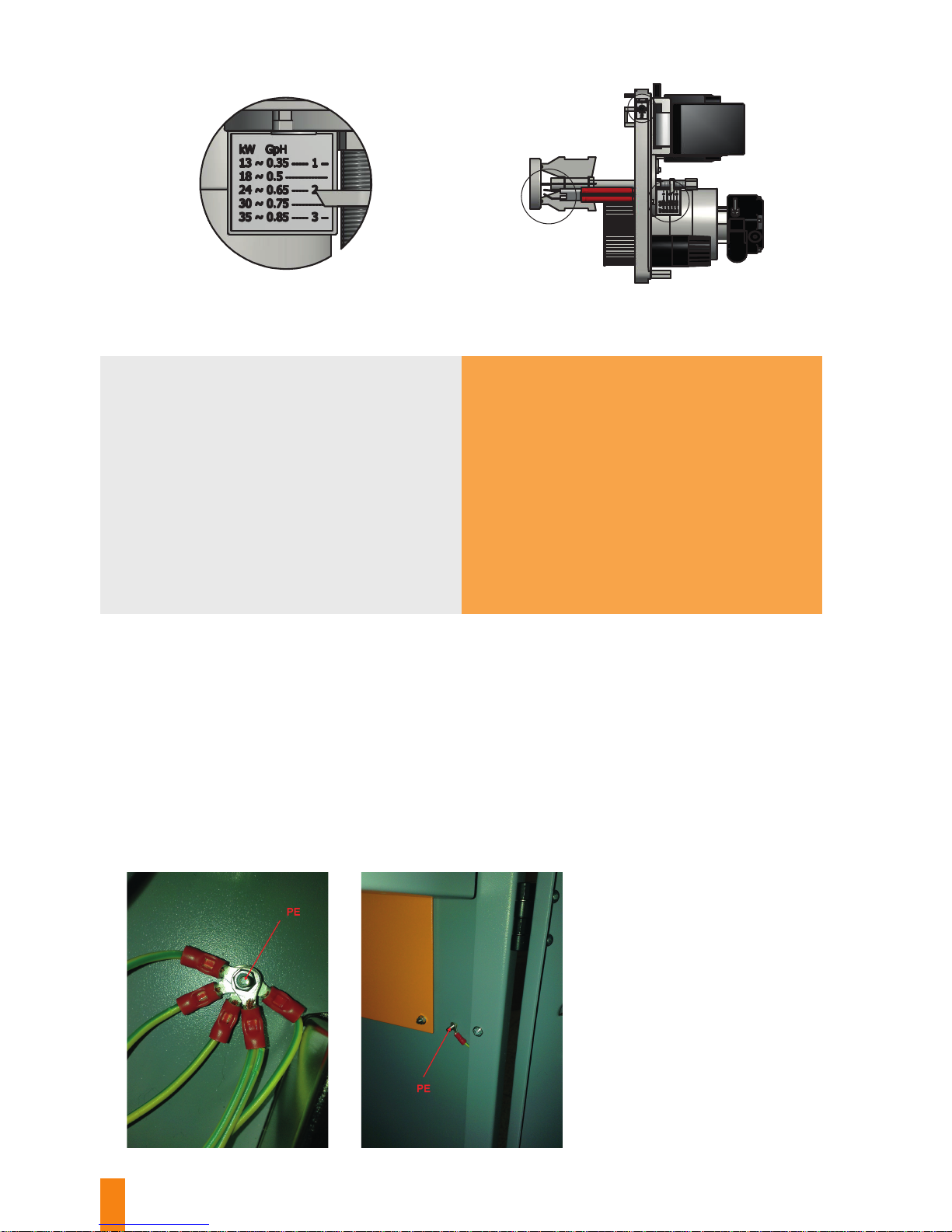
View of the burner having been removed from the machine
View from the top, with its protective cover removed
Setting the burner’s heating power in line
with the plate placed as in Fig. above
A
B
C
B
B
9 problem Diagnosis
Prevention
Solution
Touching the machine or the hose results in a soft
tingling feeling.
• Electrostatic charge build-up on the surface of
the machine (gas or liquid ow in plastic or Teon
hoses).
• High humidity of the air in the machine operation
location, especially in Asian countries or weakly
ventilated rooms.
• Possible washing gun breakdown as a result of
excessive moisture in the installation / switches of
the washing gun.
• Possible breakdown as a result of damaged control
cables in the washing hose (silicon cable insulation
damaged).
Provide for good, sucient ventilation where the machine is operated. Do not pull the washing hose exerting
excessive force (as this may result in damage to the rope that limits washing hose length and in failure / rupture
of the control cable insulation in the washing hose). Regularly inspect electrical installation for the condition of
insulation and earthing (especially the earth wire). From time to time, check the temporary electrical installation, i.e.
all sorts of extension cords or adapters. It is not allowed to use any double-wire or garden extension cords. Use only
extension cords in double rubber insulation designed for outdoor use.
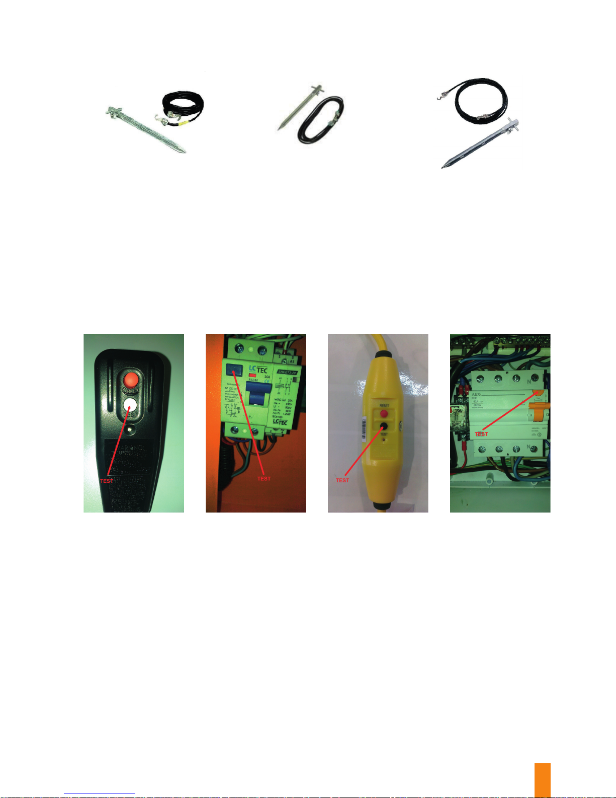
Use additional grounding for the machine in the form of low-resistance earthing rod driven into the earth and
connected to the body of the machine with a copper rope minimum 4mm2 in order to dissipate electrostatic charge
build-up. Earth wire connection locations in the machine: as in Figures below.
Page 31
31
One of conditions of proper protection against electric shock is that the machine’s electrical installations must be periodically
inspected by entities authorised thereto to. Pay special attention while you repair or adjust your machine, as most of its
elements are very hot, and you can get serious burns if you touch them directly. Since this is a pressure machine, be careful
when you operate or adjust it. In the event its pressure system is unsealed when in operation, you can undergo severe burns
from high-temperature steam. Persons who perform maintenance / adjustments at this machine should hold relative permits
and logbooks that allow them to carry out maintenance/ adjustments on thermal pressure equipment (Group G2 energy
licence) and electrical equipment (Group G1 energy licence).
Residual-current circuit-breaker with overcurrent protection protects the user against touch voltage and leakance. It is
absolutely necessary to test it as described in “Before each start-up” chapter by pressing the Test button in normal operation
mode. When the Test button is pressed, this safety device should be activated to disconnect power. In various machines’
residual-current circuit-breakers, the Test button is located as below.
Page 32

32
If the burner is in the blocked mode, it will be indicated by non-ashing red colour
of the LED at the back-lit button on top of the burner. By pressing transparent
button on top of the burner for a short time only, the entire burner start, operation
and self-diagnosis control process is skipped. By pressing this transparent button
and holding it depressed for at least 3 seconds, the burner start and diagnosis
control process is commenced (the red light will ash fast). The Table below
explains some possible burner blockage cases, depending on error occurrence in
the burner start and self-diagnostics procedure. This information is available by
counting the number of ashes of the red LED (always the red one). The diagnosis
function can be discontinued by pressing the button on burner enclosure and
holding it depressed for at least 3 seconds.
Lamborghini burner error codes
and ways they are indicated
MACHINE STATUS INDICATOR
Condition LED colour
Standby mode, other intermediary
modes
No light
Fuel heating in the burner starting
phase, waiting time max. 5 seconds
Yellow
Fuel / air mixture ignition stage Yellow, ashing
Proper operation Green
Improper operation, the infrared sen-
sor cannot see any ame
Green, ashing
Voltage drop Yellow / red, ashing alternately
Burner blocked Red
Error Red, ashing
Scattered light on the sensor prior to
mixture ignition
Green / red, ashing alternately
Self-diagnostics Red, quick ashing
Page 33

33
List of Anomalies
Visual information Possible reasons
2 ashes
No ame presence signal from the infrared burner sensor
• damaged fuel valve,
• damaged ame detector,
• improper burner fuel / air mixture composition setting,
or no fuel,
• no ignition.
3 ashes N/A
4 ashes
“Wrong” light during the mixture ignition procedure;
ame detector has sensed improper ignition or leakage
in the combustion chamber
5 ashes N/A
6 ashes N/A
7 ashes
No ame presence signal from the infrared burner sensor
during burner operation:
• damaged fuel valve,
• damaged ame detector,
• wrong burner fuel / air mixture composition setting,
or no fuel.
8 ashes Fuel pre-heating time disturbance
9 ashes N/A
10 ashes
Wrong electrical power supply or internal failure
of burner controller
Diagnosis of burner equipment
elements, errors and reasons
for its operation blockage
Page 34
34
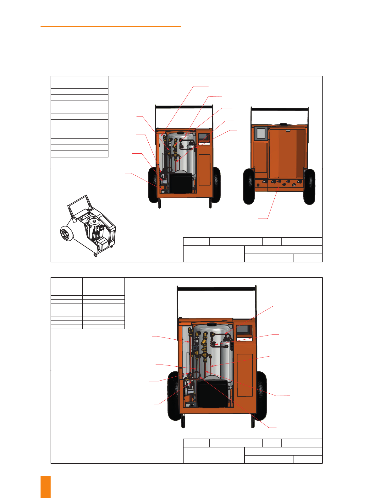
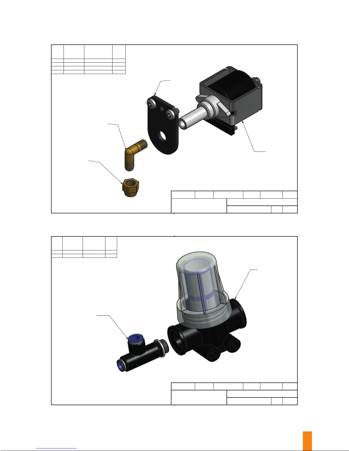
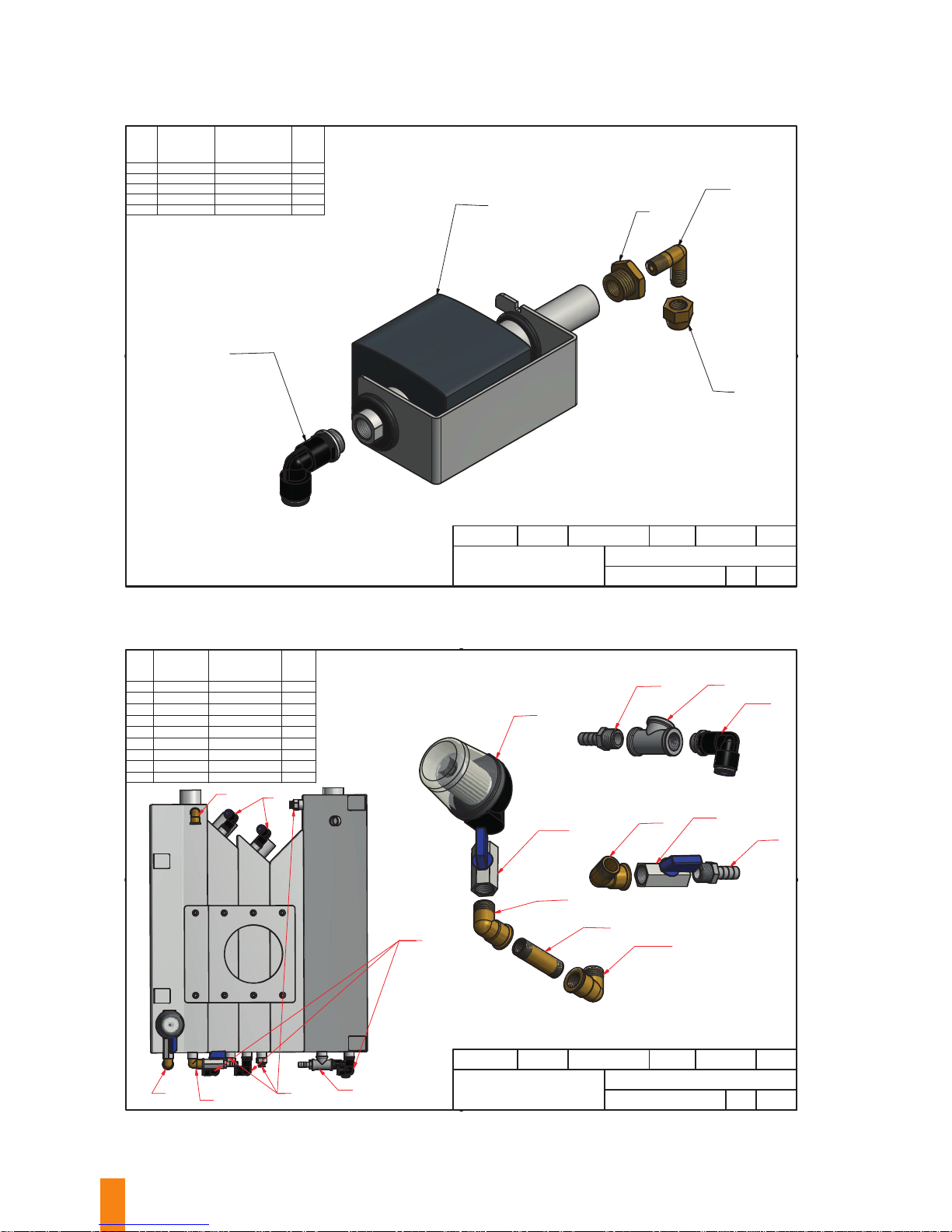
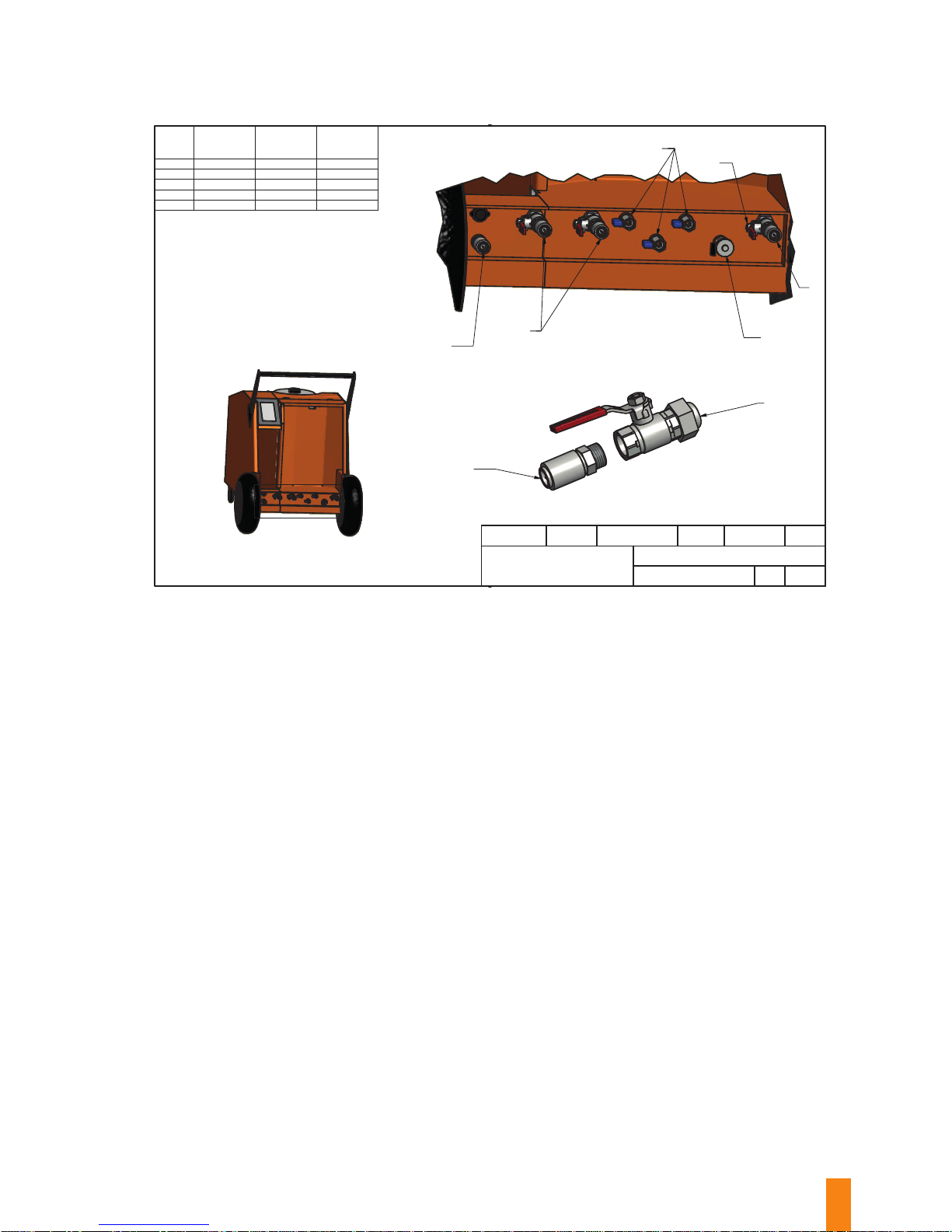
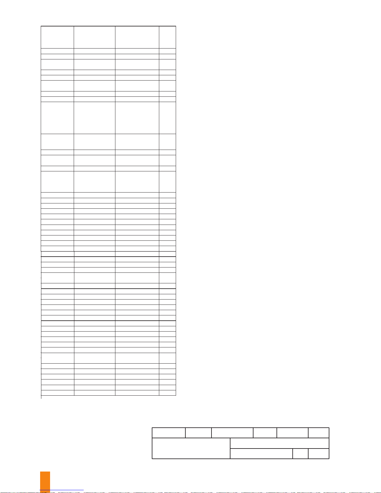
List of spare parts, and the machine’s
exploded view drawings
Fortador PRO+
PRO-000-000
FORTADOR
Drawing is owned by FORTADOR. Use and distribution
without the consent of the owner is prohibited.
Anna Wiraszka
Andrzej Nocuń
Janusz Mizerski 2016-12-05
1 : 11
Drawn by
Checked by Approved by
Date
1 / 1
Scale Sheet
2
3
4
5
6
7
9
No.
Draw No.
1. PRO-000-001
2.
PRO-000-002
3. PRO-000-003
4. PRO-000-004
5. PRO-000-005
6. PRO-000-006
7. PRO-000-007
8. PRO-000-008
9. PRO-000-009
10. PRO-000-010
11. PRO-001-000
10
1
8
Fortador PRO+
PRO-000-001
FORTADOR
Drawing is owned by FORTADOR. Use and distribution
without the consent of the owner is prohibited.
Anna Wiraszka
Andrzej Nocuń
Janusz Mizerski 2016-12-05
1 : 8
Drawn by
Cheked by Approved by
Date
1 / 1
Scale Sheet
No.
1.
001/1
SH00085
-
2.
001/2
SH00085
-
3.
001/3
SH00085
-
4.
001/4
SH00085
-
5.
001/5
SH00085
-
6.
001/6
SH00085
-
7.
001/7
SH00085
-
8.
002/1
SH00084
-
9.
002/2
SH00084
-
1
2
3
8
9
5
6
7
4
Part No. Catalog No.
Quantity
Page 35
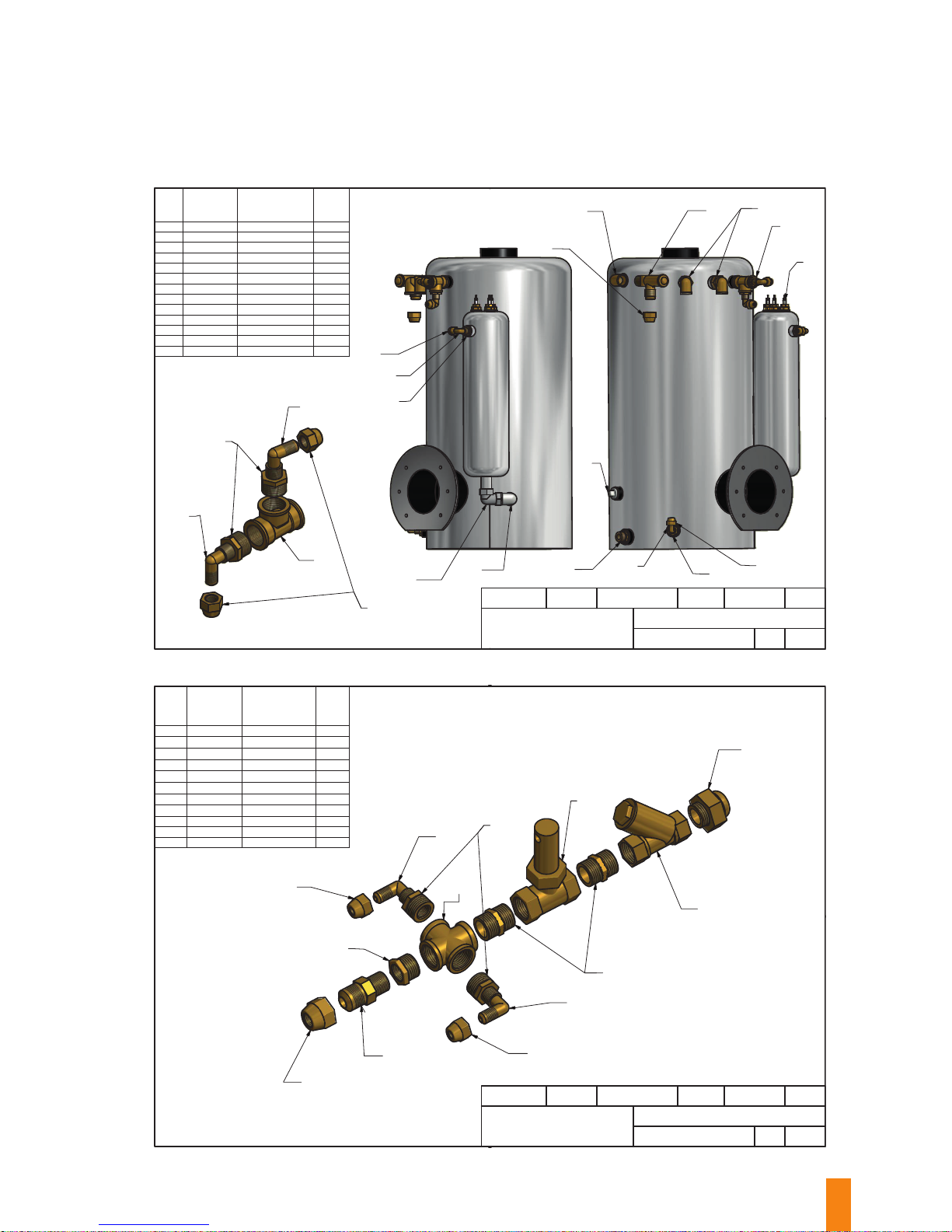
35
Fortador PRO+
PRO-000-002
FORTADOR
Drawing is owned by FORTADOR. Use and distribution
without the consent of the owner is prohibited.
Anna Wiraszka
Andrzej Nocuń
Janusz Mizerski 2016-12-08
1 : 5
Drawn by
Checked by Approved by
Date
1 / 1
Scale Sheet
No.
1. 003 SH00103 2
2.
004 SH00019 1
3. 005 SH00127 1
4. 006 SH00046 1
5. 007 SH00032
1
6. 008 SH00080 1
7. 009 SH00047 4
8. 010 SH00071 4
9. 011 SH00105 1
10. 012 SH00116 1
11. 013 SE00154 3
12. 014 SH00023 4
13. 015 SH00026
1
1
2
3
4
5
6
7
14
7
8
9
13
11
A
A
7
8
10
A ( 1 : 2 )
Part No. Catalog No. Quantity
14
14
12
8
Fortador PRO+
PRO-000-003
FORTADOR
Drawing is owned by FORTADOR. Use and distribution
without the consent of the owner is prohibited
Anna Wiraszka
Andrzej Nocuń
Janusz Mizerski 2016-12-05
1 : 2
Drawn by
Checked by Approved by
Date
1 / 1
Scale Sheet
2
3
4
5
6
9
8
10
11
No.
1. 009 SH00047 2
2. 006 SH00046 1
3. 016 SH00069 1
4. 017 SH00073 1
5. 010 SH00071 2
6. 018 SH00011 1
7. 014 SH00023 2
8. 019 SE00006 1
9. 020 SH00050 2
10. 021 SH000 17 1
11. 022 SH001 03 1
Part No.
Catalog No.
Quantity
7
7
1
1
Page 36
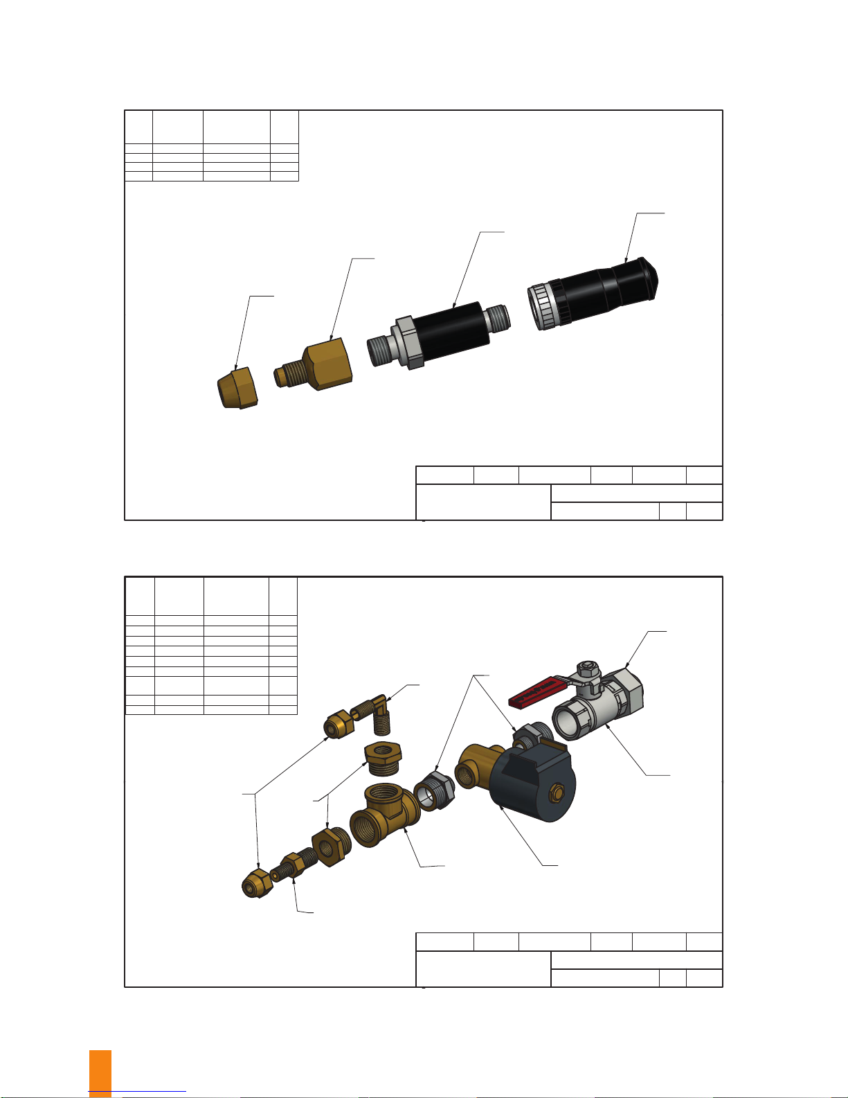
36
Fortador PRO+
PRO-000-004
FORTADOR
Drawing is owned by FORTADOR. Use and distribution
without the consent of the owner is prohibited.
Anna Wiraszka
Andrzej Nocuń
Janusz Mizerski 2016-12-08
1 : 1
Drawn by
Checked by Approved by
Date
1 / 1
Scale Sheet
No.
1. 009 SH00047 1
2.
023 SH00076 1
3. 024 SE00094 1
4. 025 SE00174 1
1
2
3
4
Part No. Catalog No.
Quantity
Fortador PRO+
PRO-000-005
FORTADOR
Drawing is owned by FORTADOR. Use and distribution
without the consent of the owner is prohibited.
Anna Wiraszka
Andrzej Nocuń
Janusz Mizerski 2016-12-05
2 : 3
Drawn by
Checked by Approved by
Date
1 / 1
Scale Sheet
1
2
3
4
5
6
7
8
No.
1. 009 SH00047 2
2. 026 SH00077 1
3. 010 SH00071 2
4. 014 SH00023 1
5. 012 SH00116 1
6. 027 SH00072
2
7.
028
029
SE00012 (120V)
SE00013 (220V)
1
8. 030 SH00124 1
9. 003 SH00103 1
Part No.
Catalog No.
Quantity
9
Page 37
37
Fortador PRO+
PRO-000-006
FORTADOR
Drawing is owned by FORTADOR. Use and distribution
without the consent of the owner is prohibited.
Anna Wiraszka
Andrzej Nocuń
Janusz Mizerski 2016-12-08
1 : 1
Drawn by
Checked by Approved by
Date
1 / 1
Scale Sheet
No.
1. 009 SH00047 1
2.
031 SH00024
1
3. 032 SM00074 1
4. 033 SE00 088 1
1
2
3
4
Part No.
Catalog No.
Quantity
Fortador PRO+
PRO-000-007
FORTADOR
Drawing is owned by FORTADOR. Use and distribution
without the consent of the owner is prohibited.
Anna Wiraszka
Andrzej Nocuń
Janusz Mizerski 2016-12-08
1 : 1
Drawn by
Checked by Approved by
Date
1 / 1
Scale Sheet
No.
1. 034 SH 00095 1
2. 035 SH 00018 1
1
2
Part No. Catalog No.
Quantity
Page 38
38
Fortador PRO+
PRO-000-008
FORTADOR
Drawing is owned by FORTADOR. Use and distribution
without the consent of the owner is prohibited.
Anna Wiraszka
Andrzej Nocuń
Janusz Mizerski 2016-12-08
2 : 3
Drawn by
Checked by Approved by
Date
1 / 1
Scale Sheet
No.
1. 036 SH00097 1
2. 037 SE0 0090 1
3. 014 SH00023 1
4. 038 SH00080 1
5. 009 SH00047 1
1
2
3
5
Quantity
Catalog No.Part No.
4
Fortador PRO+
PRO-000-009
FORTADOR
Drawing is owned by FORTADOR. Use and distribution
without the consent of the owner is prohibited.
Anna Wiraszka
Andrzej Nocuń
Janusz Mizerski 2016-12-05
1 : 5
Drawn by
Checked by Approved by
Date
1 / 1
Scale Sheet
No.
1. 039 SH00039 1
2. 040 SH00119 1
3. 041 SH00097 6
4. 042 SH00029 4
5.
043 SH00126 2
6. 044 SH00067 1
7. 045 SH00016 1
8. 046 SH00098 3
9. 047 SH00038 1
1
3
2
5
4
9
4
6
4
5
7
4
3
3
8
A
B
C
A ( 1 : 2 )
B ( 1 : 2 )
C ( 1 : 2 )
Part No.
Catalog No.
Quantity
Page 39
39
A ( 1 : 4 )
A
Fortador PRO+
PRO-000-010
FORTADOR
Drawing is owned by FORTADOR. Use and distribution
without the consent of the owner is prohibited
Anna Wiraszka
Andrzej Nocuń
Janusz Mizerski 2016-12-08
1 : 16
Drawn by
Checked by Approved by
Date
1 / 1
Scale Sheet
B ( 1 : 2 )
5
2
No.
1. 048 SH00107
2
2. 030 SH00124 3
3. 044 SH00126 3
4. 049 SH00125 1
5.
050 SH00109 2
Part No. Catalog No. Quantity
1
3
4
B
1
2
Page 40
40
Fortador PRO+
FORTADOR
Drawing is owned by FORTADOR. Use and distribution
Anna Wiraszka
Andrzej Nocuń
Janusz Mizerski 2016-12-08
Drawn by
Checked by Approved by
Date
001 SH00085 PRO-000-001
-
002 SH00084 PRO-000-001
-
003 SH00103
PRO-000-002
PRO-000-005
3
004 SH00019 PRO-000-002 1
005 SH00127 PRO-000-002 1
006 SH00046
PRO-000-002
PRO-000-003
2
007 SH00032 PRO-000-002 1
008 SH00080 PRO-000-002 1
009 SH00047
PRO-000-002
PRO-000-003
PRO-000-004
PRO-000-005
PRO-000-006
PRO-000-008
11
010 SH00071
PRO-000-002
PRO-000-003
PRO-000-005
8
011 SH00105 PRO-000-002 1
012 SH00116
PRO-000-002
PRO-000-005
2
013 SE00154 PRO-000-002 3
014 SH00023
PRO-000-002
PRO-000-003
PRO-000-005
PRO-000-008
8
015 SH00026 PRO-000-002 1
016 SH00069 PRO-000-003 1
017 SH00073 PRO-000-003 1
018 SH00011 PRO-000-003 1
019 SE00006 PRO-000-003 1
020 SH00050 PRO-000-003 2
021 SH00017 PRO-000-003 1
022 SH00103 PRO-000-003 1
023 SH00076 PRO-000-004 1
024 SE00094 PRO-000-004 1
025 SE00174 PRO-000-004 1
026 SH00077 PRO-000-005 1
027 SH00072 PRO-000-005
2
028 SE00012 PRO-000-005 1
029 SE00013 PRO-000-005 1
030 SH00124
PRO-000-005
PRO-000-010
4
031 SH00024 PRO-000-006 1
032 SM00074 PRO-000-006 1
033 SE00088 PRO-000-006 1
034 SH00095 PRO-000-007
1
035 SH00018 PRO-000-007 1
036 SH00097 PRO-000-008 1
037 SE00090 PRO-000-008 1
038 SH00080 PRO-000-008 1
039 SH00039 PRO-000-009
1
040 SH00119 PRO-000-009 1
041 SH00097 PRO-000-009 6
042 SH00029 PRO-000-009 4
043 SH00126 PRO-000-009 2
044 SH00067
PRO-000-009
PRO-000-010
1
045 SH00016 PRO-000-009 1
046 SH00098 PRO-000-009 3
047 SH00038 PRO-000-009 1
048 SH00107 PRO-000-010 2
049 SH00125 PRO-000-010 1
050 SH00109 PRO-000-010
2
Part No.
Catalog No.
Draw No.
Quantity
Part No.
Draw No. Quantity
026 SH00077 PRO-000-005 1
027 SH00072 PRO-000-005
2
028 SE00012 PRO-000-005 1
029 SE00013 PRO-000-005 1
030 SH00124
PRO-000-005
PRO-000-010
4
031 SH00024 PRO-000-006 1
032 SM00074 PRO-000-006 1
033 SE00088 PRO-000-006 1
034 SH00095 PRO-000-007
1
035 SH00018 PRO-000-007 1
036 SH00097 PRO-000-008 1
037 SE00090 PRO-000-008 1
038 SH00080 PRO-000-008 1
039 SH00039 PRO-000-009
1
040 SH00119 PRO-000-009 1
041 SH00097 PRO-000-009 6
042 SH00029 PRO-000-009 4
043 SH00126 PRO-000-009 2
044 SH00067
PRO-000-009
PRO-000-010
1
045 SH00016 PRO-000-009 1
046 SH00098 PRO-000-009 3
047 SH00038 PRO-000-009 1
048 SH00107 PRO-000-010 2
049 SH00125 PRO-000-010 1
050 SH00109 PRO-000-010
2
Part No.
Draw No. Quantity
Fortador PRO+
PRO-001-000
FORTADOR
Drawing is owned by FORTADOR. Use and distribution
without the consent of the owner is prohibited.
Anna Wiraszka
Andrzej Nocuń
Janusz Mizerski 2016-12-08
1
Drawn by
Checked by Approved by
Date
1 / 1
Version
Sheet
2
PRO-000-005
PRO-000-010
4
1
1
PRO-000-009
PRO-000-010
1
2
Draw No. Quantity
Page 41
41
CE ATTESTATION
OF CONFORMITY
Applicant
Fortador K.A. Traczyńscy Sp.J.
Aleja Krakowska 108
05-090 Sękocin Stary, Poland
Manufacturer
Fortador K.A. Traczyńscy Sp.J.
Aleja Krakowska 108
05-090 Sękocin Stary, Poland
Equipment Under Test Steam cleaner / washer
Trade Name Fortador
Model Name PRO +
Type of Test
EMC Directive 89 / 336 / EEC
for CE Marking
EUT Powered during test AC 230 V / 50 Hz
Technical Standards
EN 55014-1
EN 55014-2
EN 60335-1
EN 60335-2-79
EN 61000-3-2
EN 61000-3-3
Date of test June 5-10, 2015
This CE-Attestation of Conformity is issued according to the Directive 89/336/EEC
relating to electromagnetic compatibility on a voluntary basis. If conrms that
the listed equipment complies with the principal protection requirements of the
EMC directive and applies only to the sample and its technical documentation
submitted to TÜV SÜD Product Service GmbH for testing and certication.
After preparation of the necessary technical documentation as well
as the conformity directives have to be observed.
Page 42

42
TRANSPORT
The machine can be transported by any means of transport, provided that it is properly fastened (e.g.
using straps) and secured against damage in its original box delivered together with the machine.
Make sure that the machine’s front wheels are correctly secured, and that straps are properly tensioned
to avoid the machine moving.
During transport, the machine cannot be lled with steam, and it must be drained from all uids. In
case it is planned to be transported in temperatures below zero, its water system must be drained as
described in Section 9. “Switch-O Procedure” Points 10-12.
Page 43

43
FINAL REMARKS
When properly operated and maintained, this FORTADOR steam cleaner can provide long years of
reliable operation. Problems that may occur when using the machine should be solved before it is
started. While operating any machine, it is necessary to know its normal operation in order to be able to
identify its improper operation. Obey all generally adopted precautions while operating any electrical
or hydraulic equipment. This Operating Manual has been written in order to thoroughly explain the
operations that can be performed using this machine. Its operators must read and understand this
Operating Manual before they can begin solving any problems. Any repairs performed by the user on
his own within the guarantee period are prohibited, and shall result in loss of guarantee. Therefore, in
case of any problem or doubt, please contact our Service Dept.
e-mail: [email protected]
tel. +48 791 400 166
Page 44

www.fortador.com
 Loading...