

Forno FRHWM508436 INSTALLATION INSTRUCTIONS AND OPERATION MANUAL
Instruction Manual / Manuel d’instructions
Range Hood / Hotte de Cuisine
FRHWM5084-36
BEFORE USE, PLEASE READ AND FOLLOW ALL SAFETY RULES AND OPERATING INSTURCTIONS.
AVANT TOUTE UTILISATION, VEUILLEZ LIRE ET SUIVRE ATTENTIVEMENT
LES MESURES DE SÉCURITÉ ET LES INSTRUCTIONS RELATIVES AU FONCTIONNEMENT.
Customer service / Service à la clientèle: 1 (800) 561-7265
service@distinctive-online.com

Dear Customer,
If you follow the recommendations contained in this Instruction Manual, our appliance will give you
constant high performance and will remain efficient for many years to come.
We declines all responsibility in the event of failure to observe the instructions given here for installation,
maintenance and suitable use of the product.
We further declines all responsibility for injury due to negligence and the warranty of the unit
automatically expires due to improper maintenance.
CONTENTS
RECOMMENDATIONS AND SUGGESTIONS
CHARACTERISTICS
INSTALLATION & USE
MAINTENANCE & CLEANING
Product Specification & Technical Parameters
Body Stainless Steel
Power rating 110 -120V/60Hz
Motor Power 190W
Speed Control 4 Speeds
Max Air Volume 450 CFM
Noise level(dB/Sone) Approx.25/0.4 to 65/6.0 (lowest to highest speed)
Motor type Sealed double side aluminum motor
Control type Electric switch
Illumination GU10 type
RECOMMENDATIONS AND SUGGESTIONS
CAUTION
TO REDUCE THE RISK OF FIRE, ELECTRIC SHOCK OR INJURE TO PERSONS, PLEASE
OBSERVE THE FOLLOWINGS:
1. Installation work and electric wiring (including switch location) must be done by the qualified person(s) in
accordance with local applicable codes and standards, including fire-rated construction.
2. The hood may have sharp edges. Be careful when handling to avoid cuts and abrasions during installation and
cleaning.
3. The hood must be placed at a minimum distance of 25” from the electric cooktop and 30” from gas cooktop.
4. Provide sufficient ventilation for proper combustion and exhausting of gases through the chimney to prevent
backdrafting. Follow the equipment manufacturer’s guideline and safety standards such as those published by the
National Fire Protection Association, and the American Society for Heating, Refrigeration and Air Conditioning
Engineer (ASHRAE), and the local code authorities.
5. Hood must always be vented to the outdoors.
6. Do not vent exhaust air into spaces within walls or ceilings or into attics, crawl spaces, or garages.
7. This appliance is design to be operated by adults. Children were not allowed to temper with the controls or play
with this appliance.
8. To r e du ce th e r i sk of fi r e o r e le c tr i c sh o ck , d o n ot use this fan with any solid-state speed control device.
9. When cutting or drilling into wall or ceiling, do not damage electrical wiring and other hidden utilities.
10. Before servicing or cleaning the hood, switch power off at service panel and lock the service disconnecting
means to prevent power from being switched on accidentally. When the service disconnecting means cannot be
locked, securely fasten a prominent warning device, such as a tag, to the service panel.
TO REDUCE THE RISK OF A RANGE TOP GREASE FIRE:
1. Never leave surface units unattended at high settings. Boilovers cause smoking and greasy spillovers that may
ignite. Heat oils slowly on low or medium settings.
2. Always turn hood ON when cooking at high heat or when flambeing food (i.e. Crepes Suzette, Cherries Jubilee,
Peppercorn Beef Flambe).
3. Clean hood frequently. Grease should not be allowed to accumulate on fan or filter.
4. Use proper pan size. Always use cookware appropriate for the size of the surface element.
CHARACTERISTICS
WALL MOUNT Range Hood is designed for designer’s kitchen with the range hood install directly
above cooking appliances against a wall. This hood is a highlight and show piece in your kitchen and
at the same time provide you with the benefit of extracting the grease and smoke from your cooking.
Please refer to the instruction below
INSTALLATION & USE
NOTE: remove protective film (if any) from the exterior surfaces of the hood carefully prior to final
installation.
.DESCRIPTION / CONNECTION
This range hood should be mounted directly to the support frame mounting, where the support frame
flue shall secure to the ceiling joist or framework.
l Ductwork can be installed vertically or horizontally.
l Duct runs should be as short as possible.
l Avoid the use of elbows.
l Use duct tape at all joints.
l Do not use duct smaller than the discharge on the hood.
LOCATION PREPARATION
The installation in this manual is intended for qualified installers, service technicians or persons with
similar qualified background. DO NOT attempt to install this appliance yourself. Injury could result from
installing the unit due to lack of appropriate electrical and technical background.
All electrical wiring must be properly installed, insulated and grounded. Overly accumulated grease in
old duct work should be cleaned out or duct work should be replaced if necessary to avoid the
possibility of a grease fire. Check all joints on duct work to insure proper connection and all joints
should be properly taped.
Note 1 :On stainless steel hoods, carefully remove the plastic protective film from all exterior surfaces
of the hood and chimney prior to final installation.
Note 2 : At least two people will be required to mount the hood.
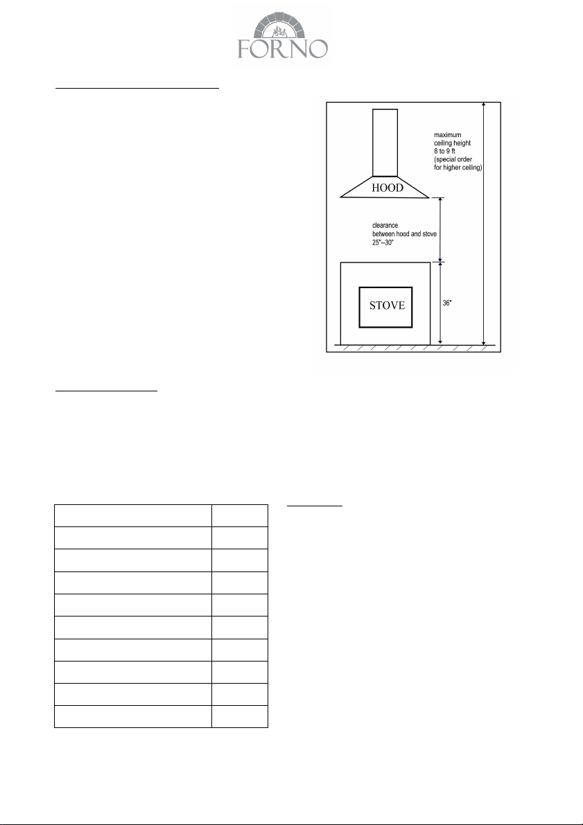
MOUNT HEIGHTS & CLEARANCE
Minimum mount height between range top to hood
bottom should be no less than 25”
Maximum mount height should be no higher than 30”
It is important to install the hood at the proper
mounting height. Hoods mounted too low could result
in heat damage and fire hazard; while hoods
mounted too high will be hard to reach and will loose
its performance and efficiency.
If available, also refer range manufacturer’s height
clearance requirements and recommended hood
mounting height above range.
* Maximum ceiling clearance 106.5” at 27.5” hood
mounting height from stove (different models may
varies)
** For higher ceiling, extension of the chimney and
the decorative cover is available to purchase, if
require.
Ducting (not provided)
NEVER exhaust air or terminate duct work into spaces between walls, crawl spaces, ceiling, attics or garages.
All exhaust must be ducted to the outside.
Use Metal ductwork only.
Fasten all connections with sheet metal screws and tape all joints w/ certified Silver Tape or Duct Tape.
Duct Run Calculation:
Maximum run 6” or 3-1/4 x 10” duct 100FT
Deduct:
each 90 Elbow used 15FT
each 45 Elbow used 9FT
each 6” to 3/14 x 10” 1FT
transition used
each 3/14 x 10” to 6” 5FT
transition used
Side Wall Cap w/ damper 30FT
Roof Cap 30FT
e.g. – 1 roof cap, 2x90 elbows, 1x45 elbow
= 30’ + 30’ + 9’=69’ used,
DUCT SIZE
A minimum of 6” round duct must be used to
maintain maximum airflow efficiency.
Flexible ducts are provided for convenience, always
use rigid type metal ducts if available to maximizing
airflow.
Also use calculation (on left) to compute total
available duct run when using elbows, transitions
and caps.
ALWAYS, when possible, reduce the number or
transitions and turns. If required a long duct
increase duct size from 6” to 7 or 8”.
If a reducer is used, install a long reducer instead of
pancake reducer. Reduce duct size as far away
from opening as possible.
If turns or transitions are required: Install as far away
from opening and as far apart, between 2, as
possible.
31’ available for straight duct runs
MOUNTING THE RANGE HOOD
Note 1 : On stainless steel hoods, carefully remove the plastic protective film from all exterior surfaces
of the hood and chimney prior to final installation.
Note 2: At least two people will be required to mount the hood.
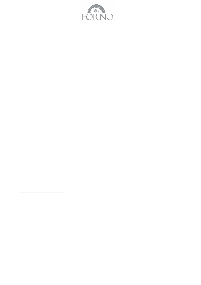
WALL DRILLING AND BRACKETS FIXIN G
1. Draw a vertical line on the supporting wall up to the ceiling, or as high as practical, at the centre of
the area in which the hood will be installed.
2. Draw a horizontal line at desired height (min 25” above the electric hob or 30” above the gas hob).
3. Place chimney mounting brackets on the wall 1/8“ from the ceiling or upper limit aligning t
centre with the vertical reference line.
4. Mark the wall at the centre of the holes in the bracket.
5. Place the hood on the wall with the center to the vertical reference line and make sure the bottom
part of the hood align with the horizontal line.
6. Mark the wall at the centre of the holes in the hood
7. Fix the bracket and hood using the mounting screws
MOUNTING THE HOOD BODY
1. Hook the body onto the screws in the wall
2. Balance the hood body by slightly adjusting the hood mounting screws
he
DAMPER (FLAPS) FIXING
1. Fix the damper (flaps) into the air outlet adapter.
2. To be su r e t h at th e da m pe r ( f la p s) i s l oc k ed w el l o n th e ai r o u tl e t a da p te r, i t s ho u ld b e f le x ib l e i n
opening and closing.
DUCT FIXING
Caution: To reduce the risk of fire, use metal ductwork only.
1. Attach an adequate length of φ 6” round duct into the recessed area of the air outlet adapter.
2. Secure the duct connected with the air outlet adapter by using duct tape to seal the joints

CONNECTIONS
Ducted mode air exhaust system
Caution: To reduce the risk of fire, use metal ductwork is preferred.
1. Decide where the ductwork will run between the hood and the
outside.
2. A stra ight, short duct run will allow the hood to perfor m mos t
efficiently.
3. Long duct runs, elbows, and transitions will reduce the
performance of the hood. Use as few of them as possible.
Larger ducting may be required for best performance wit
h
longer duct runs.
4. Attach an adequate length of φ 6” round duct to the air outlet adapter.
5. The air must not be discharge into a flue that is used for exhausting fumes from appliances
burning gas or other fuels" "Regulations concerning the discharge of air have to be fulfilled.
6. Install a roof/wall cap. Connect round metal ductwork to cap and work back towards hood location.
Use duct tape to seal the joints between ductwork sections.
The regular vent of this range hood is top vent,c
ustomer c
1. Remove motor from top of body by four screws.
2. Remove s
quare metal
plate from back of body by four screws
an choose rear vent as per below steps:
3. Cover the outlet hole at top of body by square metal plate
.
4. Install motor at the back of body by four screws
5. Install square outlet(3-1/4x
10 inch hole) at the back of body by eight screws
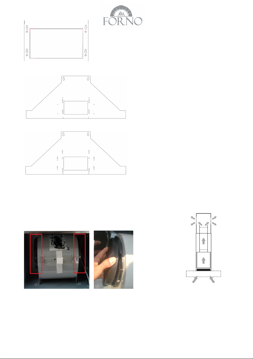
Recirculation Mode(customer need buy charcoal filter separately) Caution:
Do not use plastic or rigid metal ducting.
1. Install charcoal filter on the two side of motor
2. Please note that the air will flow out from the two grids on the sides of the decorative chimney top.
Electrical Connection
* Electrical wiring must be done by a qualified person(s) in accordance with all applicable codes and
sta
ndards.
 Loading...