

Forno FCTGS5738-36, FCTGS5738-30 User Manual
Model:FCTGS5738-36 / FCTGS5738-30
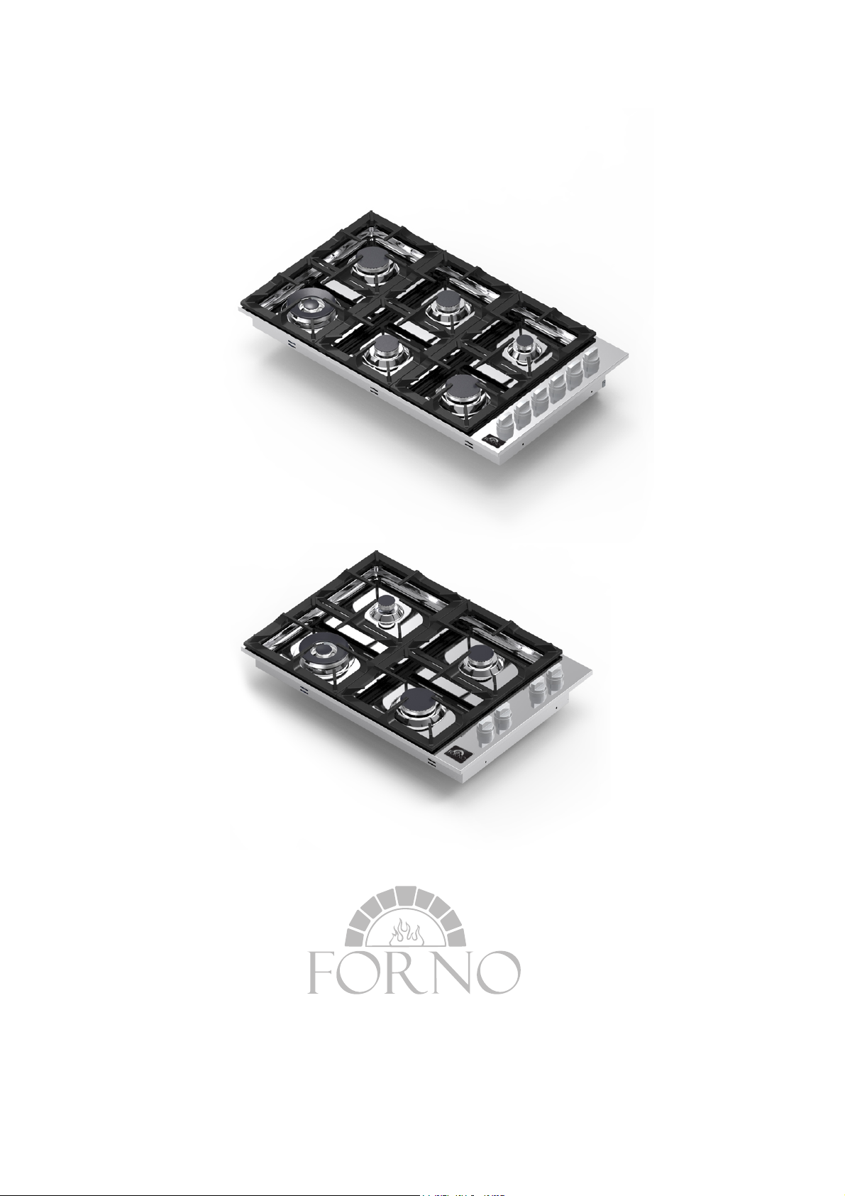
Cooktop
Install Use & Care Guide

IMPORTANT SAFETY
INSTRUCTIONS
If the information in this manual is not followed exactly, a fire
or explosion may result causing property damage, personal
injury or death.
Do not store or use gasoline or other flammable vapors and
liquid in the vicinity of this or any other appliance.
WHAT TO DO IF YOU SMELL GAS
- Do not try to light any appliance.
- Do not touch any electrical switch.
- Do not use any phone in your building.
- Immediately call your gas supplier from a neighbor’s phone.
Follow the gas supplier’s instructions.
- If you cannot reach your gas suppliers, call the fire department.
Installation and service must be performed by a qualified
installer, service agency or the gas supplier
.
!
WARNING
IMPORTANT:
SAVE FOR LOCAL ELECTRICAL INSPECTOR’S USE.
READ AND SAVE THESE INSTRUCTIONS FOR FUTURE
REFERENCE. OBSERVE ALL GOVERNING CODES AND
ORDINANCES.
The manufacturer will not be responsible for any damage to
property or to persons caused by incorrect installation or improper
use of the appliance.
The manufacturer reserves the right to make changes to its
products when considered necessary and useful, without affecting
the essential safety and operating characteristics.
This appliance has been designed for non-professional, domestic
use only.

IMPORTANT SAFETY INSTRUCTIONS —————— 2
INSTALL GUIDE ——————4
USE GUIDE ——————12
CARE GUIDE ——————15
TABLE OF CONTENTS
Thank you for purchasing the our Cooktop unit. Please read the entire
instruction manual prior to using your unit.
You can download an owner's&installation manual at: www.forno.ca.
Customer service : 1-866-231-8893
Fill out the following informa tion for future reference
Brand
Purchase Date
Model Number
Serial Number

This appliance shall only be installed by an authorized person.
This appliance shall be installed in accordance with the manufacturers
installation instructions,
IMPORTANT: this appliance must be installed in accordance with the
norms in force of the country concerned.
The installation of this appliance must conform to local codes and
ordinances. In the absence of local codes, Installations must conforms
to American National Standards, National Fuel Gas Code
ANSI Z223.1 – latest edition** or B149.1.
If local codes permit, a flexible metal appliance connection with the
new AGA or CGA certified design, max. 5 feet (1,5 m) long, 1⁄2” I.D.
recommended for connecting this cooktop to the gas supply line.
Do not bend or damage the flexible connector when moving the
cooktop. The pressure regulator has 1⁄2” female pipe thread.
You will need to determine the fitting required, depending on the
size of your gas supply line, the flexible metal connector and the
shutoff valve.
The appliance, when installed, must be electrically grounded in
accordance with local codes or, in the absence of local codes,
with the National Electrical Code, ANSI/NFPA 70.
The appliance and its individual shutoff valve must be disconnected
from the gas supply piping system any pressure testing of that system
at test pressure in excess of 1⁄2 psi (3,5 kPa).
The appliance must be isolated from the gas supply piping system by
closing its individual manual shutoff valve during any pressure testing
of the gas supply piping system at test pressures equal to or less than
1⁄2 psi (3.5 kPa).
For use with a pressure regulator. The regulator supplied must be
used with this appliance.
The gas appliance pressure regulator must be set for the gas with
which the appliance is used.
INSTALL GUIDE

INST
ALL GUIDE
This appliance can be used with Natural Gas and LP Gas. It is
shipped from the factory adjusted for use with Natural Gas:
CONVERSION FIXED ORIFICES ARE LOCATEDIN THE LITERATURE
PACK SUPPLIED WITH THE UNIT.
Injectors kit for the change of type of gas are contained inside the
package jointly with the hob installation kit and Instruction booklet.
The maximum inlet gas supply pressure incoming to the gas
appliance pressure regulator is 20’’ water column (5 kPa)
The minimum gas supply pressure for checking the regulator setting
shall be at least 1“ w.c. (249 Pa) above the inlet specified manifold
pressure to the appliance (this operating pressure is
4” w.c. (1.00 kPa) for Natural Gas and 10” w.c. (2.75 kPa) for LP Gas).
ATTENTION: A manual valve shall be installed in an accessible
location in the gas line external to the appliance for the purpose of
turning on or shutting off gas to the appliance
WARNING: Do not use aerosol sprays in the vicinity of this appliance
while it is in operation
Inserting the hotplate
After having removed the various loose parts from the internal and
external packing, make sure that the hotplate in not damaged and is
suitable for the specific gas usage. The gas type label is on the
underside of the hotplate base.
In case of doubt, do not use the appliance and contact skilled
personnel.
Keep all the packing parts (polystyrene foam, cardboard, staples, etc.)
away from children.
Consider the critical dimensions of the appliance, before making an
opening in the top surface of the bench top. (relative measurements
as per Fig 1- 2).

Attaching the hotplate
To prevent liquids from leaking accidentally into the underlying
storage space, the appliance is equipped with a special gasket.
To apply this gasket, carefully follow the instructions in Fig. 3. Lay
out the protective sealing strips along the edges of the opening in
the bench top and carefully overlap the strip end. (See Fig. 3). insert
the hotplate into the bench top opening. With a screwdriver assemble
the brackets A to the hotplate bottom by means of the screws B.
(See Fig. 4). Slide the hooks into position and secure them with the
screws.Trim the part of the sealing strips which extend beyond the
hotplate base
Gas connection
Before connecting the appliance to the gas supply, first remove the
plastic plug on which is press- fitted into the gas inlet union; to
remove, just pull it off.
1. Check the ‘gas type’ sticker attached to the hotplate. Details of the
injector sizes used are recorded on the data plate located on the
base of the appliance.
2. This appliance shall be installed in accordance with installation
requirements of the local gas authority of the appropriate
installation code.
3. Before installing the hotplate consider the location of the gas
supply and routing the gas line.(Refer fig.6)
4. For LPG models the gas supply is connected to the regulator
which is supplied loose. The inlet connection has a 1/2” B.S.P.
male thread. IT IS ESSENTIAL THAT THE ELBOW ON THE
APPLIANCE BE HELD FIRMLY WITH A SPANNER WHEN
CONNECTING THE SUPPLY. DO NOT OVER TIGHTEN.
The regulated pressure For LPG is 10” w.c. (See Fig. 5).
INSTALL
GUIDE
 Loading...