

FORNI FEM207SC, FEM107SC, FEM67SC, FEM207, FEM107 Installation, Operation And Maintenance Instructions
...Page 1

- 1 -
LAST REVISION: 27/06/00 IMFOC 00201
INSTALLATION, OPERATION AND
MAINTENANCE INSTRUCTIONS
ANALOGUEELECTRIC-ELECTRONIC“COMBINED”OVEN
In accordance with standards EN 60335 part I
EN 60335 part II - 42
FEM67
FEM107
FEM207
FEM67SC
FEM107SC
FEM207SC
Page 2

- 2 -
CONTENTS
SECTION DESCRIPTION PAGE
1. Warnings ............................................................................................................................................ 3
1.1 General warnings ............................................................................................................................... 3
2. Technical data ................................................................................................................................... 4
2.1 Electrical equipment ......................................................................................................................... 4
3. Installation diagrams ......................................................................................................................... 5
3.1 “Combined” electric oven FEM67/FEM67SC ................................................................................. 5
3.2 “Combined” electric oven with cabinet SFA - SFR U........................................................................ 7
3.3 “Combined” electric oven with stand SF...................................................................................... .... 8
3.4 “Combined” electric oven FEM207/FEM207SC with stand SF2 .................................................... 9
4. Installation instructions .................................................................................................................... 10
4.1 Preparing for installation .................................................................................................. ................. 10
4.1.1 Laws, regulations and technical directives ....................................................................................... 10
4.2 Positioning ........................................................................................................................................ 1 0
4.3 Cold water connection ...................................................................................................................... 1 0
4.4 Waste water outlet ............................................................................................................................. 11
4.5 Electrical connection ........................................................................................................................ 1 1
4.5.1 Earthing ............................................................................................................................................. 11
4.5.2 Equipotential system ......................................................................................................................... 11
4.5.3 Power supply cable........................................................................................................ .................... 11
4.5.4 Transformation to operate with different electric power distribution networks ............................... 1 2
4.6 Other outlets ............................................................................................................... ....................... 1 3
4.7 Room ventilation .............................................................................................................................. 13
4.8 Presenting the oven to the user ......................................................................................................... 13
5. Use ..................................................................................................................................................... 1 3
5.1 User instructions: commissioning..................................................................................................... 1 3
6. Using the electronic oven ................................................................................................................. 15
6.1 Cooking selection ............................................................................................................................. 15
6.2 Vent valve in cooking chamber ........................................................................................................ 1 5
6.3 Humidifier ......................................................................................................................................... 1 6
6.4 Chamber light .................................................................................................................................... 16
6.5 Fan speed ........................................................................................................................................... 16
6.6 Cooking chamber temperature .......................................................................................................... 1 6
6.7 Cooking time and starting the oven ................................................................................................. 1 6
6.8 Core probe ......................................................................................................................................... 17
6.9 Cook & Hold ..................................................................................................................................... 1 7
6.10 Displaying and modifying cooking parameters ............................................................................... 1 7
6.11 Draining the boiler ............................................................................................................................ 1 8
6.12 Messages and alarms ......................................................................................................................... 18
7. Cleaning and maintenance ................................................................................................................ 1 9
7.1 Cleaning ............................................................................................................................................ 1 9
7.1.1 Cleaning after cooking and at the end of the day............................................................................. 1 9
7.1.2 Descaling the boiler ...................................................................................................... .................... 1 9
7.1.3 Troubleshooting................................................................................................................................19
7.2 Maintenance ...................................................................................................................................... 20
7.2.1 Replacing components ...................................................................................................................... 20
A) Electric components and electronic card ..................................................................................... 20
B) Resistor ......................................................................................................................................... 20
C) Oven lamp..................................................................................................................................... 20
D) Oven door gasket.......................................................................................................................... 20
E) Cleaning solenoid valve filters .................................................................................................... 2 0
7.2.2 Yearly maintenance ........................................................................................................................... 21
7.2.3 Safety devices Equipment control and safety systems .................................................................... 22
7.3 Switching off in the event of equipment faults................................................................................. 22
7.3.1 Precautions if the oven is not to be used for a lengthy period.......................................................... 22
Page 3

- 3 -
1. WARNINGS
- Installation, start-up and maintenance of the oven are to be carried out only by skilled personnel authorized by our firm or
by licensed installers.
- Read the instructions contained in this manual carefully as they provide important information on the correct installation,
operation and maintenance procedures.
- Store this manual carefully for future reference by the operators.
- After removing the packing, check the integrity of the equipment.
- In the event of equipment failure or trouble, do not operate the equipment, call professionally qualified personnel.
- Packaging elements (plastic bags, polystyrene foam, nails, etc.) are potentially dangerous and should not be left within the
reach of children.
- Before connecting the equipment, make sure that the data reported on the plate correspond to those of the electric and water
supply networks.
- The plate is located on the front lower right side.
- The equipment is to be operated by specifically trained staff only.
- This equipment must only be used for the purposes for which it was designed, i.e. cooking or warming up food; any other use
is to be considered improper and therefore dangerous.
- Do not obstruct air vents or heat dissipation openings.
- Switch off the oven after use.
The manufacturer disclaims all responsibility for any inaccuracies in this booklet that may be due to typing or printing
mistakes. The manufacturer, moreover, reserves the right to make the modifications to the product it considers useful or
necessary, without affecting its basic features.
In the event of the user or the installation technician failing to observe the instructions given in this manual, the Firm
disclaims all responsibility thereof and cannot be held liable for any accidents or trouble caused by such non-observance.
1.1 GENERAL WARNINGS
Page 4

- 4 -
2. TECHNICAL DATA
2.1 ELECTRIC APPLIANCES
•) With 3N AC 400 V 50 Hz. N.B. With 3N AC 380 V 50 Hz. the thermal power drawn is approximately 9% lower.
With 3N AC 415 V 50 Hz. the thermal power drawn is approximately 9% higher.
MODEL
Standards
Outside dimensions
Width
Depth
Height
Height
Net weight
Cooking chamber dimensions
Width
Depth
Height
Useful volume
Capacity No. Grilles GN 1/1-2/1
Oven load capacity
Guide c/c distance GN 1/1
Tray depth
Power supply voltage
3N AC 380....415 V 50 Hz (or 60 Hz)
External residual
current device
Total absorbed electric power Motor
absorbed electric power
Convection absorbed electric power
Boiler absorbed electric power
Power supply
Power supply cable type H07RN-F
Cable no. 5 wires Cross-section
Water supply
Softened water
Consumption
Steam generation
Steam elimination
* NB : 1 bar = 100 kpa
Waste water outlet
Max. temperature
Oven performance
Hot air temperature range
Steam temperature range
Core probe temperature range
Time to reach 180-215°C
Consumption to keep average 215°C
Fan speed
mm
mm
min.mm
max.mm
kg
mm
mm
mm
dm
3
max.kg
mm
min.mm
A/ph.
kW
kW
kW
kW
min.mm
2
(min÷max)bar*
l/h
l/h
Ø mm
max.°C
°C
°C
°C
min.
kWh
min.g/min
max.g/min
EN 60335 -I
EN 60335 - II - 42
FEM67
FEM67SC
FEM107
FEM107SC
FEM207
FEM207SC
940
850
805
855
120
640
420
430
129
6/-
18÷24
60
20
x
16
9,5
0.5
9.0
6.0
1.5
G 3/4”
0.5÷4
9
90
40
100
20÷270
20÷100
20÷99
4/5.0
1,2
1400
2800
940
900
1050
1100
175
640
420
670
199
10/-
30÷40
60
20
x
32
15.6
0.6
15.0
12.0
2.5
G 3/4”
0.5÷4
18
140
40
100
20÷270
20÷100
20÷99
3.5/4
1,4
700
1400
1340
980
1045
1095
330
640
860
670
322
20/10
60÷80
60
20
x
40
22.3
0.7
21.6
15.0
6.0
(2X) G 3/4”
0.5÷4
22
140
40
100
20÷270
20÷100
20÷99
5.5/6
1.8
700
1400
Page 5
- 5 -
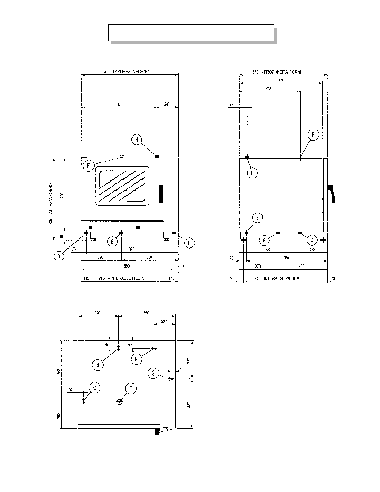
3. INSTALLATION DIAGRAMS
3.1 “COMBINED” ELECTRIC OVEN FEM067/FEM67SC
D) Water outlet Ø 40 mm
F) Vent pipe Ø 50 mm
G) Power supply cable entry
B) Softened water inlet G 3/4”
H) Descaling agent inlet
Page 6
- 6 -
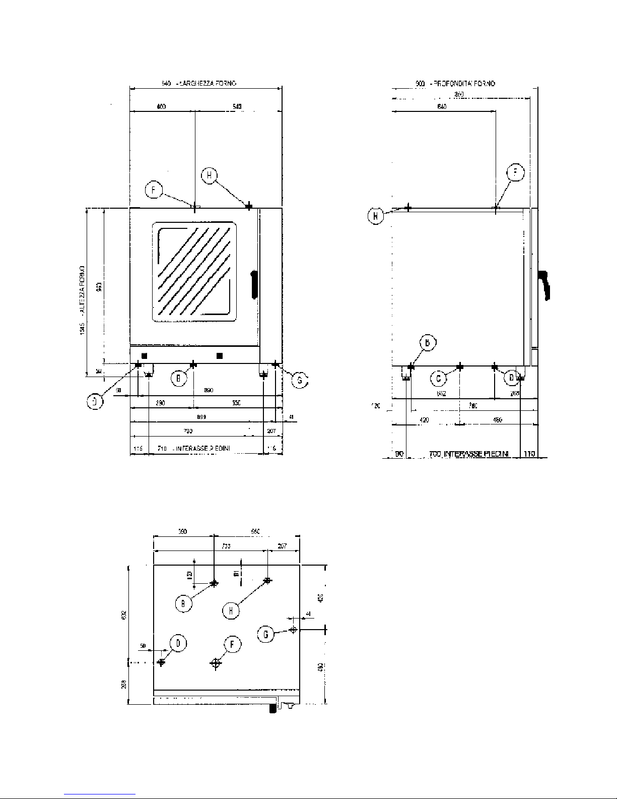
“COMBINED” ELECTRIC OVEN FEM107/FEM107SC
D) Water outlet Ø 30 mm
F) Vent pipe Ø 40 mm
G) Power supply cable entry
B) Softened water inlet G 3/4”
H) Descaling agent inlet/
Safety valve
Page 7
- 7 -
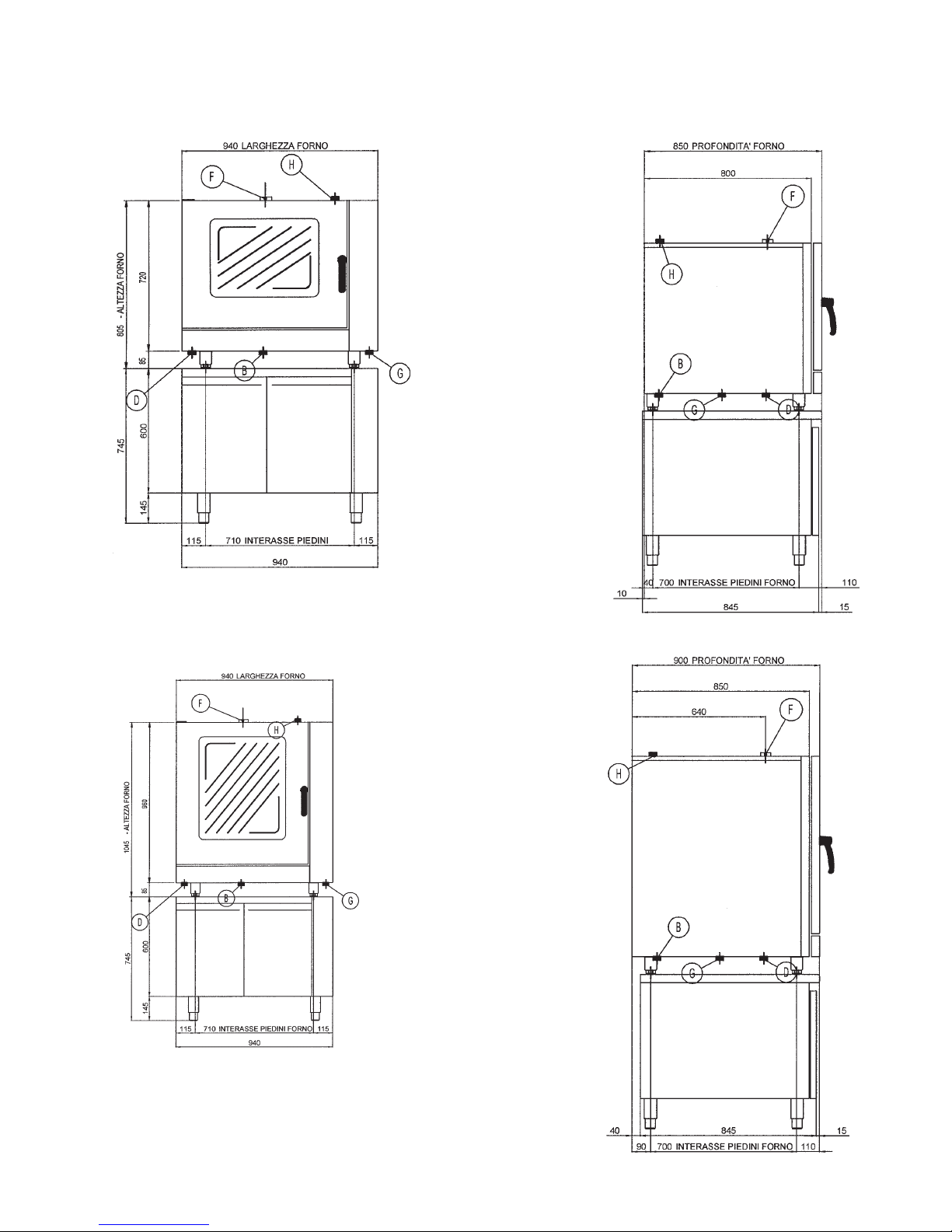
3.2 “COMBINED” ELECTRIC OVEN WITH CABINET SFA - SFRU
FEM67
FEM67SC
FEM107
FEM107SC
D) Water outlet Ø 40 mm
F) Vent pipe Ø 50 mm
G) Power supply cable entry
B) Softened water inlet G 3/4”
H) Descaling agent inlet
D) Water outlet Ø 30 mm
F) Vent pipe Ø 40 mm
G) Power supply cable entry
B) Softened water inlet G 3/4”
H) Descaling agent inlet/Safety valve
Page 8
- 8 -
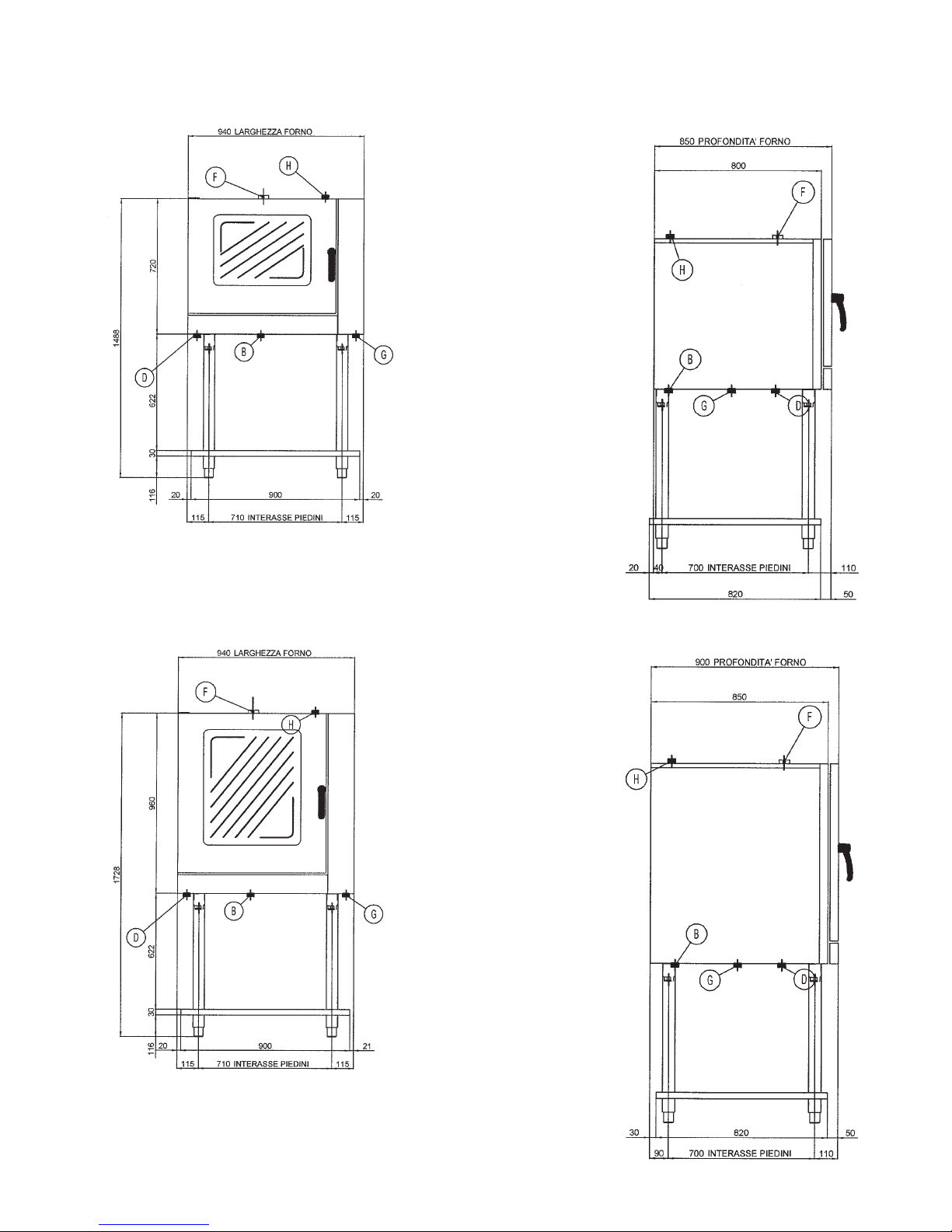
3.3 “COMBINED” ELECTRIC OVEN WITH MOUNTING SF
FEM67
FEM67SC
FEM107
FEM107SC
D) Water outlet Ø 40 mm
F) Vent pipe Ø 50 mm
G) Power supply cable entry
B) Softened water inlet G 3/4”
H) Descaling agent inlet
D) Water outlet Ø 30 mm
F) Vent pipe Ø 40 mm
G) Power supply cable entry
B) Softened water inlet G 3/4”
H) Descaling agent inlet/Safety valve
Page 9
- 9 -
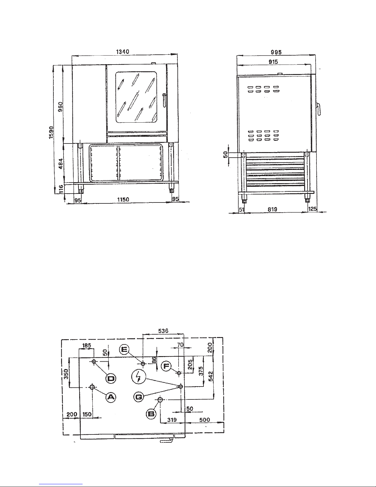
3.4 “COMBINED” ELECTRIC OVEN FEM207/FEM207SC WITH MOUNTING SF2
D) Humidifier water inlet
and steam generator G 3/4”
E) W ater outlet Ø 40 mm
F) Cold water inlet
eliminating steam G 3/4”
B) Top steam outlet
adjustable Ø 50 mm
G) Power supply cable entry
A) Steam generator weight valve
(descaling agent inlet)
Page 10
- 10 -
4. INSTALLATION INSTRUCTIONS
Installation and adjustment operations are to be carried out by qualified personnel according to the norms in force.
(See technical specification tables page 4).
WARNINGS:
- If the oven is installed against a wall, the wall needs to withstand temperatures of 80°C and must be incombustible.
- Inlets (water and electricity) and outlets (waste water, steam etc.) are signalled by dedicated tags.
- The top of the oven is not to be used to store goods!
4.1 PREPARING FOR INSTALLATION
Before proceeding to installation, remove the protective plastic film and eliminate any adhesive residues by means of a suitable
product for cleaning stainless steel.
4.1.1 LAWS, REGULATIONS AND TECHNICAL DIRECTIVES
The following regulations must be observed during installation:
- Current accident-prevention regulations.
- ”Electric system installation” standards.
- The regulations of the electricity board.
- The regulations of the water board.
- Local ”municipal” norms on the drainage of waste water.
- Health regulations.
- Italian law no.46 05/03/1990.
4.2 POSITIONING
Place the oven under a ventilation hood to make sure all vapours are extracted.
Install the oven horizontally and check the correct positioning by means of a level; rotate levelling feet to adjust.
The oven may be installed on its own or in a group of several elements; but make sure it is not placed next to combustible
objects.
- Never obstruct the air vents and heat dissipation openings of the oven.
- The electric cable must never be subject to traction.
- Provide clearance of 1/2 metre on the right for maintenance.
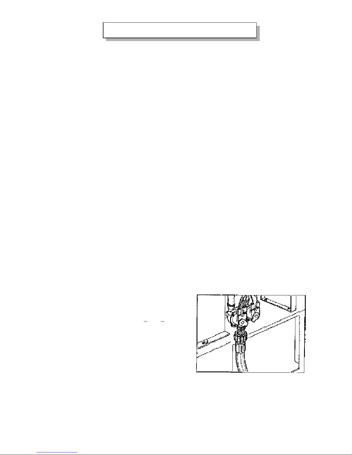
4.3 COLD WATER CONNECTION
(SOFTENED)
Water pressure: min. 50 kPa max. 400 kPa (0.5 < PH2O < 4 bar).
The water inlets must be connected to the softened supply
network at a maximum temperature of 50°C by means of
shut-off valves, to be closed when the oven
is not being used or for maintenance work.
The water is used to condense the vapours in the
waste water outlet, to supply the humidifier and
to generate steam; between the shut-off valve and
the oven connection pipe, there must be a mechanical
filter so as to prevent any ferrous waste getting
inside that could over time cause oxidation of the
oven.
If the hardness of the water is greater than 5-7°Fr, it is
necessary to install a softener with automatic
regeneration, to be positioned after the mechanical filter.
As regards the flow rate per hour of the softener, refer to the Table on page 4.
REAR WATER
CONNECTION
Page 11
- 11 -
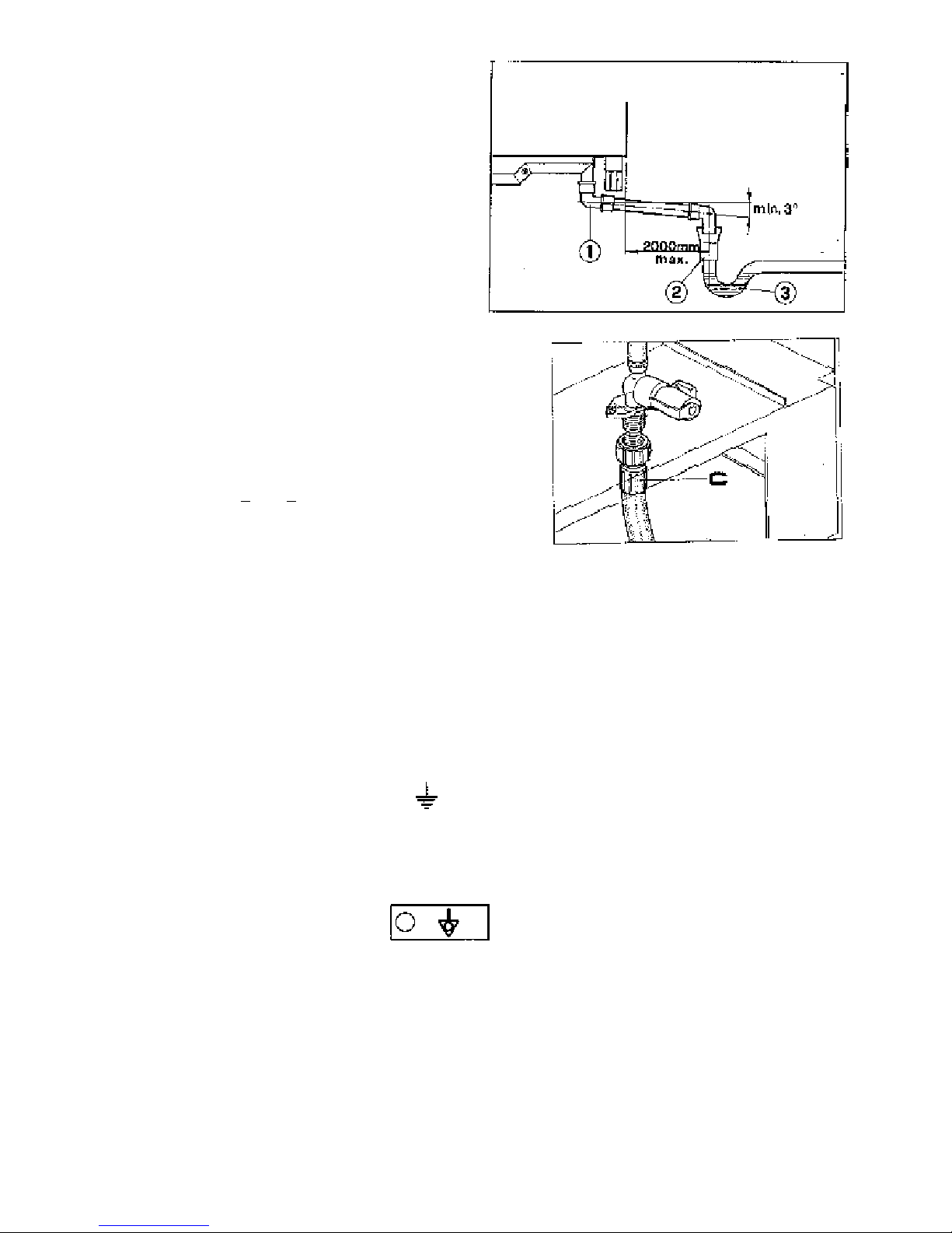
4.4 WASTE WATER OUTLET
The water outlet “1” must lead
to an open siphon “2” so as
to allow no contact between the outlet pipe
of the oven and the collecting siphon
as per the current local health regulations
and for the oven to work properly.
To prevent bad smells and waste water getting
back into the oven, after the open siphon there
should be a normal siphon “3”.
The drain pipe is to be manufactured
with materials able to withstand temperatures
of 100°C.
N.B. A “closed” connection to the channel
is not permitted!
To condense outlet vapours of the oven FEM207/FEM207SC
connect cold water supply to the solenoid valve C as
shown in the figure.
The water pressure must be between
50 and 400 kPa (0.5 <
PH 2O < 4 bar).
4.5 ELECTRICAL CONNECTION
- The electrical connection must be carried out by qualified authorized personnel only, in compliance with the regulations in
force. Check the data reported in the technical data Table on page 4 of this manual, on the adhesive connection label on page
11 and in the wiring diagram. The connection envisaged is fixed.
IMPORTANT: A multi-polar mains cut-off device must be provided upstream from each oven, with a contact opening gap of
at least 3 mm.
For example:
- a manual switch of suitable capacity, equipped with fuses
- residual current device.
4.5.1 EARTHING
It is vital to earth the oven.
Connect the terminals marked by the symbols ( ) positioned on the line-in terminal block to an efficient grounding
complying with the regulations in force.
CAUTION: NEVER CUT THE GROUNDING CABLE (yellow-green)
THE MANUFACTURER DISCLAIMS ALL RESPONSIBILITY IF THESE SAFETY STANDARDS ARE NOT
COMPLIED WITH.
4.5.2 EQUIPOTENTIAL SYSTEM
The oven must be included in an equipotential system whose efficiency must be checked according to the
standards in force. The screw marked by the ”Equipotential” label is near the terminal block on the base.
4.5.3 POWER SUPPLY CABLE
The oven is supplied without a power cable. The specifications of the power supply connection flexible
cable must match or be superior to those of the cable with rubber insulation H07RN-F.
As regards the cross-sections of cables, refer to the table on page 11. Introduce the cable through the cable clamp
and secure it firmly. During operation, the power supply voltage should not differ from the voltage rating by +/-10%.
INDIRECT WASTE WATER OUTLET THROUGH
OPEN SIPHON
Page 12
- 12 -
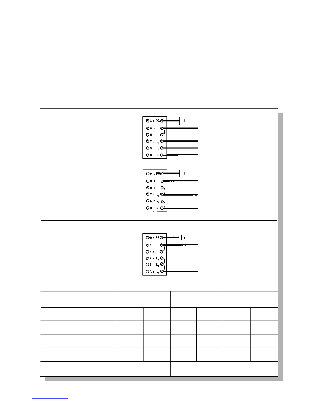
4.5.4 TRANSFORMATION FOR OPERATION WITH DIFFERENT ELECTRICAL
NETWORKS FOR DISTRIBUTION
Equipment is manufactured to operate with the following voltage values: 3N AC 380...415 V; 3 AC 220....240 V or AC 220....240
V 50 Hz. (in case of 60 Hz. power supply, request the appropriate kit).
If it is to be connected to one of these voltages, proceed as follows:
• Remove the right panel.
• Connect the power supply cable to the terminal block according to the mains voltage, following the wiring diagram and the
adhesive connection label placed near the terminal block.
Fasten the cable-clamp firmly after inserting a sufficient length of cable.
CONNECTIONS TO THE DIFFERENT ELECTRICAL NETWORKS
TYPE OF VOLTAGE
3N AC 380...415 V 50 Hz
3 AC 220...240 V 50 Hz
AC 220...240 V 50 Hz
WIRING DIAGRAM
DRAWING No.
15.2
24.5
41.3
I max.
A/f
No. cables
mm
2
MODEL
FEM67
FEM67SC
PE (Earth) yellow-green
N (NP) blue
L
3
(T) black
L
2
(S) black
L
1
(R) brown
3N AC 380...415 V 50 Hz
PE (Earth) yellow-green
L
3
(T) blue
L
2
(S) black
L
1
(R) brown
3 AC 220...240 V 50 Hz
PE (Earth) yellow-green
N (NP) blue
L
1
(R) brown
AC 220...240 V 50 Hz
5 x 1.5
4 x 2.5
3 x 10
FEM107
FEM107SC
11344
FEM207
FEM207SC
11346 12402
I max.
A/f
I max.
A/f
No. cables
mm
2
No. cables
mm
2
5 x 2.5
4 x 6
-
5 x 6
4 x 10
-
24.3
39.9
-
33.0
57.0
-
Page 13

- 13 -
4.6 OTHER OUTLETS
For no reason may the food vapour vent or waste water outlet of the appliance be closed, blocked or channelled together with
other pipes.
4.7 ROOM VENTILATION
It is necessary to have plenty of air coming into the rooms to take the place of the volume of air expelled through the flues,
approximately 30 m
3
/h. Air should be introduced into the room without causing any dangerous draughts or being directed
towards the operators. Adjust the ventilation outlet flaps properly. Regularly clean the intake fan, filters and pipe to prevent the
fans getting clogged. Never use flammable solvents to clean the filters. Periodically check the outlet for any damage or
obstruction.
4.8 PRESENTING THE OVEN TO THE USER
Explain the operation and use of the oven to the user with the aid of the instructions booklet.
Leave the instructions booklet with the user and explain he needs it for further reference.
A technical service and maintenance contract should be recommended for the user.
5.1 USER INSTRUCTIONS: COMMISSIONING
CAUTION: For supervised operation only.
After positioning and connecting the oven, the inside is to be cleaned thoroughly. Spray the inside of the oven with a specific
degreasing product (make sure not to use products that can leave residues that smell in the oven). Select the ”convection”
function, a temperature of 90°C and a humidity of 40%, then operate the oven for 30÷40 minutes. Turn the oven off and dry with
a cloth.
The combined oven belongs to the second generation of convection ovens. It is a convection oven and a pressureless steam oven
combined into one. The steam is generated inside the oven and set in circulation by a powerful fan. Any food can be prepared in
the ideal manner with a single oven. The combined oven may be used every day for any kind of cooking. Thanks to its numerous
features, it can be used for steam cooking, gratinating, stewing, browning, grilling, braising, pre-cooking, reheating and defrosting.
Utilization:
1) CONVECTION OVEN: like a conventional oven, but with the well-known advantage of forced-ventilation.
2) STEAM OVEN pressureless: to steam-cook, defrost and heat.
3) COMBINED: for all foods that need to be cooked very differently without having to change oven.
For example: - steaming and then grilling
- browning and then steaming
- steaming and later gratinating
- cooking and roasting meat, baking bread and pastries
- steaming at 100°C
- second cooking
- slow cooking 50/97°C
- boiling, braising and roasting
- defrosting and warming up
- defrosting, heating and cooking different products at the same time
CAUTION: Never use coarse salt since it would not dissolve completely.
In the long run, undissolved salt can cause corrosion at contact points.
Lower temperatures than static ovens are used, they may be from 20 to 30°C lower depending on the type of food to be cooked.
Two cooking cycles are possible to have different temperatures and humidity levels.
Make sure that the food is placed so as to avoid any modification of the balanced air circulation inside the chamber (max. load
approx. 4 kg/GN 1/1).
The dual speed allows very high performance in the cooking of pastries.
Warning: when the oven is hot, open the door cautiously since the accumulated steam can scald.
Hot surfaces of the oven: door, glass and front.
5. USE
Page 14
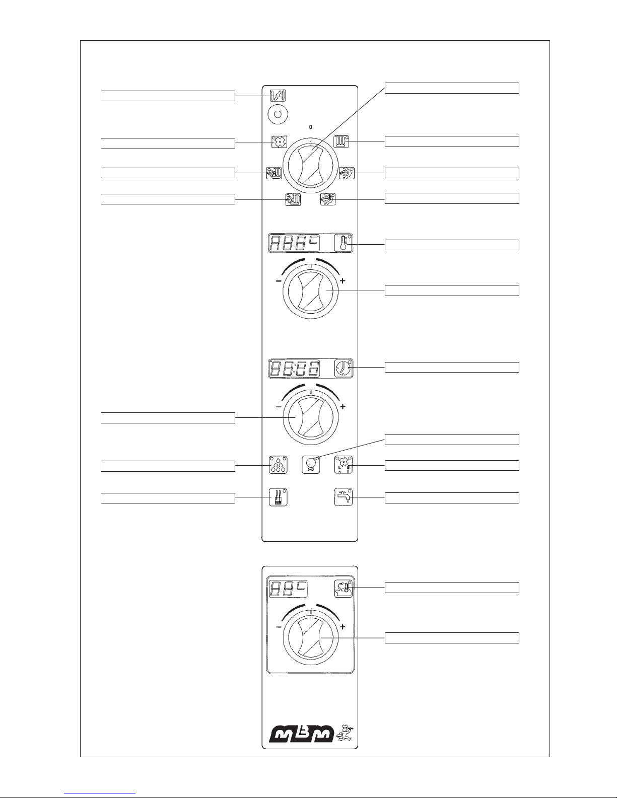
- 14 -
TAB.1
ELECTRONIC COMBINED OVEN INSTRUCTIONS - CONTROL PANEL
- 1 VALVOLA SFIATO -
- 7 RAFFREDDAMENTO CAMERA -
- 6 RIGENERAZIONE -
- 5 MISTO -
- 11 MANOPOLA TIMER -
- 12 UMIDIFICATORE -
- 15 LED SONDE BOILER -
- 16 SCARICO BOILER -
- 17 SONDA CUORE -
- 18 MANOPOLA TEMPERATURA -
- 14 DOPPIA VENTILAZIONE-
- 13 ILLUMINAZIONE CAMERA-
- 10 DISPLAY TIMER -
- 19 MANOPOLA SELETTORE -
- 2 CONVEZIONE -
- 3 VAPORE -
- 4 VAPORE TERMOSTATO -
- 8 DISPLAY TEMP. CAMERA -
- 9 MANOPOLA TEMPERATURA -
Page 15
- 15 -
6. USING THE ELECTRONIC OVEN
6.1 COOKING SELECTION
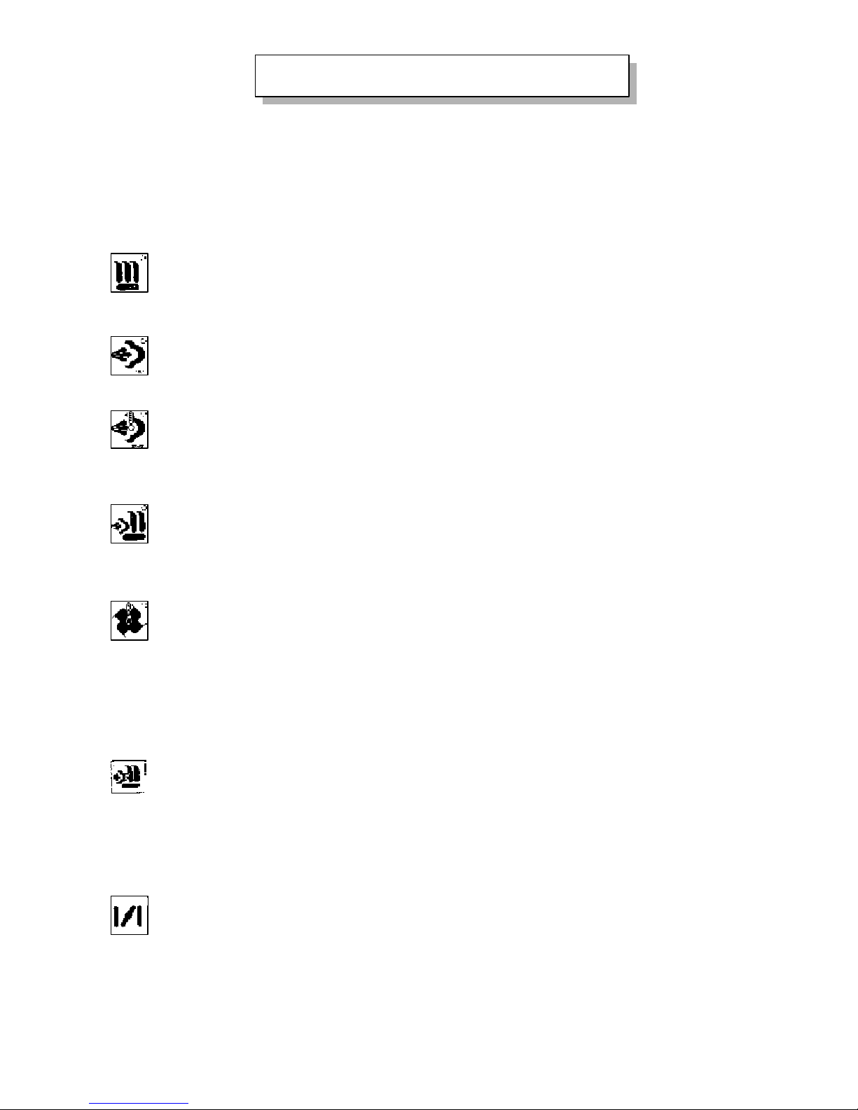
The selection is made by turning the selector onto one of the six positions corresponding to the different cooking modes: the
respective LEDs (2,3,4,5,6,7) flash and, after a few seconds, the function is accepted. The control panel then comes on and the
oven is prepared for cooking: the boiler is loaded and then pre-heating takes place. It is therefore advisable to turn the selector
at least ten minutes before starting cooking in order to have the oven ready.
CONVECTION COOKING
From 20°C to 270°C this is the fastest cooking method. It offers the opportunity of combining different cooking
methods without altering the flavour, thanks to the hot air evenly distributed in the chamber by a fan. Ideal for
roasting, gratinating, toasting and grilling.
STEAMING 100°C
The main advantages of steaming comprise maintaining nutrition values, greater efficiency and lower weight loss,
the possibility of multiple cooking and the considerable savings in sauces.
THERMOSTATTED STEAMING
From 50° to 99°C it permits cooking foods that have already been processed, portioned and vacuum packaged. The
main advantages deriving from using this type of cooking comprise programming and the batching of work, longer
preservation of cooked foods, virtually no weight loss and nutrition values are maintained.
COMBINED COOKING
From 100°C to 270°C this cooking mode combines the benefits of steam and convection. It can cut cooking time
down to 30% even for traditionally difficult foods such as potatoes, carrots, etc. It is possible to steam foods and then
gratinate them, or glaze them or make them crispy. Combined cooking, thanks to the intense humidity and heat of
the air, decreases the weight loss of traditional dishes (roasts, hams, etc.).
AUTOMATICALLY LOWERING OVEN TEMPERATURE
If steaming or thermostatted steaming are selected when the oven is still hot due to previous cooking at high temperature,
water is injected into the oven and steam is not generated so as to quickly lower the temperature and prevent spoiling product
put into a chamber that is too hot.
WARMING
This type of heating makes it both possible and cost-effective to warm up refrigerated products. It is done in
combined mode, 160°C, low speed. It is recommended to keep the vent valve 1 open.
6.2 COOKING CHAMBER VENT VALVE (1)
This lever makes it possible to open and close the cooking chamber vent valve so as to adjust the amount of steam
leaving the cooking chamber.
VENTILATION TO LOWER OVEN TEMPERATURE
This is used to lower the temperature of the cooking chamber quickly. In this function the fan turns also with the
door open: to have this type of operation, close the door, set the ventilation function, proceed by starting the oven,
setting a time, then open the door.
Page 16
- 16 -
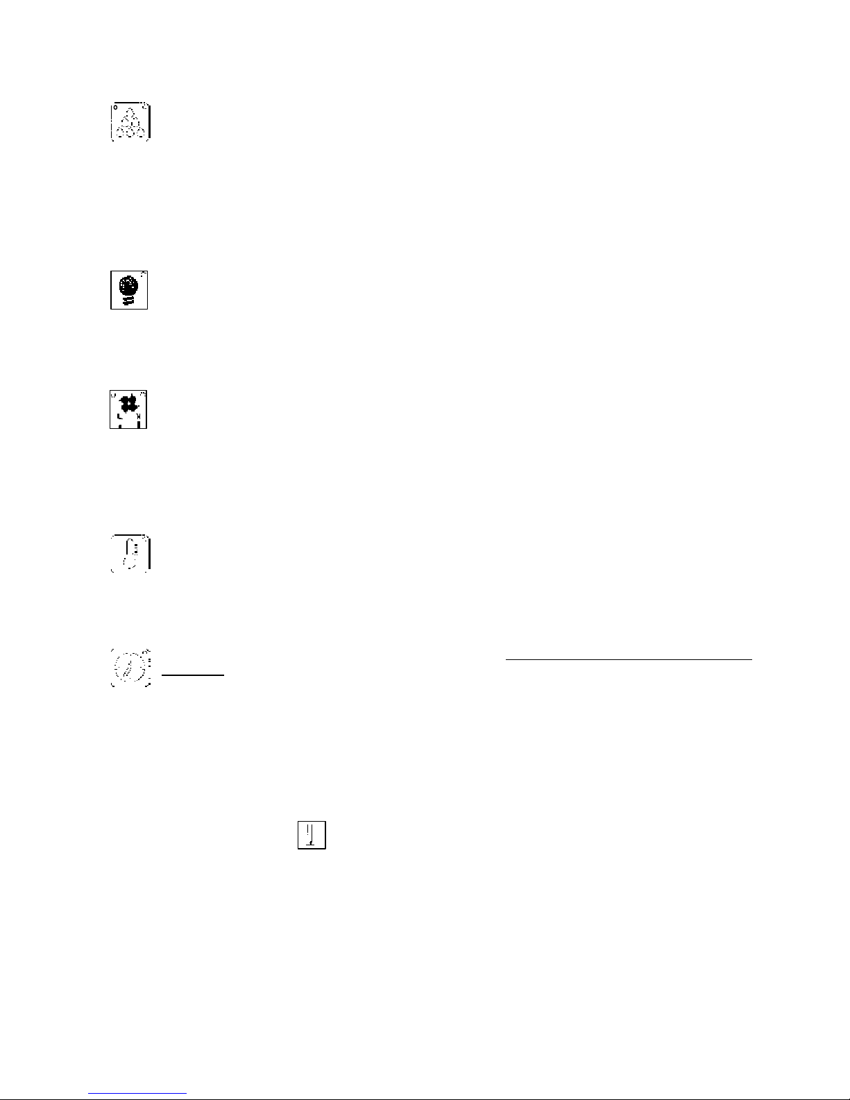
6.4 OVEN LIGHT (13)
6.5 FAN SPEED (14)
Two speeds are available: a high one for fast cooking and a low one for delicate cooking or steaming. The LEDs at the corners
of the button indicate which speed has been selected.
6.6 OVEN TEMPERATURE (8)
6.7 COOKING TIME AND STARTING THE OVEN (10)
During oven operation, the display 10 shows the time passed. On reaching the set value, the oven stops, emits the end-ofcooking sound for 1 min. and displays the message “End”.
To cancel this message (or to terminate before the end-of-cooking sound), in order to set a new cooking time, you need to press
the clock button (10).
In the case of continuous operation, to end cooking you need to zero the cooking time or turn the selector onto Ø.
Pay attention to these points:
1) If steaming, thermostatted steaming, combined cooking or warming are selected, the oven will not start until the boiler has
finished loading, it will stay on standby (in other words as long as LED 16 is on).
2) In the 100°C steam function, the fan will not turn until the chamber reaches 80°C. This makes it possible to put the product
inside even when the oven is closed without having any movements of air that can affect the cooking.
3) The oven is equipped with a cooling fan for the internal components. It starts when the oven is switched on and stops
approximately ten minutes after the oven has stopped working.
Button 13 switches the oven chamber light on or off at any time as preferred.
TWIN FAN SPEED
This function makes it possible to halve the amount of air in the cooking chamber as required for delicate cooking,
which needs less air flow while ensuring homogeneous cooking. This control therefore makes it possible to use a
single oven for two preparations.
After selecting the desired cooking function, display 8 will show a pre-set temperature. To change it you need to
turn knob 9 clockwise to increase, anticlockwise to decrease it.
During oven operation, display 8 shows the temperature in the cooking chamber.
To set a cooking time and start the oven you need to turn knob 11: a few seconds after letting go of the knob, the oven
will start up. Turning the knob clockwise makes it possible to set a cooking time. Whereas, to have continuous
operation you need to turn the knob anticlockwise until the appearance of Cont on the display 10.
6.3 HUMIDIFIER (12)
Caution: In the steaming, thermostatted steaming and combined cooking modes, the humidifier is disabled so it is not possible
to add more water into the chamber when the boiler is already in operation.
It is possible to adjust the percentage of moisture in the cooking chamber. It is essential to obtain products with a
low moisture content, such as bread, biscuits and cakes, soft items.
The humidifier is also used to prevent roasts from burning or losing a lot of their liquid. Pressing this button once
(left LED on) introduces approximately 4 l/h of water. Pressing it again (right LED on) introduces water continuously
(approximately 18 l/h). To switch off the humidifier, press the button again (LEDs off).
Page 17

- 17 -
During operation with the core probe, the minute counter will in any case display the time passed.
The inner probe only stops cooking on reaching the temperature inside the food pre-set on the specific display.
The temperature range that can be adjusted in the display is 20°C - 99°C.
Caution: It is anyhow always necessary to set the temperature and cooking process (e.g. convection, steam, combined or
convection with humidification) in the cooking chamber. If 99°C is exceeded the display will show Ovl (Overflow). At the end of
cooking with the core probe, cook & hold triggers automatically (see par.6.9).
If at the start of cooking the core probe is hot because of pre-heating the oven (when the core probe was in the cooking
chamber), display 18 will flash until the actual temperature of the food is displayed; only then will cooking commence.
To cook with the core probe, first of all turn the selector onto one of the functions. Pressing this push-button will
light up the core probe temperature display, showing a set temperature, and the minute counter display will be
deactivated. Set the desired core temperature with knob 18. A few seconds after letting go of the knob the oven will
start and the temperature inside the food will be displayed.
6.8 CORE PROBE (Only for models -SC)
For many foods (for instance roast-beef, pâté, fatty roasted meat, etc.) the temperature inside the product is very important.
With the inner probe, it is possible to switch off the oven at the right time, that is when the desired temperature (previously set
on display 17) has been reached.
You do not need to set the cooking time because, by setting the temperature on the thermostat of the ”inner probe”, the timer
is automatically excluded.
The thermostat shows the temperature inside the product.
The cooking time is obtained from the ”inner probe” thermostat. You can use the ”inner probe” cooking process together with
all the other cooking processes (for instance, steaming, convection cooking, mixed cooking and so on).
Here is a table giving the temperature to set:
Inner temperature °C Application
40 ÷ 45 Raw meat
45 ÷ 50 Rare meat
50 ÷ 70 Red meat
75 ÷ 95 Well-done meat
- Insert the probe into the most representative piece.
- Place the piece of meat containing the core probe in the geometrical centre of the cooking chamber.
- Make sure that the probe tip is as much in the centre of the piece to be cooked as possible.
6.9 COOK & HOLD
Cook & hold is only activated in the core probe cycle. At the end of cooking, the product is kept hot without its temperature
falling under 70°C and thereby excluding the risk of bacteria spreading.
At the end of cooking with the core probe, the oven automatically goes onto hold, shown on display 10 with the flashing
message Hold. If after ten minutes the oven is not switched off and the product taken out, the holding process shown by the
steady message Hold commences. Pressing the clock button (10) displays the time passed since the start of holding. During
holding the oven automatically heats up if the core temperature falls under 70°C.
To end holding, you need to turn the selector onto Ø.
6.10 DISPLAYING AND MODIFYING COOKING PARAMETERS (8, 10, 17)
DISPLAY: Just press one of the buttons 8, 10, 17 (LED on) and the relevant displays will show the chamber temperature and the
set time or the set core temperature. Wait for a few sec. and the displays will go back to showing the chamber temperature, time
passed or core temperature (LED off).
CHANGE. While the oven is operating, to change the set temperature or time or core temperature, you need to press the relevant
button (LED on) and turn the knob: after a few seconds the new parameter will be accepted (LED off).
Page 18
- 18 -
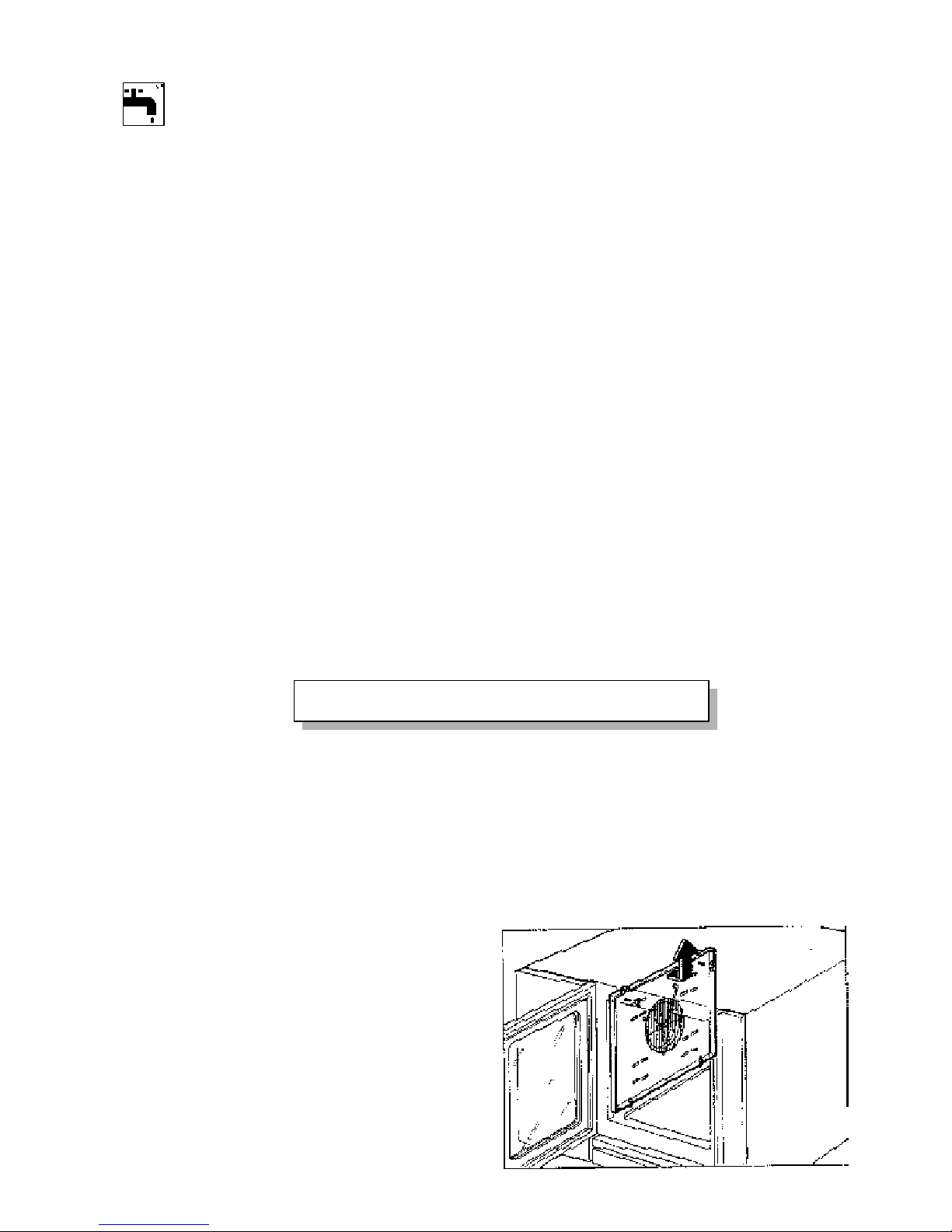
6.11 DRAINING THE BOILER (16)
Caution: After manually draining the boiler you need to switch off the control panel selector on Ø; otherwise, the boiler will
no longer be loaded. Afterwards, switching the control panel back on, turning the selector, the valve will automatically close
and the boiler will start loading.
AUTOMATIC BOILER DRAINING + WASHING
After approximately 5 hours of the oven not working, the boiler is automatically drained and rinsed with a second load and
a second draining.
Caution: For the oven to do this, you need to leave the multi-polar switch on and the water shut-off valves upstream from the
oven open.
6.12 MESSAGES AND ALARMS
Service messages
Door : door open
Cont : continuous operation
Hold flashing: waiting to hold
Hold steady: holding in process
End : cooking has ended.
Alarm messages
H20 : Not enough water in the boiler. See if the water valve is shut or if there is no water in the supply network.
To cancel the message and restart loading the boiler, press the clock button (10).
P1 no : Chamber temperature sensor broken or disconnected.
P2 no : Core probe broken or disconnected (it is still possible to continue using the oven without the core probe).
P3 no : Boiler pre-heating probe disconnected.
IMPORTANT: In the case of the last three messages, it is recommended to call a technician to restore normal conditions.
Button 16 makes it possible to drain the boiler manually (only when the oven is not in operation). When the LED
is on, the valve is open, when it is off, the valve is shut.
7.1 CLEANING
CAUTION:
Never wash the outside of the oven with direct or high-pressure jets of water as this would damage the electric components inside.
The oven needs cleaning every day as a matter of hygiene and to prevent its operation getting impaired over time.
7.1.1 CLEANING AFTER COOKING AND AT THE END OF THE DAY
Use a specific degreasing product to clean the oven (do not use corrosive or chlorine-based detergents). It is recommended to
follow the detergent manufacturer’s directions.
1) Carry out the cleaning program as described in par. 6.5.
2) Then open the oven and wipe it with a damp cloth
or dry it with hot air at 100°C.
3) Take out the filter and the removable parts and wash them
fully open.
4) Rinse the oven and accessories with water, possibly
using the external handshower (optional on all
versions).
5) Dust the door gasket regularly with talcum powder,
at least once a week.
6) See that the outlet is cleaned regularly and
check it is clear.
FEM207-FEM207SC
7. CLEANING AND MAINTENANCE
Page 19
- 19 -
7.1.3 TROUBLESHOOTING
THE OVEN DOES NOT COOK EVENLY
* The products to cook have been pressed too close to each other.
You should always check there is good air circulation between the products.
YOUR PRODUCT IS DRY AND IS UNFIT FOR CONSUMPTION
* Check whether the humidifier is working and whether the temperature is the right one for your product.
7.2 MAINTENANCE
Before doing any maintenance work you must cut off the electricity and water supplies to the oven.
All the oven components, being subject to wear, are easy to reach from the right-hand side.
7.2.1 REPLACING COMPONENTS
CAUTION: Have this done by a skilled technician only!
Disconnect the electricity and water supplies.
Follow the wiring diagram.
A) Electric components and electronic card
All the electric components and the electronic card are on the right-hand side of the oven.
In order to replace them, you therefore need to take off the right-hand side panel.
This is why the oven should be installed with sufficient clearance on the right-hand side.
B) Resistor
To replace the resistor:
- Remove the rear panel.
- Open the screen inside the oven.
- Detach all the wires.
- Remove the resistors.
- Fit it all back together in reverse order to the above
and using the wiring diagram.
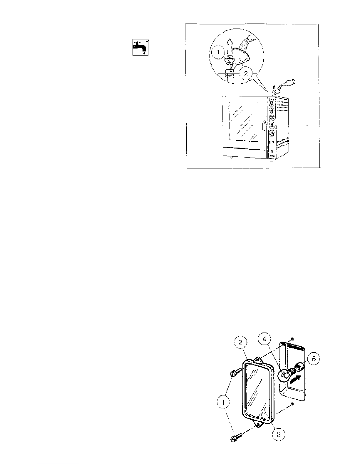
C) Oven lamp Tab.3
- Remove both screws (1).
- Remove the frame (2) with glass (3).
N.B. Check that the silicone rubber gasket is not damaged.
- Replace the oven lamp (4).
- Fit it all back together in reverse order to the above.
7.1.2 DESCALING THE BOILER
Every 7 - 15 days it is advisable to carry out descaling.
- Drain the boiler by pressing the
button then close it again.
- Prepare a solution of descaling liquid following
the manufacturer’s directions.
Quantity of diluted solution:
FEM67 = 4 l
FEM107 = 5.5 l
FEM207 = 5.5 l
- Lift the cap 1 (Tab.7) and pour the solution into the boiler.
- Operate the oven with the steam function for approximately
2-3 minutes to pre-heat the solution.
- Let the liquid act approximately 10' then drain the generator.
- Switch the control panel off and back on again by turning the
selector so as to load the boiler. When loaded, drain it again.
N.B. For the steam generator to function properly
the water softener requires thorough maintenance
in order to avoid scale.
TAB. 7
Page 20
- 20 -
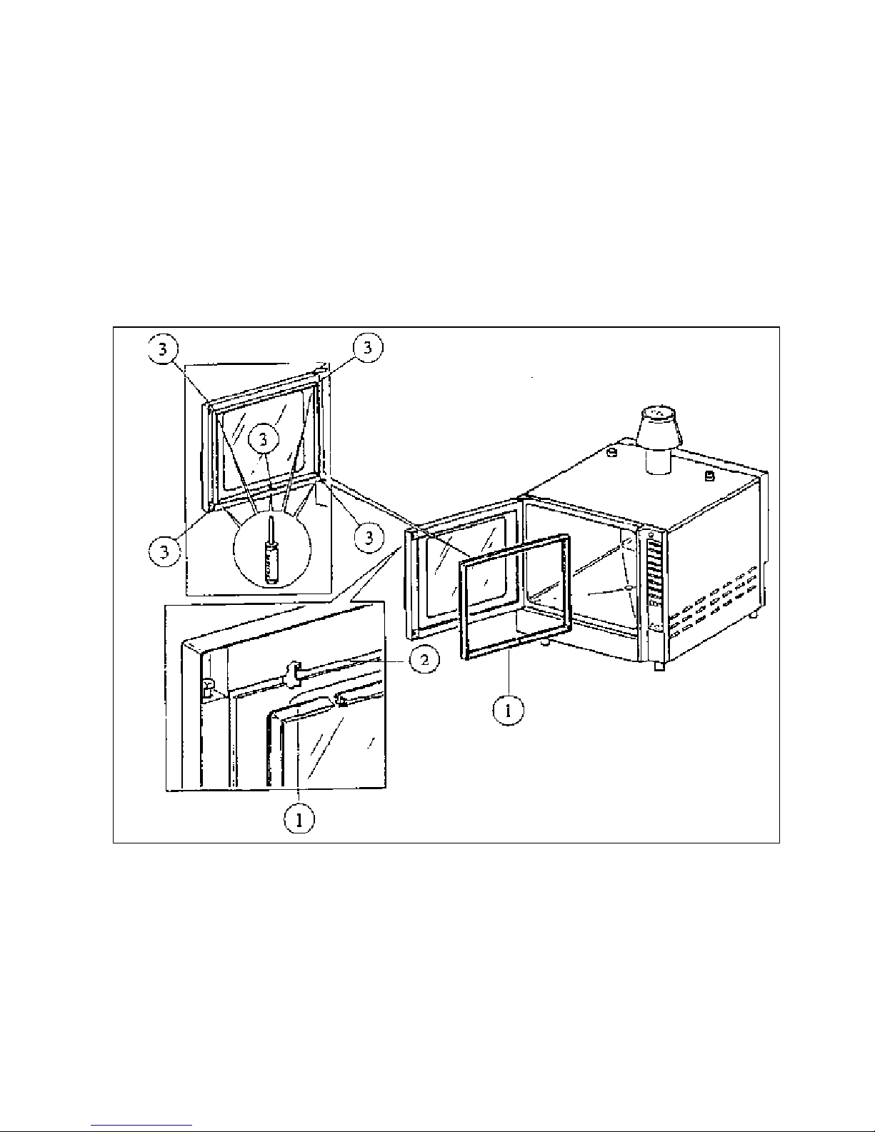
D) Oven door gasket Tab. 8
- Take the gasket out of its seat.
- Clean the seat of the gasket of all
trace of dirt.
- Place the new gasket in its seat (2),
seal the 4 corners with a silicone-based
mastic.
E) Cleaning solenoid valve filters
- Remove the rear panel.
- Remove the water supply pipe.
- Take out the filter and wash it thoroughly.
- Fit it all back together.
TAB. 8
7.2.2 YEARLY MAINTENANCE
This is only to be done by an authorized, skilled technician!
1) Check the seal of the door gasket.
2) Check the seal of the gaskets of the door double-glazing.
3) Check the seal of the lamp-holder glass gasket.
4) Removing and thoroughly cleaning the fan. Open the screen by pushing on the pins and turning them through 90°C.
Remove the fan and clean it thoroughly (left-hand nut).
Fit the screen back on, putting the pins back in their original positions and pushing them
fully in so you hear them click home.
5) It is also recommended to oil the seal of the driving pin passage.
6) Descale the probes, taking care not to swap the wires over.
Page 21

- 21 -
7.2.3 SAFETY DEVICES
CONTROL AND SAFETY SYSTEMS OF THE OVEN
- PROTECTION OF THE AUXILIARY ELECTRIC CIRCUIT.
Controlled by a fuse (6.3 A) on the auxiliary circuit line.
- MOTOR-DRIVEN FAN PROTECTION
The motor-driven fan has an internal overload switch that automatically trips if the windings overheat. Reset is automatic
when normal temperature returns. The likely causes of this safety device tripping comprise: rubbing or stiffening of the motor
fan-pin system, excessive uneven scale on the blade, etc.
- OVEN DOOR MICROSWITCH.
The oven switches off automatically when the oven door is opened.
- SAFETY THERMOSTAT.
This device trips if there is any trouble with the oven temperature control thermostat so the admitted limits are not exceeded.
In the event of a failure, in order to restore operation, take off the control panel on the right and press the red push-button of
the safety thermostat. Notify a technical service centre.
STEAM GENERATOR SAFETY THERMOSTAT
This trips if the temperature in the boiler exceeds a certain level due to a shortage of water and when the two water level
sensors no longer react. One cause may be scale on the water level sensors.
In the event of a failure, in order to restore operation, take off the panel on the right and press the red push-button of the safety
thermostat. Notify a technical service centre.
SYSTEMS CONTROLLING THE LEVEL OF WATER IN THE BOILER
This check is made by the electronic card that controls two sensors: the maximum and minimum sensors. The advantage here
is of disconnecting the power supply to the boiler heating element until the water reaches the necessary level, avoiding
possible failure due to the boiler overheating because of a lack of water.
7.3 SWITCHING OFF IN THE EVENT OF EQUIPMENT FAULTS
IMPORTANT: YOU MUST SWITCH THE OVEN OFF WITH THE MULTI-POLAR SWITCH UPSTREAM.
CLOSE THE WATER SHUT-OFF VALVE.
REQUEST AN AUTHORIZED TECHNICIAN FROM YOUR DEALER.
A) Replacing the light bulb illuminating the cooking chamber (see above paragraph).
B) Waste water/cooking vapour outlet clogged.
If the waste water or cooking vapour outlet gets clogged, you need to:
- Check that the outlet is clear as far as the open siphon.
- Rinse thoroughly with running water and check it flows off freely when drained.
C) The motor-driven fan stops.
There may be two causes:
- The microswitch is defective, or set wrongly, or the door is not properly shut.
- The overload switch has tripped, cutting off the power supply in the event of overheating.
Resetting is automatic.
If the motor stops often, request a skilled technician to find the causes of the trouble.
D) Oven heating fails to work.
- Check whether the door is shut and the fan turns.
- If the heating fails to work, the safety thermostat of the cooking chamber has probably tripped.
In the event of overheating >350°C in the oven, the safety thermostat in the cooking chamber cuts off the
power supply.
- The safety thermostat in the cooking chamber can only be reset by a technician authorized by the dealer.
7.3.1 STEPS TO TAKE IF THE OVEN IS NOT TO BE USED FOR A LENGTHY PERIOD.
After thoroughly cleaning the oven both inside and outside:
- Open the multi-polar switch contacts to cut off the power supply.
- Shut the water valve upstream from the oven.
- Give all the steel surfaces a good wipe over with a cloth lightly soaked in Vaseline oil in order to apply a
protective film.
- Leave the oven door half open.
- Talcum powder on the gaskets.
 Loading...