

Page 1

FSM 10
1RU MONO MIXER
USERS MANUAL
Page 2

THE FSM 10
Introduction
The FSM10 is a 10 channel mono mixer in a 1RU package, designed to accept 9 inputs on
XLR’s at Mic or Line level and the 10th on phono sockets at line level.
Phantom power is selectable for each of the 9 XLR inputs and there are gain trims and internal
jumpers to set input gain for Mic or Line level.
Other features include two band (BASS and TREBLE) EQ on the output, record output and clip
indicators for input and output.
Inputs
The 9 inputs on XLR are balanced (can be strapped unbalanced) inputs, internal jumpers (two
per channel) set the gain range for Mic or Line input and a recessed gain trim accessible
through the rear panel allows the gain to be set as required.
Each of the 9 XLR inputs can have Phantom power by operating a recessed switch just below
the corresponding volume control on the front panel.
The 10th input is stereo on phono sockets at line level and is summed to Mono, there is a
recessed gain trim accessible through the rear panel allows the gain to be set as required.
Each input has a volume control on the front panel.
Outputs
The 10 inputs are mixed and fed through a two band EQ to the output stage which is a Mono
balanced output on a XLR connector (can be strapped unbalanced).
A record output is available on the front panel through a three pole jack socket, the record
output appears when the “REC” button is pushed and has the same content as the main output.
There is the option to remove the 10th input from the mix when the “REC” button is pushed by
moving an internal jumper.
The two band EQ controls and the output volume control are on the front panel.
Clip indication
There are two clip indicator LED’s on the front panel, one indicates if there is one or more of the
inputs clipping and the other indicates if the output is clipping.
Voltage setting
An internal voltage selector sets 230Vac or 115Vac operation.
Factory Setting
The factory setting is channel 1 – 9 set for microphone input, no phantom power and channel 10
is included in the output mix.
Page 3

INSTALLATION
This unit must be earthed.
Decide what configuration you require for the FSM 10, if it is different to the factory setting
follow the instructions below, otherwise go to the set up section.
To change the internal settings first ensure mains power is disconnected, then remove 3 screws
from each side of the top cover and 2 screws from the top of the top cover (8 screws total, retain
for refitting).
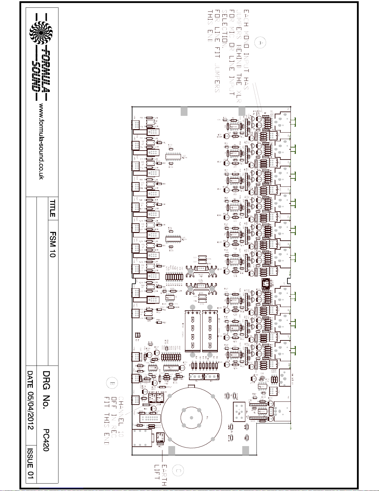
The setting of the options is described below with references to drawing PC420 later in the
manual for the positions of the relevant jumpers.
Internal options (See drawing PC420 later in manual)
Each XLR input has a pair of jumpers to select microphone or line level input, set the inputs as
required.
The 10th input has a jumper which removes this input from the main mix when “REC” is
pressed. This feature is mainly for older style cassette recorders that may at times be used for
the music input.
There is a jumper for ground lift, generally the ground lift should only be removed by a qualified
audio engineer as part of a diagnostic process.
If in doubt contact Formula Sound.
Set up
Connect sources to the required input channels and connect the output as required (usually to
an amplifier).
Set all front panel input volume controls fully anticlockwise (treble and bass leave set to middle),
the output volume control should be set fully clockwise.
Set channel 1 volume control ¾ clockwise, if required select phantom power with the recessed
switch adjacent to volume control (press with a small screwdriver).
Apply a signal and adjust the recessed gain control on the rear panel adjacent to the input
(using a very small flat blade screwdriver) for the required output level. If the clip LED is
illuminated the input level is much too high.
Return the volume control to fully anticlockwise and repeat for all channels.
www.formula-sound.co.uk
Formula Sound Limited
Unit 23; Stadium Business Centre
North End Road
Wembley
HA9 0AT
Tel: +44 (0) 208 900 0947 Fax: +44 (0) 208 903 8657 email: [email protected]
Page 4
Page 5

TECHNICAL SPECIFICATION
INPUTS 1 – 9 XLR connectors
Set to MIC
Noise ref 150R EIN –123dB
Gain max +65dB
Input impedance >2K Ohms active balanced
Set to Line
Noise @max gain EIN -100dB 20Hz-20KHz
Gain max +30dB
Input impedance >10K Ohms active balanced
INPUT 10 Gold plated phono connectors
Max I/P level +20dBV
Input impedance 10K Ohms
OUTPUT (EQ set flat)
Distortion THD @ 1 KHz OP +10dBV <0.01%
Output impedance (Balanced) <100R
Max O/P (Into 600R) +25dBV
20Hz – 20KHz +/- 0.5dB
RECORD OUTPUT Stereo jack socket
OUTPUT LEVEL 0dB nominal
Output impedance >1K ohm
EQ RANGE
TREBLE +/-10dB
BASS +/-10dB
Power
220-240V AC standard (115V to order. Or consult user manual to change)
Mains fuse 220-240v operation 250mA slow blow
Mains fuse 110-115v operation 500mA slow blow
I.E.C. Mains connector
Finish
Front and Rear panel Black anodised aluminium with silver notation
Case black plastic coated steel
Dimensions
19" rack mounting. 1RU
Width 482mm (19") Depth 200mm (7.9") Height 44mm (1.75")
Formula Sound reserve the right to alter the specification without notice.
Page 6

FORMULA SOUND LIMITED
UNIT 23; STADIUM BUSINESS CENTRE; NORTH END ROAD; WEMBLEY; MIDDLESEX; HA9 0AT
TELEPHONE +44 (0)208-900-0947 FAX +44 (0)208-903-8657
www.formula-sound.co.uk email [email protected]
E.U. CERTIFICATE OF CONFORMITY
We declare that the products listed conform to the following directives and standards
89/336/EEC amended by 92/31/EEC and 93/68/EEC
BS EN 50082-1 BS EN 50081-1
PRODUCT TYPE
FSM 10
The CE mark was first applied in 1995
Signed
B. J. Penaligon General Manager
Attention
The attention of the specifier, purchaser, installer, or user is drawn to the fact that good
wiring practice must be observed when connecting the above equipment. Good quality
connectors and screened cables must be used for all audio connections. Twin screened
cables should be used for all balanced lines.
THIS EQUIPMENT MUST BE EARTHED
CONSULT THE USERS MANUAL FOR TECHNICAL DETAILS
 Loading...