

Page 1
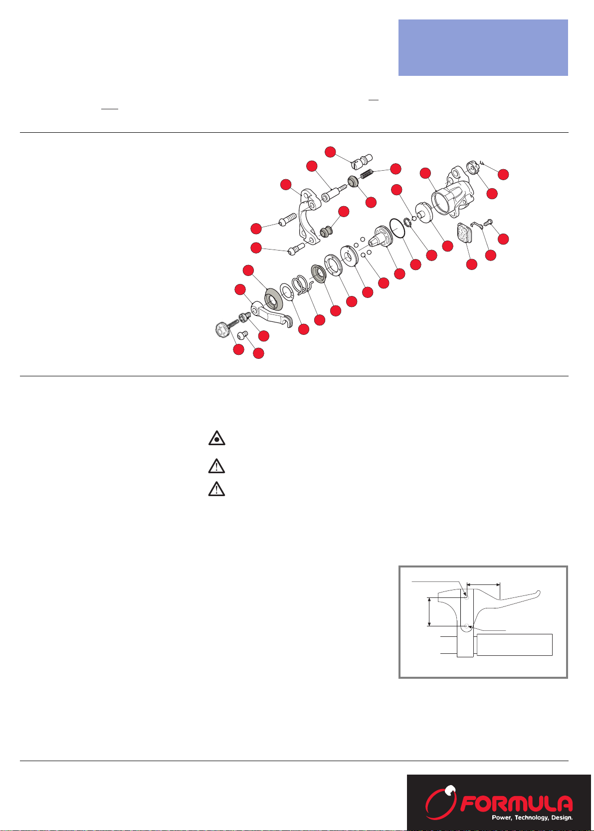
Technical Information
1
2
3
4
5
6
7
8
9
10
11
12
13
14
15
16
17
18
19
20
21
22
23
24
25
26
27
28
8A
29
Fulcro
Attacco cavo
Leva tipo per pinza ACTIVA
Min 35mm
35-38mm
Sheet
MD-1 and Activa braking systems have certain differences between them; the pads, the discs and the system of adjustment of the internal pad. A rapid method of knowing which is which is the colour of the levers: the MD-1 levers are red
whilst the Activa levers are black.
It is important to underline that the pads of the Activa braking system are compatible with the MD-1 pincers as long as the
Activa disc is utilised. The methods of intervention are pointed out in this manual.
LIST OF TOOLS:
- TORX T25 spanner (disc screws);
- 5mm hexagonal spanner (pincer
attachment screw);
- 8mm open spanner (wire-grip
screw);
- 3mm hexagonal spanner (wiregrip screw/Md-1 lever screw);
- 4mm hexagonal spanner (Activa
lever screw);
- 2.5mm hexagonal spanner (MD-1
external pad adjustment grub
screw/Activa internal pad screw)
- Small-bladed screwdriver (Activa
external pads);
- Fine-point pincers (pad fixing
tongue);
- 17mm open spanner (pincer fixing screw);
- Pincer fixing spanner code FD
40010-60 (MD-1/Activa);
Activa
MD1
INTRODUCTION
Our disc brakes with hydraulic controls have been
designed to obtain the maximum in braking performance
level, reliability, safety and lightness of components. To
maintain these characteristics it is necessary that the correct sized brakes are installed on the bicycle bearing in
mind the greater pressure that these brakes transmit.
Badly installed or badly maintained brakes can diminish
the braking efficiency and can cause dangerous situations
for the safety of the cyclist. This manual has been produced to instruct the personnel who are specialised in the
assembly, reassembly and maintenance procedures of
these brakes and also as information for the user about
the general notes and the safety norms to follow in case
of interventions by the user.
GENERAL NOTES:
- It must be noted that any maintenance or repair inter-
vention carried out during the guarantee period that do
not respect the suggested advice of this instruction
manual will cancel the guarantee forthwith. The use of
non-original spare parts will also cancel the guarantee
- Utilise only the special tools; do not substitute with any
other equipment because it could irreparably ruin the
component. All tools must be in good condition.
- Utilise cleaning and lubricating products that are prefer-
ably biodegradable and do not dispose of the used fluid
in the environment.
- Always operate in a clean place and equipped with ade-
quate work clothing as prescribed by the safety norms.
- Always keep a first aid kit available.
GENERAL NORMS
This technical information sheet is intended as a guide for
the correct and safe use and assembly of the braking system and for its reasonable maintenance.
Constantly observing the norms indicated in this manual
guarantee the best performance, use and long life of the
braking system and avoids the more common causes of
accidents that could occur during use or maintenance.
The following symbols are utilised in every paragraph in
this manual:
WARNING: The inobservance of the advice
quoted could cause damage to the equipment.
ATTENTION: The inobservance of the advice
quoted could cause damage to either equipment or the user.
ATTENTION: Carefully read the SAFETY
NORMS so as to guarantee the correct use of
the braking system.
GENERAL SAFETY NORMS
· To carry out correctly all the procedures of
removal, reassembly and overhaul it is necessary
to have an adequate technical specialisation, a
perfect knowledge of the braking system and to
have completely read this technical information
sheet.
· Do not place the hands near or into moving parts.
Utilise five-finger robust gloves that do not
reduce the sensitivity and the strength of grip.
· Instruct the user to not alter the parameters of
the braking system to obtain a performance different to the performance foreseen by the design
and testing department of Formula.
· Before starting assembly operations examine the
work area for possible dangerous conditions. Do
not work in the dark – use as much lighting as
possible and check that they are efficient.
· Concentrate on making sure that all precautions
have been taken before starting any work so that
the use of the components will not cause damage.
SAFETY NORMS OF THE BRAKING SYSTEM
· The disc brake must be assembled on wheels that
are adapted for this type of use. A wheel with
insufficient section radius or with radial engagement of the spokes can collapse under the braking action exercised by the braking system and
can cause serious damage or accidents.
· Frequently check the tension and the condition of
the spokes. A damaged spoke could break and
interfere with the braking system thereby causing serious damage or accidents.
· The frame and the fork of the bicycle must be
predisposed to the assembly of the braking system. It is only in this way that the correct dimensions of the supports and the correct positioning
of the components can be guaranteed.
· THE BRAKING SYSTEM NEEDS A CERTAIN PERIOD OF SETTLING DOWN TO OBTAIN MAXIMUM
EFFICIENCY.
Cable attachment
35-38 mm
Type of lever for the ACTIVA pincer
· THE BRAKING SYSTEM HAS BEEN DESIGNED
AND MUST BE UTILISED ONLY WITH HANDLEBAR LEVERS THAT ARE OF THE V-BRAKE TYPE
Min 35mm
Fulcrum
- 1 -
Page 2
- 2 -
A
B
C
1
INSTALLATION
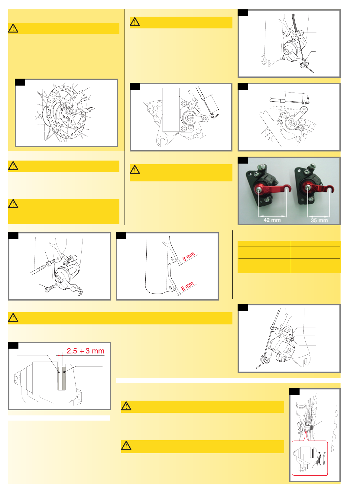
1: Brake disc assembly
Place the disc brake A onto the hub B of an already assembled
wheel taking care to respect the direction of rotation
expressed by the arrow C on the flange of the disc. Fix the disc
with the appropriate M5 screws and tighten in a cross-wise
direction to 5.75N·m (50.61 lbs. per sq. inch) ± 5%.
Thoroughly clean the disc with ethyl alcohol to remove any
traces of grease or oil.
N.B. The disc can have four or six fixing holes.
D
E
2a 2b
2a, 2b: Front/rear pincer assembly
Assemble the front and/or rear pincer onto the relative attachments as shown in the figure. Fix them by using the M6 screws
D-E to a torque pressure of 9N·m (79.22 lbs. per sq. inch) ±
5%. Apply a weak thread-locking liquid.
ATTENTION: Consult the safety norms
X
3c
X
3b
3d
3b, 3c, 3d:
Position the terminal of the sheath on the sheath stop F.
Insert the cable into the grip G at X distance as shown in
the figure. Tighten the screw of the grip to a torque pressure of 2.91N·m (25.62 lbs. per sq. inch) ± 5%.
Note: Leave approximately 2 cms of cable after the
cable grip F and bend it to 90° immediately after
the cable grip F.
ATTENTION: Cables and sheathes that are
too short could limit the ride-ability of the
bicycle and could cause serious accidents.
Consult the table below for the “X” distances:
X
MD1 / Activa
with a 42mm lever 50
MD1
with a 35mm lever 42.5
ATTENTION: Consult the safety norms
ATTENTION: If the thickness of the relative
attachment on the fork or frame is less or more
than 8mm it will be necessary to substitute the fixing
screws with screws of the correct length.
G
F
3a
3a: Cable assembly
Insert the complete cable onto the V-BRAKE type brake
lever as indicated by the manufacturer of the lever.
The cable and the sheath must be the correct
length, bearing in mind the movement of the various elements of the cable that must not interfere
with any moving parts of the bicycle.
ATTENTION: Consult the safety norms
I
H
L
4a
4a: Wheel assembly
Before assembling the wheel with the disc mounted, it is necessary to check that on the fixing screws I after the pommel H
there is the security circlip L.
ATTENTION: Consult the safety norms
4b
External pad
Internal pad
4b: Also check that the distance between the pads is always 2.5-
3mm as shown in the figure. If the measurement is less, exert a
light pressure on the external pad until the pad comes to its resting position. Assemble the front and/or the rear wheel as indicated by the manufacturer.
M
M
5
INSTRUCTIONS FOR USE
5: Preliminary adjustments and braking adjustments
Before utilising the braking system it is necessary to effectuate the preliminary adjustments
as follows.
Bring the internal pad in contact with the disc. Screwing in the pommel M, the pad comes
nearer to the disc; unscrewing it makes it move away.
ATTENTION: Consult the safety norms
ATTENTION: Also in the case of the inserted pad, check that the pommel M
is always screwed in even lightly to avoid losing it.
Page 3
10a
- 3 -
N
6
Q
O
P
7
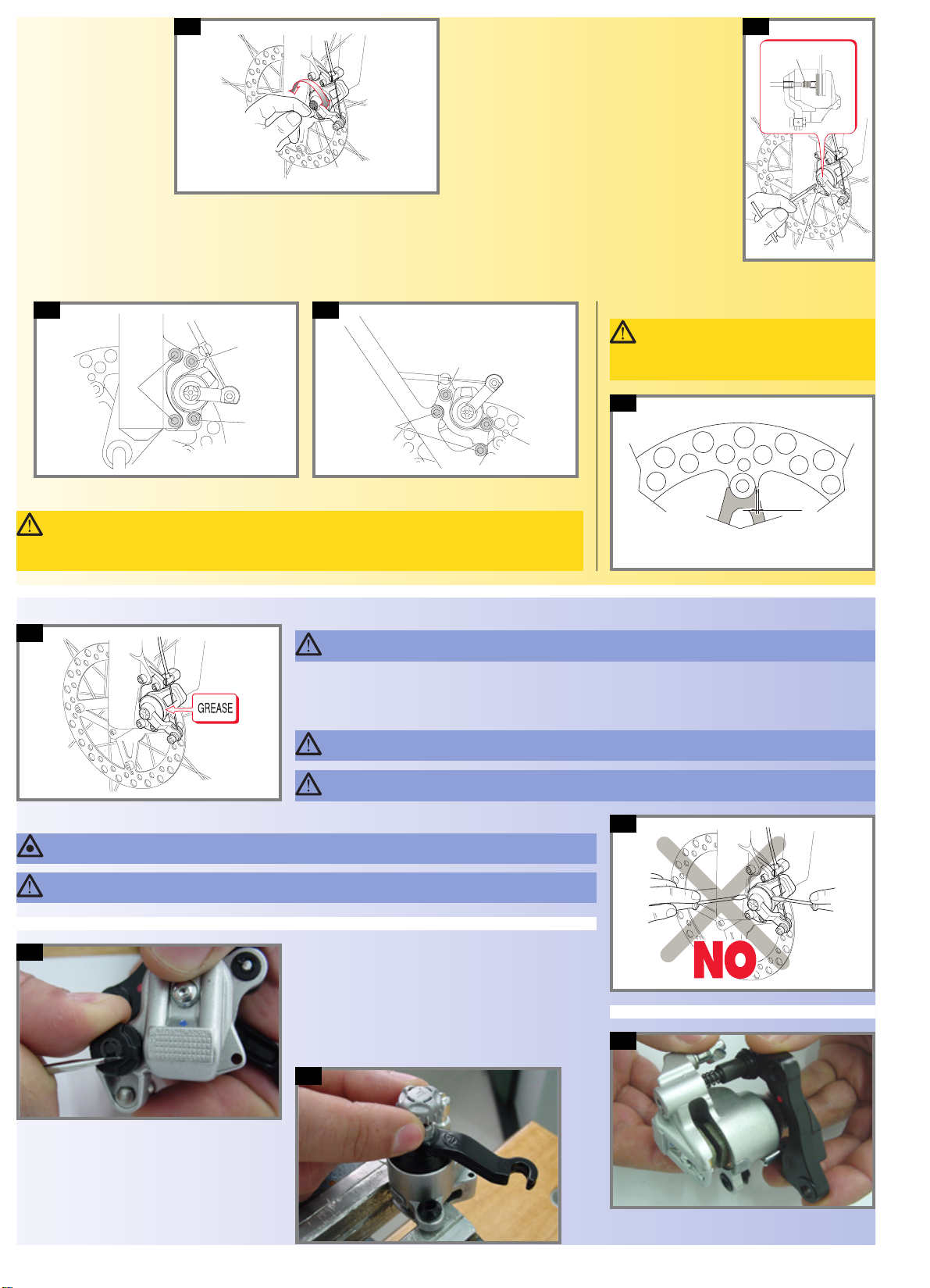
6: Activa version
Adjust pommel N to bring the
external pad to the desired
distance from the brake disc
to obtain the correct action.
Rotating the pommel N in a
clockwise direction, the pad
comes nearer to the disc.
Rotating in an anti-clockwise
direction, the pad can be distanced from the disc by simply
applying a light pressure with
the finger.
7: MD-1 version
Utilising a 3mm hexagonal spanner, unscrew the fixing
screw O of the pincer lever P. Utilising a 2.5mm hexagonal
spanner, screw the fixed internal grub screw Q in a clockwise direction until the external pad just makes contact with
disc. Replace the fixing screw O.
Test the braking system and check if the movement of the
lever at the handlebar functions correctly and performs the
desired braking action.
If the movement of the lever is too long, act upon the screw
adjuster of the handlebar lever.
Repeat the adjustment operation above described from time
to time until the pads are completely worn out and then
substitute the pads of the braking system (See chapter 16).
If the action of the lever is too long, repeat the adjustment operations so that the desired situation is obtained.
Repeat the adjustment operations above described until the pads are completely worn out
and then proceed with the substitution of the brake pads (See chapter 12).
R
S
R
8a
S
R
R
8b
8a, 8b:
ATTENTION: The braking system needs a certain period of settling down to obtain maximum efficien-
cy. Before making the final approval of the set-up it is necessary to effectuate at least one hundred
braking actions and then proceed with a further adjustment to the set-up and a check on the tightness of the
screws. R (MD-1/Activa) and S (only Activa).
1 mm
9
Only for the MD-1 version (riveted disc)
9:
ATTENTION: After a running-in period there
is a small amount of play between the external disc and the disc support.
This play must not exceed 1mm.
MAINTENANCE
10a:
According to the type of use and the atmospheric conditions, it is necessary to clean the pincer periodically using an adequate
biodegradable degreasing material that will not damage the pincer.
Accurately clean the moving parts of the braking system.
ATTENTION: Consult the safety norms
ATTENTION: Protect the disc and the pads with a cloth to avoid contact with lubricating material. This
could cause an alteration to the abrasive gripping action between the pads and the disc.
ATTENTION: Utilise only ethyl alcohol to clean the disc. Utilising different products from that described
above could represent a serious danger for the user.
10b
10b:
WARNING: Never disassemble the pincer lever utilising tools.
ATTENTION: Never touch the brake disc after utilising the braking system because this could cause injury.
11a
PINCER REMOVAL
N.B.: The numbers in parentheses indicate the reference to
the parts shown in the exploded view.
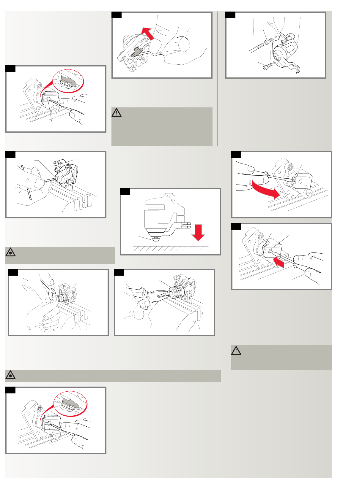
11a: Utilising a screwdriver, remove the circlip (29).
11b
11c
11b: Completely unscrew the pommel (22) underneath the
circlip and remove the adaptor (3).
11c: Insert the pincer in a vice and unscrew the pommel
(23) until it is completely removed.
Page 4
- 4 -
11f
11l
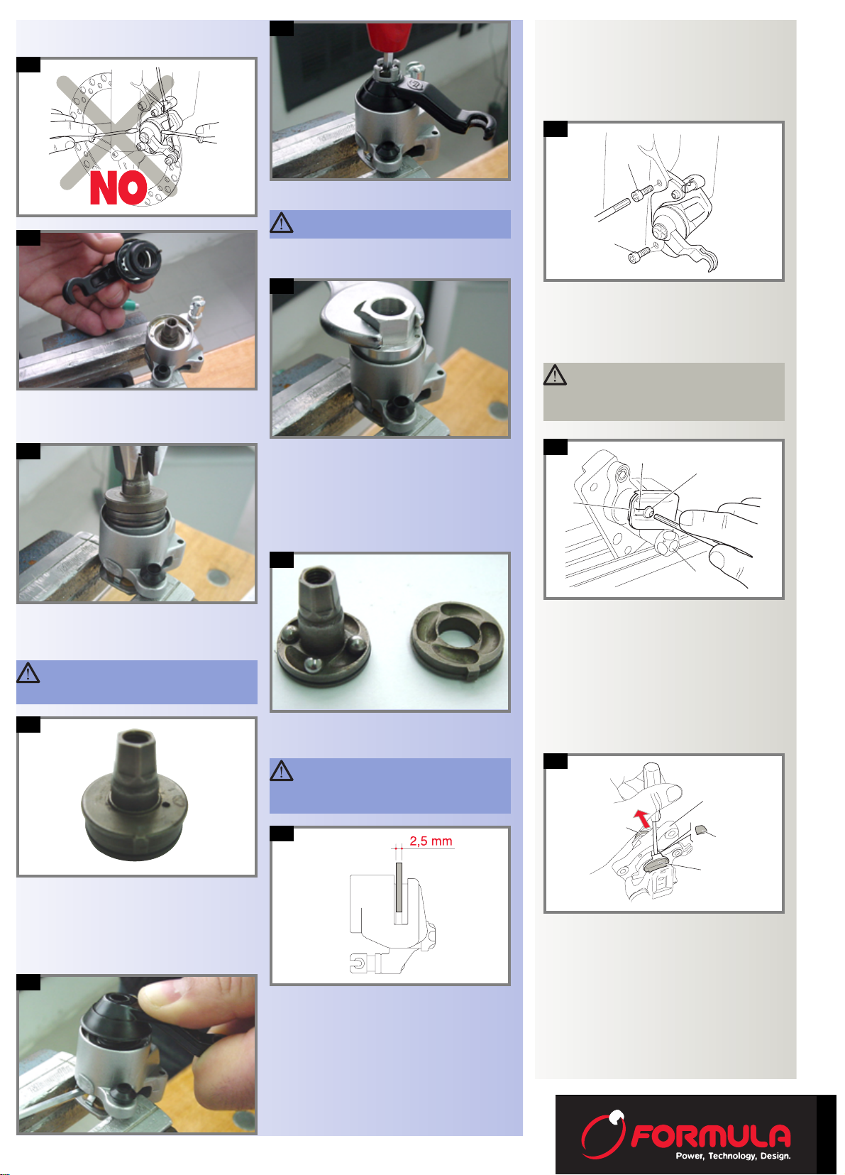
11f: Remove the lever unit.
11l: Before reassembling the rotor unit, smear a small
quantity of grease in the seats of the ball bearings.
11g
11m
11g: Utilising the tool shown in the figure, unscrew the
internal ring (12) in an anti-clockwise direction and
remove it.
11n
Remove the internal pad (19) from the pincer body and
clean it using a brush dipped in alcohol.
To clean the rotor unit it is necessary to remove the external pad (18).
11n: After having substituted the rubber (11), reassem-
ble the lever unit taking care to insert the lever pin into
the hole of the counter-rotor.
Rotate the lever and position it as shown in the figure
keeping it pushed downwards.
Grease the pins of the adaptor (3) and reassemble the
remaining components proceeding in the reverse order
of removal.
11d
11d: Using a 4mm spanner, unscrew the screw (8) as
shown in the figure.
11e
11h
11h: Utilising pincers, slide out the rotor unit
11i
11i: Separate the rotor (15) from the counter-rotor (13)
and clean the components using a brush dipped in alcohol.
Reinsert the internal pad (19) and fix it with the metal
tongue (20) and the appropriate screw (21).
11m: Insert a 2.5mm spacer between the two pads.
Reinsert the rotor unit and fix it with the internal ring (12)
utilising the appropriate tool.
11e:
ATTENTION: Never disassemble the pincer
lever using tools.
ATTENTION: Be careful to not drop and lose
the internal ball bearings (14) of the rotor
unit.
ATTENTION: Be careful to reassemble the
rotor unit so that the teeth of the counterrotor coincide with an angle of the hexagon of the
rotor.
T
T
12
SUBSTITUTION OF THE BRAKE PADS
N.B.: The numbers in parentheses indicate the reference
of the parts in the exploded view.
12: Activa version
Remove the cable from the lever of the braking system
without unscrewing the cable grip.
Remove the pincer unit by slackening the fixing screws T.
13: Removal of the internal pad
Unscrew the screw U (21) utilising a 2.5mm hexagonal
spanner.
Straighten the safety tongue V (20) and remove the used
pads Z.
ATTENTION: Be careful when using the
screwdriver: the dimensions of the parts are
small and therefore this operation could cause
injuries to the hand. Wear protective gloves.
13
14: External pad removal
Bring the pommel Y (22) into the position where it is
touching the circlip.
Extract the plastic protection K.
Insert a small-bladed screwdriver (see figure) between
the pincer body J (24) and the support surface of the pad
W.
Apply a light pressure in the direction indicated by the
arrow and remove the worn out external pad.
Rotate the external pad adjustment pommel X (23) in an
anti-clockwise direction until it stops.
J
K
W
X
14
V
U
Z
Y
Page 5
15a, 15b: Assembly
AB
C
C
L
F
G
O
P
M
N
E
D
E
H
I
Insert the external pad first, positioning it with the nib part
downwards. Utilising a small-bladed screwdriver, press as
shown in the figure.
Reassemble the protection K into its seat.
Insert the internal pad fixing it with the security tongue A
(20) that must be bent with a pair of pincers and with the
fixing screw B (21). Apply a medium Loctite thread-locking liquid to the screw.
15b
15a
16
17 a
17b: Take the pincer unit in hand and holding it firmly by the
extremity of the lever, hit the part of the fixing screw E (8A)
sharply onto a rigid surface.
Then completely unscrew the screw and remove the lever.
WARNING: During removal, hold the lever tightly so that the spring does not bounce out of its
seat.
Reassemble the pincer unit onto the fork or the frame
respecting the instructions in the braking system manual.
Furthermore, effectuate the adjustments mentioned in
chapter 5.
ATTENTION: The braking system needs a
certain period of settling down to obtain
maximum efficiency. Before making the final
approval of the set-up it is necessary to effectuate
at least one hundred braking actions and then proceed with a further adjustment to the set-up and a
check on the tightness of the screws.
17a: External pad removal
Place the pincer D in a vice utilising protective pieces to not
damage the pincer.
Slacken the screw E (8A) of the lever turning it three times in
an anti-clockwise direction.
17 b
16: MD-1 version
Remove the cable from the brake lever without unscrewing the
cable grip.
Remove the pincer unit by slackening the fixing screws C.
18a
18b
17 c
17c: Unscrew the ring G (18) utilising the appropriate tool (available from the manufacturer).
17d: Utilising pincers, slide out the pad-carrying piston unit H. It is necessary to effectuate this operation with particular
care so that the ball bearings (14) do not fall out of their seat.
Slowly slide out the pad carrier I from the piston unit H being careful to not drop the ball bearings.
Substitute the worn pad carrier with a new one.
WARNING: Position the new pad as shown in chapter 21a, 21b.
19
17 d
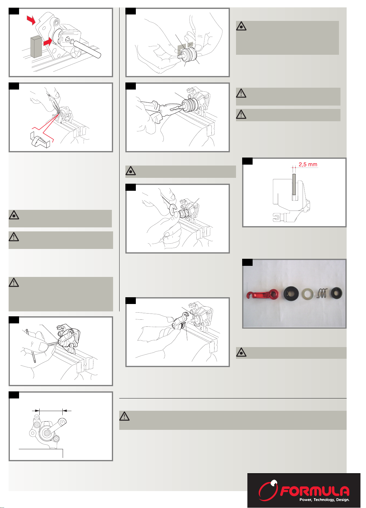
19: Sintered internal pad assembly
Insert the internal pad and fix it with the security tongue O (20) and with the fixing screw P (21). Apply medium Loctite threadlocking liquid to the screw.
N.B. Use new parts that are included in the kit.
18a, 18b: Internal pad removal
Maintain the pincer unit mounted on a vice with protective pieces as shown in the figure, without tightening too
much so that the pincer unit is not damaged.
Lift up the tongue L (20) utilising a small-bladed screwdriver and slide out the tongue utilising the appropriate
pair of pincers.
17b: Effectuate a pressure on the pad support pin until
the circlip N comes out.
ATTENTION: Be careful when using the
screwdriver: the dimensions of the parts are
small and therefore this operation could cause
injuries to the hand. Wear protective gloves.
Slide out the worn out pad M and substitute it with a new
one.
CONTIN UED ON PAGE 6
- 5 -
Page 6
- 6 -
21 c
21c:
T
21 d
21d: Reassemble the ring T (18) utilising the appropriate
tool and tighten to a torque pressure of 11N·m (96.83 lbs.
per sq. inch) ± 5%.
Z
21 g
21 e
21e: Lever unit assembly procedure
When assembling the lever unit, be careful that the long pin
of the spring is inserted into the lever.
Furthermore, place the spring in one of the two holes present
on the gasket and on the lever to adjust the tension of the
spring.
50 mm
36,5 mm
21 h
21g, 21h: Tighten the fixing screw Z (8A) of the lever to a
torque pressure of 4.5N·m (39.61 lbs. per sq. inch) ± 5%.
Check that the lever rotates easily and smoothly.
For long lever
For short lever
Reassemble the pincer unit onto the fork or the frame of the bicycle respecting the instructions previously mentioned.
N.B.: See the disassembly of the pincer for the cleaning/lubrication of the moving parts (see chapter 21a)
V
U
21 f
21f: Reassemble the lever unit with the spring onto the pin-
cer unit.
Insert the lever unit into the pin of the piston unit, positioning it onto the hexagonal conical coupling in such a way that
the lever is found in the position as indicated in the figure.
20a
20b
20a, 20b: Organic internal pad assembly
Assemble the new pad by inserting it into the seat of the
piston unit (as indicated by the arrow in the figure) in
such a way that the pad support pin inserts into the
appropriate hole.
Insert an adequate spacer between the pincer and the
pad, then insert the new circlip and fix the pad by pressing on the pad with a tool that has an 8mm external diameter and a hole of 3.5mm.
Bend the tongue onto the support and with the appropriate flat, curved pincers tighten the part of the tongue with
the pad as indicated in the figure in such a way that there
is no play.
ATTENTION: If this warning is not respected
there could be the risk of accident with dan-
ger to life
ATTENTION: Effectuate the bending of the
tongue with great caution so as not damage
the tongue. Be careful when effectuating this operation: the dimensions of the parts are small and
therefore this operation could cause injuries to the
hand. Wear protective gloves.
WARNING: Never reuse the old tongue or
circlip: there are new ones included in the
kit with the new pads.
Q
R
S
21 a
Q
21 b
21a, 21b: Organic/sintered external pad assembly
Before inserting the piston complete with the pads onto
the brake unit it is necessary to lightly lubricate (use
ALVANIA EP (LF) 2) normal grease for the ball race movement) the internal part of the unit and the external circumference of the piston unit.
Reassemble the piston unit and the pad carrier to the pincer unit, inserting the tooth Q in the appropriate seat of
the cylinder on the pincer unit.
ATTENTION: Do not put too much grease
because the excess quantity could infiltrate
to the braking parts.
ATTENTION: Do not dirty the pad with
grease. This could be dangerous to life.
WARNING: If the support R slides out from
the ball bearing carrier during the substitution of the pad carrier S it will be necessary to
reposition it in such a way that the tooth Q on the
ball bearing carrier is aligned with the angle of
the hexagon of the piston as shown in the figure.
WARNING: Insert a 2.5mm spacer between the
two pads as indicated in the figure.
WARNING: Ensure that the pin V of the spring is
inserted into the hole U of the piston unit.
ATTENTION: The braking system needs a certain period of settling down to obtain maximum efficiency.
Before making the final approval of the set-up it is necessary to effectuate at least one hundred braking
actions and then proceed with a further adjustment to the set-up and a check on the tightness of the screws.
 Loading...