

Formsprag Long Life Holdbacks Series, LLH 700, LLH 1027 Service & Installation Instructions
P-222-14-FC
Bulletin 2224
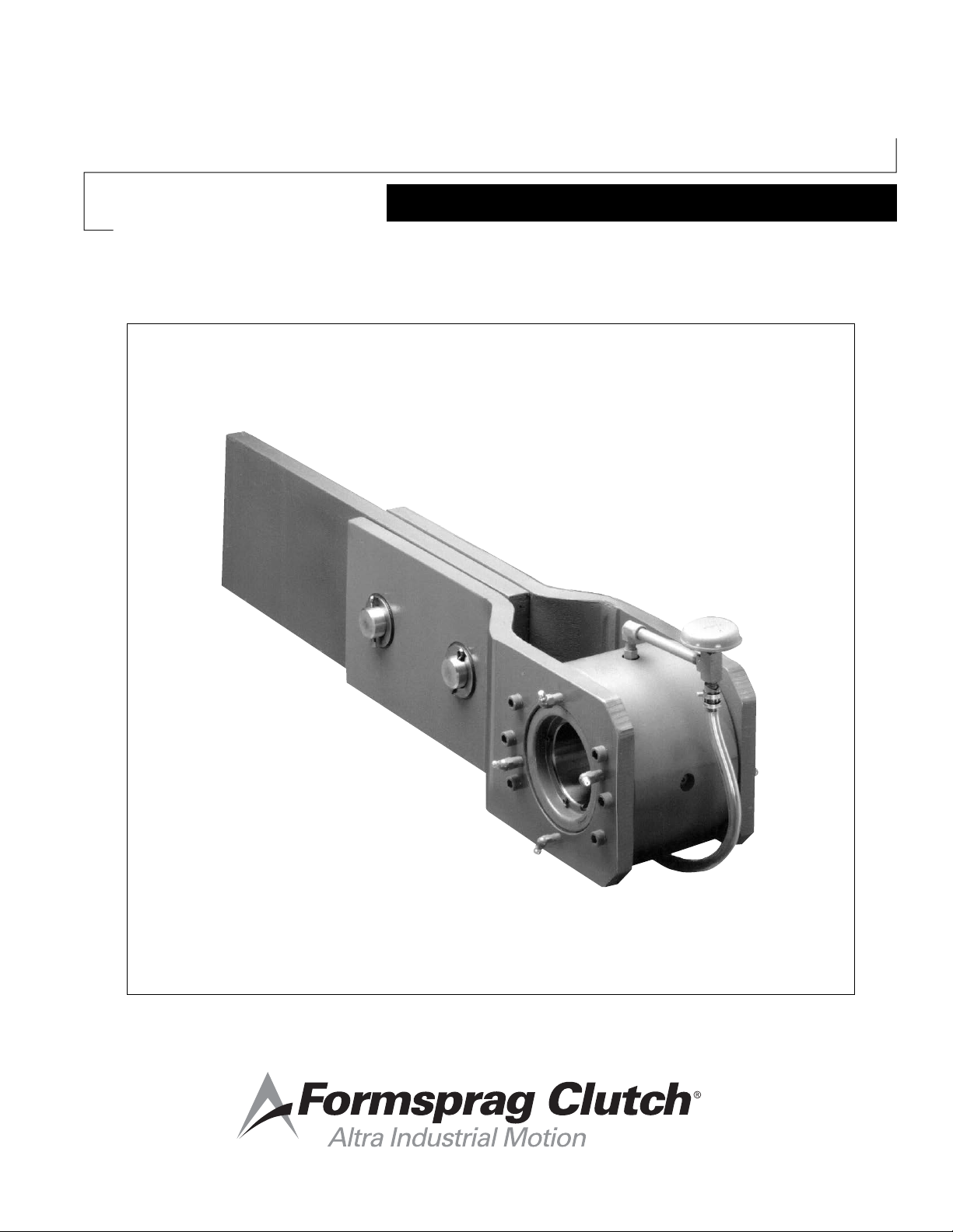
Long Life Holdbacks
Model LLH™ 700 thru 1027
Service & Installation Instructions

Introduction
Formsprag LLH – Long Life Hold-backs are specifically
designed and built for head shaft mounting on
conveyors to prevent reverse rotation. They contain full
complements of load carrying Formchrome®‚ sprags, in
“Free-Action” Retainers, for maximum torque capacity.
Follow the step by step installation and maintenance
instructions in this bulletin for optimum performance and
life.
Prior to installation in a location outside the
primary drive line, shaft run-out should be
measured in at least two locations in the
Holdback mounting area. Measured values should
not exceed those in the following table:
Max Overrunning
Speed, RPM
Thru 100 0.010
Thru 150 0.006
Thru 250 0.004
Thru 400 0.002
Maximum TIR,
inches
Failure to follow these
instructions may result in product damage,
equipment damage, and serious or fatal injury
to personnel.
Pre-installation Check
1. Before installing, check Shaft to Bore fit:
Holdback Bore Recommended Fit*
inches inches
1.937 to 2.125 .001 to .0035 loose
2.250 to 2.500 .001 to .0040 loose
2.625 to 3.000 .001 to .0045 loose
3.250 to 4.000 .001 to .0055 loose
4.250 to 5.937 .001 to .007 loose
6.000 to 6.937 .002 to .008 loose
7.000 .002 to .005 loose
*If a press fit is necessary under special
circumstances. Do not exceed .001 inches tight.
In some cases, builders of equipment in which a
Holdback is used specify other shaft fit limits. In
this event, direct questions concerning fit limits to
the equipment builder.
Shaft Run-out Recommendations for LLH
Holdback Units
LLH Holdback units are designed for installation
on primary drive line shafting with typical
dimensional tolerances and run-outs. Some
applications dictate installation in locations not
in the primary drive line, i.e. in locations where
tolerances and run-outs exceed “typical” values.
In these situations, some basic measurements
are required to determine the suitability of the
proposed mounting location. Holdback lubrication
sealing and overall product life can be adversely
affected by excessive shaft run-out or lack of
straightness.
Across the Holdback mounting area, the shaft
should be straight within 0.003 inches per foot of
length.
These requirements are based on maintaining
acceptable axial and radial vibration levels on
the Holdback. Installations that exceed these
limits can result in leakage of lubricant from the
Holdback, excessive seal wear, and premature
failure of bearings and/or Sprags.
Set Collars (not furnished)
Figure 1
2. Key and Keyseat
A hardened key, (25-40 Rockwell “C” scale) is
furnished with the Holdback and is as long as
the inner race keyseat for proper support. Check
shaft keyseat. Key must fit with a “push” fit. Do
not use a driving or force fit.
3. Rotation
Turn the inner race to check the Holdback for
direction of rotation. The arrow on the clutch
name plate indicates the direction of inner race
overrunning.
2 Formsprag Clutch • 800-927-3262 P-222-14-FC • 5/19

Angular Clearance
Grease In
Shaft Rotation
Important: Angular and axial clearances must be
maintained at all times. Set collars (or other
retention devices) should be used on the shaft to
maintain axial clearance.
0.5
(12.7)
B
Axial Clearance
1.0
(25.4)
END VIEW
1.0
(25.4)
6. Position Holdback and torque arm. Coat torque
arm pins and pin holes with anti-seize compound
(furnished). Insert pins and cotter keys as shown
in (Figure 1).
7. Attach torque arm stops to conveyor frame or
supporting structure. The stops are required to
prevent rotation of torque arm when holdback
torque is applied. Allow clearance between
stops and torque arm as shown in Figure
2. The clearance is necessary to permit free
axial and angular movement of the torque arm
resulting from shaft runout and eccentricity.
We recommend set collars on shaft to prevent
Holdback from shifting which would eliminate
this clearance.
Figure 2
The torque arm reaction force is the force which the
torque arm stops must resist. Formsprag recommends
that the stops be at least 3/4 of the distance (B) away
from the center line of the clutch.
Installing
1. Place inboard set collar on shaft. Set collars
should be used to keep Holdback in position on
shaft. Otherwise, the Holdback might shift on
shaft causing torque arm to bind.
2. Coat Holdback bore, shaft and key with an
anti-seize compound to facilitate installation
and removal. A supply of this compound is
furnished with each new clutch assembly.
3. Place Holdback and key on shaft. Be sure that
shaft is free of nicks and burrs.
Note: Oil lubricated Holdbacks should be
mounted on horizontal shafts only. For
mounting on vertical shafts, contact
Formsprag.
4. Apply pressure to end face of inner race only.
Pressing against the outer race could preload the
bearings excessively. To simplify mounting, should
a bore-to-shaft fit of .001 inches tight be required
(this is tightest allowable) immerse Holdback in
hot, clean oil (not to exceed 200°F/93°C) for ten
to fifteen minutes before mounting.
5. Secure Holdback in position on shaft. Use flat
washer fastened to shaft end with screw, snap
rings or set collars to keep Holdback in position
on shaft. It is essential to hold unit in position on
the shaft.
Note: Torque arms may be installed at any angle,
however, vertical torque arms should be
installed at lease 10° from the true vertical
position. The Holdback should be mounted
in an orientation so that the weight of the
torque arm will keep the torque arm in
constant contact with the reacting surface
and structure.
8. Grease auxiliary seals. These labyrinths are built
into each Holdback to minimize the harmful
effects to the oil seals from dusty or abrasive
atmosphere. For instructions on regreasing these
seals, follow instructions in (Figure 3).
Purge
Grease
Out
Figure 3
9. Install oil sight gauge attachment. Follow
instructions in (Figure 4).
Install breather in highest position after Holdback
installation is complete. Follow instructions in
(Figure 4).
Formsprag Clutch • 800-927-3262 P-222-14-FC • 5/19 3

3/4 Full Min
7/8 Full Max
Center Line
Horizontal
Oil sight gauge must be installed so that “3/4
(19.05) full” level (shaft horizontal center line) is
clearly visable in the plastic tubing. Two sets of
opposing lubrication holes, at 90 intervals, are
provided in the outer race for the sight gauge.
Select highest and lowest opposed holes to install
gauge.
unless other lubricant was specified on order.
The use of lubricants in clutch
assemblies, other than those shown, can result in
improper sprag engagement. Improper sprag
engagement may cause personal injury or property
damage.
Oil sight gauge must be installed so that “3/4 full” level
(shaft horizontal centerline) is clearly visible in the plastic
tubing. Two sets of lubrication holes, at 90˚ intervals, are
provided in the outer race for the sight gauge. Select
highest and lowest opposed holes to install gauge.
Formsprag is not responsible for any changes
made by the manufacturers in their lubricants.
Figure 4
10. Check Holdback lubrication and replace any oil
lost while installing gauge.
Note: Oil lubricated Holdbacks which will not
be operated within three months after
installation should be filled completely
full of oil to prevent corrosion of interior
surfaces. Excess oil should be drained
prior to operation.
Auxiliary Seal Lubrication
1. Lubricate auxiliary seals every Three Months of
normal operation, more often if extremely dusty
conditions prevail. The auxiliary grease seals are
protective barriers for the oil seals. Lubricants with
EP additives must not be used. Use any of the
following greases, or equivalent:
Lubriplate Low Temp (Fiske Bros.)
Mobil SHC-32 (Mobil Oil)
Rykon #2 (Amoco)
Amolith #2 (Amoco)
2. With a low pressure grease gun, pump seals full,
through fittings on both sides, until old grease
is purged and fresh grease runs out around the
entire circumference of the seal.
The use of any lubricants, other than those
listed in this bulletin, will automatically void any
warranty.
Do not use lubricants containing
slippery additives, or those having extreme
pressure characteristics such as any EP type
lubricants.
Oil Lubrication Maintenance
1. Lubrication is the most important Holdback
maintenance factor. Keep oil clean.
2. Check oil level weekly. To add oil, remove
breather cover and pour oil into Holdback through
the breather housing.
3. Flush Holdback every Six Months with mineral
spirits.
Important: If Holdback operates under severe
dust conditions or twenty-four
hours per day, FLUSH EVERY
THREE MONTHS.
4. Flush with mineral spirits and relubricate before
operating if the Holdback has been in storage or
out of service for six months or more.
3. Holdbacks supplied for grease lubrication may
use Fiske Brothers Lubriplate Low-Temp grease
for all lubrication. See Grease Lubrication.
Oil Lubrication
Use oil selected from the table below according to
the temperature existing at the Holdback. Holdback
should be 3/4 full of oil. Holdbacks are shipped from
Formsprag 3/4 full of Mobil DTE Heavy Medium oil
4 Formsprag Clutch • 800-927-3262 P-222-14-FC • 5/19

Temperature Range Recommended Lubricant
+20°F to 150°F Mobil DTE Heavy Medium
(-7°C to 65°C) Shell Turbo Oil 68
(Max. permissible High grade Automatic Trans.
ambient temp.) Fluid (ATF)
Texaco Regal R&O 68
Chevron GST Oil 68
Exxon Terristic Oil 68
AMOCO Industrial Oil 68
Sunoco Sunvis Oil 931
Gulf Harmony
-10°F to +150°F Mobil Gargoyle Arctic C
(-23°C to +65°C) Heavy
High grade Automatic Trans.
Fluid (ATF)
Texaco Regal R&O 46
Chevron GST Oil 46
Sunoco Sunvis Oil 921
-40°F to +150°F Mobil Jet Oil 2
(-40°C to +65°C) Shell Turbo Oil 500
Exxon Turbo Oil 2389
Standard Esso Turbo Oil 2389
MIL-L-23699 or MIL-L-7808
Military Specification Oils
Ambient temperature below -40°F/-40°C consult Formsprag.
Storage
Formsprag LLH Holdbacks are shipped 3/4 full of oil
and ready for operation. If the Holdback is to be stored
for a long period of time (6 months to 2 years), it must
be completely filled with oil (Mobil Gargoyle Arctic C
Heavy) and stored under a roof at above freezing
temperatures. At the customer’s request, Formsprag
will prepare the Holdback for storage in accordance with
our Spec SP-194.
Flushing Procedure
1. Remove pipe plug from lower “Tee” in oil sight
gauge and drain oil.
Grease Lubrication – (No sight Gauge)
1. Grease lubricated Holdbacks, available by
special order, are packed at the factory with
Fiske Brothers Refining Company Lubriplate
Low-Temp grease. Use no other grease unless
specific recommendation has been obtained
from Formsprag to use an alternate.
Grease lubricated Holdbacks
must operate in ambient temperatures of
+20°F/-7°C or higher.
2. Do not attempt to substitute grease lubrication
in a standard oil lubricated Holdback. The use of
grease lubrication in Holdbacks intended for oil
lubrication may cause a malfunction. To convert
from oil to grease lubrication, a change of internal
construction may be required which can only be
accomplished by Formsprag Clutch. Consult the
Formsprag Clutch Service Department and give
clutch model number.
Grease Lubrication Maintenance
1. Lubricate Holdback every three months. If
Holdback operates under sever dust conditions
or twenty-four hours per day, grease monthly.
2. Use Fiske Brothers Refining Company Lubriplate
Low-temp Grease only. (Do not use alternate
greases without specific recommendation from
Formsprag Clutch.)
3. Clean grease fittings by wiping with clean cloth.
4. Pump grease in with grease gun until fresh
grease flows freely from around the entire seal
circumference on both sides of the Holdback.
Seals have been installed to provide automatic
venting and to allow purging of old grease and dirt
during regreasing. This will lubricate both clutch
mechanism and auxiliary seals.
2. Reinstall drain plug.
3. Fill Holdback completely with mineral spirits or
Kerosene.
4. Operate conveyor for one or two minutes to
cause Holdback to overrun. This will circulate
Sight Gauge Service (Ref. Figure 5)
• Sight gauge tubing (8) should be mounted on a
vertical plane.
• Breather (10) must be above tube (8) and elbow
(3) fitting.
solvent for better cleaning of internal parts.
• Apply a suitable pipe joint compound, such as
5. Remove drain plug and drain solvent.
6. Reinstall drain plug. Add oil to 3/4 full level as
shown on the oil sight gauge.
Permatex #2 or equivalent, to the threads making
sure sealant does not get into lube.
Replacement Oil Sight Gauges may be ordered from
Formsprag. Simply provide Holdback model Number.
Formsprag Clutch • 800-927-3262 P-222-14-FC • 5/19 5

(10)
(1)
(2)
(3)
(4)
(5)
(6)
(7)
(8)
(9)
Gasket
Adapter
Elbow
Nipple
Tee
Nipple
Clamp
Tubing
Drain Plug
Breather
10
4
Clutch Rebuilding Service
Disassembly and Repair of Formsprag Clutches in
the field is not Recommended.
3
Formsprag clutches are precision devises manufactured
2
1
5
under careful controls to meet exacting standards.
When reconditioning is required, clutches should be
6
7
returned to Formsprag directly, through the Distributor,
or through the Original Equipment Manufacturer.
Formsprag clutch and holdback are mechanical devices
8
designed to protect mechanical equipment from rotation
in the opposite direction and should generally not be
considered Safety Devices. Formsprag clutches and
1
2
5
9
7
6
holdbacks have surfaces which wear with use over time
and as a result will need to be replaced. The clutches
and holdbacks do not offer a feature for determining the
time of their replacement. As a result the decision for the
time of replacement must be made by the operator of
the equipment based upon the specific application and
performance of the clutch or holdback.
Figure 5
Oil Sight Gauge Assembly
CL-7362-5
Replacement Filter Elements
Keep adequate supply of filter elements on hand. They
can be purchased from Great Lakes Filter Media Co.,
5151 Lorraine, Detroit, Michigan 48208
To Clean Breather Filter Element
1. Loosen wing nut, lift off whole breather.
2. Remove cover and filter. Rinse filter in solvent.
3. Reinstall breather housing. Add clean oil to the
mark on housing.
4. Reinstall cover and filter. Tighten wing nut.
Breathers
Clutch Model Breather No.
Mfr. No. Formsprag No.
LLH-700 569022-01 CL-30703
Dry Filter
LLH-750 to
LLH-1027 FAOB-07 CL-30703-5
Oil Bath Filter
Packaging
Your Formsprag clutch, carefully wrapped in Vapor
Inhibitor type activated paper for corrosive protection
and packed in a shipping box conforming to the
requirements of Rule 41, Uniform Freight Classification,
may be stored for up to two (2) years and reshipped
without added packaging.
These instructions cannot cover all details or variations
in equipment and applications nor provide for every
possible contingency which may be met in installation,
operation or maintenance. Should further information be
needed, contact Formsprag Clutch.
For additional technical and dimensional information on
LLH Series clutches refer to Formsprag Overrunning
Clutch Catalog P-956 or call Formsprag Application
Assistance at 1-800-927-3262.
Rotating Equipment
Rotating equipment is potentially dangerous and should
be properly guarded. The user should check for all
applicable safety codes (in local area) and provide a
suitable guard.
6 Formsprag Clutch • 800-927-3262 P-222-14-FC • 5/19

NOTES
Formsprag Clutch • 800-927-3262 P-222-14-FC • 5/19 7

Warranty
Formsprag LLC warrants that it will repair or replace (whichever in its sole discretion it deems advisable) any
product it manufactured and sold which proves to be defective in material or workmanship within a period of one
(1) year from date of original purchase for consumer, commercial or industrial use. This warranty extends only to
the original purchaser and is not transferable or assignable without Formsprag LLC’s prior consent.
This warranty covers normal use and does not cover damage or defect which results from alterations, accident,
neglect, disassembly, or improper installation, operation, or maintenance.
Formsprag LLC’s obligation under this warranty is limited to the repair or replacement of the defective product. In
no event shall Formsprag LLC be liable for consequential, indirect or incidental damages of any kind incurred by
reason of manufacture, sale or use of any defective product. Formsprag LLC neither assumes nor authorizes any
other person to give any other warranty or to assume any other obligation or liability on its behalf.
www.formsprag.com
23601 Hoover Road
Warren, MI 48089
586-758-5000
P-222-14-FC 5/19
 Loading...