

Page 1

1
MIMO WiTDM® Series
KW50-O8500
User’s Manual
2017/11/02 v2
Page 2

2
Copyright
There is no any clear or implicit assurance in the user's manual of our company, including the
assurance of selling or installing for the special purpose. There are rival's volumes to carry on the
power to alter or revise in our company, if alter and forgive me for not issuing a separate notice. You
can’t duplicate any content of this manual by the written permission of our company.
About this manual
The purpose to use this manual is for install the wireless Bridge. This manual is including
disposing course and method and helping the customer to solve the unpredictable problem.
The following typographical conventions are used in this purpose:
Notice:
This indicates an important Note.
Caution:
This indicates a warning or caution
Bold Type:Indicates the function, important words, and so on.
Page 3

3
Index
CHAPTER 1 INTRODUCTION ............................................................................................................................................ 4
INTRODUCTION ....................................................................................................................................................................... 4
APPEARANCE OF PRODUCT ..................................................................................................................................................... 4
FEATURES AND BENEFITS ....................................................................................................................................................... 4
CHAPTER 2 HARDWARE INSTALLATION ..................................................................................................................... 5
SYSTEM REQUIREMENT .......................................................................................................................................................... 5
PRODUCE KIT ......................................................................................................................................................................... 5
HARDWARE INSTALLATION ..................................................................................................................................................... 5
LED DESCRIPTIONS ............................................................................................................................................................... 5
CHAPTER 3 SYSTEM SETUP .............................................................................................................................................. 6
FACTORY DEFAULT SETTINGS ................................................................................................................................................. 6
USING THE WEB MANAGEMENT ............................................................................................................................................. 7
STATUS ................................................................................................................................................................................... 8
MAP .................................................................................................................................................................................... 10
SYSTEM ................................................................................................................................................................................ 11
CHAPTER 4 WIRELESS SETTINGS ................................................................................................................................ 15
BASIC WIRELESS SETTINGS .................................................................................................................................................. 15
CHAPTER 5 MANAGEMENT ............................................................................................................................................ 19
CHANGE PASSWORD ............................................................................................................................................................. 19
UPGRADE FIRMWARE ........................................................................................................................................................... 21
BACKUP/RESTORE ................................................................................................................................................................ 22
EVENT LOG .......................................................................................................................................................................... 23
REBOOT ................................................................................................................................................................................ 23
CHAPTER 6 TROUBLESHOOTING ................................................................................................................................. 24
FAQ ..................................................................................................................................................................................... 24
SERVICE SUPPORT ................................................................................................................................................................ 25
Page 4
4
Chapter 1 Introduction
Introduction
Thank you for choosing the Formosa’s KW50-O8500 Wireless Outdoor MIMO WiTDM Bridge. It is a PoE
power supply, waterproof, and dust-proof wireless bridge that is specially designed for connecting among
multiple network location. The KW50-O8500 work on 5GHz, and it based on powerful TDMA technology that
provides higher channel bandwidth for long distance connect.
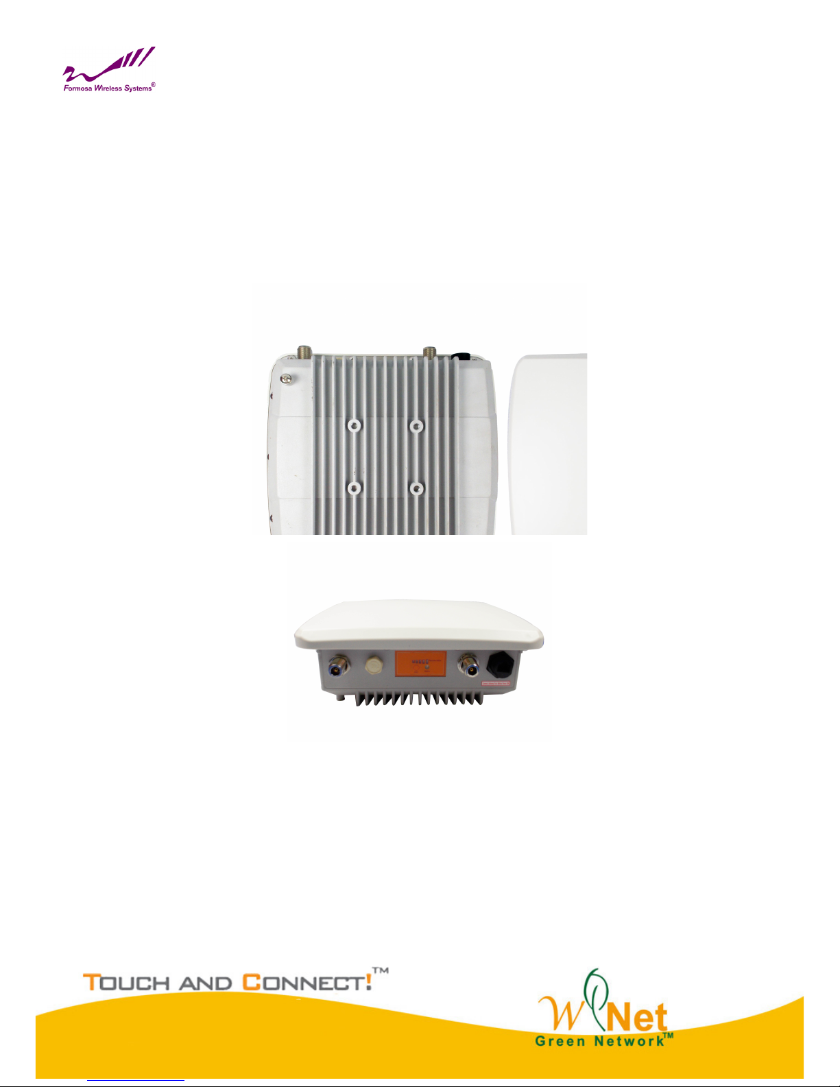
Appearance of Product
KW50-O8500
Features and Benefits
Support Power over Ethernet (PoE)
IP68 class of enclosure
Support TDMA mechanism, to ensure quality for multi-media application
Easy to install and friendly to user, just plug and play.
Provides Web-based configuration utility.
Page 5
5
Chapter 2 Hardware Installation
System Requirement
Installation of MIMO WiTDM® outdoor unit of KW50-O8500 system requirement:
Two PCs with automatic speed control NIC support the transfer rate of 10/100/1000 Mbps data.
The IP address of NIC should be the same subnet with the AP, the default IP address of AP is 192.168.1.1
Microsoft Internet Explorer 6 or above.
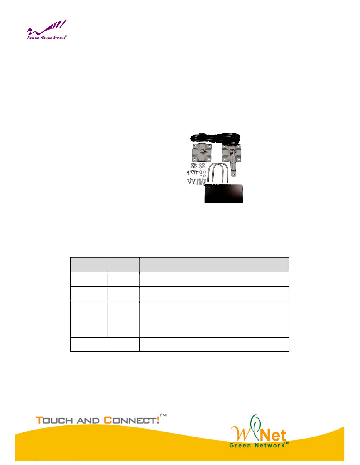
Produce Kit
KW50-O8500 x 1
Injector-GT3 (48V, 0.65A) x 1
Mounting Kit x 1
User’s Manual CD x1
Hardware Installation
The following steps will help you while installing MIMO WiTDM®.
LED Descriptions
LED Status Description
Power Green Power ON
STATUS Green Power on Flash 1 Sec , then OFF
Remote
RSSI
Green
CPE:Go around while surveying ( not connect yet ),
Represent strength of RSSI after connected.
Low ( 1 LED ) → High ( 5 LEDs )
RST Push 5 seconds then release to reset device to default
LED Definition
Page 6
6
Chapter 3 System Setup
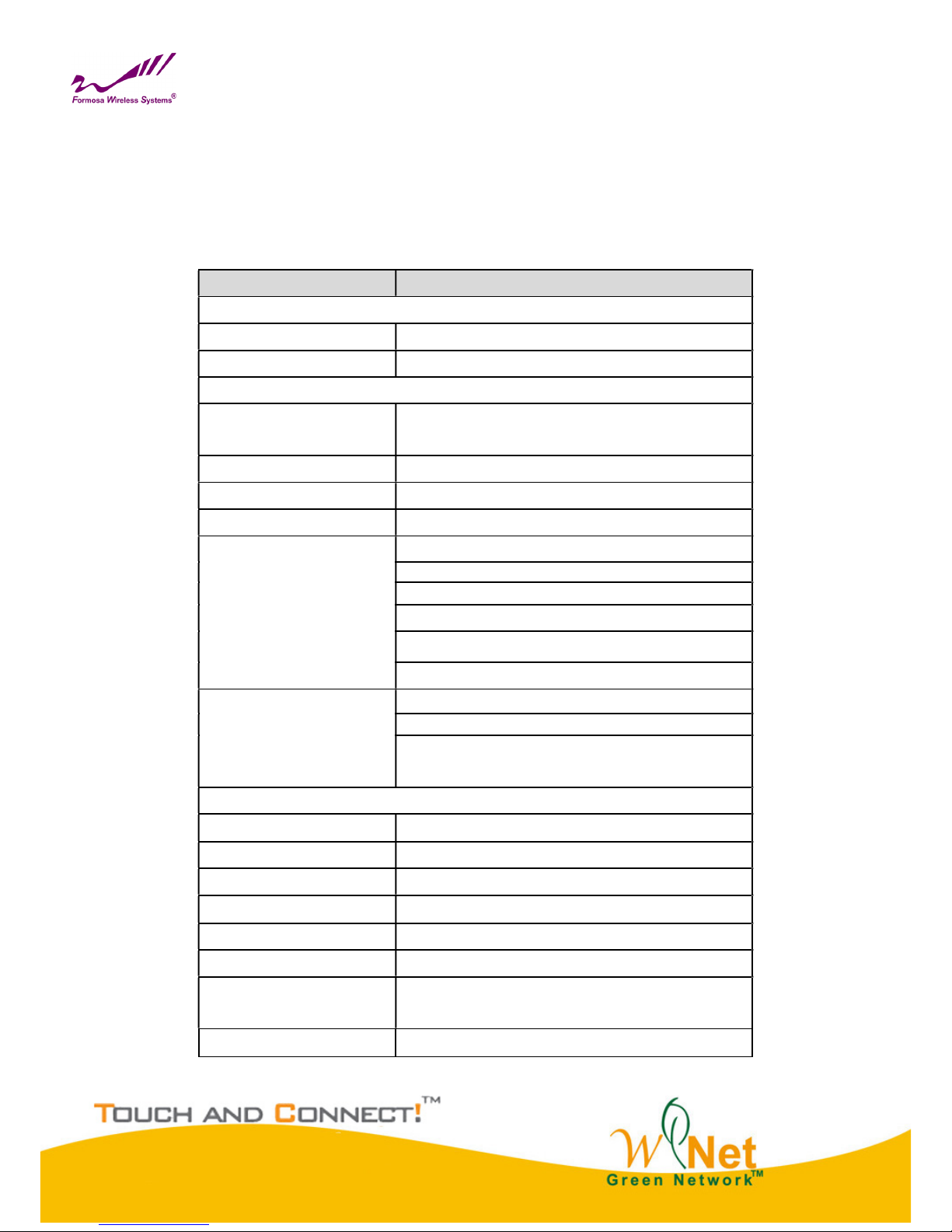
Factory Default Settings
We’ll elaborate the KW50-O8500 factory default settings. You can re-acquire these parameters by default. If
necessary, please refer to the “Restore Factory Default Settings”.
Item Factory Default
Login Information
User Name admin
Password password
Basic Settings
Device Name
DEVICExxxxxx (xxxxxx Represent the last 6
digitals of the MAC address)
Ethernet Data Rate Automatic
Spanning Tree Protocol Enable
VLAN (802.1Q) Disable
IP Settings
IP Type:Manual
IP Address:192.168.1.1
IP Subnet Mask:255.255.255.0
Default Gateway:0.0.0.0
Primary DNS Server:0.0.0.0
Secondary DNS Server: 0.0.0.0
Time Settings
Time Server: None
Time Sever Port: 123
Time Zone: (GMT-08:00)Pacific Time(US &
Canada);Tijuana
Wireless Setup
Radio Frequency (RF) Enable
Operation Mode Base Station
Network ID Wireless
Time Slot
10ms
RF Bandwidth 20MHz
Channel / Frequency 5060 MHz
Data Rate
SS BPSK 1/2 – SS 64QAM 5/6 , SS BPSK 1/2 – DS
64QAM 5/6
Output Power Full
Default Settings
Page 7
7
Using the Web Management
The KW50-O8500 provides you with user-friendly Web-based management tool.
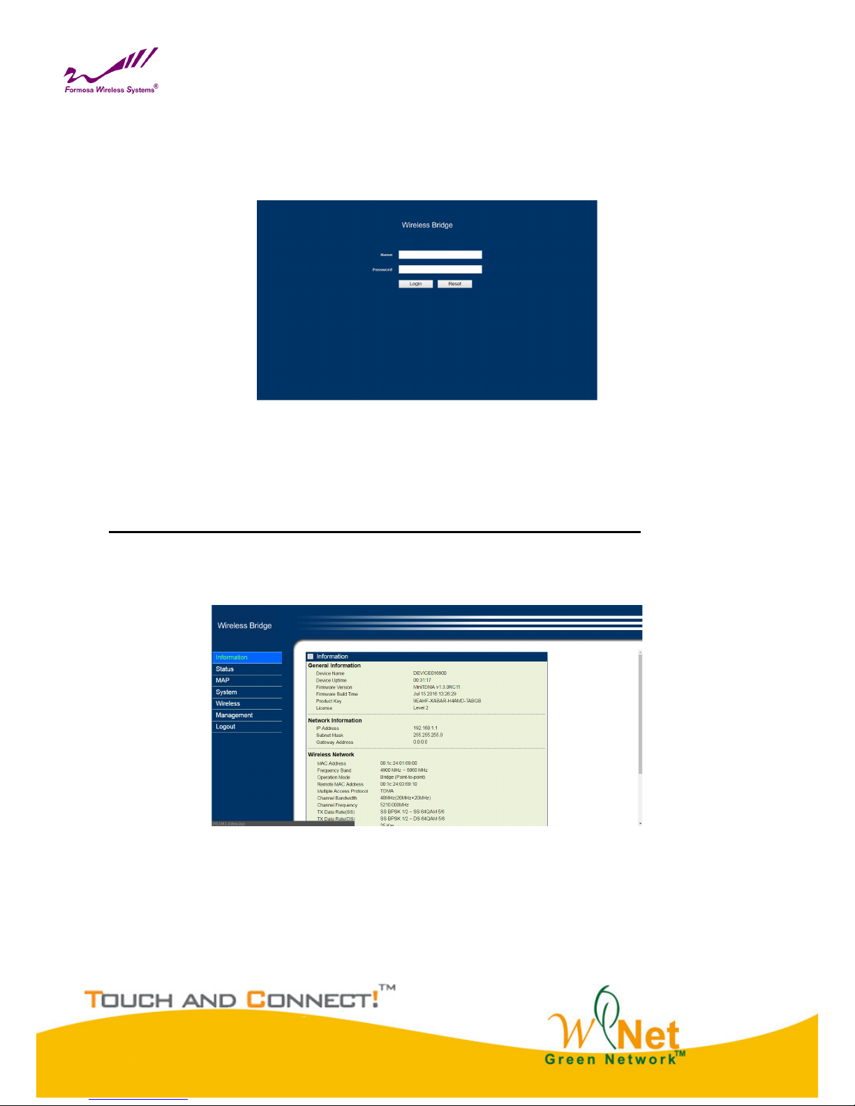
Open IE and enter the default IP address (Default: 192.168.1.1) and Login as below:
Login Interface
Enter the username (Default: admin) and password (Default: password) and click “Login”
Caution:
IP address of your PC must be the same subnet of device
After login, you can check basic information of device, such as MAC address off device, Firmware version, etc.
Device Information
Page 8
8
Status
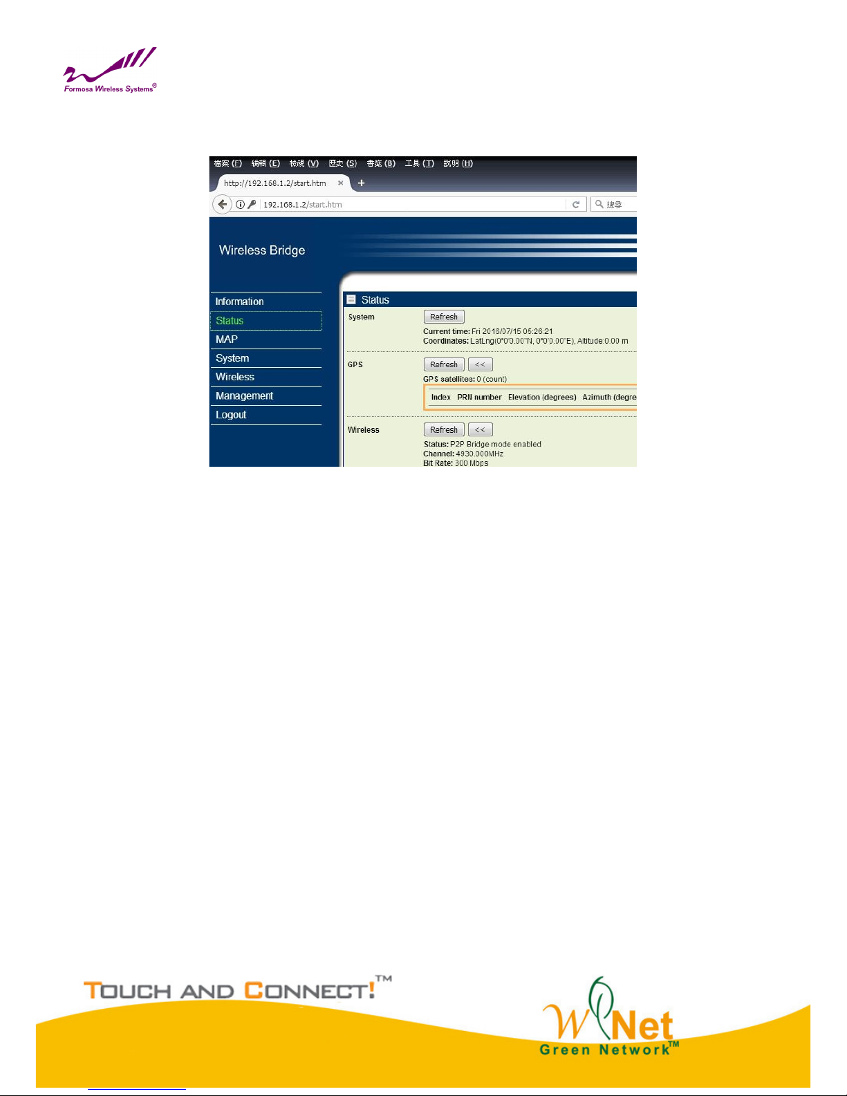
Select Status, you will get the information as below,
Status
System: This field identifies the current time and Coordinates.
GPS: GPS Satellites Information (Only for GPS Model)
Wireless:
MAC Address: MAC of Remote MIMO WiTDM Bridge.
IP Address: IP of Remote MIMO WiTDM Bridge.
Local RSSI: RSSI of Local Bridge.
Remote RSSI: RSSI of Remote Bridge.
Tx/Rx Rate: Current Data Rate of Tx/Rx.
Tx/Rx Modulation: Current Modulation of Tx/Rx.
How to Setup MIMO WiTDM Bridge
Get Position, Longitude and Latitude
Get Direction and Azimuth
Signal Status, In Status page, it can show remote bridge Signal Strength for local bridge (Local RSSI) and local
bridge Signal Strength for remote bridge (Remote RSSI). We can decide the best direction of antenna from
following steps:
1. We check the Local RSSI only in one side. (We call it local side.)
2. Fix remote side antenna, and adjust local side antenna. In local side, check the “Local RSSI” first, to
find a best Local RSSI and then fix the local antenna.
Page 9

9
3. Adjust the Remote antenna, to find the Best Remote RSSI, and then fix the remote antenna.
4. If “Local RSSI” is changed, and worse than before, adjust local antenna again to get a best one and fix
local antenna.
5. If “Remote RSSI” is changed and worse, adjust remote antenna again.
6. Follow the same ways to get a better Local RSSI and Remote RSSI value. And Fix both side antennas.
Port Statistic:
Display Wireless and Ethernet statistics of packets including transmitted and received packets, Unicast, Broadcast,
Multicast and total Packets. Click “Refresh” can get instant information.
Page 10
10
MAP
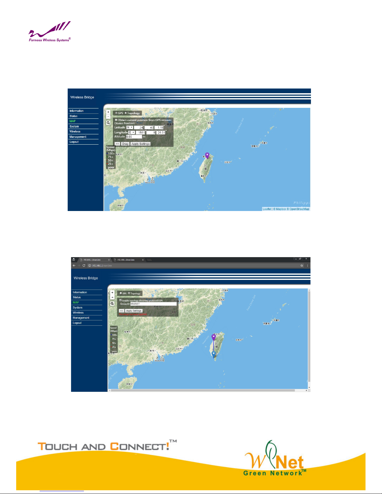
Global Positioning System, GPS (Only for GPS Model)
Select GPS, Can obtain current position from GPS receiver.
Topology
Select Topology, Can enable topology discovery protocol to establish the structure of connections.
Page 11
11
System
Basic Settings
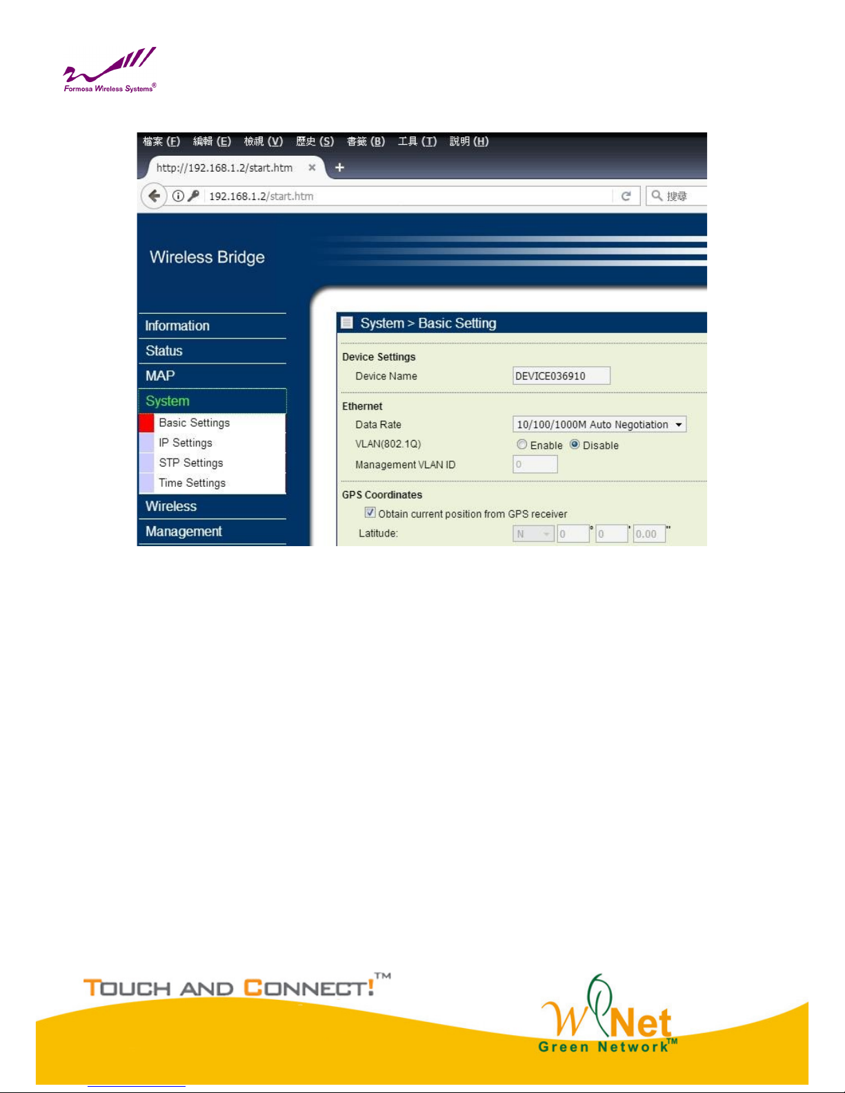
Device Name
Specify the device name, which is composed of no more than 15 characters with (0-9), (A-Z), (a-z) or (-).
Due to support WINS, You can use “Device Name” instead of IP address to access device via WEB interface. For
instance, device named as DEVICE0000FF, you can enter “DEVICE0000FF” in the IE, then click “ENTER” and
WEB page; or use “ping” command to check settings is active or not, such as ping DEVEICE0000FF.
Ethernet Data Rate
Specify the transmission rate of data, default is Automatic.
Automatic 10/100/1000Mbps / T-base10Mbps / T-Base100Mbps
VLAN
Virtual local network can promote network security. By default, the function is disabled.
GPS Coordinates (Only for GPS Model)
Obtain current position from GPS receiver.
Page 12
12
IP Settings
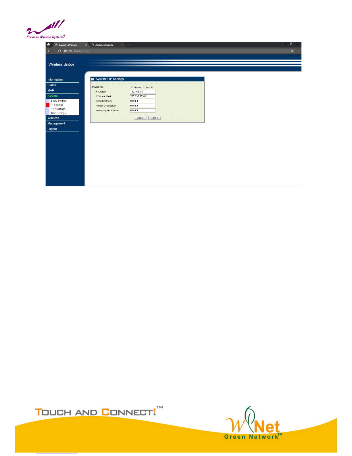
IP Address
This IP in your network must be unique ,default is 192.168.1.1.
IP Subnet Mask
Use subnet mask to ensure two devices in the same network, default is 255.255.255.0
Default Gateway
Default gateway and DNS server for your local area network which connects to LAN port.
Primary DNS Sever
First choice of domain name server
Secondary DNS Sever
Second choice of domain name server
Page 13
13
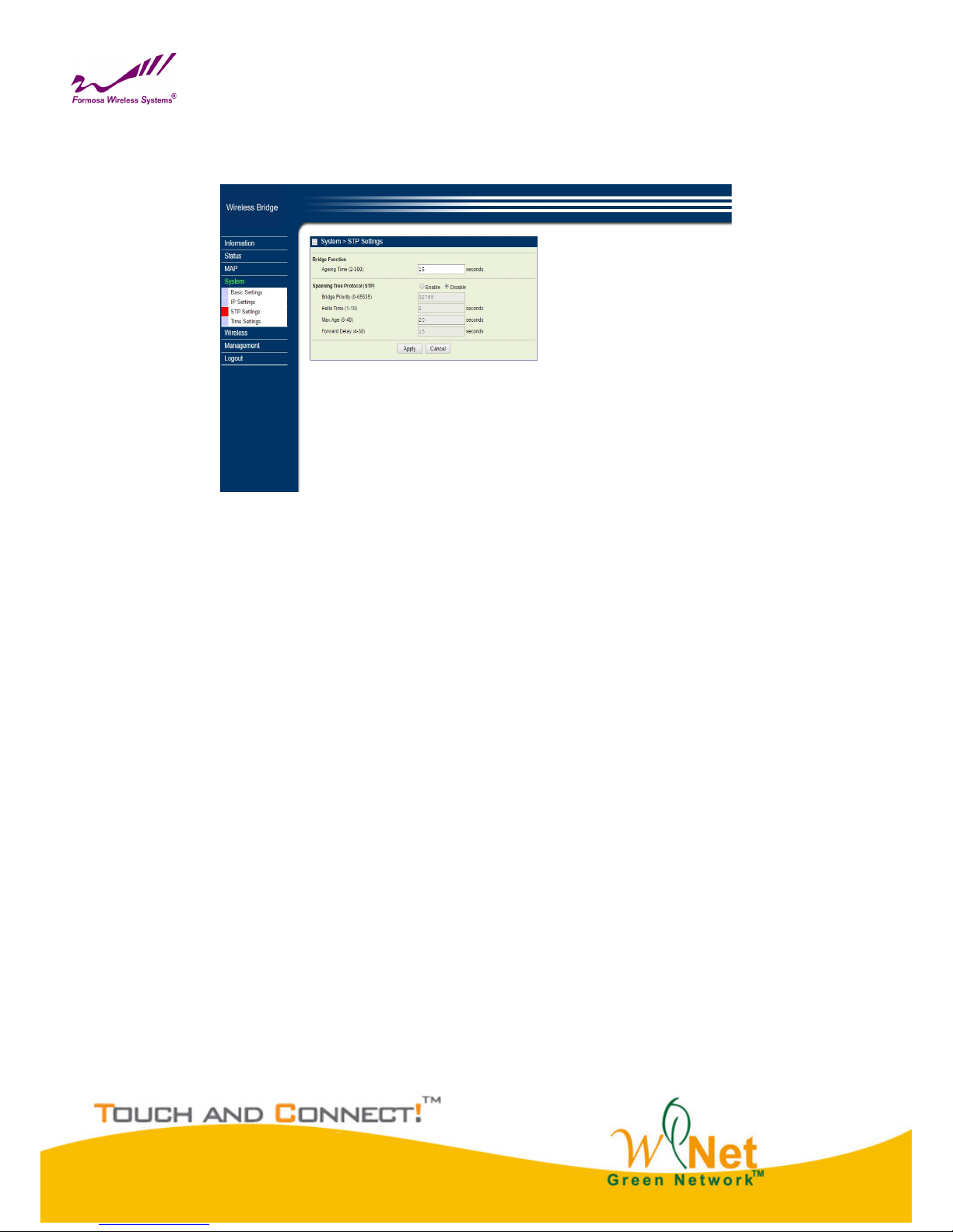
STP Settings
Enabling spanning tree can prevent undesirable loops in the network, ensuring a smooth-running network. By
default, the function is disabled.
STP Settings
Bridge priority : 0 – 65535
Hello Time : 0 – 10 seconds
Max Age : 6 – 40 seconds
Forward Delay : 4 – 30 seconds
Wireless Node Aging : 2– 300 seconds
Page 14
14
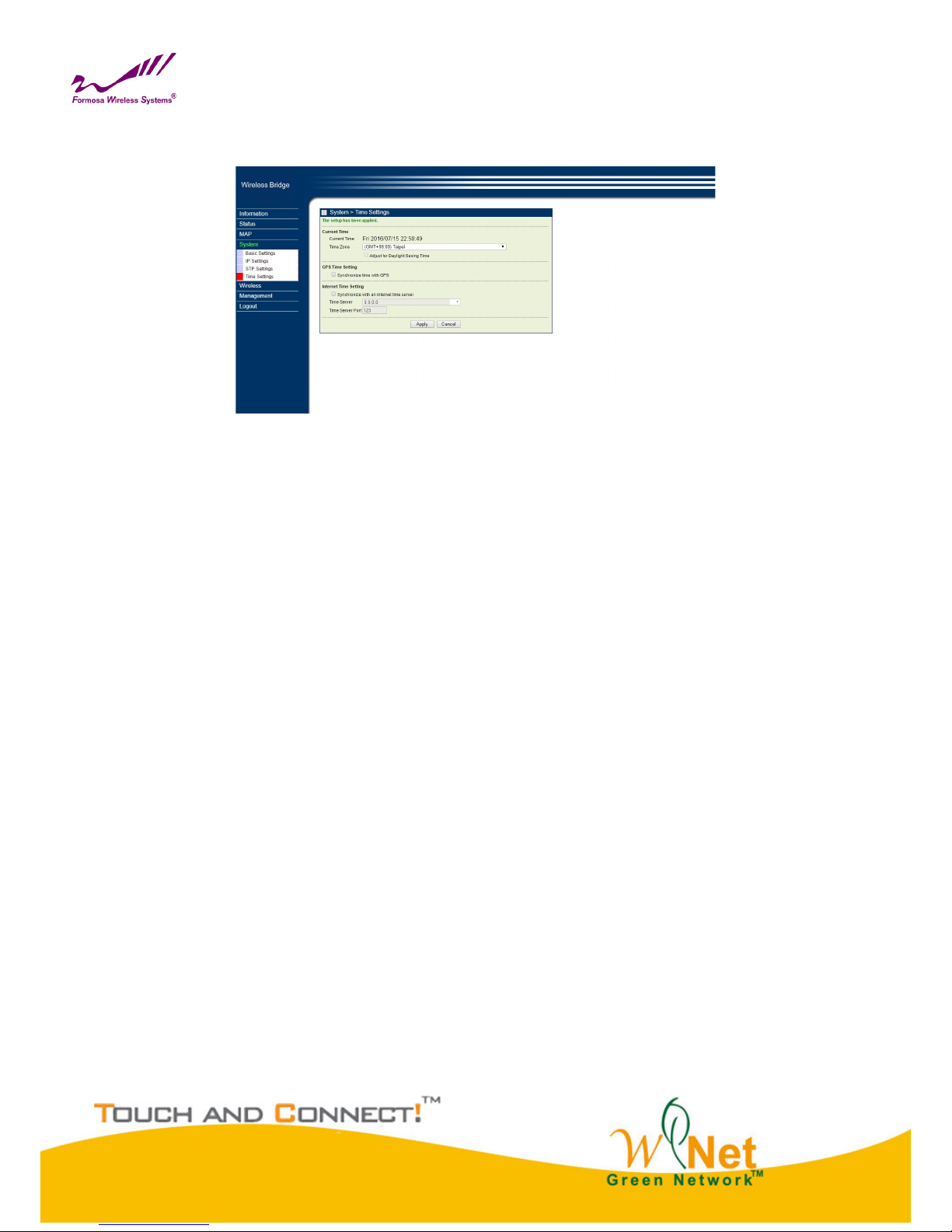
Time Settings
Time Settings
Current Time
This field identifies the current time in your specific time zone.
Time Zone
Select the time zone location for your setting.
GPS Time Setting (Only for GPS Model)
Synchronize time with GPS
Internet Time Setting
Synchronize time with an Internet Time Server
Time Server Port
This field identifies the time server port like 123.
Page 15
15
Chapter 4 Wireless Settings
Basic Wireless Settings
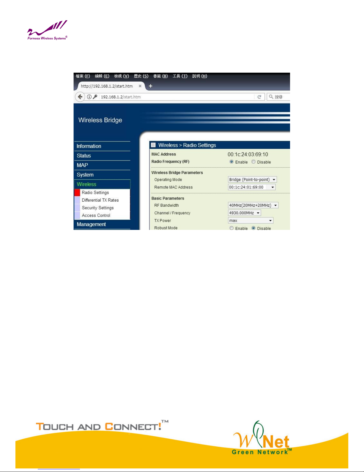
Radio Settings
Page 16

16
Radio Frequency (RF)
RF-Wireless, default is enable.
Operating Mode
Bridge Point-to-Point
Remote MAC Address
Input the MAC address of Remote Bridge.
RF Bandwidth
Decide bandwidth of Radio Frequency. Including 5 / 10 / 20 / 40 MHz, default is 20MHz.
Channel / Frequency
Using different frequency
TX Power
Setting power of TX, default is max.
TX Rate Range
Normally choice transmission rate as “Best”, system will adapt best rate for real environment.
Including
Single Stream Model, SS 64QAM 5/6, SS 64QAM 3/4, SS 64QAM 2/3, SS 16QAM 3/4, SS 16QAM 1/2, SS
QPSK 3/4, SS QPSK 1/2, SS BPSK 1/2
Dual Stream Model, DS 64QAM 5/6, DS 64QAM 3/4, DS 64QAM 2/3, DS 16QAM 3/4, DS 16QAM 1/2, DS
QPSK 3/4, DS QPSK 1/2, DS BPSK 1/2
Advanced Parameters
Coverage Range: Based on Channel Bandwidth, default is 1Km
40MHz, 1-25Km
20MHz,
10MHz,
5MHz,
Page 17
17
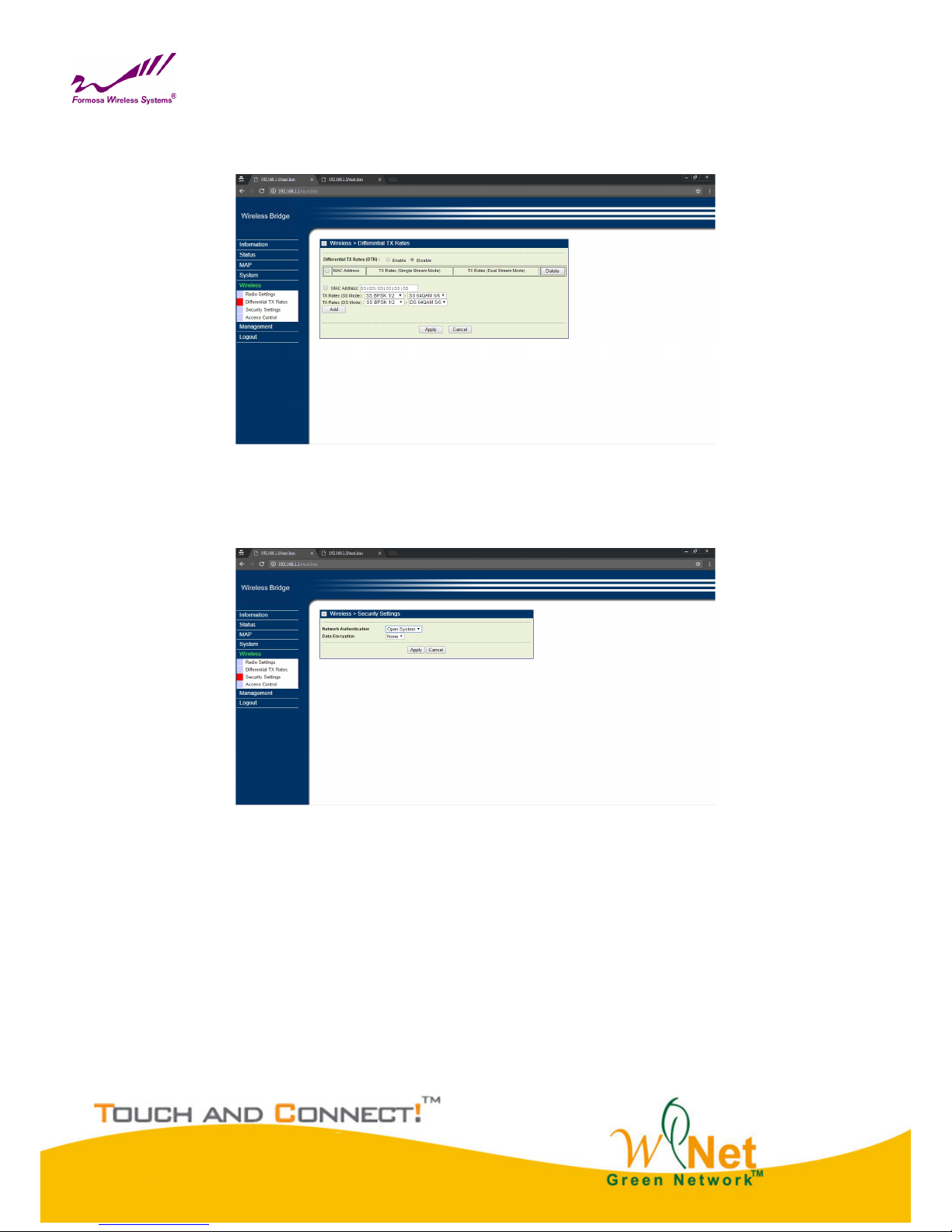
Differential Tx Rates
Setup different Tx modulation for different Clients.
Differential Tx Rates
Security Settings
Security Settings
Network Authentication
There are Open System/ WPA2 PSK to set, default is Open System.
Data Encryption
None/ AES.
Page 18
18
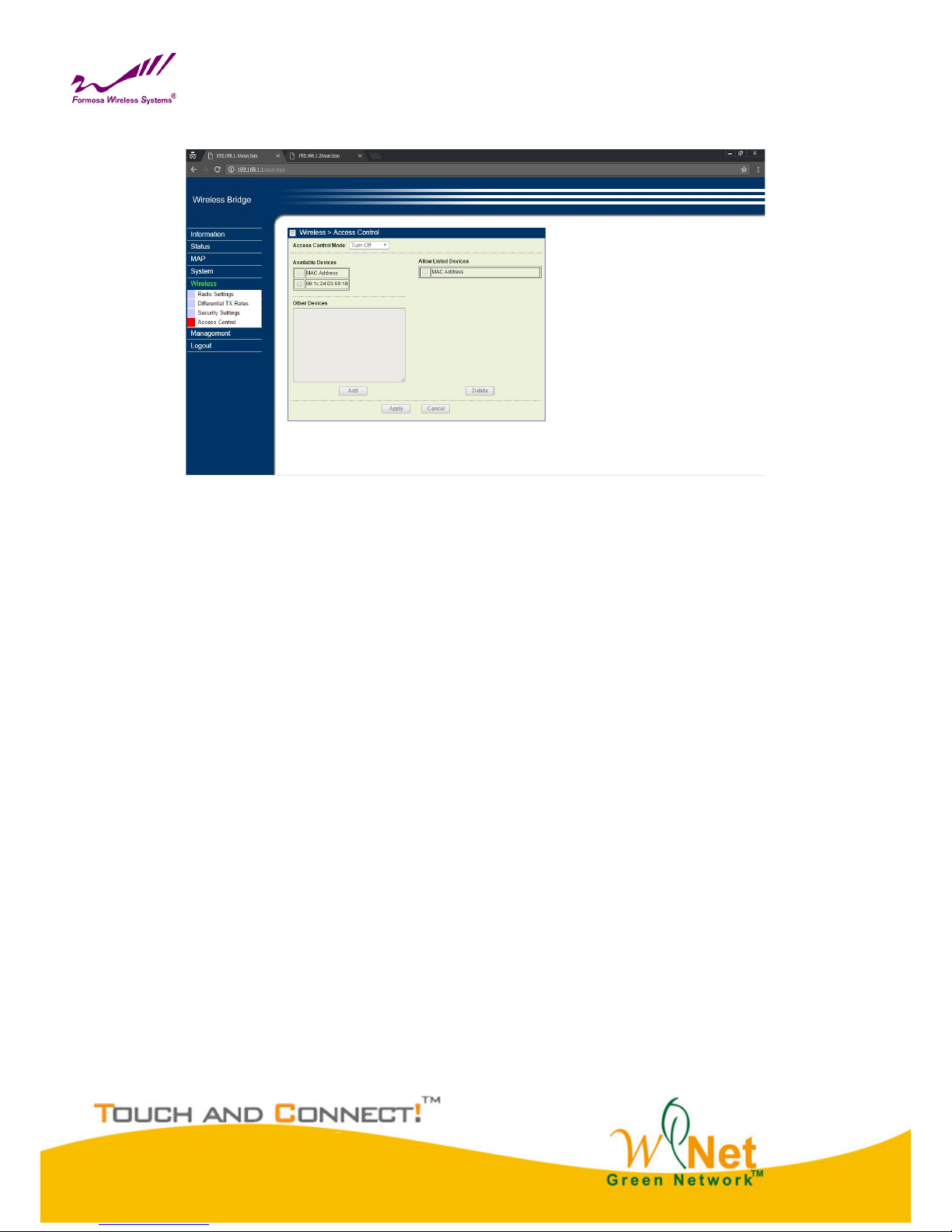
Access Control
Access Control
Access Control Mode
Turn off/Allow/Deny
Select “Allow”, the listing clients are allowed to access the base station. Other clients are blocked.
Select “Deny”, the listing clients are blocked to access the base station. Other clients are allowed.
Page 19
19
Chapter 5 Management
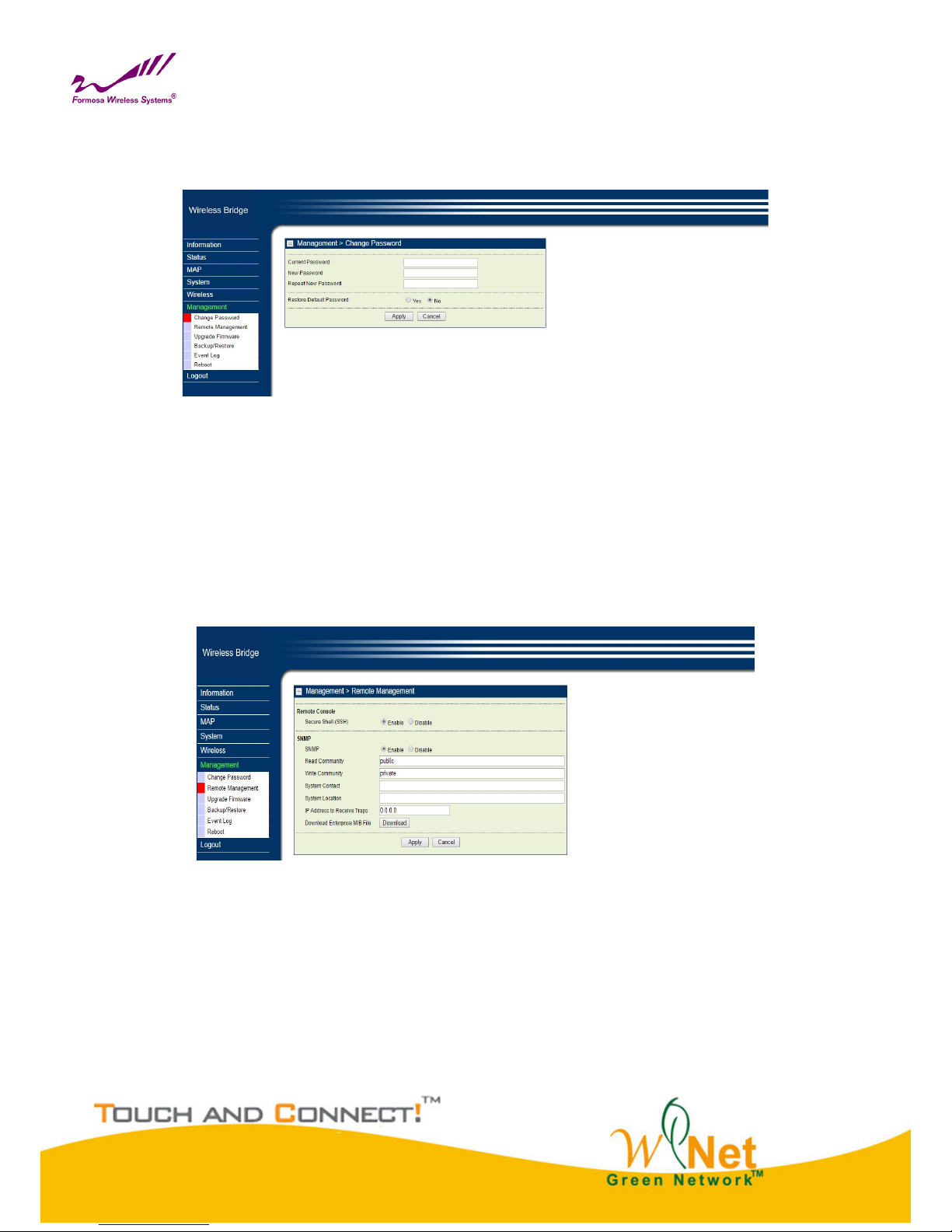
Change Password
Change Password
You can use the Change Password page to change the Bridge administrator's password for
accessing the Settings pages.
To change the password, Type the old password. The default password for the Bridge is:
password. Type a new password and type it again in the Repeat New Password box to confirm it.
Click Apply to have the password changed or click Cancel to keep the current password.
Remote Management
Remote Management
Bridge supports SNMP. If you use SNMP to control bridge. At first you should set SNMP settings
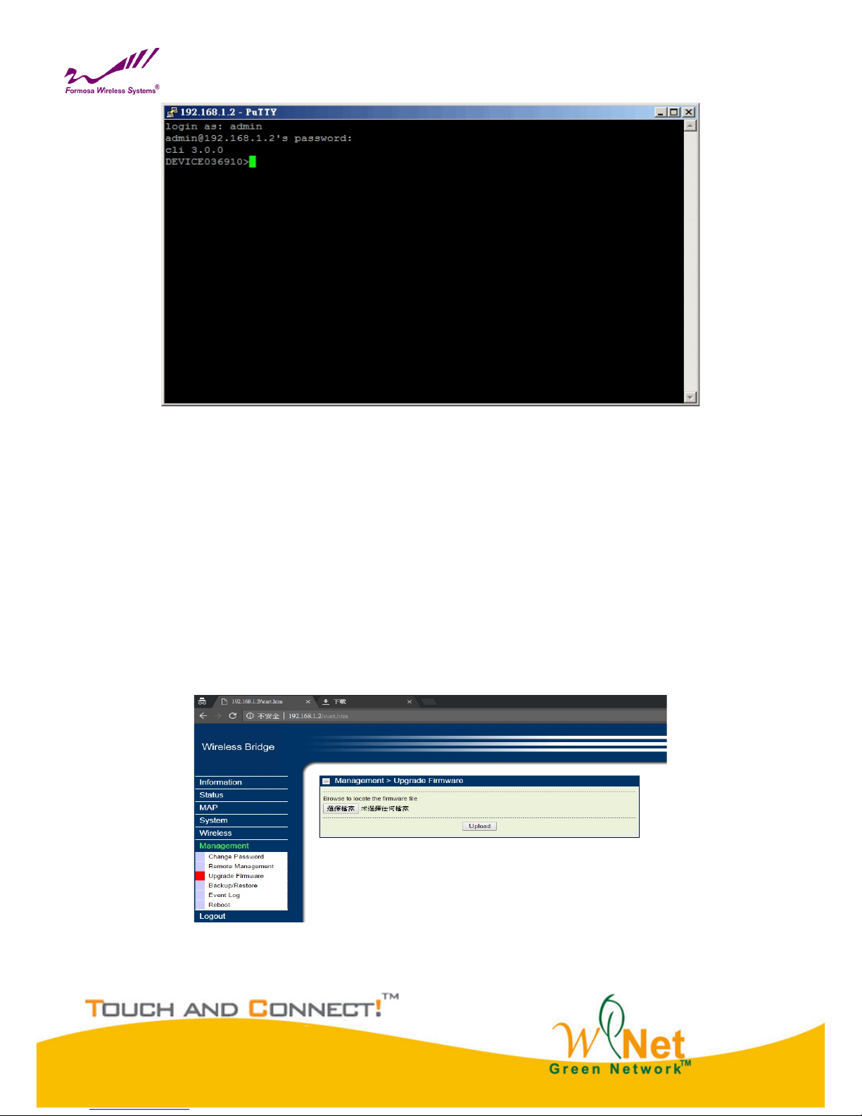
The KW50-O8500 supports CLI too , which could be accessed by Secure Shell (SSH). It is recommended PuTTY
be used to login.
Once the program is downloaded, open up by double-clicking. Note that before using PuTTY, be sure you are able
to connect to the MIMO WiTDM bridge.
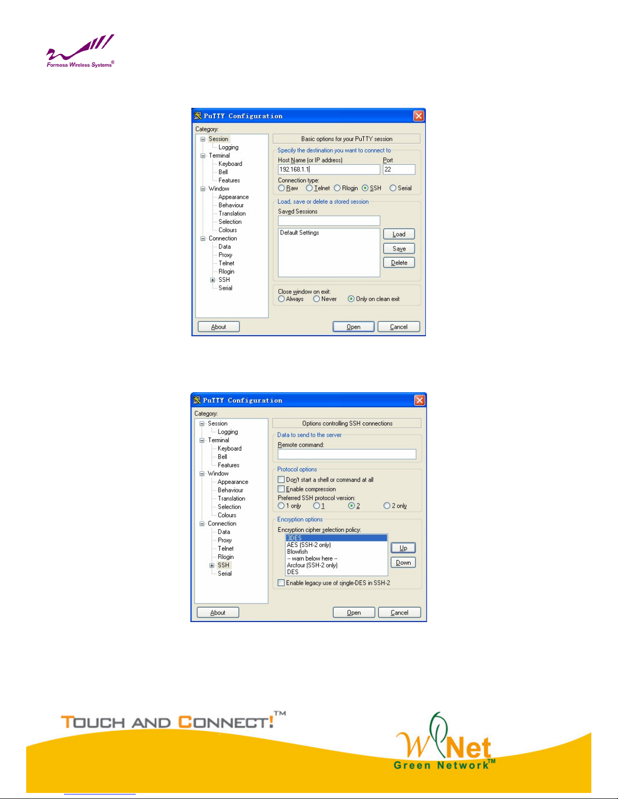
1. Active Secure Shell(SSH). By SSH instruction setting the bridge.
Page 20
20
Double-clicking Putty.
SSH. Enter IP Address of devices, check Protocol as SSH type
PuTTY Configuration
From “Connection” in the lift menu bar, click “SSH”, select”2”as “Preferred SSH protocol version”, make
“3DES” the top position in “Encryption cipher selection policy”.
Figure 16 PuTTY Configuration 2
Click “Open”, a window as below will popup:
Page 21
21
SSH
2.Active SNMP, and control bridge by SNMP network system.
Set Read Community password;Default is public
Set Write Community password;Default is private
Setting Trap Sever IP address
When bridge under abnormal condition, like bridge power failure or reset is usual.
Administrator can easy control device by exception log in Trap Server.
Upgrade Firmware
Via WEB interface to upgrade firmware:
Upgrade Firmware
Page 22
22
1. Open Upgrade Firmware page
2. Click browser button and select the firmware file in local hard disk.
3. Click Upload button.
4. After upgrade, login again and check the software version.
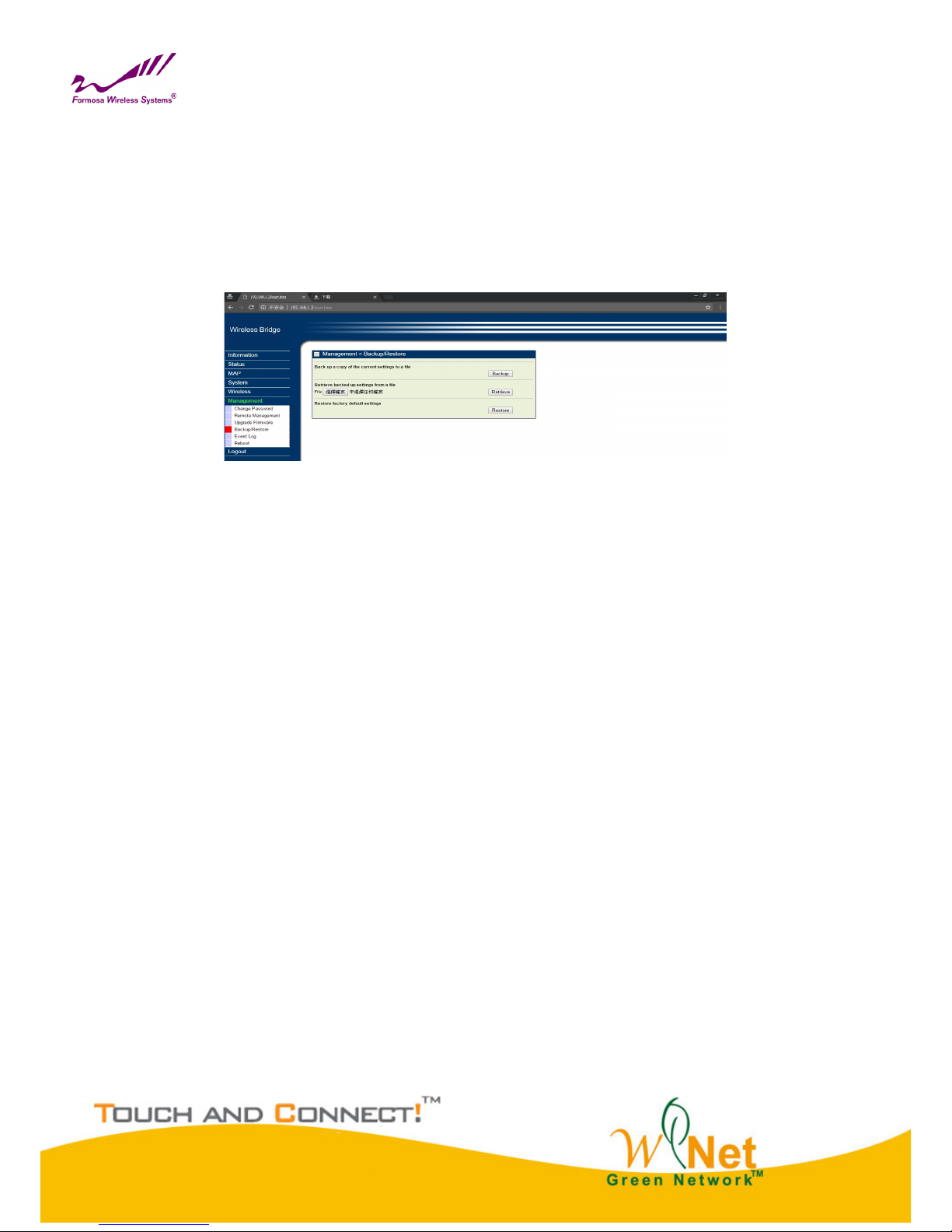
Backup/Restore
Backup / Restore
It would be better to backup settings of device after it work fine, so that you can recover settings quickly when
something go wrong.
1. Open”Backup/Restore” page,click “Backup”, it will pop up a dialog for input path and filename
such as F:\device.cfg, and it will save “device.cfg” in the local disk after that.
2. Open “Backup/Restore” page, click “Browser”,It will pop up a dialog to choice what file you want to
restore, such as “F:\device.cfg”, then click “Retrieve, the settings of the file will be restored back to device,
and it will active for the device after auto reboot.
Page 23
23
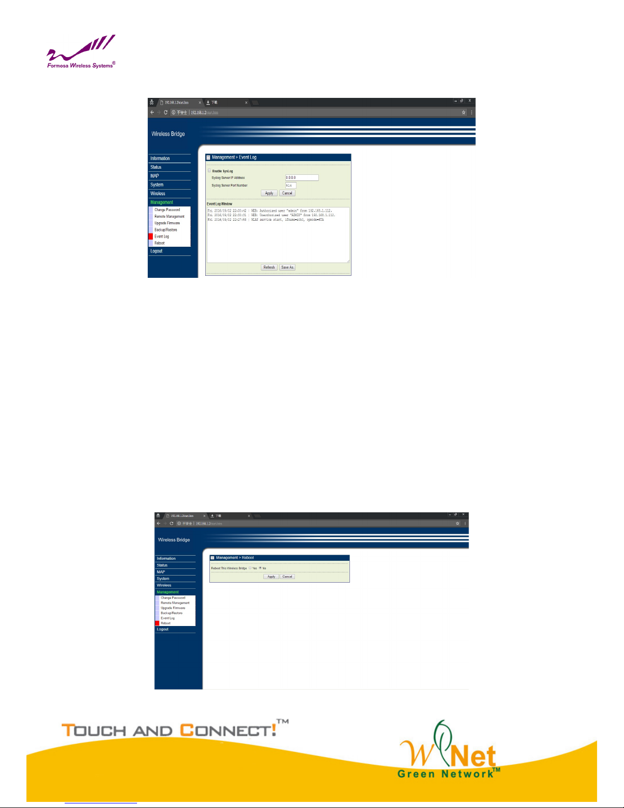
Event Log
Event Log
Event log can show you the event of device, for example, connect, disconnect, reboot of Base station, or
something change about settings. If you need long time observational notes, you can active Syslog. Enter Log Sever IP
address, the port number configured in the SysLog server on your network. By default, it is514
SysLog Server IP address
The Bridge will send all the SysLog to the specified IP address if SysLog option is enabled.
Default: 0.0.0.0
Port
The port number configured in the SysLog server on your network. By default, it is514
Reboot
When you need to reboot the device, you can click the “yes” button and the click “Apply” it will reboot.
Reboot
Page 24

24
Chapter 6 Troubleshooting
FAQ
Q1:How to know the MAC address of the Bridge?
The MAC address is written in a label which is in the bottom of Bridge.
From the General page of WEB configuration, you also can get the MAC address of the Bridge.
Q2:Why two Bridges can not build connection after setting?
1. Check “Operating Mode”, one of bridges is Base Station, another one is CPE.
2. Check “Channel / Frequency” whether is same.
3. Check “Date Encryption” and “Key” whether is same.
Q3:How to adjust output power?
In the Wireless Settings page, you can do it.
Q4:The wireless becomes unstable such as ping timed out and lose pack after a period of well
work?
This situation may the wireless network is disturbed by something, what you can so is
following steps:
1. Check whether every joint point of network is well ( such as Ethernet port, antenna connection. )
2. Change the channel if the Link Test value is not high, excluding other wireless equipment disturb
the Bridge.
3. Restart the Bridge.
4. Default the Bridge and restore last settings.
5. Check the wireless port and Ethernet port environment and virus exist or not.
6. Please call the sales if can not solve problem after all.
Q5:Why can not open WEB page of remote wireless device in local network?
Because this kind of settings will slow the response of remote AP WEB Server, just waiting for several
minutes or restarting remote wireless bridge is a way to solve problem. We suggest you set the Bridge in
local wired Ethernet network.
Page 25

25
Service Support
You can download the latest firmware version from web site if you need. If you have any questions, please contact
us.
Website:http://www.tw-wireless.com/
Support:[email protected]
FEDERAL COMMUNICATIONS COMMISSION INTERFERENCE STATEMENT
This equipment has been tested and found to comply with the limits for a Class B digital
device, pursuant to Part 15 of the FCC Rules. These limits are designed to provide
reasonable protection against harmful interference in a residential installation. This
equipment generates, uses and can radiate radio frequency energy and, if not installed and
used in accordance with the instructions, may cause harmful interference to radio
communications. However, there is no guarantee that interference will not occur in a
particular installation. If this equipment does cause harmful interference to radio or television
reception, which can be determined by turning the equipment off and on, the user is
encouraged to try to correct the interference by one or more of the following measures:
– Reorient or relocate the receiving antenna.
– Increase the separation between the equipment and receiver.
– Connect the equipment into an outlet on a circuit different from that to which the receiver is connected.
– Consult the dealer or an experienced radio/TV technician for help.
CAUTION:
Any changes or modifications not expressly approved by the party responsible for
compliance could void the user's authority to operate the equipment.
This device complies with Part 15 of the FCC Rules. Operation is subject to the following two conditions:
(1) This device may not cause harmful interference and
(2) This device must accept any interference received, including interference that may cause undesired operation.
RF exposure warning
Page 26

26
根據低功率電波輻射性電機管理辦法 :
第十二條經型式認證合格之低功率射頻電機,非經許可,公司、商號或使用者均不得擅自變更頻率、加
大功
率或變更原設計之特性及功能。
第十四條 低功率射頻電機之使用不得影響飛航安全及干擾合法通信;經發現有干擾現象時,應立即停
用,並
改善至無干擾時方得繼續使用。前項合法通信,指依電信法規定作業之無線電通信。低功率射頻電機須
忍受合
法通信或工業、科學及醫療用電波輻射性電機設備之干擾。
2. 根據低功率射頻電機技術規範 :
4.7.9.1 應避免影響附近雷達系統之操作。
4.7.9.2 高增益指向性天線只得應用於固定式點對點系統。
 Loading...