

Page 1

Manual Form 3
Page 2

Installation and Usage Instructions
Form 3
Low Force Stereolithography (LFS) 3D Printer
Original English instructions
Read this manual carefully and keep it for
future reference.
May 2019
REV 01
© Formlabs
Page 3

Table of Contents
1. Preface ..................................................................6
1.1 Read and Retain Instructions ................................................6
1.2 Obtaining Documentation and Information ...................................6
2. Introduction ..............................................................8
2.1 Intended Use .............................................................8
2.2 Technical Specifications ....................................................9
2.3 Product Elements. . . . . . . . . . . . . . . . . . . . . . . . . . . . . . . . . . . . . . . . . . . . . . . . . . . . . . . . . 10
2.4 Understanding the Display ................................................10
3. Safety Warnings ......................................................... 11
3.1 Component and Subsystem Safety ..........................................11
3.2 Personal Protective Equipment (PPE) .......................................13
3.3 Specifications of Tools to Be Used .........................................13
4. Preparation and Set Up ...................................................14
4.1 Arranging the Workspace .................................................14
4.2 Unboxing the Form3 .....................................................14
4.3 Installing the Form 3 ......................................................15
4.4 Connecting the Form 3 ....................................................17
4.5 Transporting the Form 3 ...................................................18
5. Print with the Form 3 ....................................................20
5.1 Operational Environment .................................................20
5.2 Printing ................................................................. 20
5.3 Finishing ...............................................................20
5.4 Managing the Printer ......................................................21
5.5 Emergency and Exceptional Situations .....................................22
6. Maintenance ........................................................... 23
6.1 Inspecting the Product ................................................... 23
6.2 Inspection Tasks Between Prints .......................................... 24
6.3 Monthly Inspection and Maintenance Tasks ................................ 24
6.4 Periodic Inspection and Maintenance Tasks ................................ 24
6.5 Planned Maintenance Procedures ......................................... 26
3
Page 4

7. Troubleshooting and Repair ..............................................28
7.1 Collecting Diagnostic Logs ............................................... 28
7.2 Performing a Factory Reset ............................................... 28
7.3 Cleaning After a Failed Print ..............................................28
7.4 Troubleshooting and Repair .............................................. 29
7.5 Disassembly and Repair ...................................................31
8. Disposal ................................................................ 32
8.1 Guidance for Recycling and Disposal ...................................... 32
9. Index ................................................................... 34
10. Glossary. . . . . . . . . . . . . . . . . . . . . . . . . . . . . . . . . . . . . . . . . . . . . . . . . . . . . . . . . . . . . . . . 35
11. Product Compliance ..................................................... 38
Table of contents | 4
Page 5

WARNING
Read and understand this manual and its safety instructions before using the Form 3.
Failure to do so can result in serious injury or death.
DISCLAIMER
Formlabs has made every eort to make these instructions as clear, complete, and correct
as possible. The information provided in this documentation contains general descriptions
and/or technical characteristics of the performance of the products contained herein. This
documentation is not intended as a substitute for and is not to be used for determining
suitability or reliability of these products for specific user applications. It is the duty of any
such user or integrator to perform the appropriate and complete risk analysis, evaluation, and
testing of the products with respect to the relevant specific application or use thereof. Neither
Formlabs nor any of its aliates or subsidiaries shall be responsible or liable for misuse of the
information that is contained herein. Notify us if you have any suggestions for improvements
or amendments or have found errors in this publication.
Copyright © 2019 by Formlabs. All rights reserved.
support.formlabs.com
TRADEMARKS
All product names, logos, and brands are property of their respective owners. All company,
product, and service names used in this manual are for identification purposes only. Use of
these names, logos, or brands does not imply endorsement.
DOCUMENT REVISIONS
Date Version Document Changes
Mar 2019 REV 00 Initial publication
May 2019 REV 01 Updated compliance and packaging information
Disclaimer | 5
Page 6

1. Preface
Congratulations on purchasing the Form 3. On behalf of the Formlabs team, we thank you for your
purchase. The instructions in this manual provide information for skilled persons to understand safety,
setup and installation, operation, and maintenance of the Form 3 3D printer. These instructions are
intended for anyone who is installing, operating, maintaining, or otherwise interacting with the Form
3. Supervise young or inexperienced users to ensure enjoyable and safe operation.
1.1 Read and Retain Instructions
Read and understand this manual and its safety instructions before using the Form 3. Failure
to do so can result in serious injury or death. Keep all safety information and instructions for
future reference and provide them to subsequent users of the product.
Follow all the instructions. This will avoid fire, explosions, electric shocks, or other hazards that
may result in damage to property and/or severe or fatal injuries.
The Form 3 shall only be used by persons who have fully read and understand the contents
of this usage manual. Ensure that each person who uses the Form 3 has read these warnings
and instructions and follows them. Formlabs is not liable for cases of material damage or
personal injury caused by incorrect handling or non-compliance with the safety instructions.
In such cases, the warranty will be voided.
1.2 Obtaining Documentation and Information
Visit support.formlabs.com to:
• access the latest version of all Formlabs product documentation.
• contact Formlabs to request documentation, usage instructions, and technical information.
•
submit any comments or feedback regarding what is good and what can be improved.
Formlabs values comments from its users.
• request additional training.
1.2.1 Support and Service
Retain a record of the original purchase to request warranty services. Service options depend
on the status of the specific printer’s warranty. Include the serial name of the product when
contacting Formlabs for product support.
Instead of a serial number, all Formlabs machines have a serial name, which is a unique identifier
to track the history of manufacturing, sales, and repair, and to distinguish usage when connected
to a network. The serial name is on the back panel of the machine in this format: AdjectiveAnimal.
service providers of Formlabs products also provide support and service. To the extent that
Formlabs or a certified service provider oers other or extended warranties, the terms of the
separate oer may apply. For products purchased from certified service providers, contact
the original service provider for assistance before contacting Formlabs.
For any support or service requests, including product information, technical assistance, or
assistance with instructions, contact Formlabs Services or a certified service provider:
support.formlabs.com USA
Formlabs, Inc.
35 Medford St.
Somerville, MA, USA, 02143
6
Germany
Formlabs GmbH
Nalepastrasse 18-50
12459 Berlin, Germany
Page 7

1.2.2 Warranty
This product is protected under warranty. Formlabs oers a warranty for all Formlabs-branded
hardware. Unless otherwise expressly stated, the Terms of Service, including the Warranty,
constitute the entire agreement between you and Formlabs with respect to the Service and
any product you purchase from Formlabs and supersedes all prior or contemporaneous
communications, proposals, and agreements, whether electronic, oral, or written, between
you and Formlabs. Read the warranty for more details on the Formlabs warranty for your region:
US formlabs.com/support/terms-of-service/#Warranty
EU (EN) formlabs.com/support/terms-of-service/eu/
EU (DE) formlabs.com/de/support/terms-of-service/eu/
EU (FR) formlabs.com/fr/support/terms-of-service/eu/
Preface | 7
Page 8

2. Introduction
2.1 Intended Use
The Form 3 is a commercial, precision tool intended for use in the additive manufacture of
end-user supplied designs from photopolymer resin. The final performance characteristics
of cured photopolymer resin may vary according to your compliance with the instructions
for use, application, operating conditions, material combined with, end use, or other factors.
In some cases, the additive manufacturing process may inherently result in
NOTICE
WARNING
WARNING
variable performance characteristics between manufacturing runs or within a
specific part. Such variances may not be apparent and may result in unexpected
defects in additively fabricated parts.
You shall independently verify the suitability of additive manufacturing,
stereolithography, the Form 3, and any specific designs or materials employed for the
application and intended purpose before use. In no event shall Formlabs be liable for
any loss, death, or bodily injury that you suer, or that you cause to any third party, in
connection with your use of Formlabs products. To the fullest extent legally permitted
Formlabs EXPRESSLY DISCLAIMS ANY IMPLIED OR EXPLICIT WARRANTY OF
FITNESS for a particular usage, the particular nature and circumstances of said usage
being unforeseen and unforeseeable to Formlabs.
Formlabs is not a manufacturer of medical devices. Formlabs provides tools and
materials that may be used in many applications, but makes no claims as to the
safety or effectiveness of any specific devices made using Formlabs products.
Certain Formlabs products, such as those commonly known in the industry as
“biocompatible” resins, have been engineered to comply with relevant industry
standards. The specific standards and most relevant technical specifications
may be identified within the technical data sheets and have been tested
according to relevant testing protocols for those standards and specifications.
Biocompatible resins are a speciality product, developed for use by medical
professionals, and should be used in accordance with the instructions for use.
WARNING
- Do not modify – The Form 3 is intended for use as-is. Modifying the printer without
explicit approval and directions from Formlabs will invalidate your warranty, and could
potentially ruin the machine and cause you bodily harm.
8
Page 9

2.2 Technical Specifications
Form 3
Shipping
Dimensions
Shipping Weight 22.7 kg (50 lb) 1.5 kg (3.3 lb) 1.4 kg (3.1 lb) 0.67 kg (1.5 lb)
Product Weight 17.5 kg (38.6 lb) 1.35-1.6 kg
3D Printing Technology Low Force Stereolithography (LFS)
Minimum Dimensions for
Convenient Access
Weight 17.2 kg (37.9 lb)
Operating Temperature Auto-heats to 35 °C (95 °F)
Temperature Control Air heated print chamber
Power Requirements 100–240 V ~
Laser Specifications 1 Light Processing Unit
Laser Spot Size (FWHM) 85 microns (0.0033 in)
Radiation Information The Form 3 is a Class 1 Laser product. Accessible radiation is within
Connectivity Wi-Fi, Ethernet, and USB
Ethernet Connectivity RJ-45 Ethernet (10BASE-T/100BASE-TX/1000BASE-T) LAN Port
Wi-Fi Connectivity Protocol: IEEE 802.11 b/g/n
Sound Emission Does not exceed 70 dB(A).
Printer Control Interactive touchscreen
Resin Fill System Automated
Build Volume 145×145×185 mm
Supports Auto-Generated
Printer
57×51×69 cm
(22.5×20×27 in)
Resin Cartridge Form 3
24×20×8 cm
(9.5×8×3 in)
(3-3.5 lb)
Width: 40 cm (15.5 in)
Depth: 53 cm (21 in)
Height: 78 cm (30.5 in)
2.5 A
50/60 Hz
220 W
EN 60825-1:2014 certified
Class 1 Laser Product
405 nm violet laser
250 mW laser
Class 1 limits.
Connect with an Ethernet cable (not included): minimum Cat5, or
Cat5e or Cat6 for 1000BASE-T.
Frequency: 2.4 GHz, 5 GHz
Supported security: WPA/WPA2
5.7×5.7×7.3 in
Removable
Resin Tank
35×30×8 cm
(14×11.8×3.3 in)
0.8 kg (1.8 lb) 0.65 kg (1.4 lb)
Form 3
Build Platform
18×17×8 cm
(7×6.75×3 in)
Introduction | 9
Page 10
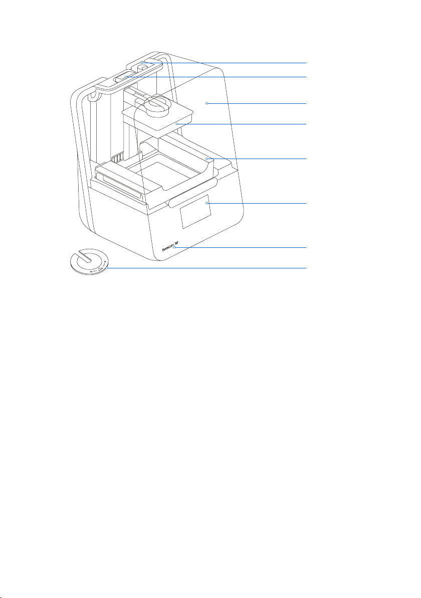
2.3 Product Elements
2.4 Understanding the Display
The Form 3 display includes a touchscreen and status lights.
The touchscreen displays print information, settings,anderror messages. It serves as the user
interface for the Form 3.
The status lights indicate the printer’s state. Refer to messages on the touchscreen to
understand the meaning of the status lights.
For detailed guidance and visual assistance, search on support.formlabs.com.
Resin Cartridge
Status Light
Cover
Build Platform
Resin Tank
Touchscreen
Status Light
Leveling Disc
10
Page 11

3. Safety Warnings
Read and understand this manual and its safety instructions before using the Form 3.
WARNING
DANGER
WARNING
CAUTION
Failure to do so can result in serious injury or death.
Supervise young or inexperienced users to ensure enjoyable and safe operation.
The instructions contain warnings and safety information, as explained below:
Danger indicates a hazard with a high level of risk which, if not avoided, will result in death
or serious injury.
Warning indicates a hazard with a medium level of risk which, if not avoided, could result in
death or serious injury.
Caution indicates a hazard with a low level of risk which, if not avoided, could result in minor
or moderate injury.
NOTICE
WARNING: The laser beam is harmful to the eyes. Avoid direct contact.
DANGER: Isopropyl alcohol is a flammable chemical.
3.1 Component and Subsystem Safety
3.1.1 Laser
Class 1 Laser Product. Only remove the shells of the printer with authorization from
Notice indicates information considered important, but not hazard-related.
WARNING
Formlabs or a certified service provider. Disconnect power before removing the shells.
Accessible radiation is within Class 1 limits. The laser diode used inside the device has the
following specifications:
Diode: Violet (405 nm) Max Output: 250 mW
The laser beam is harmful to the eyes, so avoid direct contact. The Form 3 contains an interlock
system to automatically shut o the laser when the cover is open. If this system is tampered
with or fails, there is a risk of exposure to Class 3B laser light.
Laser Certification: IEC 60825-1:2014 EN 60825-1:2014
FDA performance standards for laser products except for deviations pursuant to Laser Notice
No. 56, dated May 8, 2019
Safety Warnings | 11
Page 12
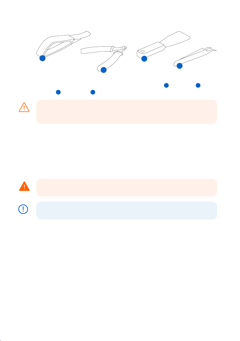
3.1.2 Sharp Tools
1
The accessories include sharp tools such as: a part removal tool , flush cutters ,
a scraper , and tweezers .
Cutting hazard. Using these tools on slippery surfaces (such as a resin-coated build
CAUTION
platform) can result in sudden movement. Orient sharp tools away from yourself,
especially when cutting or scraping.
3.1.3 Resin
Respect Formlabs resin like any household chemical. Follow standard chemical safety
procedures andFormlabs resin handling instructions.
In general, Formlabs resin is not approved for use with food, drink, or medical applications on
the human body. However, biocompatible resins, such as Dental SG Resin, are biologically safe
for specific types and lengths of exposure to the human body. Refer to information about each
specific resin for more detail.
Never ingest resin in liquid or solid form.If swallowed, immediately call a poison
WARNING
center or medical professional.
Always consult theSafety Data Sheet (SDS) as the primary source of information to
NOTICE
understand safety and handling of Formlabs materials.
3 4
3
2
4
1
2
3.1.4 Radio Interference
This equipment has been tested and found to comply with the limits for a Class B digital
device, pursuant to CFR Title 47, Part 15 of FCC Rules. These limits are designed to provide
reasonable protection against harmful interference when the equipment is operated in a
commercial environment. This equipment generates, uses, and can radiate radio frequency
energy and, if not installed and used in accordance with the instruction manual, may cause
harmful interference to radio communications. Operation of this equipment in a residential
area is likely to cause harmful interference, in which case the user will be required to correct
the interference at their own expense.
Changes or modifications to this product not authorized by Formlabs could void the
electromagnetic compatibility (EMC) and wireless compliance and negate your authority
to operate the product.
12
Page 13

This product has demonstrated EMC compliance under conditions that included the use of
compliant peripheral devices and shielded cables between system components. It is important
that you use compliant peripheral devices and shielded cables between system components to
reduce the possibility of causing interference to radios, televisions, and other electronic devices.
Use of controls or adjustments or performance of procedures other than those
CAUTION
specified herein may result in hazardous radiation exposure.
3.1.5 Isopropyl Alcohol (IPA)
Formlabs does not manufacture isopropyl alcohol. Consult the chemical manufacturer
NOTICE
or supplier for detailed safety information.Carefully follow the safety instructions
provided with the isopropyl alcohol that you purchase. Isopropyl alcohol can be
flammable, even explosive, and should be kept away from heat, fire, or sparks. Any
containers holding isopropyl alcohol should be kept closed or covered when not in
use. We also recommend that you wear protective gloves and have good ventilation
when working with IPA.
3.2 Personal Protective Equipment (PPE)
Resin may cause skin irritation or an allergic skin reaction. Wear gloves when handling
WARNING
liquid resin or resin-coated surfaces. Wash skin with plenty of soap and water.
Some methods of support removal may cause small pieces of supports to break away.
CAUTION
Beware of flying debris. Wear eye protection and gloves to protect the skin and eyes.
3.3 Specifications of Tools to Be Used
The Form 3 shall only be used with supplied accessories and additional tools recommended
by Formlabs. Third-party accessories and materials may cause damage.
Purchase additional supplies:
• Keep paper towels in stock to ensure a clean work environment for printing and finishing.
• Clean optical surfaces, including the optical window and the underside of the resin tank,
with PEC*PAD lint free wipes.
• Isopropyl alcohol (IPA, 90% or higher)is the recommended solution for rinsing parts and
cleaning liquid resin after each completed print.
• Connect the printer to a local area network with an Ethernet cable.
• Wear disposable chemical-resistant gloves, such as nitrile or neoprene, when handling
resin or resin-coated surfaces and optics.
• Wear safety glasses when handling liquid resin, when removing printed parts, and when
removing supports from a printed part.
• Clean the cover and outer shells with a non-abrasive microfiber cloth and soapy water
or a general purpose cleaner, such as glass cleaner.
Safety Warnings | 13
Page 14

4. Preparation and Set Up
4.1 Arranging the Workspace
Choose a stable, level workspace to install and operate the Form 3. Reserve the following
minimum dimensions for the most convenient access:
Width: 40 cm (15.5 in) Depth: 53 cm (21 in) Height: 78 cm (30.5 in)
Allow additional space for accessories, such as the Form 3 Finish Kit, Form Wash, and Form Cure.
4.2 Unboxing the Form3
During unboxing, inspect the Form 3 for any damage or missing items. In the case of damage
or missing items, contact Formlabs or the certified service provider.
To unbox the Form 3:
1. Open the box from the top. If the box has a side gate, fold down the side of the box.
2. Use the provided handles to lift the printer, in its carrier tray, out of the box.
3. Remove the printer from the carrier tray and set the printer in its workspace.
4. Remove any additional wrapping and packaging from the outside of the printer.
Remove all packaging material and release the Light Processing Unit (LPU) housing
NOTICE
before connecting power.
To release the LPU housing from its shipping position:
1. Open the printer cover.
2. Read and remove the instructional sticker wrapped around the LPU housing.
3. Locate the latch on the left side of the LPU housing.
4
4.
Turn the thumb screws counter-clockwise by hand. Loosen and remove the two thumb
screws and the latch.
5. Save the latch and screws along with the original printer packaging.
NOTICE
Save the Form 3 packaging for transporting your printer. Original packaging
isrequiredfor warranty service.
4
14
Page 15

4.3 Installing the Form 3
4.3.1 Connect the Cables
Connect the power cable to the printer and the power supply.
Files can be uploaded via USB, Wi-Fi, or Ethernet. For USB, connect the printer to a nearby
computer. For Ethernet, connect the printer to an Ethernet port.
4.3.2 Level the Printer
It is important that the printer sits level so resin does not overflow from the tank during
NOTICE
printing. All four feet must rest on a solid surface to ensure optimal print accuracy.
The Form 3 must be completely level before printing can begin. If prompted, use the leveling
disc to raise or lower each foot of your printer.
To level the Form 3:
1.
Connect the printer to power. If necessary, the touchscreen prompts use of the leveling disc.
a. The initial printer setup sequence includes the leveling procedure.
2. Follow the on-screen instructions to adjust the feet under the printer.
3
3.
Insert the round leveling disc under the designated corner. Push until the leveling disc
clicks onto the foot.
4
4. Rotate the tool clockwise to raise and counter-clockwise to lower the height of the printer.
a. The printer ships with each foot fully retracted. The height of the feet can only be raised
during the initial printer setup.
5. Adjust the feet until the touchscreen indicates the printer is level.
3 4
4.3.3 Insert the Resin Tank and Mixer
Spill hazard. Resin may spill over the tank walls if the resin tank tilts more than 5-10°.
CAUTION
Hold the resin tank level with two hands. To inspect and clean the underside of the
tank, empty the resin tank and/or take care to avoid spilling resin outside the tank.
Resin may cause skin irritation or an allergic skin reaction. Wear gloves when handling
WARNING
liquid resin or resin-coated surfaces. Wash skin with plenty of soap and water.
Preparation and Set Up | 15
Page 16

NOTICE
To install the resin tank:
1. Open the printer cover.
2. Remove the lid of the tank case.
3.
Remove packaging materials from the tank.
4.
Lift the resin tank with one hand on each side.
Avoid contaminating the underside of the
resin tank with fingerprints or liquid resin.
5. Align the resin tank side walls with the left
and right tank carrier rails.
6
6. Push the side handles - toward the back of
the printer and downward - until the side
walls lock into the rails. The resin tank
clicks into place and sits firmly. A sensor
detects the resin tank, and the status
light illuminates.
To insert the mixer:
1.
Orient the mixer with the flexure arms
facing upward and toward the mixer case.
2.
Slide the mixer to the left, into the mixer
case. The flexure arms on each end click
into place.
6
4.3.4 Insert the Build Platform
To insert the build platform:
1
1. Raise the platform lock.
2.
Align the build platform with the platform carrier.
3
3. Push the build platform onto the platform
carrier. A sensor detects the build platform,
and the status light illuminates.
4. Lower the platform lock to secure
the build platform.
16
1
3
Page 17

4.3.5 Insert the Resin Cartridge
1. Close the printer cover.
2.
Shake the cartridge before each print to
ensure the resin is mixed thoroughly. Shake
the resin cartridge approximately every
two weeks during storage to keep the
formula well-mixed for the best print quality.
3.
Remove the orange protective valve cover
from the bottom of the cartridge. Consider
saving the cover to protect the valve
during storage.
Spill hazard. Donotremove the rubber valve at the bottom of the cartridge. This bite
CAUTION
valve controls the release of the resin. Removing the rubber bite valve allows resin to
continuously flow and causes extreme damage to the machine. This damage is not
covered by the warranty.
4. Align the cartridge with the opening in the back of the printer.
5
5. Push down on the cartridge handle until the top of the cartridge is level with the printer. A
sensor detects the resin cartridge, and the status light illuminates.
6. Press open the vent cap, so that the resin tank fills correctly.
4.4 Connecting the Form 3
Connect to the Form 3 to upload and manage
prints over Wi-Fi, USB, and Ethernet. The Form
3 can connect directly to a computer with a USB
cable. For remote uploading and monitoring,
the Form 3 supports both wired (Ethernet) and
wireless (Wi-Fi) connections.Connect PreForm
print preparation softwareto the same localarea network (LAN) as the printer in order to
send a print job.
For a Windows operating system, after installing
PreForm,check to ensure that Bonjour is properly
installed. Bonjour is a piece of third-party software
that is required to connect over Wi-Fi or Ethernet.
See support.apple.com for assistance with
Bonjour. The USB connection can still be used
while the Form 3 is connected to a LAN.
When the Form 3 is connected to a LAN, its current
status and print progress can bemonitored with
Dashboard: formlabs.com/dashboard.
5
Preparation and Set Up | 17
Page 18

4.4.1 Connect with USB
Use the included USB cable for connecting a computer directly to the printer.
1. Plug one end of the USB cable into the back of the Form 3.
2. Connect the other end to a computer’s USB port
4.4.2 Connect with Ethernet
The rear of the unit is equipped with a RJ-45 Ethernet (10BASE-T/100BASE-TX/1000BASE-T) LAN
Port
. Connect to a LAN with an Ethernet cable (not included): minimum Cat5, or Cat5e or Cat6
for 1000BASE-T.
1. Plug one end of the Ethernet cable into the back of the Form 3.
2. Connect the other end to your LAN.
4.4.3 Connect with Wi-Fi
The Form 3’s built-in Wi-Fi (IEEE 802.11 b/g/n) supports WPA/WPA2 security. Use the Form 3’s
touchscreen to configure a wireless network connection.
When connected to an active Ethernet connection or available Wi-Fi network, the Form 3 can
be configured with a static IP address.
To connect with Wi-Fi using a manual IP configuration:
1.
With an established Ethernet or available Wi-Fi connection, open the printer’s Settings
menu on the touchscreen.
a. For Wi-Fi networks, tap Wi-Fi, then the desired wireless network.
b. For Ethernet connections, open Ethernet from the Settings menu.
2. Toggle the Manual IP settings to “ON”.
3. Input the appropriate IP Address, Subnet Mask, Default Gateway, and Name Server.
4.5 Transporting the Form 3
Refer to the Technical Specifications for product weight and dimensions. Keep the packaging
for transportation or shipping. The printer’s complete packaging kit consists of:
• 1 outer carton, cardboard
• 1 lift tray, cardboard
• 1 bottom insert, foam
.
• 1 upper insert, foam
• 1 front insert, foam
NOTICE
NOTICE
Do not ship with resin inside the printer. Resin left inside the Form 3 can damage the
printer in transit, which may lead to additional fees or void the warranty.
To prepare to transport the Form 3:
1. Always remove the build platform, resin tank, and cartridge before moving or packaging
the Form 3 printer.
2. Wipe residual resin from the build platform and store the platform away from sunlight.
3. Store the resin tank in the tank case.
4. Store the cartridge with the vent cap closed and the valve cover installed.
When shipping a printer to Formlabs for service, the build platform, resin tank, power
and USB cables, and other accessories shouldnotbe shipped and will not be returned
after service. The printer’s original packaging is required for warranty service. Contact
other certified service providers for unique guidance on shipping requirements.
18
Page 19

To package the Form 3:
1.
If the printer’s outer cardboard carton has been collapsed, start by reassembling and
securely taping the box’s bottom opening.
2. To secure the LPU housing for shipping:
a. Tap the wrench icon on the touchscreen to open the Settings menu. Find and select the
shipping option to prepare the printer for shipping.
b. Disconnect the power cable.
c. Open the cover and locate the shipping latch mounting points on the left side of the LPU
housing. The LPU housing is in the LPU garage on the right side of the printer.
d. Align the two slots in the latch with the two screw holes in the side of the LPU housing.
The short side of the latch should be oriented away from the front of the printer and point
outwards from the LPU housing.
e. Loosely thread the two thumb screws through the slots and into the LPU housing.
f
f. Slide the latch toward the front of the printer so that it engages with the inside of the
printer shell. If necessary, adjust the position of the LPU by manually turning the lead
screw at the back of the printer cavity. The shipping latch should lay flat against the LPU
housing when it engages with the slot in the printer shell.
g
g.
Tighten both thumb screws to secure the latch. The latch does not move when both
thumb screws are tightened.
f
g
3. Close the printer cover.
4.
Securely wrap the seam between the printer’s top cover and lower shell to maintain
alignment in transit. Wrap with plastic wrap multiple times horizontally and vertically so the
entire printer is covered and the cover is firmly stabilized.
5. Set the bottom foam insert in the cardboard lift tray.
6. Lift the printer to rest on the bottom foam insert.
7. Gently slide the printer into the outer carton.
8. Install the front foam insert to cover the left, right, and front of the printer.
9. Install the upper foam insert. The foam fits exactly around the top of the printer’s cover.
10. Seal each edge of the side opening with adhesive packing tape.
Preparation and Set Up | 19
Page 20

5. Print with the Form 3
5.1 Operational Environment
The operating temperature for Formlabs printers is 64–82 °F (18–28 °C). For optimal printing,
do not exceed this range.
5.2 Printing
5.2.1 Download or Update PreForm
Visit the PreForm product webpage to download the latest version: formlabs.com/tools/preform
Learn to use PreForm from the tutorials available in the software menu.
For detailed guidance and visual assistance, search on support.formlabs.com.
5.2.2 Power the Printer On
Connect the power cable. The printer initiates automatically. To turn o the printer, see 5.4.6
Powering O the Form 3.
5.2.3 Prepare File for Print
Use PreForm software to process STL or OBJ files.
Prepare, save, and upload FORM files to the printer.
5.2.4 Pre-Print Checks
The printer checks the following before each print job:
• Accessories - Sensors check for the proper installation of the resin tank, build platform,
and resin cartridge.
• Temperature - The print chamber and resin heat to around 35 °C. A heating fan blows air
across the heater into the resin tank to heat the resin.
•
Resin - Resin flows from the cartridge into the tank when the cartridge dispense arm squeezes
the valve open. The Form 3 regulates the volume of resin in the tank through a sensor called
the LevelSense board, which is located behind the resin tank. The printer begins to fill the
resin tank once a print starts and maintains the level of resin in the tank during the print.
Printing begins automatically when LevelSense detects the proper amount of resin.
5.2.5 Start or Stop a Print
To start a print, select the job on the touchscreen, and follow the prompts.
To stop a print in progress, select pause, then abort the print.
CAUTION
5.3 Finishing
Moving parts. Do not open the printer cover until the touchscreen indicates the print
is complete.
Part finishing includes all steps after printing. Follow these steps to bring a 3D model from a
digital file to a functional, printed part:
1. Print: Prepare the FORM file in PreForm, upload and start the print, and then monitor the
print progress on Dashboard.
2.
Wash: Use Form Wash or the Finish Kit to rinse the remaining liquid resin from printed
parts’ surfaces.
3. Dry: Allow at least 30 minutes for isopropyl alcohol (IPA) to fully evaporate after washing.
20
Page 21

IPA is flammable. Keep containers closed, and keep out of the reach of children.
DANGER
4. Post-Cure: Use Form Cure to expose printed parts to light and heat to stabilize the parts
for performance.
5.
Post-Process: Remove supports, then use sanding, priming, or painting to improve
presentation, or use other equipment to create molds from printed parts.
5.4 Managing the Printer
5.4.1 Connect to the Form 3 with Dashboard
Dashboard (formlabs.com/dashboard) allows individuals and teams to remotely monitor
Form 3 printers, track material usage, and explore past and future Formlabs purchases.
Register the Form 3 to Dashboard through the touchscreen on the printer. Once the Form
3 is registered to Dashboard and Dashboard logging is enabled on the printer, the Form 3
will send data to Dashboard as long as the printer’s Wi-Fi or Ethernet connections are able
to access the internet.
5.4.2 Change Resin Types Between Prints
When changing resin types, always change both the tank and the cartridge. Remove the
cartridge before removing the tank to prevent the cartridge valve from dripping resin into
the printer.
See 6.5.2 Maintain the Resin Tank and 6.5.4 Remove and Replace the Cartridge.
5.4.3 Manage or Delete Uploaded Prints
• To start an uploaded file:
Confirm the resin tank and cartridge match the file’s resin type and version.
°
Tap the file name from the queue.
°
• To delete a print from the queue:
Tap the file name from the queue.
°
Tap delete.
°
5.4.4 Fine Tune the Form 3
Adjust Fine Tuning settings to correct any consistent, small-scale dimensional errors or to
mitigate model adherence issues.
The Z Fine Tuning setting changes the “Z Oset” value to adjust the distance between the
build platform and the bottom of the resin tank.
The X/Y Fine Tuning option adjusts the scaling factor in the printer’s X and Y axes.
5.4.5 Check and Maintain the Resin Temperature
The Form 3 heats resin to a set temperature before starting a print. View the print chamber’s
current temperature on the touchscreen.
The print chamber is heated by hot air blown out of the tower behind the resin tank. The warm
air in the print chamber heats the resin, and the air temperature is sensed by a thermal sensor
at the air intake. The Form 3 automatically pre-heats and maintains a consistent print chamber
temperature before and between print jobs.
5.4.6 Power Off the Form 3
Turn o the Form 3 completely when moving or storing the printer and to conserve power. To
turn o the Form 3 completely, disconnect the power cord from thepower source.
Print with the Form 3 | 21
Page 22

5.5 Emergency and Exceptional Situations
Formlabs has made every eort to provide updated Safety Data Sheets (SDS) for every resin
product, in accordance with the latest government guidelines. Always consult the SDS as
the primary source of information to understand safety and handling of Formlabs materials.
In an emergency involving resin, always refer to the Safety Data Sheet (SDS) and/or
WARNING
seek help from a medical professional.
When handling IPA, always consult the safety Data Sheet (SDS) from the IPA supplier as the
primary source of information. Handle IPA with gloves in a well-ventilated area. Keep away
from heat, sparks, and open flame. IPA evaporates rapidly, so keep the rinse tub and bottles
closed whenever possible.
Promptly clean and inspect the printer after a resin spill to minimize any cosmetic or functional
damage to the printer. If you have experienced an accidental resin spill, document the problem
with photos and clean the printer as best as possible. Contact Formlabs or a certified service
provider as soon as possible.
22
Page 23

6. Maintenance
• Formlabs provides instructions to advise skilled and non-skilled persons in
WARNING
6.1 Inspecting the Product
6.1.1 Before Each Print
installing, operating, and maintaining the Form 3. The Form 3 shall only be
maintained by a qualified and trained person.
Do not open the Form 3 and/or investigate internal components unless under
the guidance of Formlabs or a certified service provider. Contact Formlabs or a
certified service provider for any additional guidance.
• Unauthorized disassembly or repair procedures may damage the printer and
void the warranty.
• Wear personal protective equipment when performing maintenance tasks. Use
tools only as described.
• Disconnect the power cable before maintenance. Moving parts and lead screws
present crushing and tangling hazards.
Inspect Refer to:
Installation Environment Operational Environment 5.1
Resin Cartridge Bite Valve Inspect the Bite Valve 6.2.1
Resin Tank Interior Maintain the Resin Tank 6.5.2
6.1.2 Monthly
Inspect Refer to:
Resin Cartridge ID Chip and Reader Protect the ID Chips on the Resin Tank and Resin
Resin Tank Spring Fingers Protect the ID Chips on the Resin Tank and Resin
Resin Tank Exterior Maintain the Resin Tank 6.5.2
6.1.3 Every 3 Months
Inspect Refer to:
Cover Inspect the Cover 6.4.1
Display Inspect the Display 6.4.2
Drip Catcher Inspect the Drip Catcher 6.4.3
Shells Inspect the Shells 6.4.4
X- and Z-axis Lead Screws Inspect and Lubricate the X- and Z-axes 6.4.5
Section:
Section:
6.3.1
Cartridge
6.3.1
Cartridge
Section:
Maintenance | 23
Page 24

6.2 Inspection Tasks Between Prints
6.2.1 Inspect the Bite Valve
Thebite valveis located on the underside of the resin cartridge. This flexible seal regulates resin
dispensing. Resin flows out of the opening in the center of the bite valve when thecartridge
dispense armsqueezes the valve open.
When switching to a dierent resin cartridge, inspect the bite valve for any cured resin or damage.
6.2.2 Inspect the Resin Tank Interior
See 6.5.2 Maintain the Resin Tank.
6.3 Monthly Inspection and Maintenance Tasks
6.3.1 Protect the ID Chips on the Resin Tank and Resin Cartridge
ID (identification) chips on resin tanks and resin cartridges detect, track, and match the resin
type in the tank with the proper resin cartridge. The ID chip is on the underside of each tank
frame and on the bottom of the cartridge near thebite valve.
Protect the ID chips, the tank carrier, the tank spring fingers, and the cartridge spring fingers from
resin contamination or damage. Cured resin or contamination prevents the printer from properly
identifying a cartridge or resin tank during insertion or use. Avoid exposing the cartridge ID chip,
the resin tank ID chip, the tank carrier, and the tank spring fingers to liquid resin.
6.3.2 Clean the ID Chips or Spring Fingers
To remove resin from the ID chip or spring fingers:
1. Apply a small amount of clean IPA to the tip of a cotton swab.
2. Rub the tip of the cotton swab onto the silver pads on the ID chip or onto and around the
spring fingers. The cured resin or contamination dissolves.
Do not bend the spring fingers when cleaning. Ensure that any IPA on the ID chip
NOTICE
dries completely before continuing printing.
6.3.3 Inspect the Resin Tank Exterior
See 6.5.2 Maintain the Resin Tank.
6.4 Periodic Inspection and Maintenance Tasks
6.4.1 Inspect the Cover
Visually inspect the cover for traces of resin, cracks, or other damage.
Clean the cover with a non-abrasive microfiber cloth and soapy water or a general purpose
cleaner, such as glass cleaner.
In the case of a crack that allows light to pass through the cover, replace the cover. See 7.5
Disassembly and Repair.
6.4.2 Inspect the Display
Visually inspect the display for any traces of resin. Clean the display with a non-abrasive
microfiber cloth and general purpose cleaner, such as glass cleaner.
6.4.3 Inspect the Drip Catcher
Disconnect the power cable. Moving parts and lead screws present crushing and
WARNING
tangling hazards.
24
Page 25

Remove the build platform, resin tank, and resin cartridge to access the drip catcher, which
is the area below the resin tank spout or under the resin cartridge dispensing mechanism.
Visually inspect the drip catcher. Clean any traces of resin or contamination with isopropyl
alcohol (IPA) and paper towels.
6.4.4 Inspect the Shells
Visually inspect the rear, front, side, and top shells for traces of resin or other damage. Clean
any traces of resin or contamination with soapy water and paper towels.
6.4.5 Inspect and Lubricate the X- and Z-axes
Disconnect the power cable. Moving parts and lead screws present crushing and
WARNING
tangling hazards.
Wear clean gloves to handle the lead screw and lubricant.
To inspect the X-axis:
1. Manually rotate the X-axis lead screw.
2. As the LPU housing moves right and left, listen, look, and feel to check for areas that emit
noise or where the carrier sticks or move less smoothly.
3.
Visually inspect the X-axis to ensure that no debris or foreign objects obstruct the lead
screw or path of motion.
4. Visually inspect the X-axis to ensure that lubricant covers the full length of the threads.
To inspect the Z-axis:
1. Manually rotate the Z-axis lead screw.
2. As the build platform carrier moves up and down, listen, look, and feel to check for areas
that emit noise or where the carrier sticks or move less smoothly.
3.
Visually inspect the Z-axis to ensure that no debris or foreign objects obstruct the lead
screw or path of motion.
4. Visually inspect the Z-axis to ensure that lubricant covers the full length of the threads.
In the case that the screw is missing lubricant or if the X- or Z-axis emits intermittent noises
when printing, lubricate the lead screw.
To lubricate the X- or Z-axis lead screw:
1. Remove the build platform and resin tank.
2. Place a clean low-fiber paper towel over the tank carrier and LPU housing.
3. Remove old and dirty grease from the lead screw using a paper towel.
4. Apply a light layer of lithium grease evenly along the lead screw. Apply the lubricant
directly from the container or by dabbing lubricant onto the lead screw with a
gloved hand.
5. Manually rotate the lead screw.
a. Z-axis: As the build platform carrier moves up and down, listen, look, and feel to check
for areas that emit noise or where the carrier sticks or moves less smoothly.
b. X-axis: As the LPU housing moves right and left, listen, look, and feel to check for areas
that emit noise or where the carrier sticks or moves less smoothly.
6. Wipe excess lubricant from the leadscrew with a microfiber cloth or low-fiber paper towel.
7. Reconnect the power cable.
Maintenance | 25
Page 26

6.5 Planned Maintenance Procedures
For detailed guidance and visual assistance, search on support.formlabs.com.
Maintenance tasks shall be done according to the following plan:
Task Frequency
Update the firmware When PreForm indicates a new firmware version
Replace the resin tank Replace when wear on the film begins to aect
Replace the resin cartridge When the cartridge is empty, after 1 liter of printing
Filter the resin
6.5.1 Update Form 3 Firmware
Formlabs regularly releases updated firmware to fix bugs and improve functionality. Review
the PreForm and firmware release notes to learn more about the improvements that come
with each version’s release.
6.5.2 Maintain the Resin Tank
Spill hazard. Resin may spill over the tank walls if the resin tank tilts more than 5-10°. Hold
CAUTION
the resin tank level with two hands. To inspect and clean the underside of the tank, empty
the resin tank and/or take care to avoid spilling resin outside the tank. Sharp and metal tools
can damage the dual-layer film in the resin tank and aect print quality. Do not use sharp or
metal tools in the resin tank. Use only the tank tool to clean the inside of the resin tank.
To inspect the Resin Tank interior:
1. Use the tank tool to inspect the resin and the film. See 7.3 Cleaning After a Failed Print,
steps 1-3.
2. Check for the following issues that may lead to print failures or any excessive wear that
requires replacing the tank:
• cured resin on the film
• debris or failed prints in the resin
• punctures, cuts, or gouges in the film
3. Check that the mixer and float are properly installed in the tank case. See 4.3.3 Insert the
Resin Tank and Mixer.
4.
Follow cleaning instructions to remove cured resin, failed prints, debris, and settled pigment. For
moderate wear or scratches on the film, use the Layout toolbar in PreForm to print outside the
worn or scratched area. In the case of excessive wear or scratches on the film, replace the tank.
To inspect the Resin Tank exterior:
1. Visually
inspect the film on the underside of the tank for fingerprints, dust, contamination,
and scratches, which cause the laser light to diuse and lead to print failures or inaccuracies.
2.
Use cleaning instructions to remove any fingerprints, dust, or contamination on the film
before printing.
To clean the Resin Tank:
• Print failures:
See 7.3 Cleaning after a Failed Print.
°
Section:
is available
print quality
When you can visually see particles in the tank
26
Page 27

• Debris or contamination in the resin:
See 6.5.3 Filter the Resin.
°
Clean, debris-free resin helps avoid print failures, which may damage the tank.
°
•
Settled pigment in the resin: Resin pigment can settle onto the film. To supplement the
mixer’s function, slide the tank tool against the film to remove settled pigment.
• To clean the underside of the film:
1. Apply a small amount of clean IPA to a PEC*PAD.
2. Wipe the surface of the film to remove contamination or resin.
• To clean the Resin Tank frame exterior:
3. Use a paper towel to clean resin from the exterior of the tank frame.
4. Keep the sides of the tank clean and free of resin.
5.
Avoid resin on the underside of the film, because the contamination may result in print
failures and/or damage to the roller holder.
To replace the Resin Tank:
6. Remove the build platform.
7. Hold the side walls of the resin tank.
8. Gently pull - away from the printer and upward - the resin tank to release the tank from
the tank carrier.
9. Store the resin tank in the tank case with the lid installed. To dispose of the resin tank, see
8.1.1 Disposal of resin.
10. To install a new resin tank, see 4.3.3 Insert the Resin Tank and Mixer.
6.5.3 Filter the Resin
For detailed guidance and visual assistance, search on support.formlabs.com.
To filter resin:
1. Suspend the paint or oil filter (with a “fine” or ~190 micron mesh size) above an opaque
plastic container suitable for storing resin. Use a ring stand to reduce the risk of spilling resin.
2. Wear gloves to remove the tank and mixer. Place the mixer aside on a protected surface.
3. Hold the edge of the tank, taking care not to touch the tank’s film.
4. Tilt the resin tank with the spout aligned directly above the filter.
5. Pour the resin through the filter, into the disposable container.
6. Gently scrape the surface of the resin tank to pull resin toward the spout.
7. Once all resin passes through the filter, pour the resin back into the tank.
To dispose of the used filter, see 8.1.1 Disposal of resin.
6.5.4 Remove and Replace the Cartridge
For detailed guidance and visual assistance, search on support.formlabs.com.
To replace the cartridge:
1. Press the vent cap closed.
2. Hold the cartridge handle.
3. Lift the cartridge out of the printer.
4. Store or dispose of the cartridge. For detailed guidance and visual assistance, search on
support.formlabs.com.
5. To install a new resin cartridge, see 4.3.5 Insert the Resin Cartridge.
NOTICE
Store the cartridge upright with the valve cover installed to protect storage surfaces from resin.
Maintenance | 27
Page 28
7. Troubleshooting and Repair
For detailed guidance and visual assistance, search on support.formlabs.com.
7.1 Collecting Diagnostic Logs
The Form 3 maintains diagnostic logs to provide detailed information about the printer that may
expedite issue investigation. After experiencing any error or unusual behavior on the Form
3, include the diagnostic logs with other relevant observations and details when contacting
Formlabs Support.
The options for sharing diagnostic logs vary depending on the printer’s connection type.
7.2 Performing a Factory Reset
Do not perform a factory reset immediately before contacting support. The stored
NOTICE
7.3 Cleaning After a Failed Print
WARNING
NOTICE
diagnostic information may be helpful for Formlabs to assist with troubleshooting.
A factory reset erases diagnostic information and custom settings, including Fine Tuning
settings, uploaded jobs, and networked connections.
Resin may cause skin irritation or an allergic skin reaction. Wear gloves when handling
liquid resin or resin-coated surfaces. Wash skin with plenty of soap and water.
Sharp and metal tools can damage the film in the resin tank and aect print quality.
Do not use sharp or metal tools in the resin tank. Use only the tank tool to clean the
inside of the resin tank.
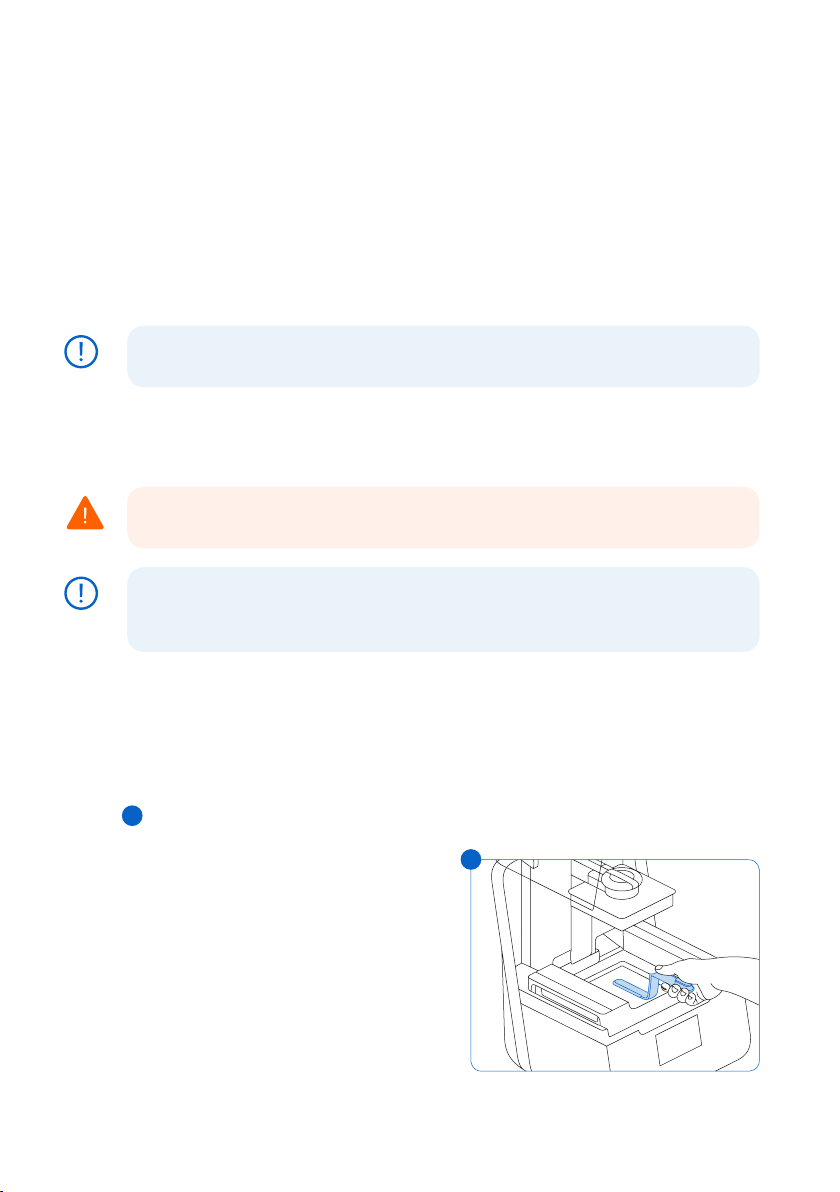
A failed print may leave small, partially-cured pieces of resin floating in the tank or hard cured resin stuck
to the film in the base of the tank. Inspect the tank after every print. Remove debris after a failed print.
Optional: Remove the resin tank from the printer. Place the resin tank in the tank case.
1. To remove debris from the resin tank:
2. Separate the top and bottom parts of the tank tool. Place the top part aside.
3. Prepare several paper towels nearby to collect cured and uncured resin.
4
4. Rest the long edge of the tank tool on the film inside the resin tank. Skim the surface of the
film. Search for obstructions that indicate cured resin stuck to the film.
a. To remove cured resin:
b.
Slide the long edge of the tool under the
4
edge of the cured resin.
c.
Pry with moderate pressure. Slide or
pry from dierent angles or increase
pressure to detach cured resin from the
film’s surface. The cured resin detaches.
d. Rest the cured resin on the blade of the
tank tool.
28
Page 29

e. Lift the cured resin out of the resin tank.
I. If the tank tool cannot hold the cured resin:
2. Attach the top part of the tank tool to the bottom part.
3. Squeeze the cured resin between the two ends.
f. Rest the cured resin on the paper towel.
5. Dispose of cured resin. See 8.1.1 Disposal of resin.
6. Clean the tank tool and work area.
To clean the tank tool:
1. Apply clean IPA to a clean paper towel.
2. Wipe the surface of the tank tool to remove resin.
3. Allow the tank tool to air dry.
Or:
1. Rest the tank tool in the Form Wash basket.
2. Set Form Wash to clean for 5 minutes. Increase the time for solvent that is less fresh.
3. Allow the tank tool to air dry after washing.
7.4 Troubleshooting and Repair
In the case of an error or abnormal activity with the Form 3, reference the following errors,
causes, and proposed solutions. Complete the initial troubleshooting steps and carefully
document all results. Contact Formlabs or a certified service provider for additional assistance.
7.4.1 Resolve Abnormal Functions During Print Set-Up
Error Cause Solution
The bite valve
does not
dispense resin.
The orange
“Print” icon is
not available
in PreForm.
Missing Resin
Tank; Missing
Cartridge
The silicone
material has
sealed itself.
Resin may cure
over the bite
valve opening.
The printer may
not be properly
connected
to the same
local network.
The ID chip(s) is
dirty or missing.
To troubleshoot a closed bite valve:
1. Close the vent cap and remove the resin cartridge from
the printer.
2. Turn the cartridge upside down to inspect the bite valve.
3. Squeeze the valve a few times to open up the seal and
enable resin flow.
4. If squeezing the valve does not enable resin flow, carefully
use the tip of the tweezers from the Finish Kit or Form Wash
to push through the opening to enable resin flow.
5. If the bite valve seal remains closed after troubleshooting,
contactFormlabs Supportfor additional help. Submit
photos of the bite valve seal with your request.
Consider the following:
• Check to see that you do not have other open instances
of PreForm.
• Save any files before restarting PreForm.
• Re-connect your printer to establish a proper connection.
1. Fully remove the resin tank and/or cartridge.
2. Check the ID chip on the resin tank and/or cartridge to
ensure the ID chip is present and clean.
3. Clean the ID chip, if necessary. See 6.3.1 Clean the ID
Chips or Spring Fingers.
4. Re-insert the resin tank and/or cartridge.
Troubleshooting and Repair | 29
Page 30

7.4.2 Resolve Print Failures and Errors
Print failures can manifest in dierent ways and originate from dierent causes. Check the
model’s configuration in PreForm, the cleanliness of the optical surfaces, and the printer’s
operating condition according to 6 Maintenance and 7 Troubleshooting, including the
proposed solutions below.
If print failures persist after following these steps, contact Formlabs or a certified service
provider for additional guidance. In order to introduce a known good variable to isolate any
printing issues, run a Formlabs test print, for which the file is available on support.formlabs.
com. Provide clear, focused photographs of the test print to help diagnose the issue.
Error Cause Solution
Delamination
Peeling or separation
between printed layers
Pieces of cured parts
floating in the resin tank
Non-Adherence
Prints either partially
attached to or
completely non-existent
on the build platform
Overcompression
The base printed onto
the build platform is
thinner than expected
and/or very dicult
to remove.
Poor Surface Finish
Cured or partially cured
resin forms thin, shelflike structures that hang
horizontally from a print.
OR
A rough - uneven or
bumpy - surface texture
forms on one or both
sides of an otherwise
successful print.
Model orientation, layout, and/or
support issues
A print that has been paused for
a long time
An older resin tank
A loose build platform
Contaminated optical surfaces
Printing without supports
The first layer of the part on the
build platform is too small to
withstand peel forces.
Debris/damage in resin tank
Contaminated optical surfaces
Build platform height requires
adjustment
The initial layers fail to cure
properly, due to insucient
space between the build platform
and the film in the resin tank.
Diused laser light spreads
the cure area beyond the
appropriate limits for each layer
outline, due to:
Expired resin;
Debris/damage in the resin tank;
Contaminated optical surfaces;
or, Restricted resin flow due to
improper model orientation or
overly dense supports
Consider the following:
• Check the model in PreForm.
• Check for pauses in printing.
• Check the resin tank for debris
or damage.
• Check cleanliness of optical surfaces.
• Check the build platform’s stability.
Consider the following:
• Print with a base and supports.
• Check the print’s surface area.
• Check the resin tank for debris
or damage.
• Check cleanliness of optical surfaces.
• Check the build platform height.
• Decrease (“-”) the Z Oset value to
lower the build platform closer to the
resin tank bottom.
Consider the following:
• Increase the base height in PreForm’s
advanced settings.
• Check the build platform height.
• Increase (“+”) the Z Oset value to
raise the build platform further away
from the resin tank bottom. Raising
the build platform provides more
space for the base to build.
Consider the following:
• Check the resin’s shelf life.
• Check the resin tank for debris
or damage.
• Check cleanliness of optical surfaces.
• Check for restricted resin flow.
30
Page 31

Error Cause Solution
Undeveloped Feature
A void of missing
material forms within a
print and widens as the
print builds away from
the build platform.
Dimensional Inaccuracy
Models consistently
print with slightly
dierent dimensions
than designed.
Holes or Lines
Models have linear cuts
or holes.
Debris/damage in resin tank
Model orientation, layout, and/or
support issues
Contaminated optical surfaces
The models’ configuration in
PreForm and printer’s Fine Tuning
settings are not optimized.
Obstructions in the optical path
block the laser from curing resin
in a specific part of the model.
7.5 Disassembly and Repair
All steps that involve opening the printer and/or investigating internal components
WARNING
should be done by skilled persons under the guidance of Formlabs or a certified
service provider.
Contact Formlabs or a certified service provider to receive repair instructions and authorization,
including how to disassemble or remove the shells.
Task Frequency
Replace the roller holder When the rollers are contaminated by resin or
Replace the Light Processing Unit (LPU) When advised by Formlabs or a certified service
Replace the LevelSense board When the resin tank spring fingers are damaged
Consider the following:
• Check the resin tank for debris
or damage.
• Check the model in PreForm.
• Check cleanliness of optical surfaces.
Use the X/Y Fine Tuning tool to
correct any consistent discrepancies
in measurement between the model’s
design and printed results. The X-axis
refers to the left-to-right direction on the
build platform. The Y-axis refers to the
front-to-back direction.
Consider the following:
• Check the underside of the resin tank
for debris or damage.
• Check cleanliness of optical surfaces.
other debris and unable to roll smoothly
provider
and cannot be repaired
Troubleshooting and Repair | 31
Page 32

8. Disposal
8.1 Guidance for Recycling and Disposal
CAUTION
8.1.1
8.1.2 Disposal of IPA and solvents
Refer to the Safety Data Sheet (SDS) and local authorities for guidance on disposing of IPA.
Disposal of resin
Liquid resin (whether pure liquid, dissolved in alcohol, or partially cured) may be classified as
hazardous waste and shall be disposed of with care.
Disposing of empty resin containers:
In the United States, empty resin containers are considered “RCRA empty” by EPA standards
and can be thrown in the garbage as regular waste.
Optional - Triple rinse the cartridge with fresh IPA to empty the resin cartridge of traces of excess resin.
Add the resulting dirty IPA to your solvent waste stream in accordance with governmental regulations.
To dispose of a resin tank:
1. Remove the resin tank.
2. Transfer or dispose of the remaining resin.
3. Pour the resin from the old tank to the new tank or another container. If there is debris or
cured parts in the resin, filter the resin before transferring it to a new tank.
a. Pouring resin back into the original cartridge may risk contaminating the cartridge with
cured resin pieces or debris, which can cause print failures.
4. Use a paper towel to wipe any remaining resin o the old tank.
5. Place the old tank in sunlight (a window sill is fine) or UV light to cure excess resin, and
dispose of properly once cured.
Disposing of liquid resin:
To dispose of pure resin (resin that has not been cured or dissolved in alcohol), add this waste
to your chemical disposal stream.
If you do not have a chemical disposal stream:
1. Pour a small amount of resin into a labeled, resin-compatible container.
2. Leave the container outside, exposed to sunlight to cure for 1-10 days. Expose resin to 405
nm light and heat for the most eective curing. The liquid resin cures to solid material when
exposed to light and heat.
3. Dispose of the fully-cured resin and container in the trash.
Disposing of cured resin or cleaned parts:
Discard cleaned parts and cured (hardened) resin with household items as trash. Cleaned
parts and cured resin cannot be recycled.
Safe and appropriate disposal methods of used IPA vary by location.
To safely dispose of dirty IPA:
1.
Consult the safety data sheet (SDS) from the IPA supplier as the primary source of information.
2.
Research your local government’s approved methods of disposal. This will most likely
involve hiring a waste disposal service or, for smaller amounts, checking with your city’s
disposal service to see if they have any suggestions for removal.
32
Page 33

Inform your waste disposal service that your bottle contains IPA with small amounts of
3.
methacrylated monomers and oligomers (unpolymerized plastic resin) and trace amounts
of photoinitiator. Have a copy of the resin SDS on hand in case the attendant needs
more information.
For large volumes of IPA, consider using a solvent recycling system, which oers a costeective and more environmentally responsible alternative to paying for waste solvent disposal
services. Solvent recycling systems use distillation and fractionation processes to remove
solutes from waste solvents, making it possible to re-use the IPA to wash parts. The recycled
IPA may still have small amounts of monomer in it. Recycling IPA reduces waste disposal costs,
emissions that are required to produce solvents, and the cost of purchasing IPA.
8.1.3 Disposal of electronic components
The symbol on the product, the accessories, or packaging indicates that this device shall not be
treated as nor disposed of with household waste. When you decide to dispose of this product,
do so in accordance with local environmental laws and guidelines. Dispose of the device via
a collection point for the recycling of waste electrical and electronic equipment. By disposing
of the device in the proper manner, you help to avoid possible hazards for the environment
and public health that could otherwise be caused by improper treatment of waste equipment.
The recycling of materials contributes to the conservation of natural resources. Therefore do
not dispose of your old electrical and electronic equipment with the unsorted municipal waste.
8.1.4 Disposal of packaging waste
Save the Form 3 packaging for transporting your printer. Original packaging is required for
warranty service and designed to be kept and reused for transportation or shipping.
The packaging is made of cardboard and plastic-based materials. Dispose of packaging
through your local waste and recycling facilities. By disposing of the packaging waste in the
proper manner, you help to avoid possible hazards for the environment and public health.
Disposal | 33
Page 34

9. Index
B
bite valve 17, 23, 24, 29, 35
build platform 9, 10, 12, 16, 18, 20, 21, 25, 27,
30, 31, 35, 36, 37, 38
platform carrier 16, 25
platform lock 16, 35, 36, 37
C
clean 13, 15, 22, 24, 25, 26, 27, 28, 29, 35,
36, 37
cleaning 13, 24, 26, 28, 37
comply 8, 12
compliance 5, 6, 8, 12, 13, 39
contamination 24, 25, 26, 27
debris 13, 25, 26, 27, 28, 30, 31, 32, 35
dust 26
oil 27
scratches 26, 35
cover 10, 11, 13, 14, 16, 17, 18, 19, 20, 23, 24,
27, 35, 36, 37
D
Dashboard 17, 20, 21
diagnostic logs 28
display 10, 23, 24, 35, 37
disposal 27, 29, 32, 33
drip catcher 23, 24, 25
E
error 10, 28, 29, 30, 37
Ethernet 9, 13, 15, 17, 18, 21, 35
F
filter 26, 27, 32
Fine Tuning 21, 28, 31
Finish Kit 14, 20, 29
firmware 26
I
ID chip 24, 29, 35, 37
install 14, 16, 19, 27
installation 3, 6, 20, 23
isopropyl alcohol 11, 13, 20, 25
IPA 13, 20, 21, 22, 24, 25, 27, 29, 32, 33
L
laser 9, 11, 26, 30, 31, 35, 36, 37, 39
lead screw 19, 25, 36
level 11, 14, 15, 17, 20, 26, 36
leveling 10, 15, 36
LevelSense 20, 31, 35, 36, 37
Light Processing Unit 9, 14, 31, 36
LPU 14, 19, 25, 31, 36, 37
LPU housing 14, 19, 25, 36, 37
M
maintenance 6, 23, 24, 26, 30
15, 16, 26, 27, 36
mixer
O
operation 6, 11, 12
optical window 13, 37
P
power 9, 11, 14, 15, 18, 19, 20, 21, 23, 24, 25, 37
PreForm 17, 20, 26, 29, 30, 31, 37
print failures 26, 27, 30, 32
failed print 26, 28
R
resin cartridge 9, 10, 17, 20, 23, 24, 25, 26, 27,
29, 32, 35, 38
vent cap 17, 18, 27, 29, 38
resin spill 22
resin tank 9, 10, 13, 15, 16, 17, 18, 20, 21, 23, 24,
25, 26, 27, 28, 29, 30, 31, 32, 35, 36, 37
film 26, 27, 28, 30, 35, 36, 37
tank case 37
roller holder 27, 31, 36, 37
S
safety 5, 6, 8, 11, 12, 13, 22, 32, 36, 39
Safety Data Sheet 12, 22, 32
SDS 12, 22, 32, 33
shell 19, 37
shipping 9, 14, 18, 19, 33
latch 14, 19
package 19
packaging 5, 14, 16, 18, 33
transport 18
transporting 14, 18, 33
unboxing 14
specifications 8, 9, 11, 13, 18
spring fingers 23, 24, 29, 31, 35, 37
T
tank tool 26, 27, 28, 29, 37
technical data 8
temperature 9, 20, 21, 36
heat 13, 20, 21, 22, 32
touchscreen 9, 10, 15, 18, 19, 20, 21, 35, 36, 37
U
USB 9, 15, 17, 18, 38
W
warranty 6, 7, 8, 14, 17, 18, 23, 33
Wi-Fi 9, 15, 17, 18, 21, 38
Z
Z-axis 23, 25, 35, 38
34
Page 35

10. Glossary
Term Meaning
Cover
Bite valve This flexible seal regulates resin dispensing. Resin flows out when the
Build Platform - see also,
platform lock
Build Platform carriage The carriage is the metal arm that the build platform slides onto.
Build Platform sensor Inserting the build platform triggers a limit switch in the Z-axis. The printer
Cartridge (Resin Cartridge) This container holds the resin before dispensing into the resin tank.
Cartridge dispense arm This plastic hook presses against the bite valve to dispense resin out of
Cartridge ID chip An Electrically Erasable Programmable Read-Only Memory (EEPROM) chip
Cartridge spring fingers Two electrical contacts comprise the spring fingers located on the
Display assembly The display assembly contains the touchscreen and the display
Display cable A flat, flexible cable connects the display assembly to the motherboard.
Ethernet port The Form 3 can connect to a network via Ethernet. The port is connected
Fans A heating fan blows air across the heater into the resin tank. Cooling
Film A durable, dual-layer film comprises the bottom surface of the resin tank.
Film tensioner A motor pulls outward on the tank side walls to create a taut film surface
Float A hinged bobber rests on the surface of the resin. The aluminum
Heater The resin in the resin tank is heated by hot air blown out of the tower
Interlock magnets The interlock sensor detects these magnets to determine when the cover
The upper enclosure, made of strong, amber-tinted material, blocks
exposure to the laser and protects the resin from curing due to ambient light.
cartridge dispense arm squeezes the valve open.
The aluminum base provides a surface for prints to attach to. Over time,
the build platform will develop scratches from part removal, which can
assist with print adherence.
detects when the build platform is properly installed in its home position.
Shake the cartridge periodically to keep resin well mixed.
the cartridge into the resin tank.
programmed with the resin type is attached to the cartridge skirt. This chip
communicates to the printer via spring fingers on the cartridge floor.
cartridge floor. The physical contact establishes an electrical connection
with the cartridge ID chip to detect the cartridge.
circuit board. A ribbon cable connects the display assembly to
the motherboard.
to the motherboard and can be accessed from the back of the machine.
fans pull warm air away from electronic components.
Parts print in the resin-filled gap between the film and the build platform.
The quality of printed parts depends on the film being clean and clear of
damage and debris.
in the resin tank.
counterweight passes in front of the LevelSense board to determine the
amount of resin in the tank.
behind the resin tank. The warm air in the print chamber heats the resin,
and the air temperature is sensed by a thermal sensor at the air intake.
is closed. This safety mechanism triggers the “cover open” message on
the touchscreen and disables the laser when the cover is open.
Glossary | 35
Page 36

Laser The laser is the source of curing energy in the Form 3. It has a 405 nm
Lead screw The lead screws are threaded rods that controls the vertical motion of
LevelSense Two inductive coils determine the amount of resin in the tank by
Leveling feet Each corner of the printer is supported by a rubber foot that is threaded
Light Processing Unit (LPU) The interchangeable assembly contains the laser and the mirrors that
Light Processing Unit (LPU)
cable
Light Processing Unit (LPU)
housing
violet diode and a maximum output of 250 mW. The Form 3 is a Class 1
laser product.
the build platform carriage and the horizontal motion of the LPU housing.
detecting the relative height of the float.
into the bottom of the machine. When prompted by the touchscreen, use
the leveling disc to raise or lower each foot to ensure that the printer is
acceptably level.
control the path of the laser, ensuring a clean, crisp laser spot. The LPU
is secured in the right-hand side of the LPU housing.
A flat, flexible cable connects the LPU to the motherboard.
The aluminum housing for the optics engine moves left and right,
traveling along the X-axis lead screw. The LPU, roller holder, and mixer
are all controlled within the LPU housing.
Limit switch board A single board connects to two optical sensors to detect when the
Low Force
Stereolithography (LFS) 3D
printing
Mixer Each resin tank includes a mixer that improves print consistency by
Mixer case When not in use, the mixer rests in a partially enclosed compartment on
Motherboard The motherboard is the main circuitry through which all systems in the
Platform lock This lever is part of the locking mechanism that secures the
Platform lock set screws These three screws are used for adjusting the tension in the platform
Platform lock spring The spring mechanism inside the build platform carriage allows the
Power supply The Form 3 utilizes a 100–240 V ~ power supply. The internal power
build platform carriage reaches the top of the tower and when the build
platform is installed.
An advanced form of stereolithography (SLA) with integrated image
processing to deliver an ideal laser spot and cure solid isotropic parts
from liquid resin.
clearing the build area and circulating the resin. The mixer attaches to
the roller holder with magnetic coupling and rests under the mixer case
when not in use. Scrapers on the top and bottom of the mixer clear the
build platform and film, respectively.
the left side of the resin tank. The float is permanently attached inside
the mixer case.
printer communicate.
build platform.
lock. Contact support before adjusting these screws, as improper
adjustment can lead to damage to the machine.
platform lock to move up and down. It also mechanically locks and
unlocks the build platform.
supply converts line power to +24V DC.
36
Page 37

Resin Tank The resin tank is the primary container for holding resin after it is
Resin Tank ID chip The resin tank’s ID chip uses Electrically Erasable Programmable Read-
Roller holder Segmented metal rods (rollers) act as bearings for smooth movement of
Shell Five protective external casings protect the printer’s
Tank carrier The assembly holds the resin tank and tensions the film. The tank carrier
Tank carrier rails The resin tank side walls connect to linear slots on each side of the tank
Tank case Each resin tank includes a lidded container for storing the resin tank
Tank handles Plastic handles on each side of the resin tank allow for easy insertion,
Tank spout This spout at the back of the resin tank sits underneath the cartridge
Tank spring fingers These electrical contacts, at the back of the resin tank carrier, read
Tank tool Inspecting and cleaning the interior of the resin tank requires a special
Touchscreen The LCD capacitive touch user interface displays print information,
USB port The Form 3 can connect to a computer via USB. The port is connected
Vent cap The lid at the top of the cartridge allows for air interchange, enabling
Wi-Fi antenna The Wi-Fi antenna enables the Form 3’s wireless connectivity. The
Z-tower This vertical tower at the back of the printer provides support for many
dispensed from the cartridge. Resin is cured onto the build platform
when the laser passes through the tank’s bottom window. Only use
approved materials and processes to clean the resin tank and film.
Only Memory (EEPROM). The tank spring fingers read the chip to detect
the unique tank ID and current resin type.
the LPU housing across the film in the resin tank. The rollers surround the
optical window. Clean rollers protect the film and preserve print quality.
internal components:
(1) Rear shell: a plastic casing for the back of the printer.
(2) Side shells: metal casings for the left and right sides.
(1) Top shell: a plastic casing to protect the area surrounding the resin
tank, under the cover.
(1) Front shell: the glass display assembly is attached to a plastic panel,
which encases the front of the printer below the cover.
is covered by the top shell and houses the film tensioner, LevelSense,
resin tank spring fingers, tank catch flexures, and interlock sensors.
carrier. While printing, the rails pull the tank walls and the film into tension.
when not in use.
removal, and carrying of the tank. Avoid touching the bottom of the resin
tank, as fingerprints can leave smudges that obstruct the optical path.
dispense hole and receives resin from the cartridge.
the resin tank’s EEPROM ID chip to sense the tank’s presence and to
communicate the resin type to PreForm.
two-part spatula. This is the only tool to clean the interior film surface.
settings, and error messages.
to the motherboard and can be accessed from the back of the machine.
proper resin dispensing. Push the vent cap open prior to printing.
antenna pokes through a hole on the printer’s motherboard.
parts of the Form 3. The build platform is raised and lowered along the
Z-axis, inside the tower. The Z-tower also encloses the resin cartridge,
the heater, and the mechanisms for dispensing the resin into the tank.
Glossary | 37
Page 38

11. Product Compliance
The Form 3 complies with the following electrical and laser safety standards:
Electrical
• UL 60950-1, 2nd Edition, 2014-10-14
• CAN/CSA C22.2 No. 60950-1-07, 2nd Edition, 2014-10
• IEC 60950-1: 2005 + A1: 2009 + A2:2013
• EN 60950-1:2006 + A11:2009 + A12:2011 + A1:2010 + A2:2013
Laser
• IEC 60825-1:2014
• EN 60825-1:2014
FDA performance standards for laser products except for deviations pursuant to Laser Notice
No. 56, dated May 8, 2019
UL File Number E477754
38
Page 39

 Loading...