

Page 1

Formax FD 262 Single-
Head Crash Tabber
Instruction Manual
Page 2

FD 262
Tabletop Single Head Tabber
Operator Manual
3/2016 First Edition
MyBinding.com
5500 NE Moore Court
Hillsboro, OR 97124
Toll Free: 1-800-944-4573
Local: 503-640-5920
Page 3

Table of Contents
Section Page #
SECTION 1 – GETTING ACQUAINTED________________________________________________ 3
Safety Precautions _________________________________________________________________ 3
Packaging/Shipping ________________________________________________________________ 3
Contents __________________________________________________________________________ 4
Front View ________________________________________________________________________ 5
Rear View ________________________________________________________________________ 6
SECTION 2 – ASSEMBLY AND INSTALLATION _______________________________________ 7
Assembly _________________________________________________________________________ 7
Installation ________________________________________________________________________ 8
SECTION 3 – OPERATING THE TABBER _____________________________________________ 9
Loading Tabs: _____________________________________________________________________ 9
Tab Sensitivity Adjustment _________________________________________________________ 10
Metering Bracket/Separator Adjustment ______________________________________________ 11
Media Supports and Media Side Guide Adjustment _____________________________________ 12
Media Transport Test______________________________________________________________ 12
Horizontal Tab Positioning _________________________________________________________ 13
Tab Fold Position Adjustment _______________________________________________________ 13
Operating Sequence _______________________________________________________________ 13
SECTION 4 – TROUBLESHOOTING _________________________________________________ 14
Tabbing Problems: ________________________________________________________________ 14
Media Feeding Problems: __________________________________________________________ 15
SECTION 5 – MAINTENANCE _______________________________________________________ 16
Cleaning _________________________________________________________________________ 16
Feed Rollers and Forwarding Rollers ________________________________________________ 16
Cleaning the Sensors _____________________________________________________________ 17
APPENDIX - SPECIFICATIONS _____________________________________________________ 18
APPENDIX B – OBTAINING SUPPLIES, SERVICE AND SUPPORT ______________________ 19
MyBinding.com
5500 NE Moore Court
Hillsboro, OR 97124
Toll Free: 1-800-944-4573
Local: 503-640-5920
Page 4

3
Section 1 – Getting Acquainted
Safety Precautions
OBSERVE THE FOLLOWING SAFETY RULES WHEN OPERATING THE FD 262
TABBER.
BEFORE USING THE FD 262, READ THIS MANUAL CAREFULLY AND FOLLOW THE
RECOMMENDED PROCEDURES, SAFETY WARNINGS, AND INSTRUCTIONS:
Keep hands, hair, and clothing clear of rollers and other moving parts.
Avoid touching moving parts or materials while the machine is in use. Before clearing a jam, be sure machine
mechanisms come to a stop.
Always turn off the machine before making adjustments, cleaning the machine, or performing any maintenance
covered in this manual.
Use the power cord supplied with the machine and plug it into a properly grounded wall outlet located near the
machine and easily accessible. Failure to properly ground the machine can result in severe personal injury
and/or fire.
The power cord and wall plug is the primary means of disconnecting the machine for the power supply.
DO NOT use an adapter plug on the line cord or wall outlet.
DO NOT remove the ground pin from the line cord.
DO NOT route the power cord over sharp edges or trapped between furniture.
Avoid using wall outlets controlled by wall switches, or shared with other equipment.
Make sure there is no strain on the power cord caused by jamming between the equipment, walls or furniture.
DO NOT remove covers. Covers enclose hazardous parts that should be accessed only by a qualified service
technician. Report any damage of covers to your service technician.
This machine requires periodic maintenance. Contact your authorized service technician for required service
schedules.
To prevent overheating, do not cover the vent openings.
Use this equipment only for its intended purpose.
In addition, follow any specific occupational safety and health standards for your workplace or area.
Packaging/Shipping
The Tabber is shipped in appropriate packaging so that, under normal shipping conditions, it reaches its
destination without damage.
NOTICE: Report damage to the carrier. The carrier is liable for any damage during transport. Transport
and storage should take place under normal conditions, i.e. at temperatures between +5°C and +70°C and
relative air humidity of up to 80%. Exposure to conditions that are not permissible may lead to damage
which is not externally visible.
IMPORTANT Please save the packaging materials for future use! It will be required if you ever need to
ship the Tabber.
Page 5

4
Contents
The following items are included with your tabber:
1 Operations Manual
1 Tab Roll Support Assembly
1 Tab Roll Side Guide
1 Power Cord
2 Media Support Guides
2 Media Side Guides
Note: Tabs can be purchased through your local Formax dealer.
General: The FD 262 Tabber is a desktop tabbing machine that is designed for the moderate
volume user. It can handle documents ranging from 3 5/8” x 5” card stock to 11” x 11” booklets
up to 5/32”.
The FD 262 Tabber will process a range of Tabs in most colors and either round or square from
5/8” to 1.5” in length and width.
Operation: The FD 262 is a stand-alone machine that can process media into a stacker or tray.
The FD 262 will process various sizes of media and place a single “tab” on the lead edge of the
media. The media can vary in length from 3.6” to 11” and vary in thickness from a C-folded
sheet of 20# bond paper to a booklet of 5/32” thick.
The FD 262 will process media at a speed up to 12,000 pieces per hour depending on the skill of
the operator, the length (depth) of the media and the type of material.
When the media is fed, a media sensor detects the lead edge of the media and feeds tab into
position. The media contacts the tab, then the exit roller presses the tab to the media and carries
the media out of the tabber. At the same time, the tab feed stops until another piece of media is
seen by the media sensor. The sensitivity of the tab sensor is adjusted by the tab sensor
adjustment on the rear of the tabber for different types of tabs.
MyBinding.com
5500 NE Moore Court
Hillsboro, OR 97124
Toll Free: 1-800-944-4573
Local: 503-640-5920
Page 6
5
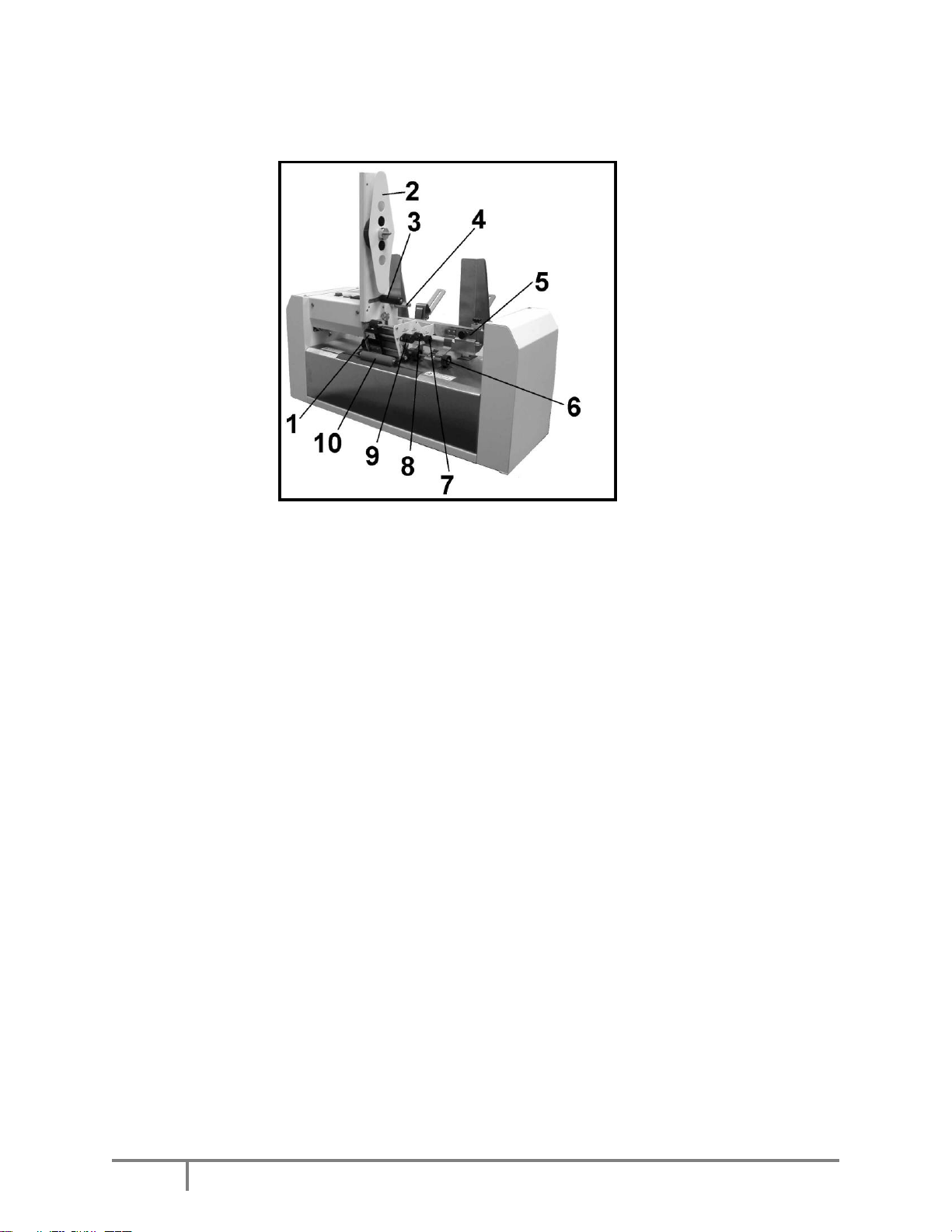
Front View
1.
Tab Sensor and Tab Guide Assembly – This assembly keeps the tab aligned so
that the sensor can sense the tab.
2.
Tab Roll Side Guide – Holds the tab roll in place on the Tab Roll Support.
3.
Reel Brake Assembly – Prevents the roll of tabs from unwinding when they are
not being fed.
4.
Tab Take-up Reel – Winds up the tab backing material.
You will need to clear the backing from this reel when it reaches a diameter of about 3”.
5.
Metering Bracket Assembly – Separates the media so that only one piece feeds
at a time
6.
Media Pressure Rollers – Drive the media through the tabber.
7.
Tab Position Adjustment Knob – Adjusts the fold position of the tab on the
media.
8.
Tab Drive Pressure Knob – Provides pressure on the tab stock to hold it against
the tab advance roller.
9.
Tab Advance Knob – Attached to the tab advance roller. Turn this roller to
manually advance the tab stock.
10.
Exit Roller – Applies pressure to the tab to help it stick to the media.
MyBinding.com
5500 NE Moore Court
Hillsboro, OR 97124
Toll Free: 1-800-944-4573
Local: 503-640-5920
Page 7

6
Rear View
1.
Media Support – Supports media during feeding.
2.
Media Side Guides – Helps maintain position of media in relationship to tabs.
3.
Tab Roll Support – Tab roll is mounted here.
4.
Media Counter – Resettable counter to track number of pieces fed.
5.
Tab Feed Button – Press this button to feed tabs, when the media feed switch is
also pressed.
6.
Media Feed Button – Press this button to feed media.
7.
Tab Sensitivity Adjustment Knob – Different tabs have different densities.
This adjustment compensates for different types of tabs.
8.
Main Power Switch – Controls the power to the tabber.
9.
Fuse – The main power fuse is located here.
10
Power Inlet – The power cord is plugged in here.
MyBinding.com
5500 NE Moore Court
Hillsboro, OR 97124
Toll Free: 1-800-944-4573
Local: 503-640-5920
Page 8

ASSEMBLY AND INSTALLATION
7
Section 2 – Assembly and Installation
Assembly
Follow the steps below to assemble the FD 262 Tabber prior to operation:
Step 1: Remove all the components from
the carton.
Step 2: Attach the two media support
guides using the two thumbscrews
provided. The pin on the guide fits into
the lower hole and the guide is secured
with the thumbscrew as shown.
Step 3: Install the two side guides over
the metering bracket support bar, then
tighten the thumbscrew.
Step 4: Loosen the thumbscrew. Place
the slot on the tab roll support over the
stud and slide it down until it reaches the
thumbscrew. Tighten the thumbscrew.
MyBinding.com
5500 NE Moore Court
Hillsboro, OR 97124
Toll Free: 1-800-944-4573
Local: 503-640-5920
Page 9

8
Installation
CAUTION
DO NOT USE AN ADAPTER PLUG OR EXTENSION CORD TO CONNECT
THE TABBER TO THE WALL RECEPTACLE.
DO NOT USE OUTLETS CONTROLLED BY WALL SWITCHES.
DO NOT USE AN OUTLET THAT SHARES THE SAME CIRCUIT WITH
LARGE ELECTRICAL MACHINES OR APPLIANCES.
Place the tabber on a flat surface away
from windows or heat sources and near
an electrical outlet. Plug the power cord
into the receptacle at the side of the
tabber then plug it into the wall outlet.
MyBinding.com
5500 NE Moore Court
Hillsboro, OR 97124
Toll Free: 1-800-944-4573
Local: 503-640-5920
Page 10

MAINTENANCE
9
Section 3 – Operating the Tabber
Follow these steps to set up the FD 262 Tabber to apply tabs to your media:
1: Load a roll of tabs on the tabber.
2: Set the sensitivity of the Tab Sensor.
3: Adjust the Metering Bracket Assembly to the media.
4: Adjust the Media Supports and Media Side guides to the media.
5: Test for proper media transport.
6: Test/Adjust for proper horizontal Tab position.
7: Adjust Tab Fold Position.
Loading Tabs:
1. Remove the Exit Roller
2. Remove the Tab Roll Side Guide
by pulling it away from the Tab
Roll Support.
3. Mount the roll of tabs with the tab
leader coming off the roll on the
exit side of the tabber.
4. Replace the Tab Roll Side Guide.
5. Unwind approximately 12 inches
of tabs and remove the first 12
tabs from the backing material.
6. Thread the tab roll leader behind
the Reel Brake Roller then in
front of the Idler Roller.
7. Set the Tab Pressure Knob to the
ON position (pressure engaged).
8. While turning the Tab Advance
Knob counter-clockwise; thread
the tab stock leader above the metal lip, up into and between the Abrasive Roller
and the Pressure Roller.
9. Continue turning the Tab Advance Knob counter-clockwise until you have
enough tab stock leader to feed 2” to 3” through the center of the Tab Take-up
Reel pins.
Operating Tip: You will need to clear the backing from the Take-up Reel when it
reaches a diameter of about 3”.
Page 11

MAINTENANCE
10
10. Slide the tabs stock into the open side of the black plastic Tab Guide and Sensor
Assembly.
Tip: Turning the Tab Pressure Knob to OFF helps with the alignment. Return
the pressure knob to the ON position after positioning.
11. Set the Tab Side Guide (post) to
confine, but not bind the tab
backing.
12. When using 1.25” wide or
narrower tab stock; adjust (slide)
the black plastic Tab Guide and
Sensor Assembly so that the red
centerline is in the approximate
center of the tab stock.
When running tabs larger than
1.25”, adjust (slide) the black
plastic Tab Guide and Sensor
Assembly so the inside of the
assembly just begins to touch the
left side of the tab stock; without
pushing the stock toward the
right. In this case, the red center line will not be centered on the tab stock.
13. Replace the Exit Roller by pushing it back into its holder.
Note: This roller is removed in the next step (Tab Sensitivity Adjustment), so you
can leave it off, if you plan to do this adjustment.
Tab Sensitivity Adjustment
There are two types of tabs designed for
use in the FD 262 Tabber. Type 1 is a
paper tab with a plain paper backing.
Type 2 is a clear plastic or translucent
paper tab with a black or brown backing
behind the tab and a white stripe between
the tabs. Do Not use clear tabs that have
a white backing behind the tab and a
black line between the tabs.
1. Remove the exit roller.
2. With the tab exposed under the sensor, turn the main power switch ON.
MyBinding.com
5500 NE Moore Court
Hillsboro, OR 97124
Toll Free: 1-800-944-4573
Local: 503-640-5920
Page 12

MAINTENANCE
11
3. Turn the Tab Sensitivity Adjustment knob fully counter-clockwise. Then turn it
clockwise until the Red LED above the adjusting knob is illuminated. Make a
note of the number that the indicator, on the knob, is pointing at.
4. Turn the Tab Drive Pressure Knob OFF and roll the tabs backwards until the Red
LED goes OFF. Turn the Tab Sensitivity Knob clockwise until the Red LED
lights again. Make a note of the number that the indicator, on the knob, is
pointing at.
NOTE: If during this step the Tab Sensitivity Knob is maxed-out (fully
clockwise), but the LED still does not light; then proceed as if the second number
is 12. If at any time during the tabbing process double tabbing occurs, advance
the setting one more position clockwise.
5. Set the Tab Sensitivity Knob indicator halfway between the two points measured
in the two previous steps.
Example: If the LED illuminates at position 4 with the tab under the sensor and at
position 10 with the backing or white line under the sensor. The difference
between the two positions is six clicks (10 - 4 = 6).
Divide this number in half (6 ÷ 2 = 3).
In this case, you turn the Tab Sensitivity Knob counter-clockwise 3 clicks, to
position 7, which is halfway between 3 and 10.
6. Turn the Tab Pressure Roller ON and use the Tab Advance Knob to advance the
tab until it starts to peel away from the backing paper.
7. Reinstall the Exit Roller.
Metering Bracket/Separator Adjustment
This procedure is used to ensure that only one piece of media is fed at a time.
1. Loosen the two thumbscrews that attach the Metering Bracket to its mounting bar.
2. Raise the Metering Bracket and place a piece of media under the separator
fingers, then lower the Metering Bracket until it contacts the media. Make sure
the media is between all the fingers and rollers.
3. Tighten the two thumbscrews.
4. Remove the media and be sure the bar is level and that the separator fingers are
not rubbing against the feed rollers.
MyBinding.com
5500 NE Moore Court
Hillsboro, OR 97124
Toll Free: 1-800-944-4573
Local: 503-640-5920
Page 13

MAINTENANCE
12
Feeding
Doubles
Reduce the distance between the separator fingers and the feed roller.
Not Feeding
Increase the distance between the media side guides and the media.
Increase the distance between the separator fingers and the feed
roller.
Heavy
Material
When setting the metering bracket, place 1-1/2 times the material
between the separator fingers and the feed roller.
Skewing
Place the media side guides closer to the edges of the media.
Check/adjust the metering bracket.
Media Supports and Media Side Guide Adjustment
1. Position the media on the Media
Supports approximately where
you wish to position the tab.
2. Place one sheet of media on the
Media Supports so that it is
resting against the Separator
Fingers.
3. Reposition the Media Supports
and Stack Rests as required to
support the media.
4. Position the Side Guides so that
they are approximately 1/16”
from each side of the media.
Media Transport Test
Take the time to verify proper media transport before trying to tab. If the media
doesn’t feed correctly, it will not be tabbed correctly.
Proper Media Transport:
One piece of media is fed at a time.
A small gap of at least 0.25” is generated between each piece of media.
Media is feeding straight.
1. Start by placing one piece of media into the hopper, so it is against or just feeding
under the separators.
2. Place a handful of media on top of the piece already in the hopper.
NOTE: When placing material on the Media Support ensure that it is shingled.
3. Be sure the Tab Switch is OFF (not illuminated), then press the Feed button to
start feeding.
If you have a problem feeding, check the following:
4. Once the media is feeding correctly, go to the next step.
Page 14

MAINTENANCE
13
Horizontal Tab Positioning
1. With media loaded, press the TAB switch (button will illuminate), followed by
the FEED switch (button will illuminate) and tabber will begin to feed.
2. Run at least two pieces, then press the Feed button to stop the tabber.
3. Check the horizontal position (leading edge, left/right position) of the tab.
4. Adjust if necessary by moving the Media Side Guides to the left or right.
5. Once the horizontal tab position is correct, perform the Tab Fold Position
Adjustment.
Tab Fold Position Adjustment
Tab a few pieces and check the position of the tab on the media. The tab should be
positioned so that approximately half of the tab folds on the top of the media and half of
the tab folds on the bottom of the media.
If placement is incorrect, follow this procedure:
1. Loosen the Tab Fold Position
Adjustment Knob.
2. Move the knob towards “TOP” to
allow more tab to be placed on the
top of the media.
Move the knob towards
“BOTTOM” to allow more of the
tab to be placed on the bottom of
the media. Tighten the knob.
3. Run at least two pieces through the machine then recheck the tab fold position,
top-to-bottom, on the second piece.
4. Repeat steps 1-3 until you are satisfied with the fold position of the tab.
Operating Sequence
1. Turn on the Main Power Switch.
2. If you want to zero out the Media Counter, press the reset button on the Media
Counter, which is located on the top of the Tabber.
3. Activate the Tab button (will illuminate)
4. Press the Feed button (will illuminate) to start the media feeding.
5. To Stop the Tabber press the Feed button again.
MyBinding.com
5500 NE Moore Court
Hillsboro, OR 97124
Toll Free: 1-800-944-4573
Local: 503-640-5920
Page 15

14
Problem
Possible Cause
Tab fold placement inconsistent
Tabs not threaded correctly.
Tabs not centered on sensor guide’s center
line.
Tab Roll is loose on spindle.
Rollers dirty, glazed or worn.
Media is feeding skewed.
Horizontal placement of tab moves
side to side
Media is feeding skewed.
Media Side Guides are loose.
Tab stock moving. Tab Side Guide post/Tab
Guide not set properly.
Multiple tabs placed on media
Tabs not centered on sensor guide’s center
line.
Tab sensitivity adjustment incorrect.
Tab sensor may be dirty or damaged.
Media feeds without tabs
Tab Switch not turned ON.
Out of Tabs.
Tab sensitivity adjustment incorrect.
Tab Drive Pressure knob in OFF position.
Media Sensor dirty/damaged.
Tabs not peeling off backing.
Media positioned incorrectly; missing Media
Sensor.
Tab sensitivity LED does not
illuminate
Power not on.
Perform tab sensitivity adjustment.
Incompatible tabs being used.
Tab sensor may be dirty or damaged.
Power Switch not illuminated
Unit not plugged in.
Switch not turned on.
Fuse blown.
Tabs stream feed
Tab Drive Pressure knob in OFF position.
Tab Sensor Switch not set properly. (Sensor
not reading tabs.)
Tabs not threaded properly. Missing sensor.
Incompatible tabs being used.
Tab sensor may be dirty or damaged.
Section 4 – Troubleshooting
Tabbing Problems:
MAINTENANCE
Page 16

15
Media Feeding Problems:
Problem
Possible Cause
Feeding Doubles
Media not properly fanned before loading.
Nested Media.
Reduce the distance between the separator
fingers and the feed roller.
Separator Fingers worn.
Media Not Feeding
Media not properly fanned before loading.
Side Guides too tight
Increase the distance between the separator
fingers and the feed roller.
Glazed or dirty feed rollers.
Feed Rollers worn.
Media Opening as it Feeds
Too much friction at the separation point.
Increase the distance between the separator
fingers and the feed roller by using 1-1/2
times the material thickness to set the
Metering Bracket.
Skewing
Media Side Guides too loose.
Metering Bracket/Separators not set evenly.
Separator Fingers or Feed Rollers worn.
MAINTENANCE
MyBinding.com
5500 NE Moore Court
Hillsboro, OR 97124
Toll Free: 1-800-944-4573
Local: 503-640-5920
Page 17

MAINTENANCE
16
WARNING
BEFORE PERFORMING ANY MAINTENANCE, DISCONNECT THE
TABBER FROM ITS POWER SOURCE!
CAUTION
NEVER SPRAY OR POUR CLEANERS DIRECTLY ON OR INTO
THE TABBER. EXCESS LIQUID COULD HARM ELECTRONIC
PARTS. ALWAYS DAMPEN A RAG WITH THE CLEANER AND
APPLY IT TO THE PARTS TO BE CLEANED.
WARNING
DO NOT USE SOLVENTS TO CLEAN THE RUBBER ROLLERS
Section 5 – Maintenance
This section describes maintenance that an experienced operator can perform. If service or
maintenance is needed, beyond what is described in this document, please contact your local
Formax dealer to obtain service and support for your tabber.
Service should only be performed by a qualified service technician.
Cleaning
The Tabber must be cleaned regularly of accumulated paper dust and ink. Unplug the tabber
from the wall outlet before cleaning.
The visible areas are best cleaned with a vacuum that has a soft brush attachment to help loosen
the dust particles.
The covers of the machine may be cleaned with any standard household cleaner, which is nonabrasive and does not contain plastic harming solvents.
Feed Rollers and Forwarding Rollers
The feed and forwarding rollers can become glazed with paper lint and ink from the media. They
should be regularly cleaned with a mild abrasive household cleaner on a damp cloth.
Avoid using solvents on the rubber rollers.
MyBinding.com
5500 NE Moore Court
Hillsboro, OR 97124
Toll Free: 1-800-944-4573
Local: 503-640-5920
Page 18

MAINTENANCE
17
WARNING
DO NOT USE ABRASIVES OF ANY KIND TO CLEAN SENSORS.
DO NOT USE LIQUIDS OF ANY KIND, TO CLEAN SENSORS.
Cleaning the Sensors
Periodically check the tab sensor located in the Tab Sensor and Guide assembly. The sensor
should be clean and free of accumulated paper dust. Use a vacuum with a soft brush attachment
or dry compressed air to remove the dust.
To aid in cleaning, the Tab Guide Assembly can be removed from the shaft by pulling out on the
Tab Guide Assembly.
WARNING! Be careful not to damage the Tab Guide Assembly or sensor wiring when
removing/installing this assembly. If you don’t feel comfortable performing this procedure,
please contact a qualified Formax service technician to perform this procedure for you.
Also, clean the media sensor located in the plate attached to the Tab Fold Position Adjustment
Knob. Use a vacuum with a soft brush attachment or dry compressed air to remove the dust.
MyBinding.com
5500 NE Moore Court
Hillsboro, OR 97124
Toll Free: 1-800-944-4573
Local: 503-640-5920
Page 19

18
Appendix - Specifications
Dimensions:
25" Wide x 15.5" Depth x 22" High
Speed:
12,000 pieces per hour (8.5" x 11" tri-folds)
Weight:
45 lbs. Shipping wt.; 40 lbs. installed
Media Size:
Length – 3 5/8" to 18"
Width – 5" to 17"
Media Thickness:
Up to 5/32"
Tab Size:
Length – 5/8" min to 1.5" max
Width – 5/8” min to 1.5” max
Tab Sensitivity Control:
Adjusts for density in tab/wafer seals
Reel Capacity:
10,000 tabs
Counter:
5 digit LCD (operator resettable)
Feeder:
Top load, bottom feed for continuous operation
Electrical:
120 VAC 50/60 Hz
Options:
CJ-10 Drop-Stacking Conveyor
FD 262 Tabber
INDEX
Specifications subject to change without notice.
MyBinding.com
5500 NE Moore Court
Hillsboro, OR 97124
Toll Free: 1-800-944-4573
Local: 503-640-5920
Page 20

Appendix B – Obtaining Supplies, Service and
Part #
Description
Roll
Diameter
Tabs per
Roll
Rolls per
Case
262-10
1" Round White Paper Tabs
9”
10K
12
262-11
1" Round Translucent Tabs
9”
11K
12
262-13
1.5" Tabs White Paper, No Perforation
9”
7K
8
262-14
1.5" Tabs Translucent, No Perforation
9”
7K
8
Clear or Translucent tab stock with black
box below tab area
Tab Material: Clear or Translucent
Backing: Black block below tab area.
Tab Material: White Paper Circle
Backing: All White (plain)
Support
Please contact your local Formax dealer to obtain supplies, service and support for your tabber.
Service should only be performed by a qualified service technician.
FD 262 Tab Supplies:
The following supply items are available from Formax and your Formax dealer. Please check
with your Formax dealer for possible changes or additions to the following tab supplies.
All the tab rolls, shown above, are on a 3” core.
Examples of Compatible Tab Stocks:
MyBinding.com
5500 NE Moore Court
Hillsboro, OR 97124
Toll Free: 1-800-944-4573
Local: 503-640-5920
 Loading...