

Page 1

Forma Scientific, Inc.
Millcreek Road, P.O. Box 649
Marietta, Ohio 45750
U.S.A.
Telephone: (740) 373-4763
Telefax: (740) 373-4189
________________________________________
Models:
707, 771, 733 and 754
Non-CFC, Ultra-Low Temperature
Chest Freezers
3.0 and 6.7 cu. ft. capacity
Manual No. 7000707 Rev. 3
Read this Instruction Manual
Failure to read, understand and follow the instructions in this manual may result in
damage to the unit, injury to operating personnel and poor equipment performance.
CAUTION: All internal adjustments and maintenance must be performed
by qualified service personnel.
Refer to the serial tag on the
back cover of this manual
Page 2
Forma Model 700 Series ____________________________________________________
*Refer to listing of all model numbers on page ii.
*700 Series Freezers
707 6.7 cu ft 120V
771 6.7 cu ft 230V
733 3.0 cu ft 120V
754 3.0 cu ft 230V
The material in this manual is for information purposes only. The contents and the product it
describes are subject to change without notice. Forma Scientific, Inc. makes no representations or
warranties with respect to this manual. In no event shall Forma Scientific, Inc. be held liable for any
damages, direct or incidental, arising out of or related to the use of this manual.
MANUAL NO. 7000707
3 19279/FR-1402 6/21/00 Revised electrical schematics aks
2 FR-1357 12/1/99 Updated per A. Thomas for IEC 1010 (CE listing) ccs
-- 18249/SI-7545 7/7/99 Added P/N 195518 & 195519 air filter kits to parts list ccp
1 18286/FR-1296 5/11/99 Updated schematics for 771/5477 ccp
-- -- 11/17/98 Added battery change note to Section 3.6 deg
--- FR-1223 6/8/98 Changed temp board heg
-- FR-1203 5/26/98 Added metric units to ref. drawing for IEC-1010
0 2/98 Original Manual deg
REV ECR/ECN DATE DESCRIPTION By
ii
Page 3
Forma Model 700 Series ______________________________________________Service
Do You Need Information or Assistance on Forma
Products?
do, please contact us 8:00 a.m. to 7:00 p.m. (Eastern Time) at:
If you
1-740-373-4763Direct
1-888-213-1790Toll Free, U.S. and Canada
1-740-373-4189FAX
http://www.forma.comInternet Worldwide Web Home Page
[email protected] E-Mail Address
Our staff can provide information on pricing and giveyou quotations. We
Sales Support
can take your order and provide delivery information on major equipment items or make
arrangements to have your local sales representative contact you. Our products are listed on the
Internet and we can be contacted through our Internet home page.
Ourstaff can supply technical information about proper setup,
Service Support
operation or troubleshooting of your equipment. We can fill your needs for spare or replacement
parts or provide you with on-site service. We can also provide you with a quotation on our
Extended Warranty for your Forma products.
Whatever Forma products you need or use, we will be happy to discuss your
applications. If you are experiencing technical problems, working together, we will help you
locate the problem and, chances are, correct it yourself...over the telephone without a service
call.
When more extensive service is necessary, we will assist you with direct factory trained
technicians or a qualified service organization for on-the-spot repair. If your service need is
covered by the warranty, we will arrange for the unit to be repaired at our expense and to your
satisfaction.
Regardless of your needs, our professional telephone technicians are available to assist
you Monday through Friday from 8:00 a.m. to 7:00 p.m. Eastern Time. Please contact us by
telephone or fax. If you wish to write, our mailing address is:
ThermoQuest
Forma Scientific Division
Millcreek Road, PO Box 649
Marietta, OH 45750
International customers please contact your local ThermoQuest, Forma Scientific
Division distributor.
iv
Page 4
Forma Model 700 Series _______________________________________________Safety
General Safety Notes used in this Manual
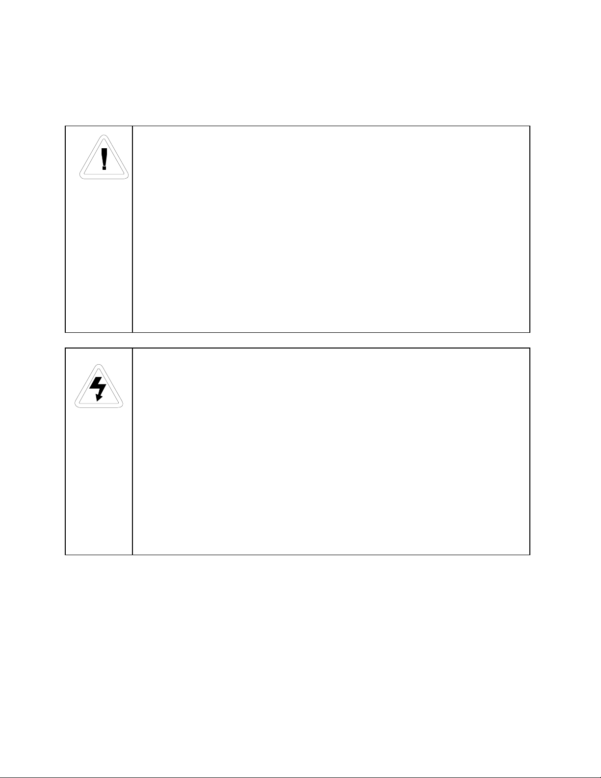
Important operating and/or maintenance instructions. Read the accompanying text
carefully.
Ce symbole attire l’attention de l’utilisateur sur des instructions importantes de
fonctionnement et/ou d’entretien. Il peut être utilisé seul ou avec d’autres symboles de
sécurité. Lire attentivement le texte d’accompagnement.
Wichtige Betriebs- und/oder Wartungshinweise. Lesen Sie den nachfolgenden Text
sorgfältig.
Importante instruccions de operacion y/o mantenimiento. Lea el texto acompanante
cuidadosamente.
Potential electrical hazards. Only qualified persons should perform procedures
associated with this symbol.
Ce symbole attire l’attention de l’utilisateur sur des risques électriques potentiels.
Seules des personnes qualifiées doivent appliquer les instructions et les procédures
associées à ce symbole.
Gefahr von Stromschlägen. Nur qualifizierte Personen sollten die Tätigkeiten
ausführen, die mit diesem Symbol bezeichnet sind.
Potencial de riesgos electricos. Solo personas das capacitadadas deben ejecutar los
procedimientos asociadas con este simbulo.
v
Page 5
Forma Model 700 Series _______________________________________________Safety
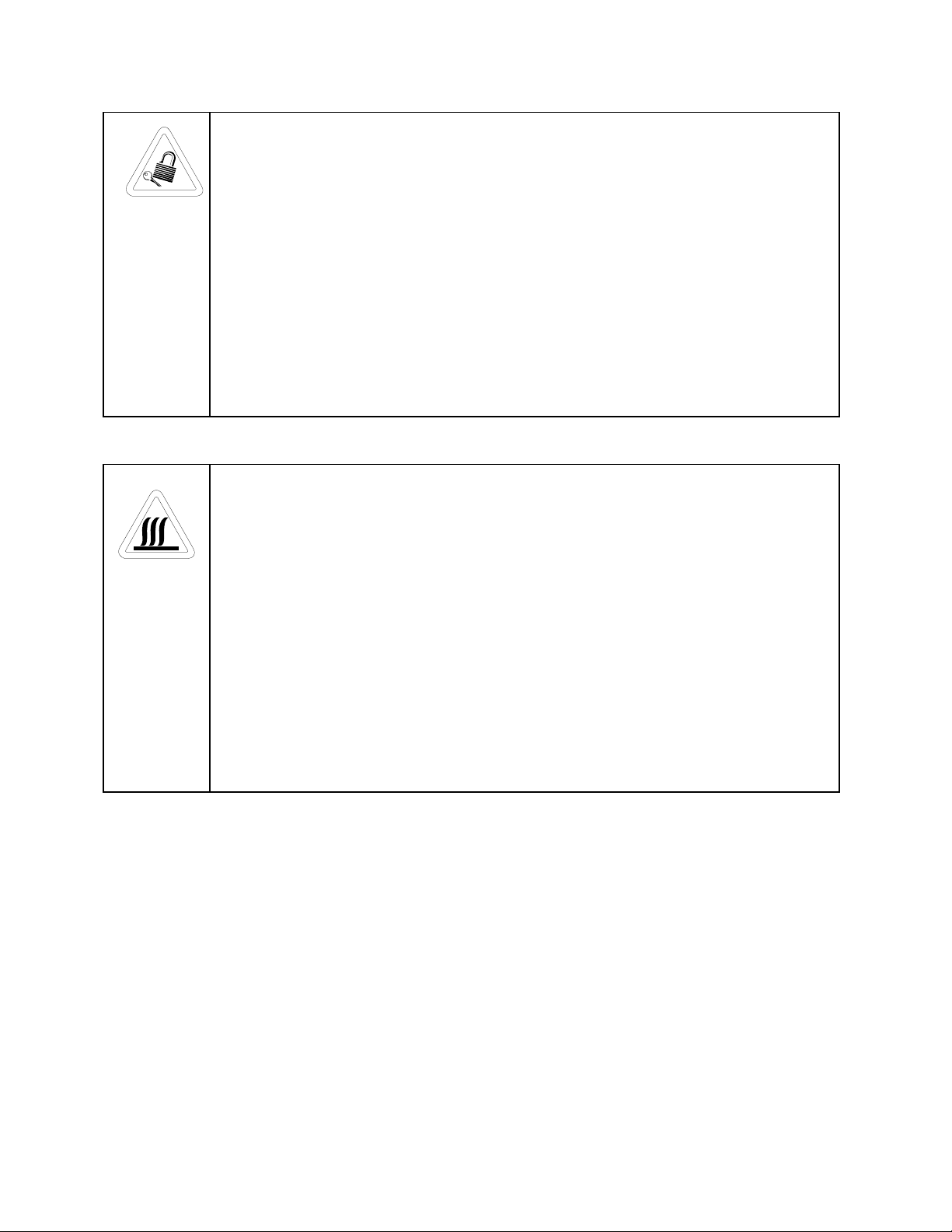
Equipment being maintained or serviced must be turned off and locked off to prevent
possible injury.
Risques potentiels liés à l’énergie. L’équipement en entretien ou en maintenance doit
être éteint et mis sous clé pour éviter des blessures possibles.
Geräte, an denen Wartungs- oder Servicearbeiten durchgeführt werden, müssen
abgeschaltet und abgeschlossen werden, um Verletzungen zu vermeiden.
El equipo recibiendo servicio o mantenimiento debe ser apagado y segurado para
prevenir danos.
Hot surface(s) present which may cause burns to unprotected skin or to materials
which may be damaged by elevated temperatures
Présence de surface(s) chaude(s) pouvant causer des brûlures sur la peau non
protégée, ou sur des matières pouvant être endommagées par des températures
élevées.
Heiße Oberfläche(n) können ungeschützter Haut Verbrennungen zufügen oder
Schäden an Materialien verursachen, die nicht hitzebeständig sind.
Superficias calientes que pueden causar quemaduras a piel sin proteccion o a
materiales que pueden estar danados por elevadas temperaturas.
√√ Always use the proper protective equipment (clothing, gloves, goggles etc.).
√√ Always dissipate extreme cold or heat and wear protective clothing.
√√ Always follow good hygiene practices.
√√ Each individual is responsible for his or her own safety.
vi
Page 6

Forma Model 700 Series _____________________________________________Contents
Table of Contents
Section 1 - Installation and Start-Up
1.1 Unloading and Moving the Freezer.......................................................1-1
1.2 Getting to Know Your Freezer .............................................................1-2
1.3 Environmental Conditions....................................................................1-5
1.4 Installing the Wall Bumpers.................................................................1-5
1.5 Location ...............................................................................................1-6
1.6 Connecting the Alarm Battery..............................................................1-6
1.7 Remote Alarm Contacts........................................................................1-7
1.8 Optional Recorder ................................................................................1-7
a. Connecting recorder battery...........................................................1-7
b. Installing the chart paper...............................................................1-7
1.9 Attaching the Power Cord ....................................................................1-8
1.10 Power Switch (mains disconnect).......................................................1-8
1.11 Electrical Requirements and Connection .............................................1-9
1.12 Factory Settings...................................................................................1-9
1.13 Start Up and Loading...........................................................................1-9
Section 2 - Operation
2.1 Changing the Control Temperature Set Point........................................2-1
2.2 Changing the Over Temperature Alarm Set Point.................................2-1
2.3 Alarms..................................................................................................2-2
2.4 Silencing the Over Temperature Alarm ................................................2-3
Section 3 - Calibration
3.1 Temperature Display Calibration..........................................................3-1
3.2 Optional Recorder Calibration ..............................................................3-2
a. Changing the recorder range............................................................3-2
b. Calibrating the chart recorder..........................................................3-3
vii
Page 7

Forma Model 700 Series _____________________________________________Contents
Section 4 - Routine Maintenance
4.1 Cleaning the Cabinet Exterior ..............................................................4-1
4.2 Cleaning the Air Filter..........................................................................4-1
4.3 Cleaning the Condenser ........................................................................4-1
4.4 Defrosting the Chamber........................................................................4-2
4.5 Cleaning the Lid Gasket .......................................................................4-2
4.6 Replacing the Battery............................................................................4-3
4.7 Preparing the Unit for Storage...............................................................4-3
Section 5 - Service
5.1 Servicing the Refrigeration System ......................................................5-1
Section 6 - Specifications
Section 7 - Parts List
Section 8 - Refrigeration Drawings
Section 9 - Electrical Schematics
Section 10 - Warranty Information
viii
Page 8
Forma Model 700 Series ___________________________________Installation/Start-Up
Section 1 - Installation and Start-Up
1.1 Unloading and Moving the Freezer
To remove the freezer from the pallet, use the 7/16” wrench to remove all the bolts
securing the shipping bracket to the pallet. Remove the shipping bracket. Remove the ramp
boards from the pallet and place the slotted end over the ramp brackets on the pallet. The support
blocks on the ramps will be facing down. Before moving the freezer, make sure the casters are
unlocked and moving freely. Align the caster with the ramp boards. Use adequate personnel to
roll the freezer off the pallet.
If tipped more than 45°, allow the unit to set upright for
24 hours before start up.
The freezer can be easily pushed to the desired approved location that is described in
Section 1.5. When the freezer is in position, set the front caster brakes.
The freezer must not be moved with the product load inside.
1-1
Page 9
Forma Model 700 Series____________________________________Installation/Start-Up
1.2 Getting to Know Your Freezer
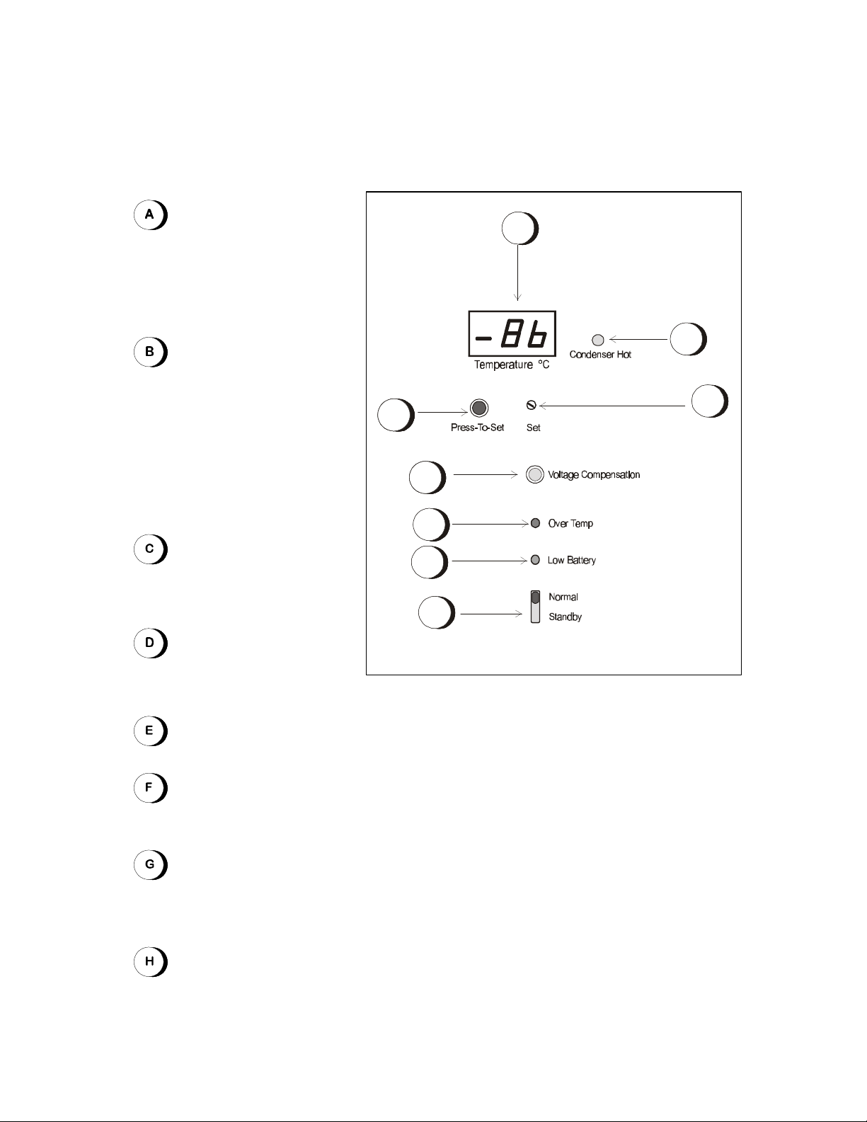
LED display - Shows
actual chamber temperature
and indicates the control
temperature set point when the
Press-To-Set button is pressed.
Condenser Hot
indicator - Lights when the
thermostat on the condenser
reaches 40°C, indicating
typically a dirty air filter, a
clogged condenser, a fan
failure or high ambient
temperature.
Set Point Adjustment
Screw - Sets the control
temperature set point.
AA
B
C
H
G
F
E
D
Normal/Standby
switch - Silences the audible alarm.
Figure 1-1, Control Panel
Low Battery indicator - Flashes when the battery needs to be replaced.
Over Temp indicator - Flashes when the chamber temperature rises above the
Over Temperature Alarm setting.
Voltage Compensation indicator - Indicates when the in-coming electrical
power is being automatically adjusted to ensure that the compressor operates within
specification.
Press-to-Set button - Press to display control temperature set point.
1-2
Page 10
Forma Model 700 Series____________________________________Installation/Start-Up
3
3
1 2
1 2
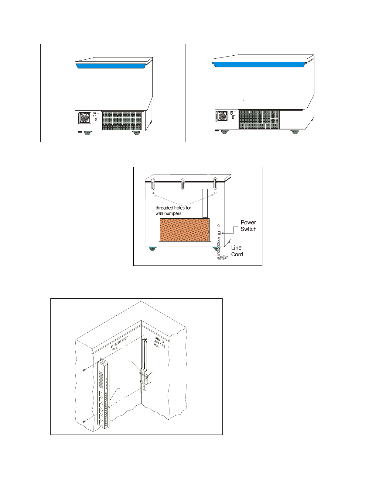
Figure 1-2 Figure 1-3
3.0 cu. ft. Chest Freezer 6.7 cu. ft. Chest Freezer
Recorder
Probe
Probe
Cover
Figure 1-4
Chest Freezer Base, back view
Figure 1-5
Chamber Probe Assembly
Performance Alarm
Monitor and
Temperature Probe
1-3
Page 11
Forma Model 700 Series____________________________________Installation/Start-Up
1.3 Environmental Conditions
The ULT Freezers are designed to be electrically safe in the following environmental
conditions:
• Indoors
• Altitude: Up to 2,000 meters
• Temperature: 5°C to 43°C
• Humidity: 80% RH at or below 31°C, decreasing linearly to 50% RH at 40°C
• Mains Supply Fluctuations: ±10% of nominal.
• Installation Category II
• Pollution Degree 2
1
2
• Class of Equipment I
• Climatic Class T (Tropical)
1
Installation category (overvoltage category) defines the level of transient overvoltage which the
instrument is designed to withstand safely. It depends on the nature of the electricity supply and its
overvoltage protection means. For example, in CAT II which is the category used for instruments in
installations supplied from a supply comparable to public mains such as hospital and research
laboratories and most industrial laboratories, the expected transient overvoltage is 2500V for a 230V
supply and 1500V for a 120V supply.
3
2
Pollution degree describes the amount of conductive pollution present in the operating environment.
Pollution degree 2 assumes that normally only non-conductive pollution such as dust occurs with the
exception of occasional conductivity caused by condensation.
3
Class T (Tropical) means that the freezers are electrically safe in a 43°C ambient.
1.4 Installing the Wall Bumpers (Refer to Figure 1-4)
The parts bag, located inside the cabinet, contains the following parts.
Qty. Stock # Description Purpose
2 224 510016 1/4-20 x 5-1/2" Bolt Wall Bumper
2 311 380520 Neoprene Cap Cap Protector
Install the bolts into the pre-tapped holes on the back of the compressor section.
Install a neoprene cap on each bolt. Refer to Figure 1-4 for the locations of the pretapped holes.
1-4
Page 12
Forma Model 700 Series____________________________________Installation/Start-Up
1.5 Location
Locate the freezer on a firm, level surface in an area with an ambient temperature
between 18°C and 32°C. Provide ample room to reach the mains disconnect switch
(power switch) located on the rear of the freezer.
For proper ventilation and airflow, a minimum of 5" of clear space
is required around the freezer.
1.6 Connecting the Alarm Battery
NOTE: The battery must be connected upon start-up so that the alarm will activate
during an Overtemperature condition.
1. To gain access to the battery, remove the grill on the front of the freezer. The grill is
attached to the freezer by friction plugs on each of the four corners and is readily
pulled off. The battery is the rectangle fastened by Velcro to the compressor
compartment frame and has a connector with red and black wires. Another red and
black wire set with connector is secured to the wiring harness passing through the
area of the freezer. Join the two wire connectors and replace the grill.
2. When the battery is connected, the OVERTEMP light will flash and the alarm will
sound. Turn the NORMAL/STANDBY switch to the STANDBY position. This will
silence the alarm. The alarm will remain silent until the unit is below alarm
setpoint. The alarm setpoint is factory set for -65°C. If another setpoint is required,
see Section 2.2.
1-5
Page 13
Forma Model 700 Series____________________________________Installation/Start-Up
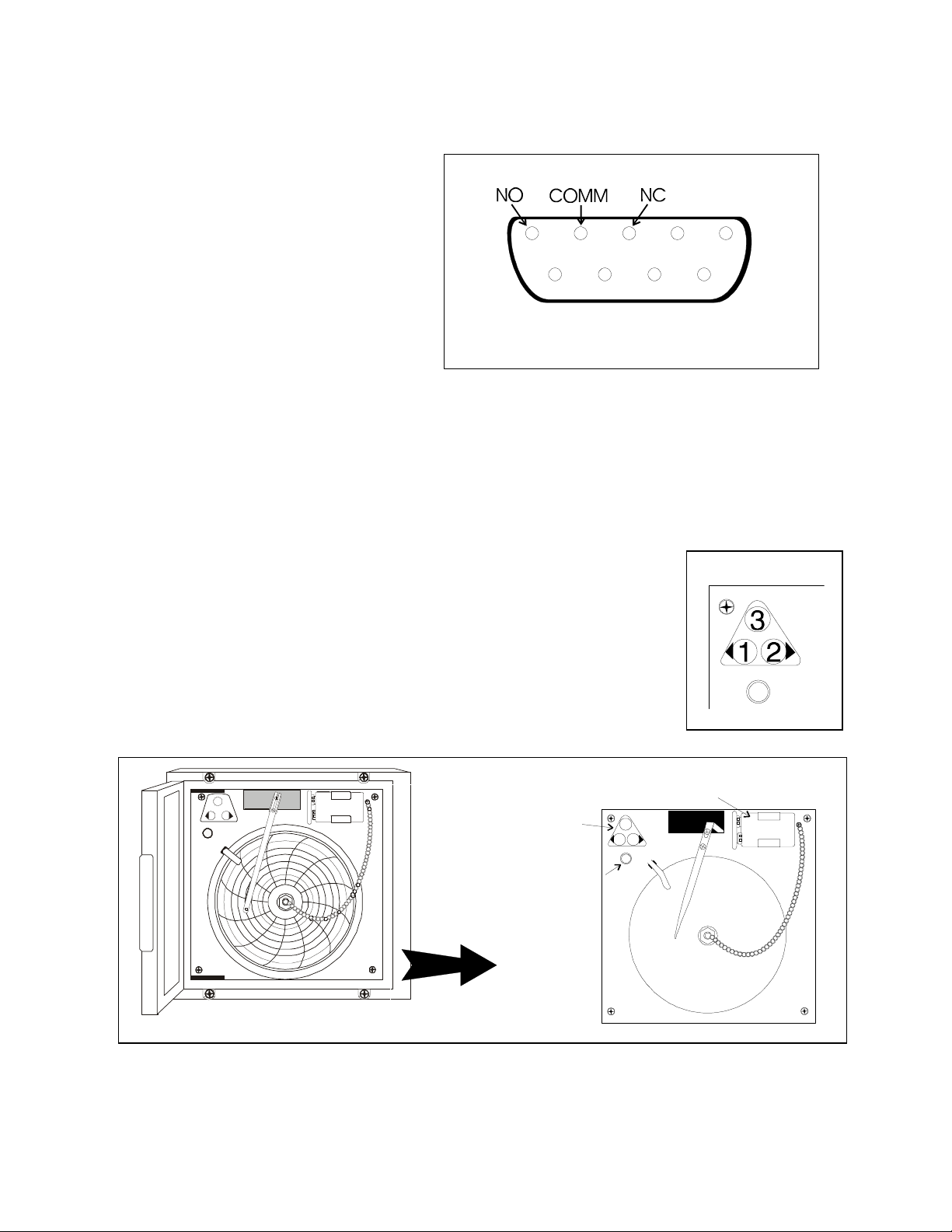
1.7 Remote Alarm Contacts
Remote alarm contacts are
located on the rear of the unit.
See Figure 1-6 for pin
description, shown in the alarm
state. The Forma part number
for the plug required is 195482.
Maximum rating for this plug
is 1.0A @ 30VAC.
Remote Alarm Contact
Figure 1-6
1.8 (Optional) Temperature Recorder
a. Connecting recorder battery
Open the glass door of the recorder and connect the 9-volt battery. The green
light on the recorder will come on.
b. Installing the chart paper
1. Open the glass door of the recorder and press button #3 until the
pen begins to move outward.
2. Unscrew the knob at the center of the chart and remove the
paper.
3. Install the new chart paper, position the paper to the correct
time line and replace the knob.
4. Remove the cap from the felt pen and press button #3.
3
1 2
Program selection and
calibration buttons
Green LED
9-volt battery
3
1 2
Figure 1-8 Chart Recorder, detail view
1-6
Page 14
Forma Model 700 Series____________________________________Installation/Start-Up
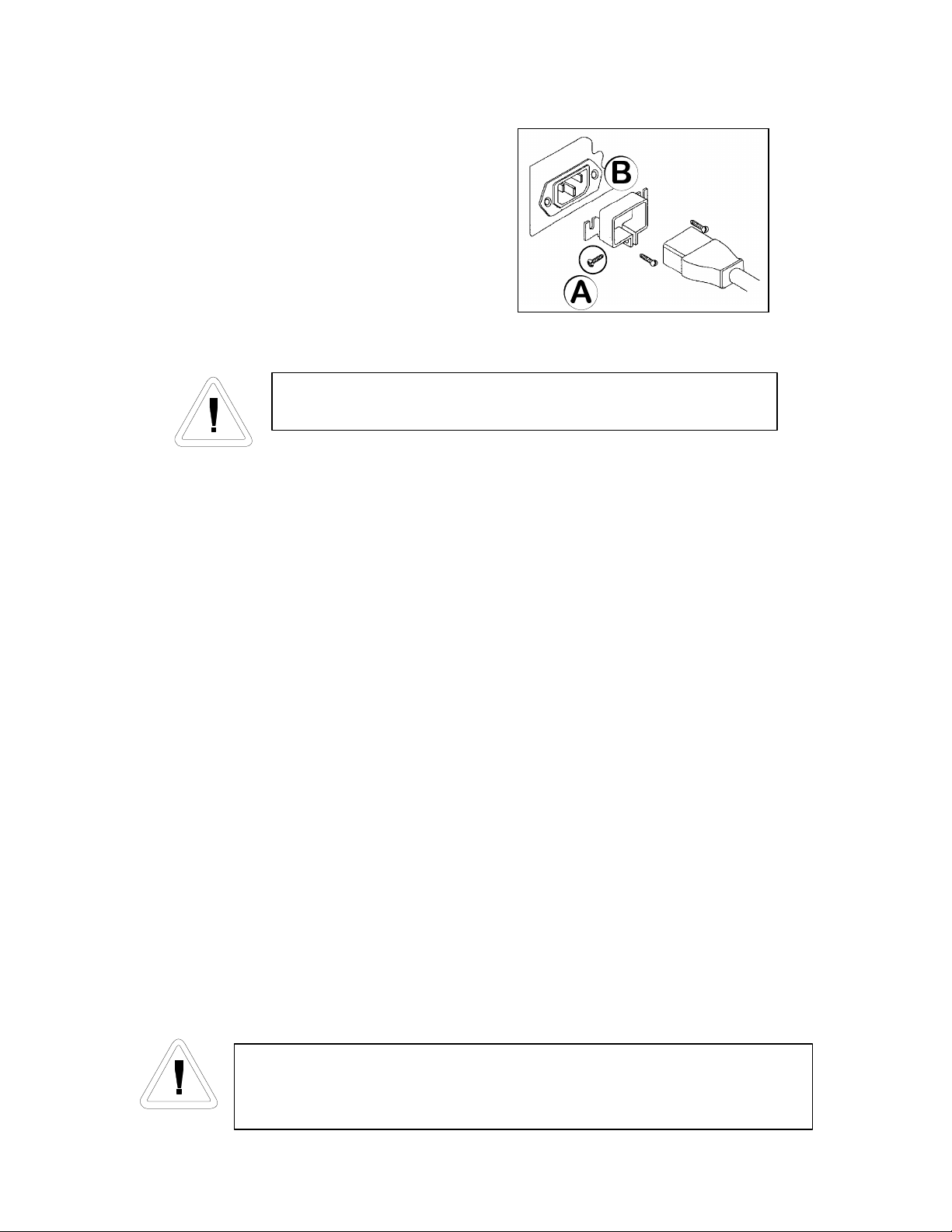
1.9 Attaching the Power Cord
1. Loosen screw (A) located on the power
cord retainer.
2. Spread the power cord retainer.
3. Insert the power cord into the power outlet
module (B).
4. Tighten screw (A) on the power cord
retainer.
Power Cord Assembly
Figure 1-9
Make sure the power cord connection is completely seated.
1.10 Power Switch (mains disconnect)
The power switch is located on the rear of the unit, directly above the power cord.
The power switch is also a circuit breaker that protects the entire unit.
1.11 Electrical Requirement and Connection
• The freezer should be operated on a dedicated grounded service.
• Check voltage rating on the serial tag of the unit and compare it with the outlet voltage.
• With the power switch turned off, plug the line cord into the wall outlet.
1.12 Factory Settings
• Control Temperature – 707 & 771: -80°C
– 733 & 754: -75°C
• Over Temperature Alarm: -65°C
If you wish to change any of these settings, see the appropriate section(s) in Section 2.
1.13 Start Up and Loading
• Turn the freezer on and allow it to run empty overnight.
• When the empty freezer has stabilized overnight at the control temperature set point, load
the chamber with pre-frozen product.
The freezer was designed for the storage of pre-frozen product
only. The addition of warm product may cause a temporary rise in
the cabinet temperature.
1-7
Page 15
Forma Model 700 Series____________________________________________Operation
Section 2 – Operation
2.1 Changing the Control Temperature Set Point
1. Remove the screwdriver on the front left corner of the control panel.
2. Press and hold in the PRESS-TO-SET key on the control panel.
3. Using the screwdriver, turn the SETscrew until the desired temperature is displayed.
Clockwise lowers the temperature and counter clockwise raises the temperature. The
approved operating temperature range for the 707 & 771 is -50°C to -86°C and the
range for the 733 & 754 is –50°C to –77°C.
The unit should NEVER be set to operate below the approved
operating range. Setting the unit below this range will cause the
compressors to operate continuously and reduce compressor life.
2.2 Changing the Over Temp Alarm Set Point
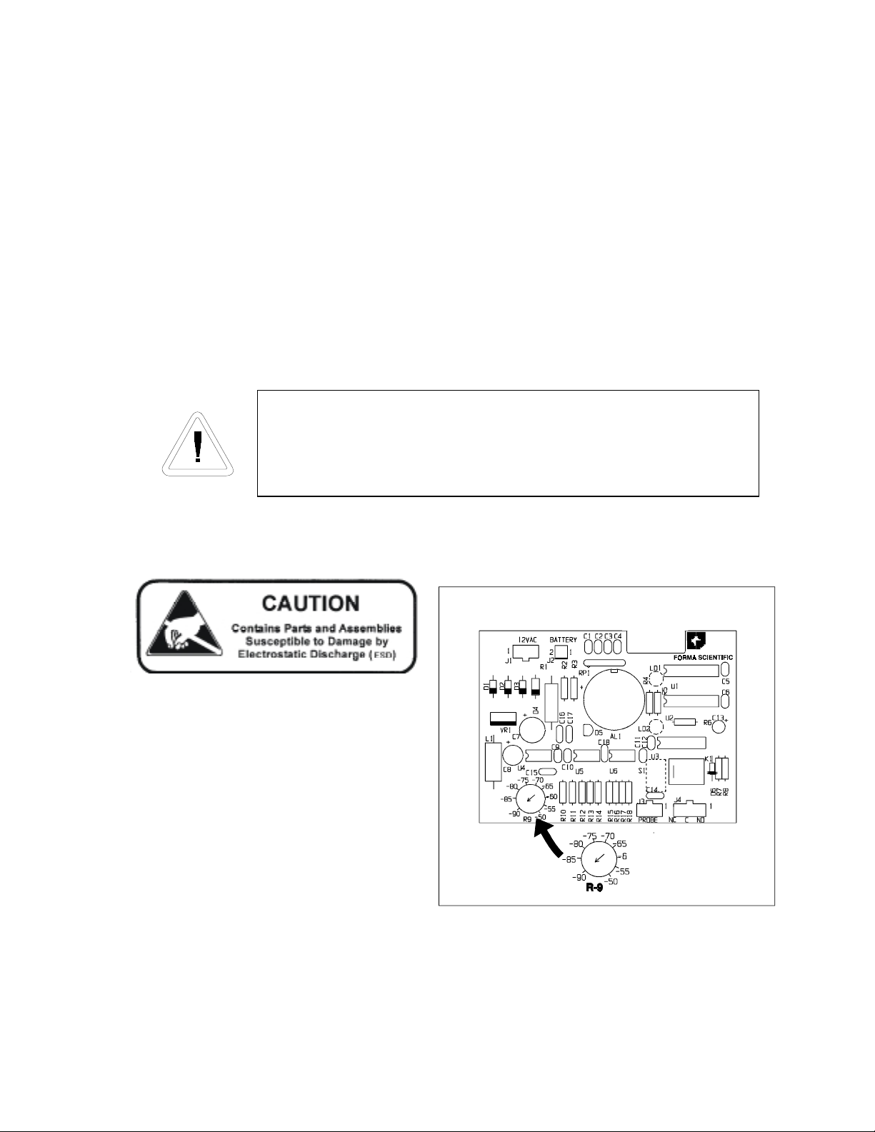
The following procedure sets the alarm for
a precise temperature during initial set up. If a
precise temperature is not required, set R9 to
the desired temperature.
1. Set the unit to operate at the desired alarm
point (see Section 2.1) and allow the unit
to operate until it reaches the set point.
2. Remove the top two screws securing the
control panel and loosen the bottom two
screws. Carefully remove the control
panel.
3. Remove the six screws securing the cover of the
box attached to the inside of the control panel to
expose the alarm board.
Figure 2-1, Temperature
Alarm Circuit Board
showing R-9 Control
4. Turn the switch on the control panel to the NORMAL position.
2-1
Page 16
Forma Model 700 Series____________________________________________Operation
5. If the unit alarms, slowly adjust R9 clockwise (warmer) until the alarm turns off. If the unit is
not in alarm, slowly adjust R9 counterclockwise (colder) until the alarm turns on.
6. The alarm is now set for the desired temperature. Reinstall the box cover and secure with
screws. Carefully install the control panel to its proper location and secure with screws.
7. Set the unit to the desired control temperature. See Section 2.1.
2.3 Alarms
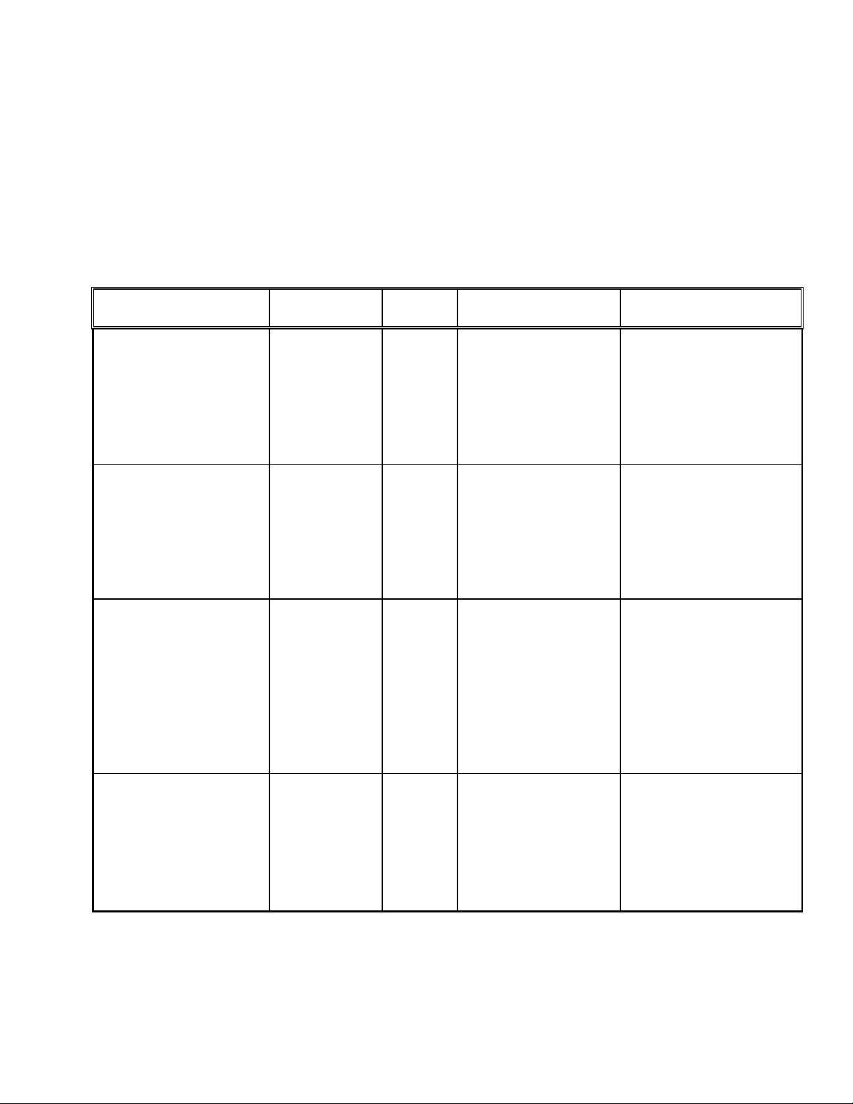
Alarm Description Visual Audible Cause Action Required
Over Temperature Flashing
(red)
Condenser Hot On (red) ---
Low Battery Flashing
(red)
On
---
• Unit is above
alarm setpoint.
• Addition of
excessive
product load
• Filter and/or
condenser dirty.
• Operating freezer
in greater than
40°C ambient.
• Rechargeable
battery not
connected
• Rechargeable
battery needs
replaced
• Check freezer
operation.
• See Section 4.2 and
4.3 for cleaning
filter and
condenser.
• See Section 1.6.
• Replace battery.
See Section 4.7 for
battery replacement
instructions. See
spare parts list for
battery part number.
Voltage
Compensation
On (green) ---
2-2
• Incoming voltage
too high or too
low
• Check if line
voltage is within
operating range. See
Section 6. If within
specs, no action is
required.
Page 17
Forma Model 700 Series____________________________________________Operation
2.4 Silencing the Over Temperature Alarm
• Move the switch from the NORMAL position to the STANDBY position. When the
alarm condition has been corrected, the alarm will sound. The switch must then be
returned to the NORMAL position to exit STANDBY mode.
If the unit is left in the STANDBY mode, none of the alarms listed will
sound, alarm lights only will turn on.
2-3
Page 18
Forma Model 700 Series ______________________________________________Calibration
Section 3 - Calibration
Calibration must be performed when the unit is at operating temperature.
Required equipment: Accurate low-temperature remote bulb thermometer or thermocouple of
known accuracy.
3.1 Temperature Display Calibration
Place a measuring device near the
probe cover. See Figure 1-5.
1. Allow the unit to stabilize at the
operating temperature.
2. Remove the top two screws securing
the control panel and loosen the
bottom screws.
3. Carefully remove the control panel.
4. Remove the six screws securing the
cover of box attached to the inside of
the control panel. Remove the cover.
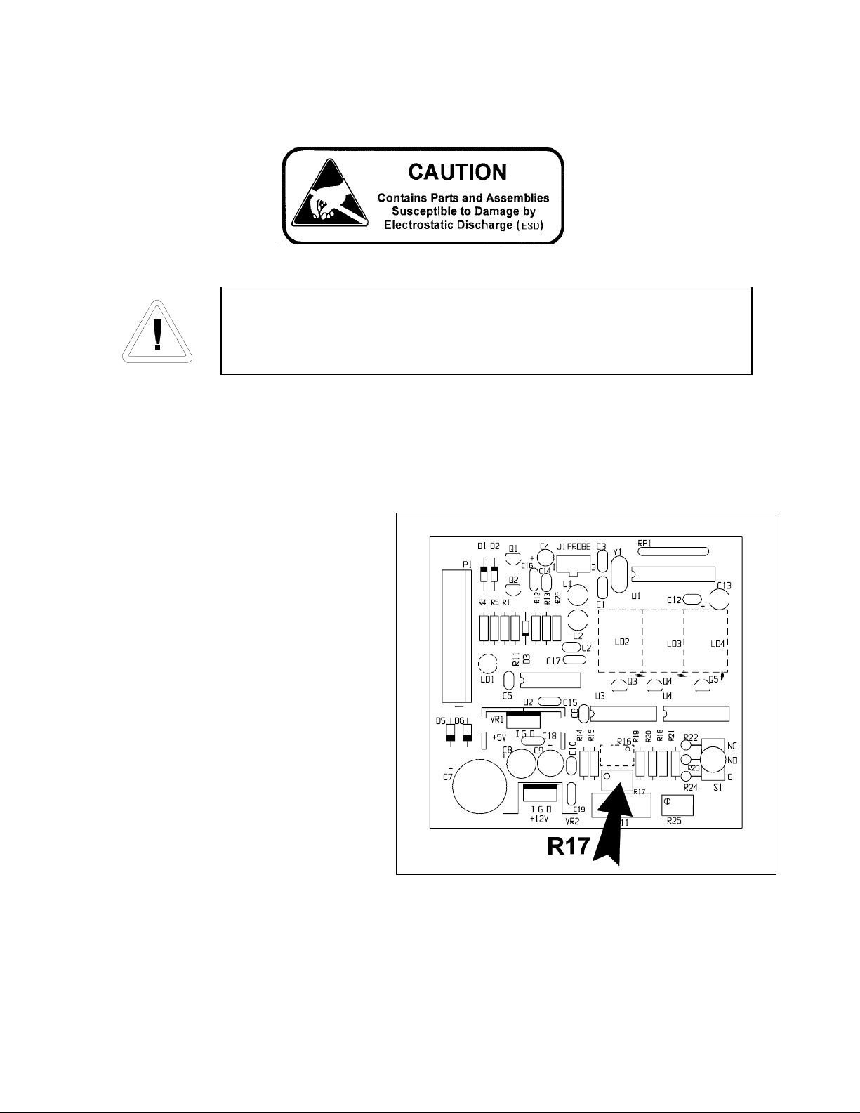
5. Adjust R17 until the control panel
display matches the independent
measuring device. Several turns of
R17 may be required to achieve the
desired temperature.
6. Reinstall cover to the box and secure.
7. Check the control temperature set point. Set
point may have been altered during the
calibration procedure.
Figure 3-1,
Temperature Control Board
showing R-17 Location
3-1
Page 19
Forma Model 700 Series ______________________________________________Calibration
3.2 Optional Recorder Calibration
a. Changing the recorder range:
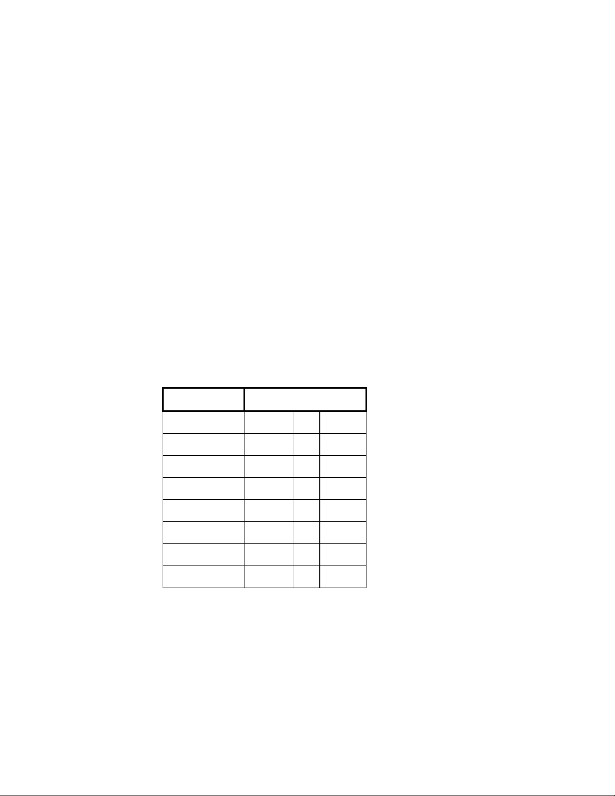
The chart recorder contains eight temperature ranges and is factory-programmed for
the freezer.
1. Press and hold button #3 for one second, then let the pen move off of the chart
paper.
2. Press and hold for five seconds either button #1 or button #2.
3. Release the button and the green LED will begin to flash. Count the number of
flashes to determine the present program setting.
4. To change the program setting, press the left or right arrows to increase or decrease
the count.
5. When the desired program number is flashing, press button #3 to bring the pen arm
back onto the chart. Recording will begin in the new program.
NOTE: Changing ranges may require an offset calibration as outlined in Section 3.2.b.
Program No. Range
Program 1 -40°C to 30°C
Program 2 0°C to 60°C
Program 3 -100°C to 38°C
Program 4 -5°C to 50°C
Program 5 0°C to 100°C
Program 6 -100°C to -200°C
Program 7 -115°C to 50°C
Program 8 -10°C to 70°C
Table 3-1
Recorder Range Chart
3-2
Page 20

Forma Model 700 Series ______________________________________________Calibration
b. Calibrating the chart recorder:
The recorder must be in service for 24 hours before performing the following
calibration procedure.
1. Place an accurate thermometer in the chamber next to the recorder probe.
2. Temperature probes for the recorder are located in the left front corner of the freezer
chamber (Figure 1-5).
3. After about three minutes, compare the thermometer reading with the chart recorder
reading.
4. If an adjustment is necessary, press the #1 button to move the pen to the left or the
#2 to move the pen to the right. The button must be held about five seconds before
the pen begins to move. Release the button when the pen position matches the
thermometer.
NOTE: The felt-tip pen on the recorder requires periodic replacement. Usually the ink
will appear to fade before replacement becomes necessary. Additional pen tips may be
purchased from Forma Scientific. Refer to Parts List, Section 7. o
3-3
Page 21
Forma Model 700 Series _____________________________________________Maintenance
Section 4 - Routine Maintenance
4.1 Cleaning The Cabinet Exterior
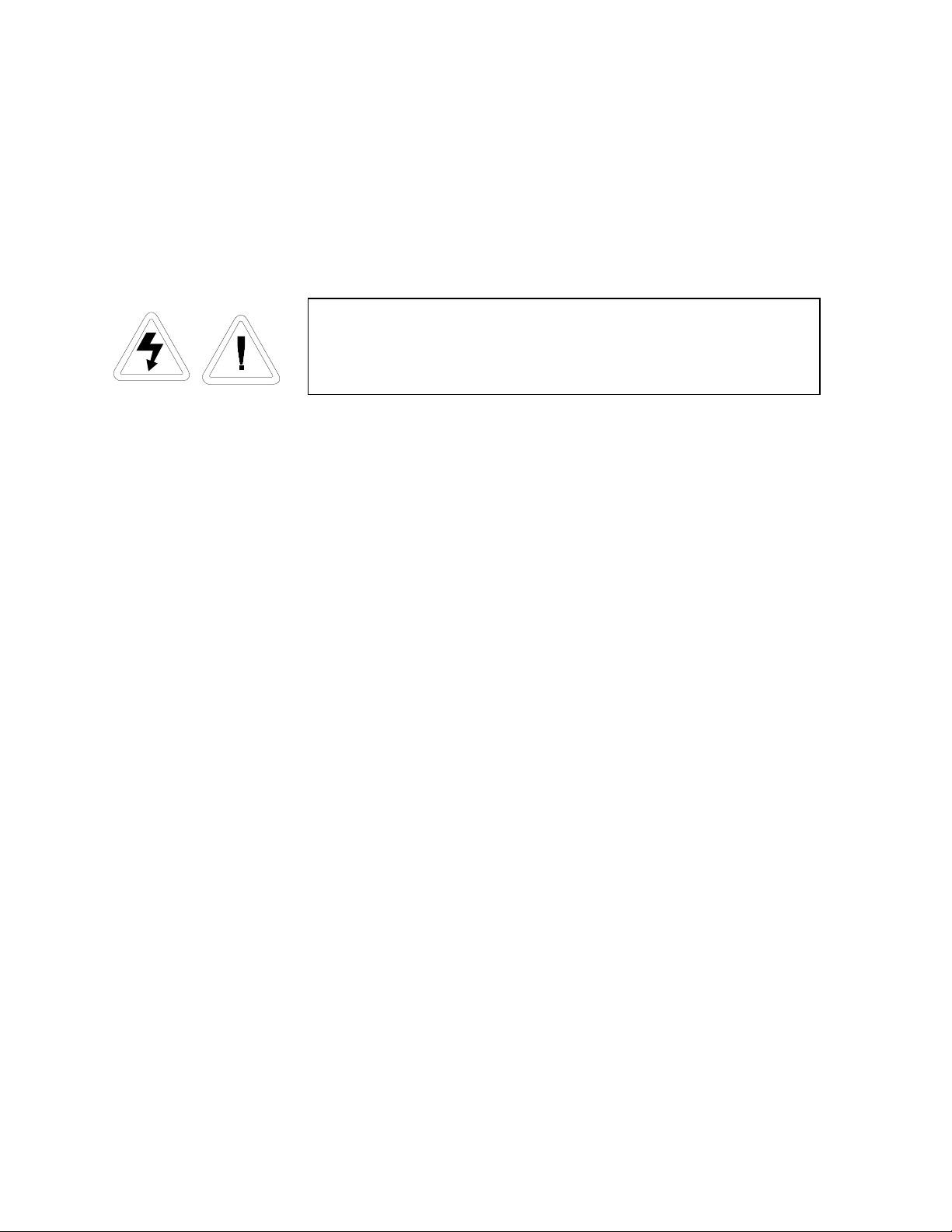
Avoid the excessive use of water around the control area due
to the risk of electrical shock. Damage to the controls may
also result.
1. Wipe down the freezer exterior using soap and water and a general use laboratory
disinfectant.
2. Rinse thoroughly with clean water and dry with a soft cloth.
4.2 Cleaning the Air Filter (minimum of twice a year*)
1. Locate the grille on the right side of control panel. See Figure 1-2 or 1-3. Grasp the
corner of the grille and gently pull to remove.
2. Remove the filter material and wash, using water and mild detergent.
3. Dry by pressing between two towels.
4. Install the filter back into the grille and attach the grille.
* Depending upon environmental conditions, the filter may need to be cleaned or replaced more
frequently. If the filter becomes torn or excessively dirty, a replacement can be purchased from
Forma Scientific. See the Parts List, Section 7, for filter part number. A filter kit (set of 5 filters)
is also available.
4.3 Cleaning the Condenser (minimum of twice a year*)
1. Locate the grille on the right side of control panel. See Figure 1-2 or 1-3. Grasp the
corner of the grille and pull gently to remove.
2. Using a vacuum cleaner, exercising care to not damage the condenser fins, clean the
condenser.
3. Install the grille.
* Depending upon environmental conditions, the condenser may need to be cleaned more
frequently.
4-1
Page 22
Forma Model 700 Series _____________________________________________Maintenance
4.4 Defrosting the Chamber
1. Remove all product and place it in another freezer.
2. Turn the unit off and disconnect it from the power source.
3. Turn the Alarm switch to STANDBY, or disconnect the battery.
4. Open all the doors and place towels on the chamber floor.
5. Allow the frost to melt and loosen.
6. Remove the frost with a soft cloth.
7. After defrosting is complete, clean the interior with a non-chloride detergent. Rinse
thoroughly with clean water and dry with a soft cloth.
8. Plug unit in and turn power switch on.
9. Allow the freezer to operate empty overnight before reloading the product.
4.5 Cleaning the Lid Gasket (minimum monthly*)
1. Using a soft cloth, remove any frost build up from the gasket, sub lids and lid.
*The lid gasket may need to be cleaned more frequently if dirt or excessive frost build-up
prevents the door from closing properly.
4.6 Replacing the Battery
For a consistent and dependable charge, replace the battery every 2 years.
Replacement batteries must be rechargeable and are available from Forma
Scientific. Refer to the parts list for the stock number and description of the
replacement batteries.
Dispose of used batteries in a safe manner and in accordance with good
environmental practices.
4-2
Page 23
Forma Model 700 Series _____________________________________________Maintenance
1. Use the power switch and disconnect the line cord from the receptacl e to turn th e
unit off.
2. To gain access to the battery, remove the grill on the front of the freezer. The grill is
attached to the freezer by friction plugs on each of the four corners and is readily
pulled off. The battery is the rectangle fastened by Velcro to the compressor
compartment frame and has a connector with red and black wires. Another red and
black wire set with connector is secured to the wiring harness passing through this
area of the freezer.
3. Disconnect the two wire connectors, replace the battery pack and secure with the
Velcro.
4. Reconnect the battery and replace the grill.
5. Plug unit in and turn power switch on.
4.7 Preparing the Unit for Storage
Defrost the unit as described in Section 4.4. This will prepare the unit for storage. ο
The battery must be disconnected to prevent the battery from
becoming completely discharged during storage.
4-3
Page 24
Forma Model 700 Series ______________________________________________Service
Section 5 - Service
4.1 Servicing the Refrigeration System
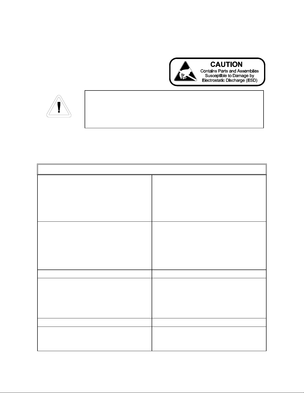
Servicing must be only performed by service personnel qualified to
repair cascade refrigeration systems. Always use standard safety
practices when servicing any equipment.
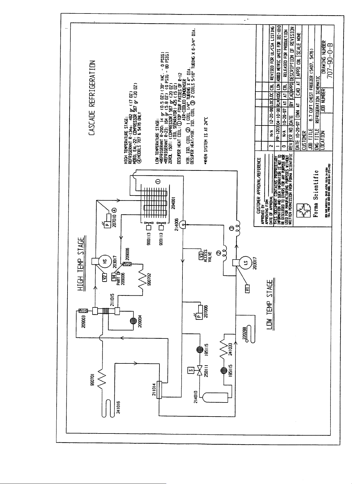
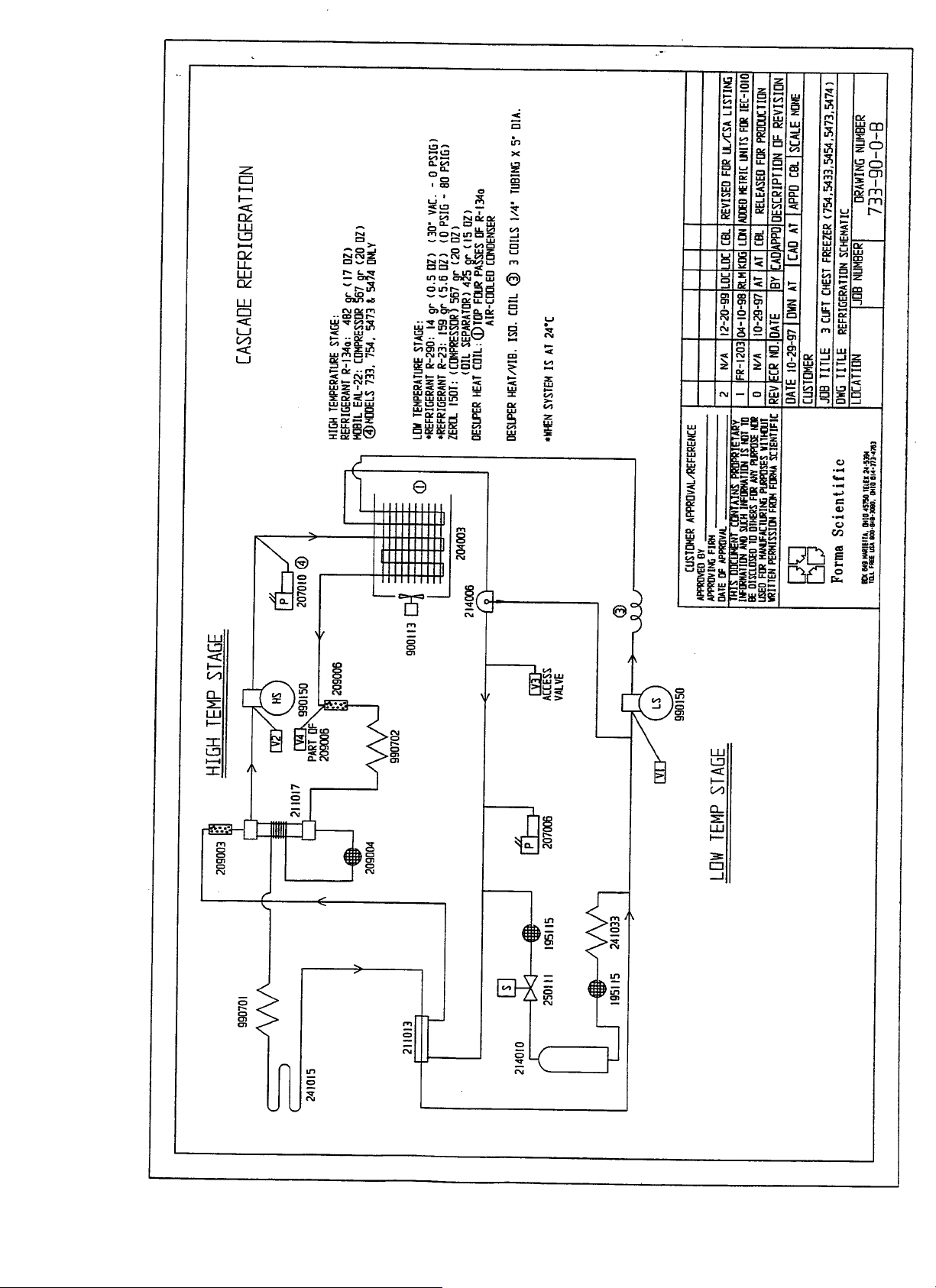
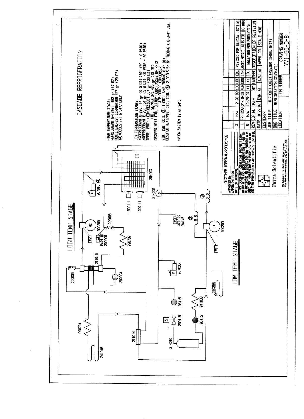
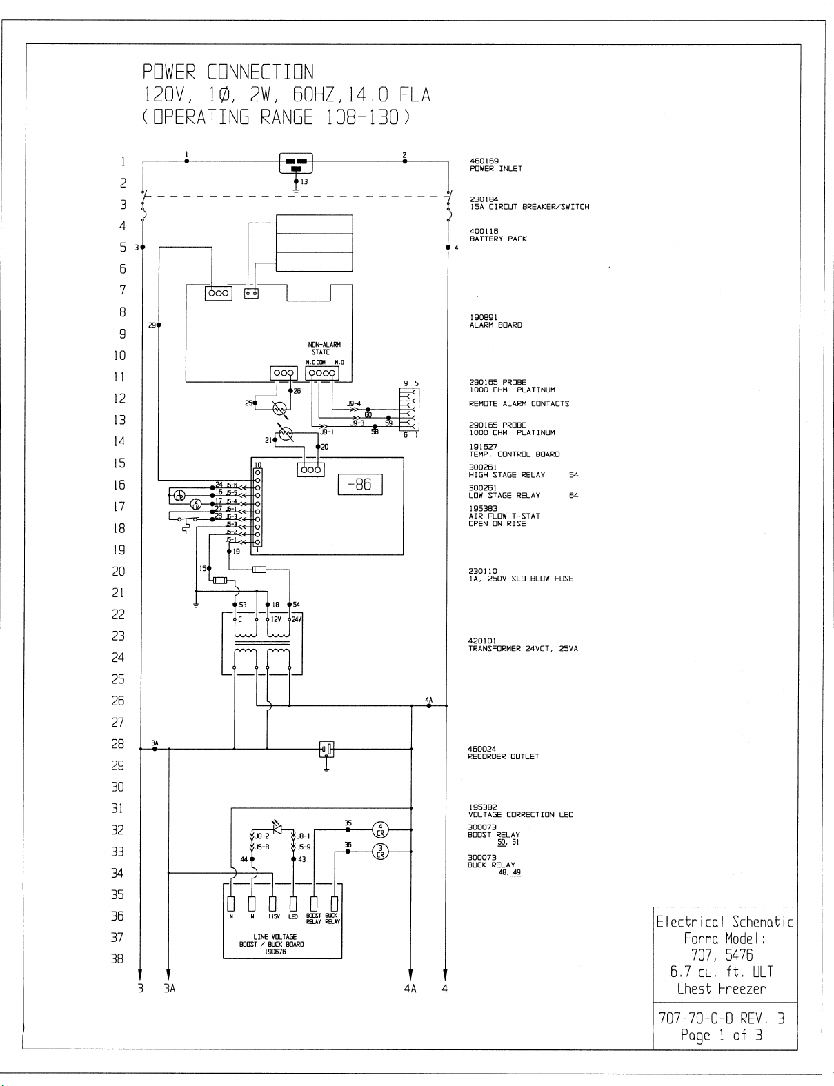
Before opening the refrigeration system, use the troubleshooting chart below to check
out the electrical system. Electrical schematics and refrigeration drawings with part numbers
are included in this manual.
Symptom Possible Cause
No Temperature Display. • Power line cord disconnected or not
properly installed.
• External power circuit breaker
tripped/open.
• Main power switch OFF.
• 24V transformer fuses open.
Chamber Temperature Deviates from
Setpoint.
Too Much Frost Build-Up. • Lid not properly sealed
Freezer not Being Refrigerated
(Unit is receiving Power).
Display Problems in General. • Defective temp control board.
Condenser Hot Light On • Dirty air filter.
• Too much warm product added.
• Lid open too long.
• Inadequate air circulation.
• Unit is out of calibration.
• Dirty condenser.
• High ambient temperature.
• Compressor thermal overload open.
• Defective temp control.
• Defective high pressure cut-off.
• Defective compressor(s).
• Loss of refrigerant.
• Dirty condenser fan.
• Fan failure.
5-1
Page 25
Forma Model 700 Series _________________________________________Specifications
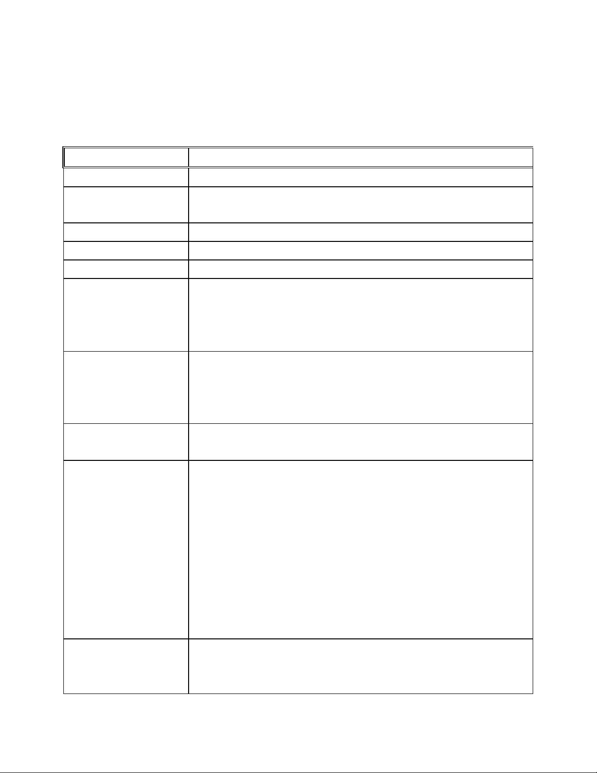
Section 6 - Specifications
3.0 cu. ft. Chest Freezers
Models 733 and 754
Temperature
Exterior Dimensions
Interior Dimensions
Refrigeration
Capacity
Insulation Type: Non-CFC urethane
Electrical 733: 120 VAC, 1PH, 60 Hz, 10.0 FLA
Breaker Requirements
(Dedicated Circuit)
-50°C (-58°F) to –77°C (-106°F)
28.5" W x 41.8" H x 28.8" F-B (72.4cm x 106.2cm x 73.2cm)
Add 6.5" (16.5cm) to F-B for handle/wall spacer
18.5" W x 16.5" H x 18.5" F-B (47cm x 41.9cm x 47cm)
Cascade system, (2) hermetically-sealed compressors
3.0 cu. ft. (85 liters)
Sides: 5.0" (12.70cm)
Lid: 2.0" (5.08cm)
Sub Lid: 1.0" (2.54cm)
Operating Range: 108VAC - 130VAC
754: 230 VAC, 1 PH, 50 Hz, 8.0 FLA
Operating Range: 208VAC - 240VAC
733: 15 Amp , 120V
754: 15 Amp, 230V
Automatic Voltage
Compensator
Shipping Weight
(Non-CFC) Packaging
733:
Low:
Cut in: 110V, Cut out: 115V, Volts Boost: 10
High:
Cut in: 125V, Cut out: 120V, Volts Buck: 10
754: (Compressor only)
Low:
Cut in: 95V, Cut out: 100V, Volts Boost: 10
High:
Cut in: 110V, Cut out: 105V, Volts Buck: 10
Ocean: 450 lbs. (204 kg)
Air/Container: 412 lbs. (187 kg)
Motor: 375 lbs. (170 kg)
6-1
Page 26
Forma Model 700 Series _________________________________________Specifications
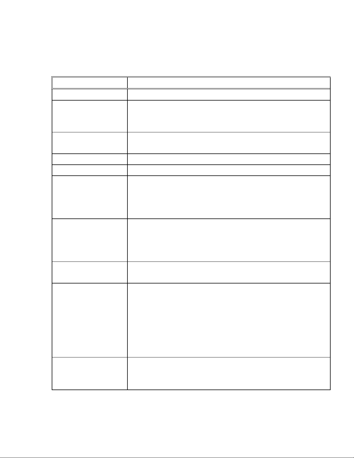
6.7 cu. ft. Chest Freezers
Models 707 and 771
Temperature -50°C (-58°F) to -86°C (-123°F)
Exterior Dimensions 48" W x 41.8" H x 28.8" F-B
(121.9cm x 106.2cm x 73.2cm)
Add 6.5" (16.5cm) to F-B for handle/wall spacer
Interior Dimensions 38.0" W x 16.5" H x 18.5" F-B
(96.5cm x 41.9cm x 47cm)
Refrigeration Cascade system, (2) hermetically-sealed compressors
Capacity 6.7 Cu. Ft. (190 liters)
Insulation
Electrical
Breaker Requirements
(Dedicated Circuit)
Automatic Voltage
Compensator
Type: Non-CFC urethane
Sides: 5" (12.7 cm)
Lid: 2" (5.08 cm)
Sub Lid: 1" (2.54 cm)
707: 120 VAC, 1PH, 60 Hz, 14 FLA
Operating Range: 108VAC - 130VAC
771: 230 VAC, 1 PH, 50 Hz, 8 FLA
Operating Range: 208VAC - 240VAC
707: 20 Amp , 120V
771: 15 Amp, 230V
Low:
Cut in: 110V, Cut out: 115V, Volts Boost: 10
Cut in: 210V, Cut out: 220V, Volts Boost: 18
High:
Cut in: 125V, Cut out: 120V, Volts Buck: 10
Cut in: 235V, Cut out: 225V, Volts Buck: 18
Shipping Weight
(Non-CFC) Packaging
Ocean: 600 lbs. (272 kg)
Air/Container: 565 lbs. (256 kg)
Motor: 492 lbs. (223 kg)
6-2
Page 27
Forma Model 700 Series _______________________________________________Parts
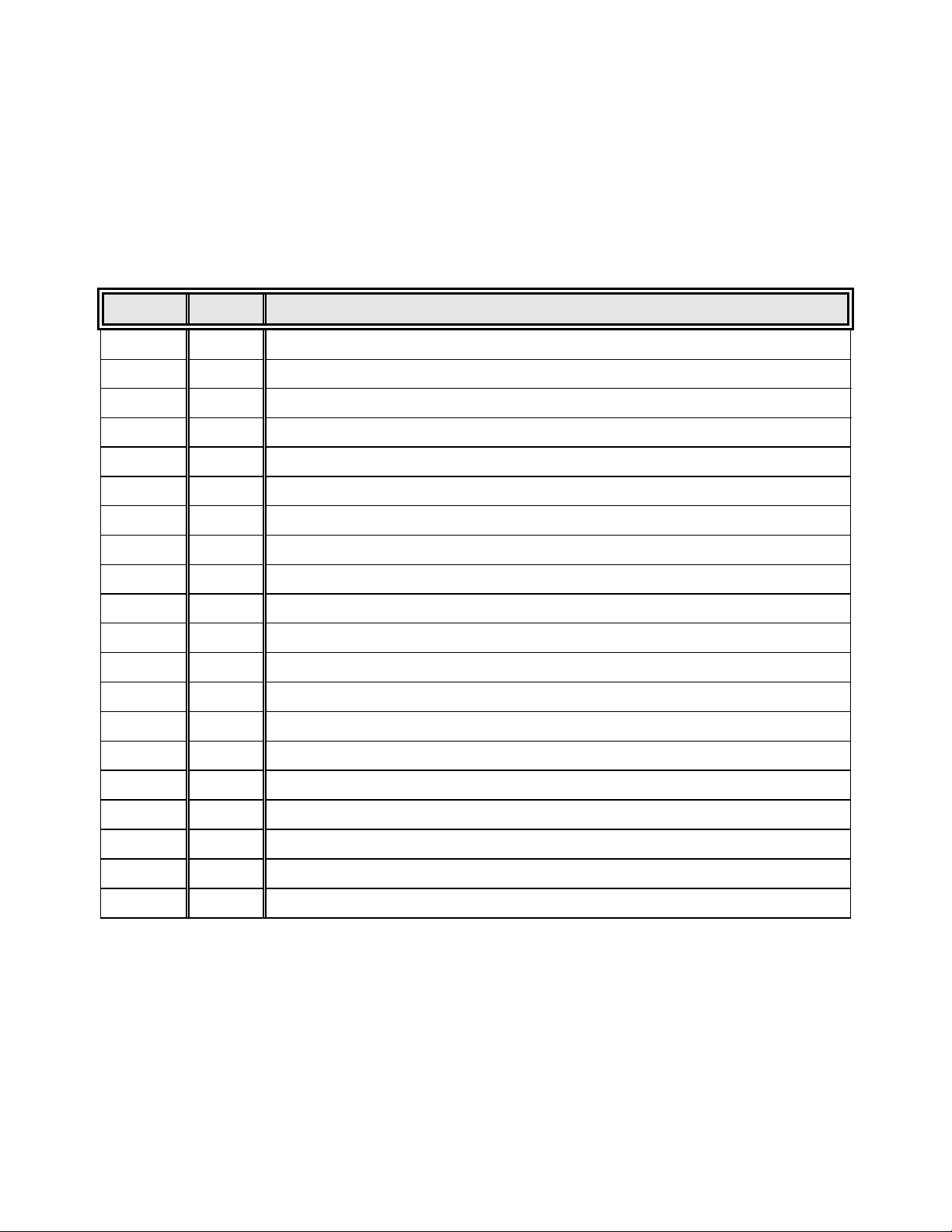
Section 7 - Parts List
Models 733 and 754 (3.0 cu. ft. models)
Stock # Qty Description
191627 1 Temperature Control Board
195383 1 Thermostat 40°C
290165 1 Temperature Monitor Probe
400116 1 Battery, Dryseal pack 3.6V, AA
214006 1 Oil Separator
209003 1 Dryer 3/8 ODF
209006 1 Dryer 1/4 ODS
250111 1 Solenoid Valve, 120V
207010 1 Pressure Switch, Cutout (high pressure cut-out @ 350 PSIG)
900113 1 Tubeaxial Fan, 120V
760198 1 Air Filter, 11.4” x 14.4”
230110 2 1.0 Amp Fuse, Slo-Blow (Transformer)
420101 1 Transformer, 25 VA, 24Volt
1990150 1 Low Stage Compressor with Zerol 150T, 120V,1/4 HP (Models 733 & 754)
2990150 1 High Stage Compressor with Ester Oil, 120V, 1/4 HP (Models 733 & 754)
970023 70# cyl Refrigerant R-134A, High Stage
970022 70# cyl Refrigerant R-23, Low Stage
970009 14.5 oz Propane
970010 1 Propane Tank Adapter
143021 1 gal Zerol 150T
7-1
Page 28
Forma Model 700 Series _______________________________________________Parts
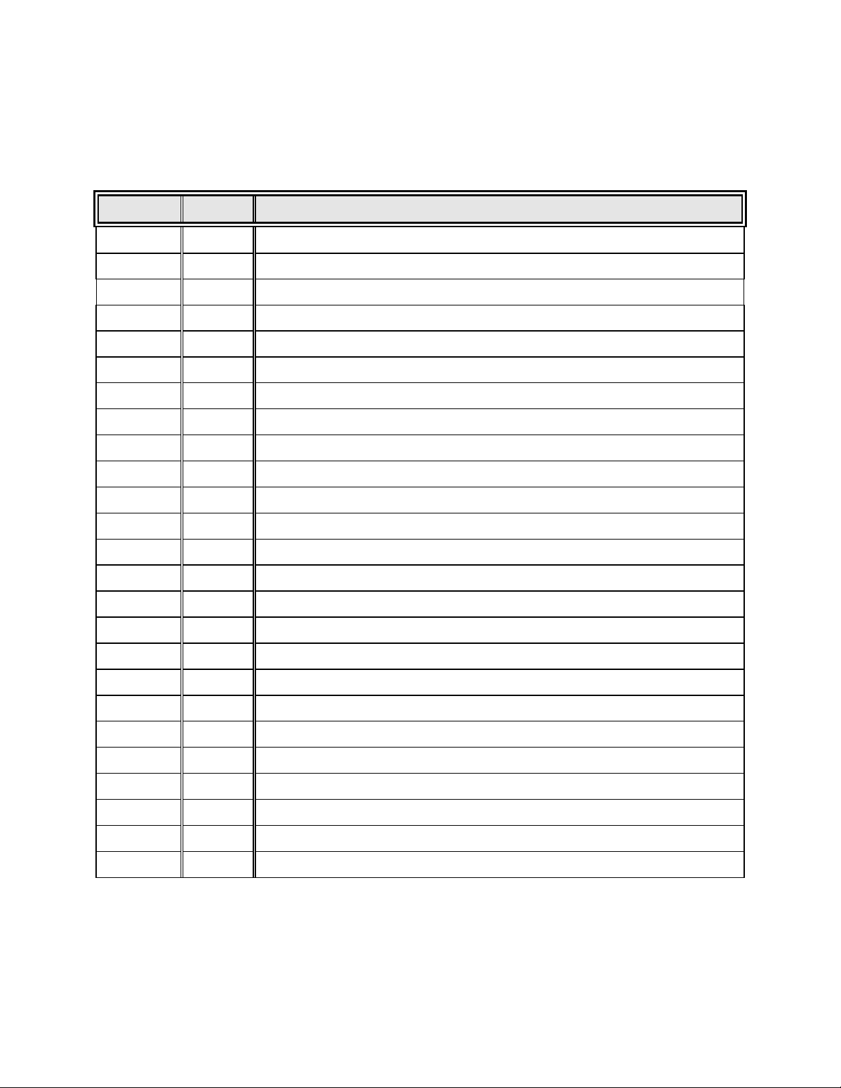
Models 707 and 771 (6.7 cu. ft. models)
Stock # Qty Description
191627 1 Temperature Control Board
195383 1 Thermostat 40°C
290165 1 Temperature Monitor Probe
400116 1 Battery, Dryseal pack 3.6V, AA
214006 1 Oil Separator
209003 1 Dryer 3/8 ODF
209006 1 Dryer 1/4 ODS
250111 1 Solenoid Valve, 120V
250115 1 Solenoid Valve (230V models only)
207010 1 Pressure Switch, Cutout (high pressure cut-out @ 350 PSIG)
900113 2 Tubeaxial Fan, 120V (Model 707)
900111 2 Tubeaxial Fan, 230V (Model 771)
760165 1 Air Filter, 11.4” x 25.9”
195519 1 (5) 760165 Air Filters
230110 2 1.0 Amp Fuse, Slo-Blow (Transformer)
420101 1 Transformer, 25 VA, 24Volt
1990209 1 Low Stage Compressor with Zerol 150T, 230V, 1/3 HP (Model 771)
2990209 1 High Stage Compressor with Ester Oil, 230V, 1/3 HP (Model 771)
1203017 1 Low Stage Compressor with Zerol 150T, 120V, 1/3 HP (Model 707)
2203017 1 High Stage Compressor with Ester Oil, 120V, 1/3 HP (Model 707)
970023 70# cyl Refrigerant R-134A, High Stage
970022 70# cyl Refrigerant R-23, Low Stage
970009 14.5 oz Propane
970010 1 Propane Tank Adapter
143021 1 gal Zerol 150T
7-2
Page 29

Forma Model 700 Series _________________________________Refrigeration Drawings
Section 8 - Refrigeration Drawings
8-1
Page 30
Page 31
Page 32
Page 33

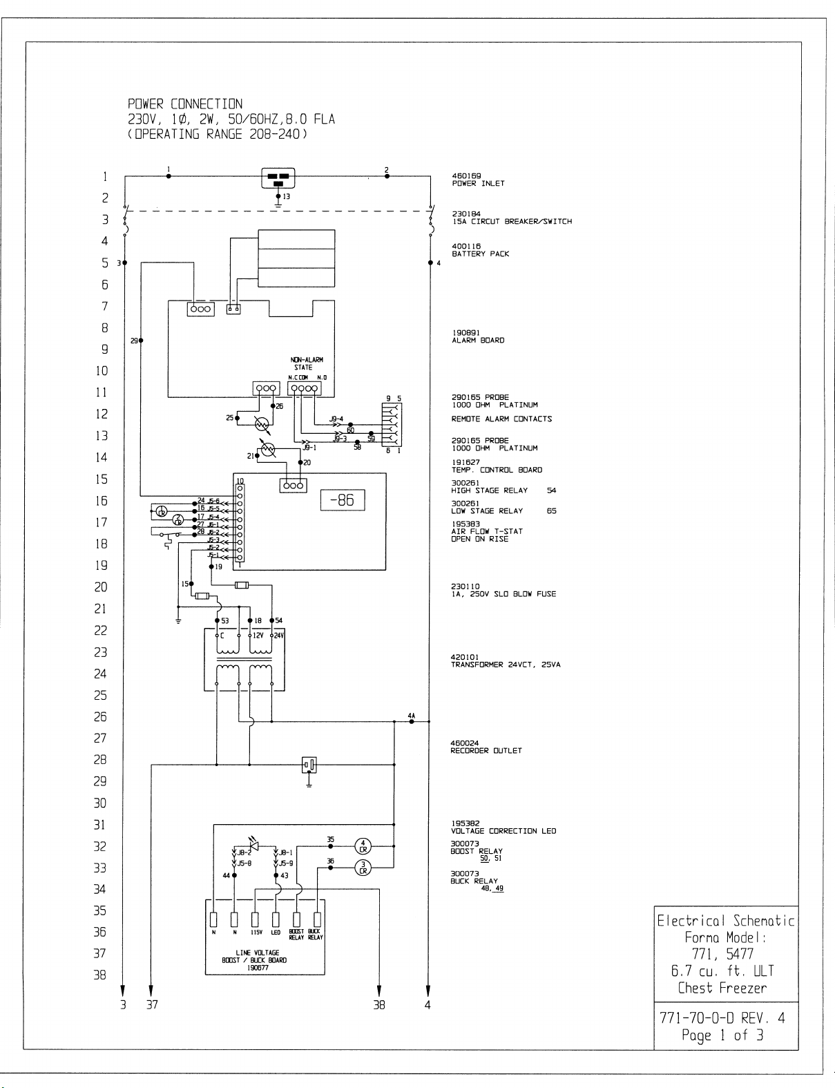
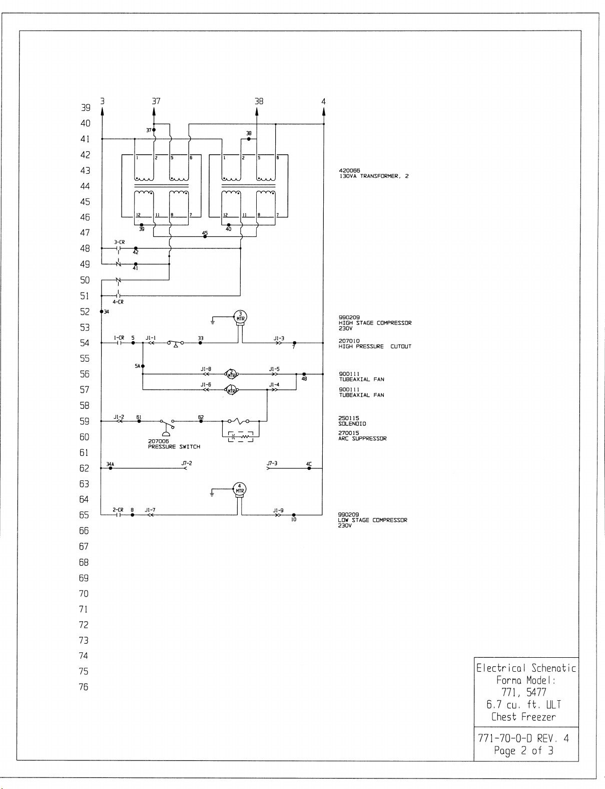
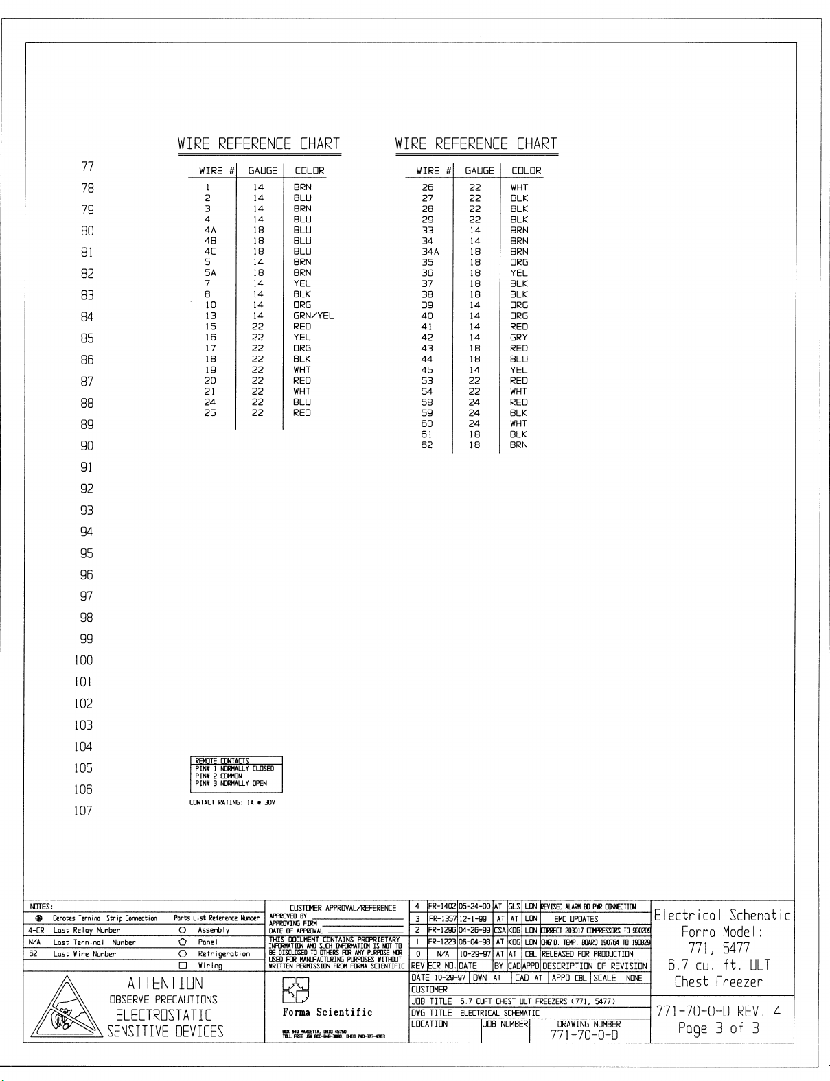
Forma Model 700 Series ___________________________________Electrical Schematics
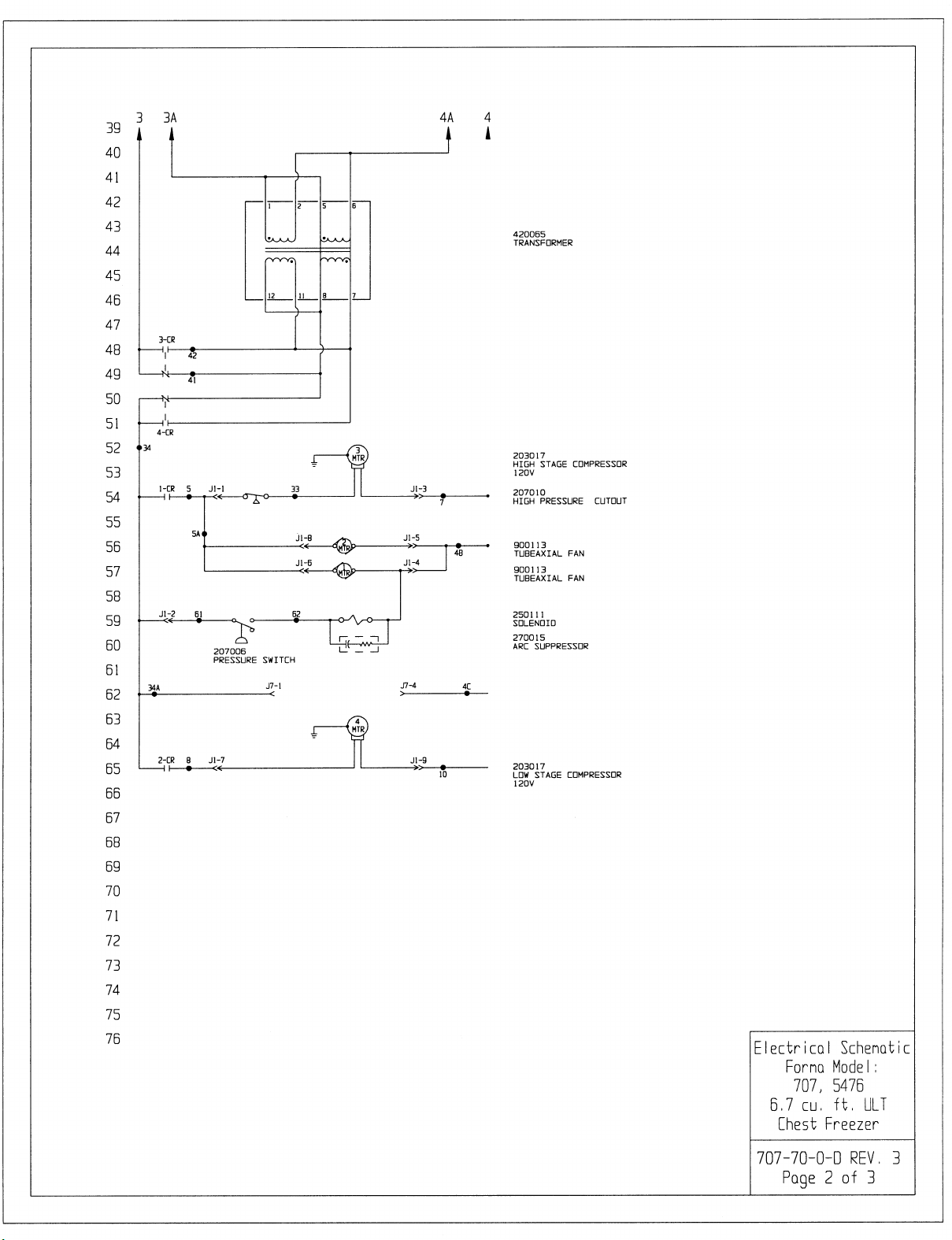
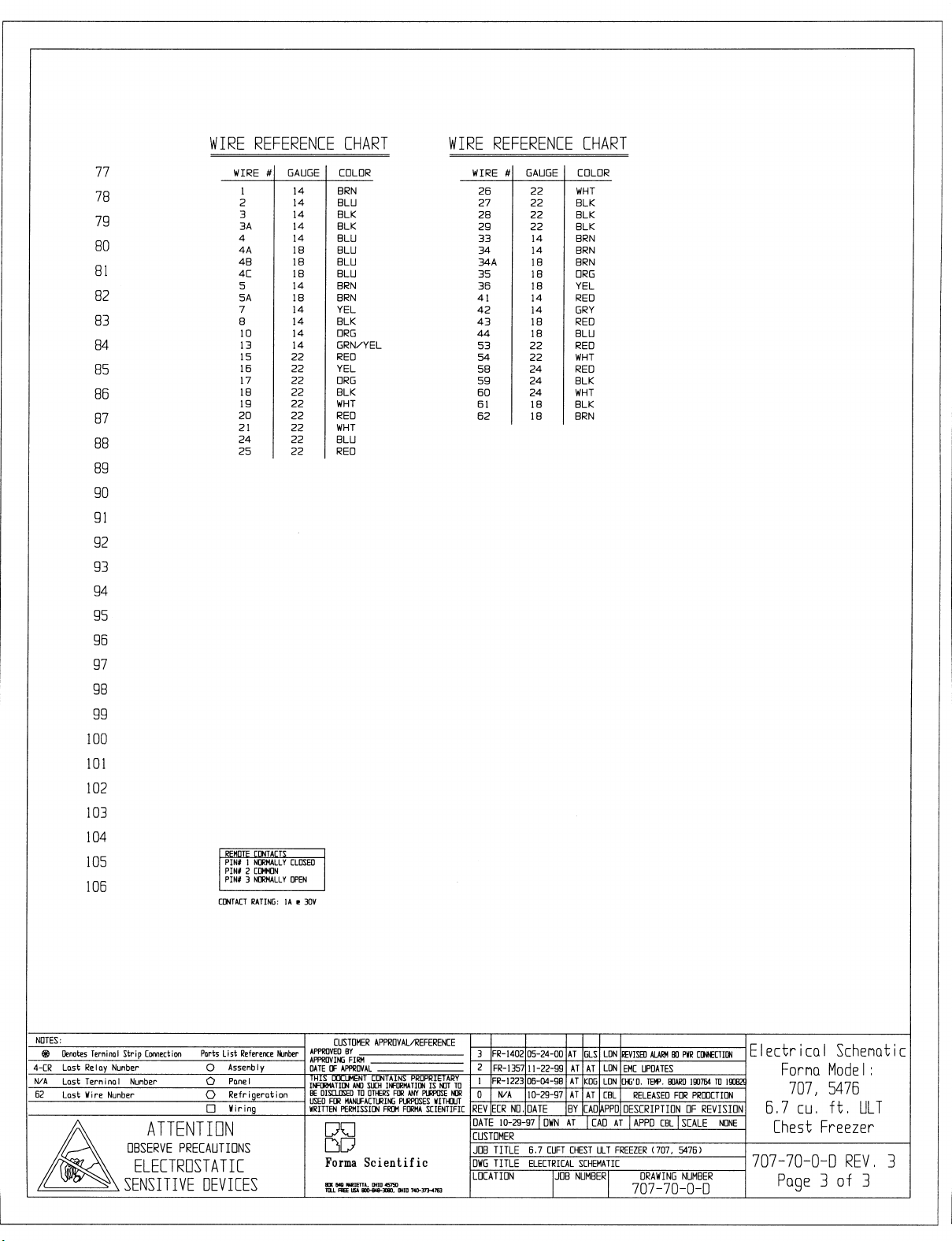
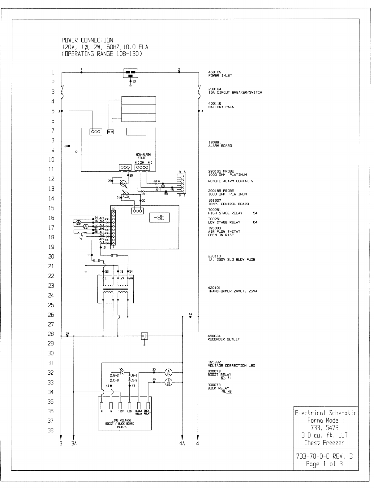
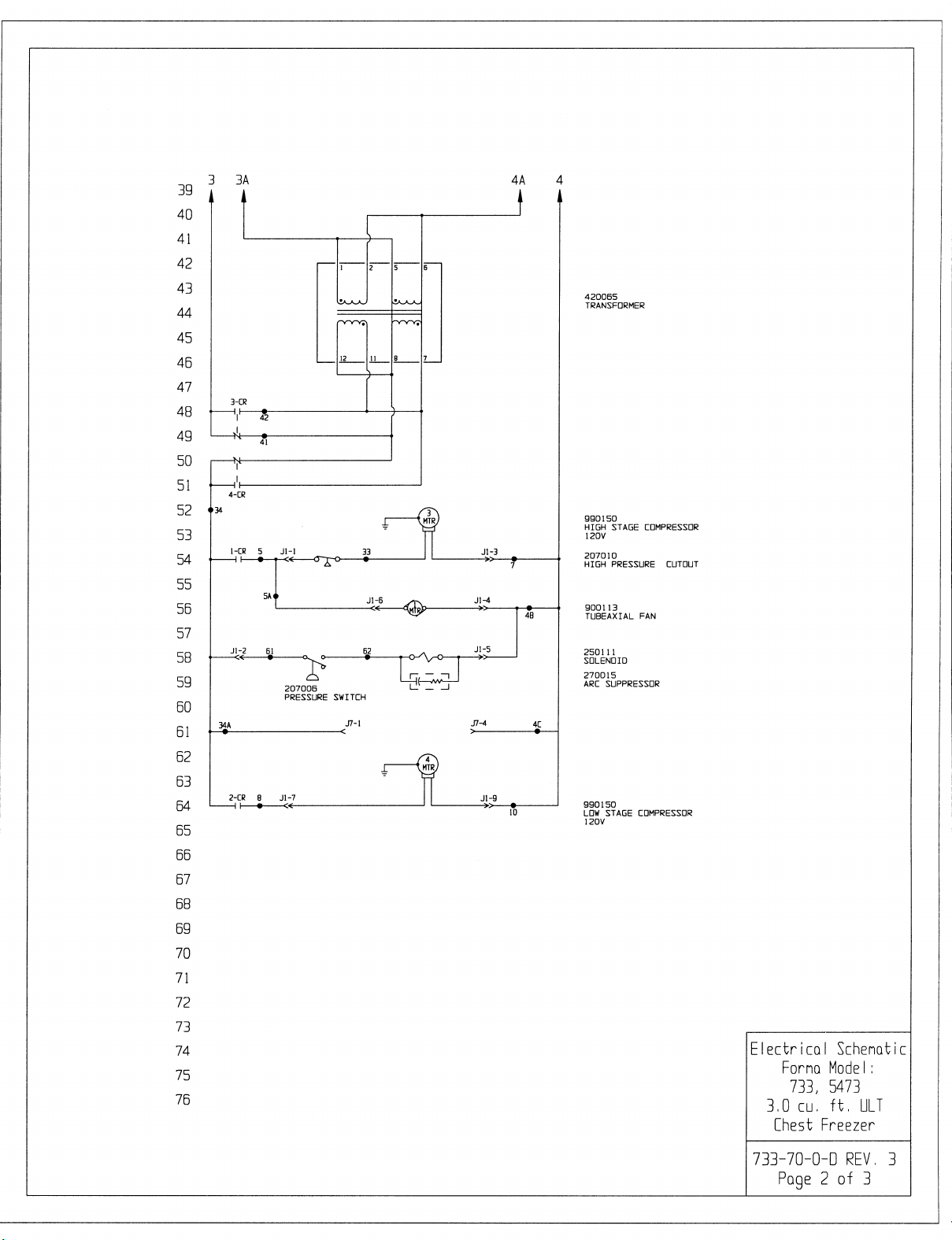
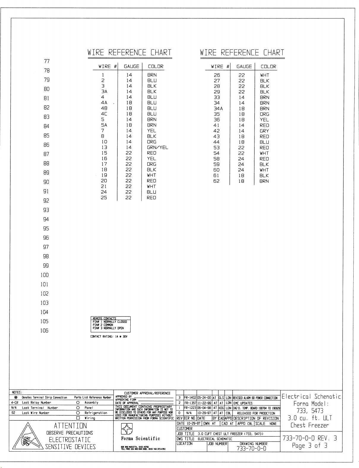
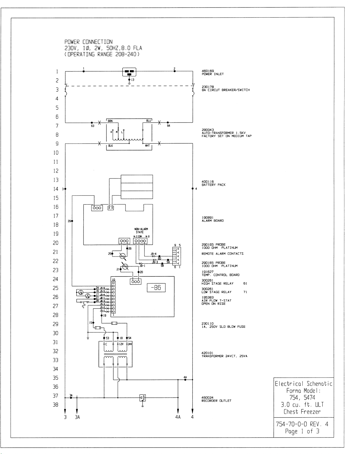
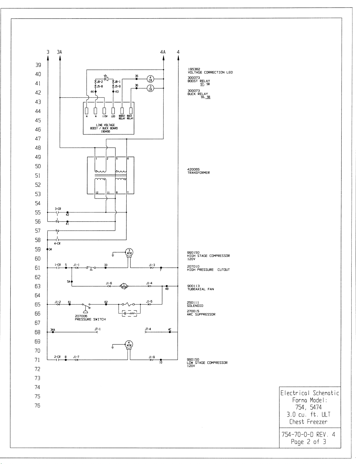
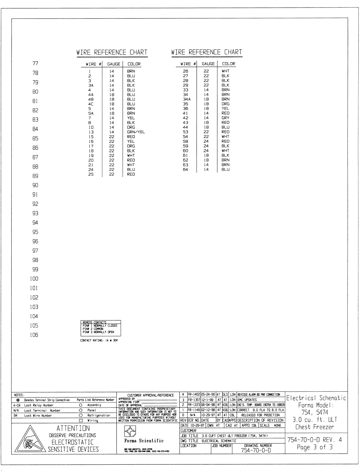
Section 9 - Electrical Schematics
9-1
Page 34
Page 35
Page 36
Page 37
Page 38
Page 39
Page 40
Page 41
Page 42
Page 43
Page 44
Page 45
 Loading...