

for Living Kitchen Cart 068-1303-4 Assembly Instructions Manual
Kitchen Cart
Model No. 068-1303-4
®
D
Assembly Instructions
Toll-free: 1-877-483-6759
IMPORTANT: Please read and understand this manual before any assembly. Before beginning
assembly of product, make sure all parts are present. Compare parts with packaging contents
list. If any part is missing, or if you have any questions, contact the service centre
at: 1-877-483-6759 (toll-free).

Step 1 - requires E, F, I, G, H, P
Made in China
Imported by Trileaf Distribution Trifeuil Toronto, Canada M4S 2B8

Step 9 - requires W, X
Table of Contents 3
Important Safety Instructions 3
®
3
D
Parts List
Assembly 6
4
Warning! To reduce the risk of serious injury, read the following safety instructions before assembling
and using this product.
• This product is intended for indoor use.
•
The product should be placed on at, horizontal ground.
• Any assembly or maintenance of the product must be carried out by adults only.
•
Plastic bags can be dangerous. To avoid danger of suffocation, keep this bag away from babies and children.
18Technical Specications
18Warranty
Table of Contents
Important Safety Instructions
IMPORTANT: RETAIN FOR FUTURE REFERENCE, AND READ CAREFULLY.
Step 13
Step 12 - requires N, Z, CC
Model No. 068-1303-4
4
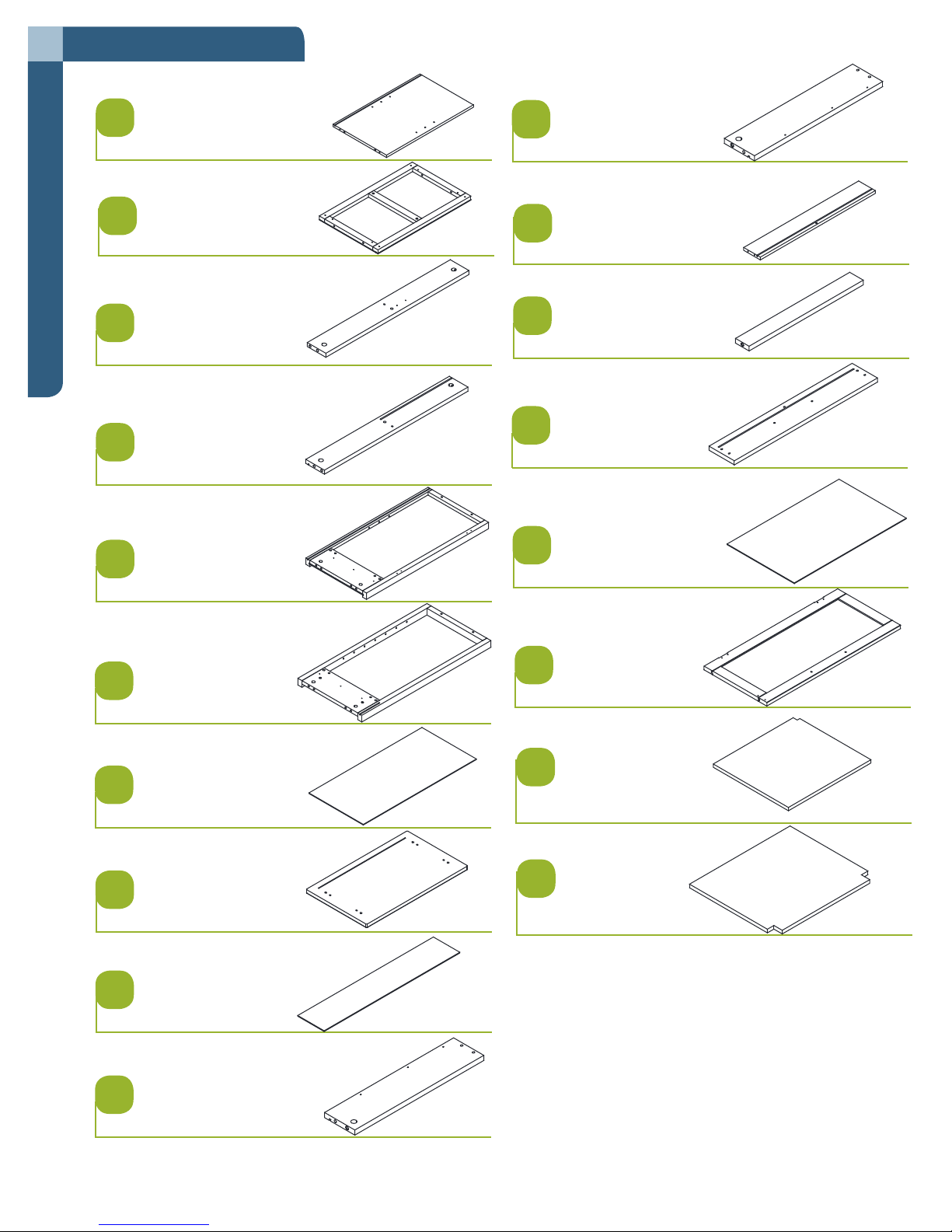
1
Divider panel - 1
2
Bottom - 1
3
Drawer strip - 1
Parts List
4
Back rail - 1
5
Left side frame - 1
11
Right drawer side - 1
12
Drawer back - 1
13
Drawer bottom support - 1
14
Drawer face - 1
15
Drawer bottom - 1
6
Right side frame - 1
7
Lower back panel - 1
8
Top - 1
9
Upper back panel - 1
10
16
Door panel - 1
17
Left adjustable shelf - 1
18
Right adjustable shelf - 2
Left drawer side - 1
®
5
D
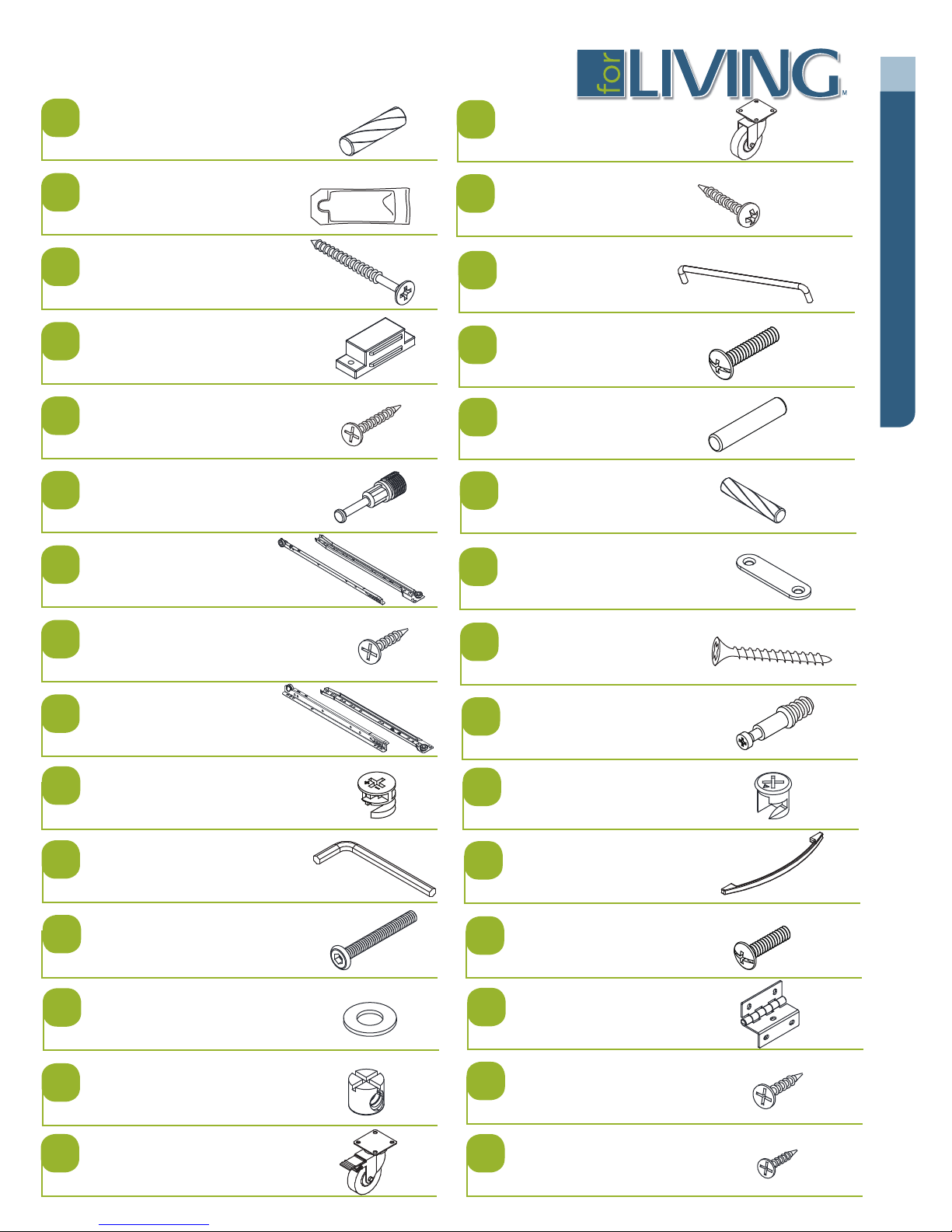
A
Wood dowel 7.8 x 30 mm - 12
B
Glue - 1
C
Screw 5 x 50 mm - 4
D
Magnet - 1
E
Screw 3 x 16 mm - 2
F
Cam bolt (large) - 8
G
P
Castor - 2
Q
Screw 5 x 20 mm - 16
R
Towel bar - 1
S
Bolt M4 x 22 mm - 2
Parts List
T
Shelf pin - 12
U
Wood dowel 5.8 x 30 mm - 2
V
Rail track (left) - 1
H
Screw 3.5 x 12 mm - 12
I
Rail track (right) - 1
J
Cam (large) - 8
K
Hex wrench - 1
L
Bolt M6 x 60 mm - 4
M
Metal washer - 4
Metal plate - 1
W
Screw 3.8 x 35 mm - 5
X
Cam bolt (small) - 3
Y
Cam (small) - 3
Z
Handle - 2
a
Bolt M4 x 20 mm - 4
e
Hinge - 2
N
Crosshead nut - 4
O
Locking castor - 2
f
Screw 3.5 x 12 mm - 10
g
Screw 3 x 10 mm - 2
Model No. 068-1303-4
6
Read each section carefully before starting. It is very important that each step is performed in
the correct order. If these steps are not followed in sequence, assembly difculties will occur.
Make sure all parts are included. Most board parts are labelled or stamped on the raw edge.
Work in spacious area, preferably on a carpet, near the place the unit will be located.
Do not use power tools to assemble your furniture. Power tools may strip or damage the parts.
HELPFUL HINTS
• Identify, sort and count the parts before beginning assembly.
• Compression dowels should be tapped in with a rubber mallet.
• Slides have a lip on the right side only.
• Back panels provide stability and support. Unit may collapse without the back
panel installed.
Clean the product with your choice of furniture polish and a soft cloth. DO NOT USE harsh
Assembly
chemicals or abrasive cleaners.
• Move your new furniture carefully. Two people are needed to lift and carry the unit to its new
location.
• Never push or drag your furniture (especially on a carpet).
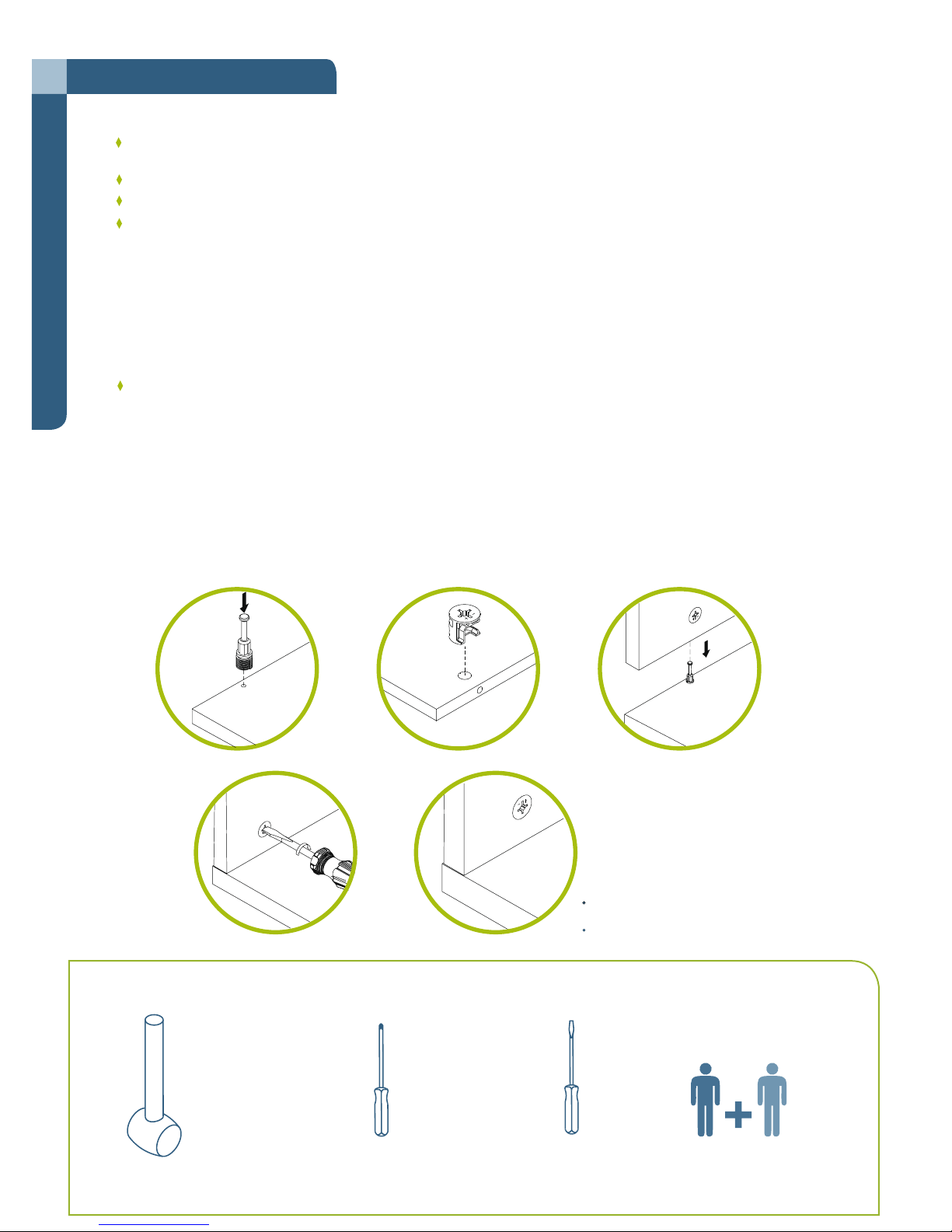
This illustration shows how the cam-fastening system works.
1.
4.
Needed for assembly:
160º~185º
2.
5.
3.
Important Note:
+/- on the cam should be positioned
as shown.
Do not overtighten the cam bolt.
Rubber mallet
Cross-head screwdriver
Flat-head screwdriver
2 people
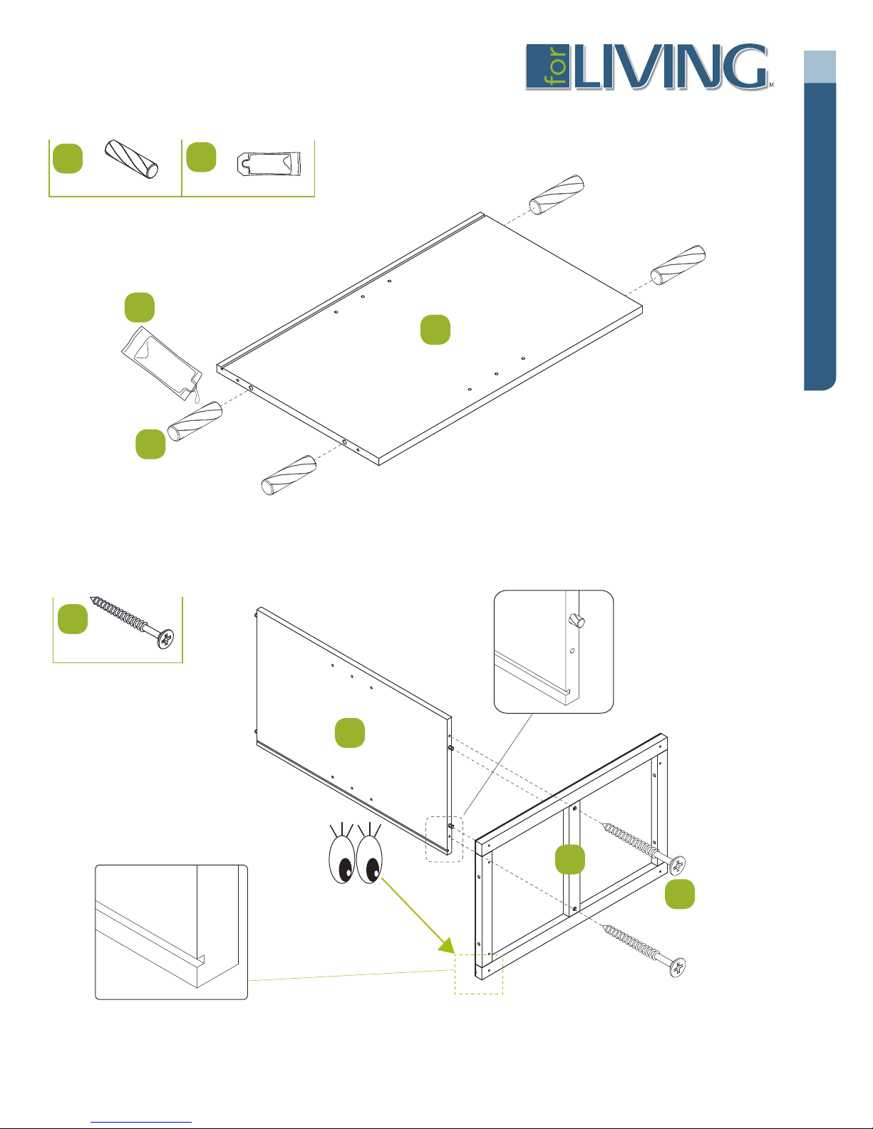
Step 1
Requires 1, A, B
®
7
D
A
Step 2
B
7.8 x 30 mm
B
1
Assembly
A
Requires 1, 2, C
C
5 x 50 mm
1
2
C
Model No. 068-1303-4
8
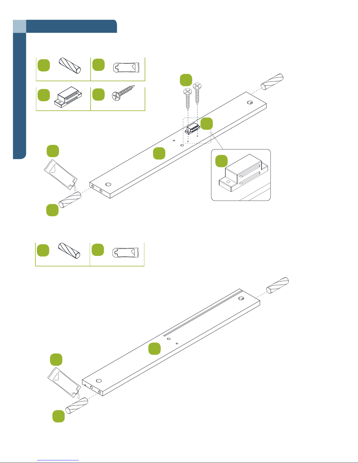
Step 3
Requires 3, A, B, D, E
A
D
Assembly
B
A
Step 4
7.8 x 30 mm
B
E
E
3 x 16 mm
D
3
D
Requires 4, A, B
A
7.8 x 30 mm
B
B
4
A
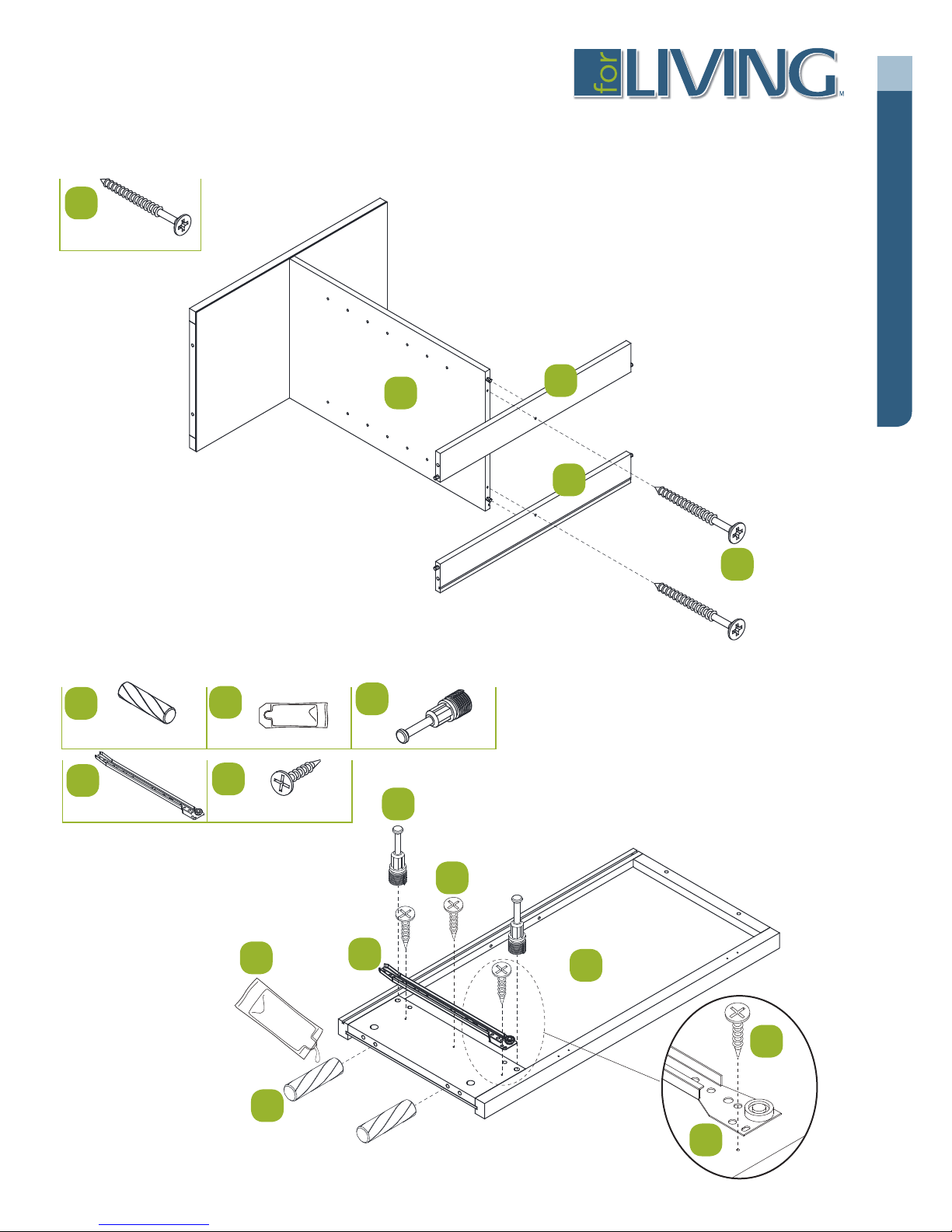
Step 5
Requires 1, 3, 4, C
C
5 x 50 mm
®
9
D
Step 6
Requires 5, A, B, F, G, H
A
7.8 x 30 mm
G
B
H
3.5 x 12 mm
1
3
Assembly
4
C
F
F
B
A
G
H
5
H
G
Model No. 068-1303-4
10
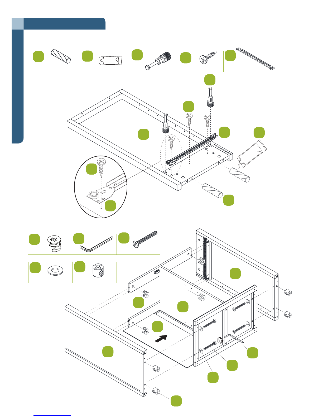
Step 7
Requires 6, A, B, F, H, I
A
7.8 x 30 mm
Assembly
B
H
F
H
3.5 x 12 mm
I
F
H
6
I
B
A
I
Step 8
Requires 1, 5, 6, 7, J, K, L, M, N
J
M
K
N
L
M6 x 60 mm
6
J
1
7
5
K
L
M
N
Step 1 - requires E, F, I, G, H, P
Step 2 - requires C, W, X
Step 5 - r
Step 6 - r
Step 1 - requires E, F, I, G, H, P
Step 5 - r
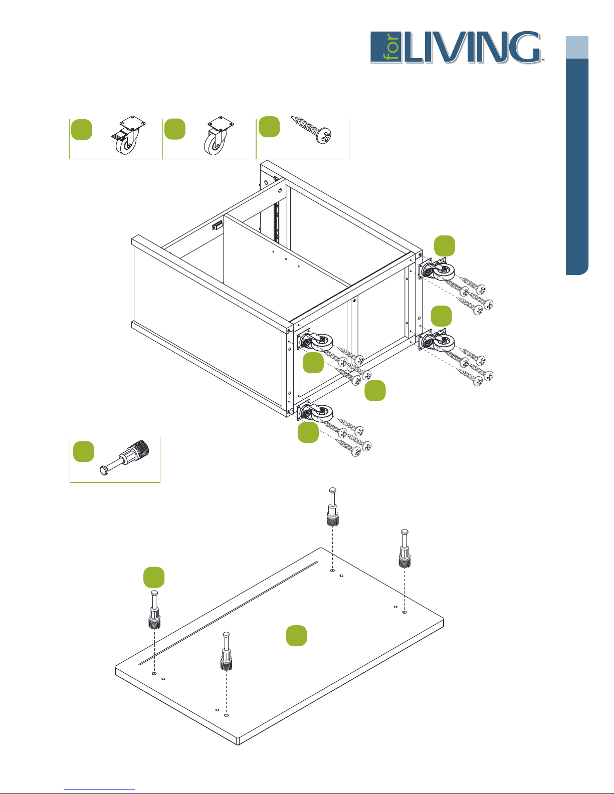
Step 9
Requires O, P, Q
11
®
D
O
Step 10
P
Q
5 x 16 mm
O
Assembly
O
P
Q
Requires 8, F
F
F
P
8
 Loading...