


Acadia Collection Gazebo
Model No. 088-1609-0
Toll-free: 1-877-483-6759
IMPORTANT: Please read this manual carefully before beginning assembly of this product.
Keep this manual for future reference.
Assembly Instructions

3
Caution! Always keep children under close supervision while they are playing around this product.
Never leave children unattended. Keep pets away while setting up the gazebo.
Caution! Check municipal by-laws prior to set ting up the gazebo.
Imported by Trileaf Distribution Trifeuil Toronto, Canada M4S 2B8
Table of ContentsImportant Safety Instructions
Table of contents 3
Important safety instructions 3
Packaging contents 4
Assembly 7
Cleaning and maintenance 23
Technical data 23
Warranty 24
Warning! To re duce the risk of serious injury, read the following safety instructions before
assembling and using the gazebo.
IMPORTANT: RETAIN FOR FUTURE REFERENCE, AND READ CAREFULLY.
This product is intended for domestic outdoor use, i.e. decorative and sunshade purposes only.
Always place and assemble the gazebo on flat horizontal ground.
Consult with your local governing authority and local municipal codes regarding installation of temporary
structures before assembly.
Ensure there is enough clearance around the product. Before assembling the gazebo, make sure to leave
a distance of not less than 1.8 m (6') from any structures or obstructions, such as fences, garages, houses,
overhanging branches, laundry lines, or electrical wires.
Anchor the gazebo to the ground with stakes for added safety. Stakes are provided to secure the gazebo to the
(anchors not included).Do not assemble the gazebo on sandy, muddy or loose soil, as stakes are not strong enough
If more than one gazebo is set up, keep a minimum distance of 3 m (10') between the gazebos.
Any assembly or maintenance of the gazebo must be carried out by adults only.
Make sure there is sufficient manpower when assembling or moving the gazebo.
Some par ts may contain sharp edges
. Wear protective gloves if necessary.
Check all nuts and bolts periodically for tightness. If required, tighten them.
Repairing and replacing parts should be done by a qualified technician.
Always disassemble the gazebo prior to experiencing heavy wind conditions, as it is not designed to withstand
harsh weather, including high wind, rain, and snow and might tip over and could cause injury to bystanders.
Do not hang any weights on the roof frame.
Do not climb onto the roof of the gazebo. Doing so may cause the gazebo to fall down, thereby resulting in
serious injury.
During snow days, remove the snow at the top when the snow is thicker than 4" (10 cm).
Af ter a period of time, usually in 2–3 months, tighten all the bolts.
Af ter a period of use, rinse the ash on the top of gazebo using water. Avoid using acid or alkali wash lotion.
Af ter a few years, if the paint peels off, use paint of similar color. It is recommended to use outdoor paint .
If the gazebo will not be used for a long period of time (e.g. during winter time), disassemble and store it in a
clean, dry environment.
Retain the original packaging to store the gazebo.
Made in China
ground. If you wish to secure the gazebo to a concrete and wood surfaces, use anchors suited for these surfaces
to anchor in these types of soil.
ground. I
f
you wish to secure the gazebo to a concrete and wood sur
f
aces, use anchors suited
f
or these sur
f
aces
gg yp g
4 5
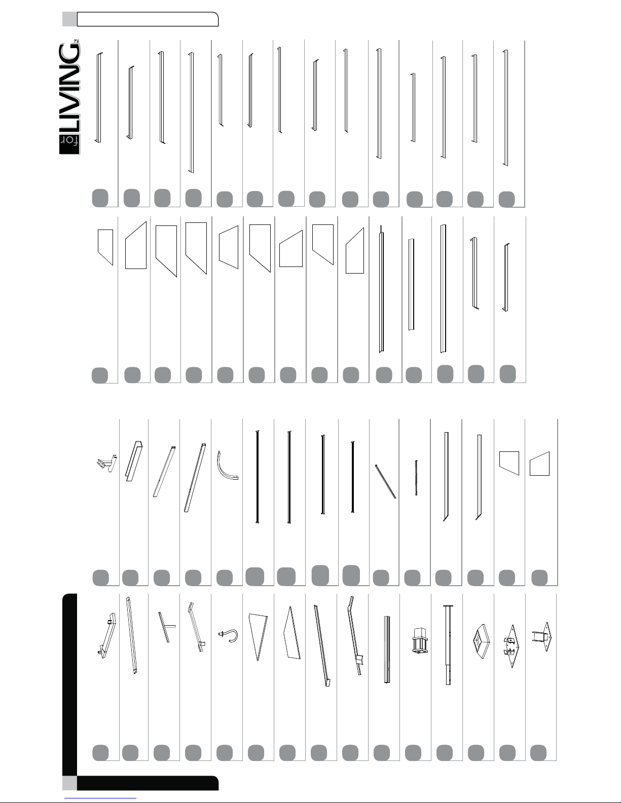
Product No. 08 8-1609-0
Packaging Contents
Long side right roof panel 3 - 2
Short side roof panel 1 - 2
Short side left roof panel 2 - 2
Short side right roof panel 2 - 2
Short side left roof panel 3 - 2
Short side right roof panel 3 - 2
Big roof panel cover (corner) 1 - 4
Big roof panel cover (corner) 2 - 4
Big roof panel cover (middle) - 4
Big roof top beam (short side) (1) - 8
Big roof top beam (short side) (2) - 2
Big roof top beam (long side) (1) - 8
Big roof top beam (long side) (2) - 2
Big roof top beam (long side) (3) - 2
Big roof top beam (long side) (4) - 2
Big roof top beam (long side) (5) - 2
Big roof top beam (long side) (6) - 4
H3
I3
J3
K3
L3
M3
N3
N4
O3
W1
W2
Big top frame - 2 Upper beam connector - 12
Big top bar - 2 Lower beam connector - 8
Small top support beam - 4 Short beam - 2
Small top connector - 1 Long beam - 2
Hook - 1 Arc support - 8
Top roof small panel - 2 Long pipe 1 - 2
Long pipe 2 - 2
Short pipe 1 - 2
Short pipe 2 - 2
Top ro of long panel - 2
Small top cover - 4
Small top roof cover - 1
Post - 4
Top slanting bar - 4
Top beam 1 - 4
Top beam 2 - 4
Top beam 3 - 4
Post connector - 4
Beam connector - 8
Base cover - 4
Base - 4
A1G2B1 H2
C1 I2
D1 J2
E1 K2
L2a
L2b
F1
G1
H1
I1
A2
A3
B3
B2
C2
D2
E2
Small roof top beam (short side) 1 - 2
Small roof top beam (short side) 2 - 2
Q1
Q2
Slanting bar connector - 4
F2
B4
B5
X1
X2
X3
X4
X5
X6
Small roof top beam (long side) 1 - 2
R1
M2a
M2b
Packaging Contents
Long side left roof panel 2 - 2
Long side right roof panel 2 - 2
E3
F3
Long side left roof panel 3 - 2
G3
Long side left roof panel 1 - 2
Long side right roof panel 1 - 2
C3
D3
4
Big roof top beam (short side) (4) - 2
4
Big roof top beam (short side) (5) - 2
4
Big roof top beam (short side) (6) - 4
W4
W5
W6
Small roof top beam (long side) 2 - 2
R2
4
Big roof top beam (short side) (3) - 2
W3

Caution!
Proper placement of gazebo is essential. Do not place the gazebo underneath electrical
lines.
Keep children under close supervision while they are playing around this product. This
product contains small parts which can be swallowed by children.
Keep fingers away from places where they can be pinched or trapped.
Do not attempt to assemble the gazebo if any part is missing.
Let us help you!
DO NOT RETURN YOUR PRODUCT TO THE STORE. CALL US FIRST!
1-877-483-6759
If you have questions regarding your product, require warranty assistance,
or have damaged or missing parts, please call our customer service toll-free helpline.
Contact us for assistance; we’re here to help.
IMPORTANT: Please read and understand this manual before any assembly. Before beginning the assembly of
product, make sure all parts are available. Compare parts with packaging contents list. If any part is missing, or if
you have any questions, contact the service centre at 1-877-483-675 9 (toll-free).
Take all parts from the packaging box and position them on a clean floor. Remove all packing materials and place
them back into the box. Do not dispose of the packing materials until assembly is complete. Read each step
carefully before beginning any assembly and make sure you understand each step. If any part is missing, please
call our toll-free number for assistance: 1-877-483-6759
.
Needed for assembly:
Hammer Screwdriver Ladders (2 m tall)5 people
Assembly
6 7
Product No. 08 8-1609-0
M6 x 15 Screw - 180 + 9 spare
M6 Large flat washer -
M6 x 55 Screw - 36 + 2 spare
M6 Nut - 68 + 3 spare
M6 x 40 Screw - 24+ 2 spare
M6 x 15 Bolt - 84 + 4 spare
M6 x 65 Bolt - 32+ 2 spare
M6 x 20 Bolt - 32+ 2 spare
M6 x 45 Screw - 2
M6 Wrench - 2
M6 x 45 Bolt - 32+ 2 spare
Stake - 16
AA
BB
CC
DD
EE
FF
GG
KK
LL
Z
HH
JJ
Packaging Contents
454+ 23 spare

8 9
Product No. 08 8-1609-0
Note: When using screws and nuts to assemble the product, always use a flat washer between the frame
and the screw and/or nut. This will protect the parts from tear and wear.
Step 1
Requires A1, B1, BB, FF
Step 2
Requires A1, C1, B, F
Attach big top frame (A1) with big top bar (B1) using M6 x 15 bolt (FF) and M6 large flat washer (BB).
FF
BB
B1
A1
C1
A1
BB
BB FF
Attach one end of small top support beam (C1) with the connector of big top frame (A1) using M6 x 15 bolt (FF)
and M6 large flat washer (BB).
BB FF
Step 3
Requires C1, D1, BB, CC, DD
D1
DD
CC
Step 4
Requires D1, E1
D1
E1
Attach the other end of the small top support beam to the small top connector (D1) using M6 nut (DD),
M6 large flat washer (BB) and M6 x 55 screw (CC).
Insert and screw the hook (E1) tightly into the corresponding hole on the small top connector (D1).
BB CC
DD
Assembly
Assembly

10 11
Product No. 08 8-1609-0
Step 5
Requires C1, Q2, R2, AA, BB
Step 6
Requires C1, Q1, R1, AA, BB
Attach the small roof top beam (short side) 2 (Q2) and the small roof top beam (long side) 2 (R2) to the small
top support beam (C1) using M6
x 15 screw (AA) and washer (BB).
R2
C1
Q2
Q1
R1
C1
AA BB
AA BB
Attach the small roof top beam (short side) 1 (Q1) and the small roof top beam (long side) 1 (R1) to the small
top support beam (C1) using M6
x 15 screw (AA) and washer (BB).
Step 7
Requires C2, G2, H2, I2, J2, BB, DD, GG, Z
C2
I2
C2
J2
19
C2
C2
G2
H2
GG
Step 8
Requires B2, C2, BB, KK
Attach beam connector (C2) to the post connector (B2) using M6 x 20 bolt (KK) and washer (BB).
B2
KK
C2
BB KK
DD
GG
Z
BB
(7a) Insert the short beam (I2) and the long
beam (J2) between the beam connectors (C2).
(7b) Attach the upper beam connector (G2) to the lower
beam connector (H2) using M6
x 65 bolt (GG),
washer (BB) and nut (DD). Tighten using the
wrench (Z).
Assembly
Assembly

12 13
Product No. 08 8-1609-0
Step 9
Requires B2, F2, BB, FF
B2
F2
FF
Step 10
Requires G2, I2, J2, BB, FF
FF
J2
G2
I2
BB FF
Attach slanting bar connector (F2) to the post connector (B2) using M6 x 15 bolt (FF) and washer (BB).
Attach upper beam connector (G2) to the short beam (I2) and long beam (J2) using M6
x 15 bolt (FF) and
washer (BB).
BB FF
Step 11
Requires A1, A3, B3, BB, FF
FF
A1
B3
A3
Attach one end of the top slanting bar (A3) and the top beam (B3) to the big top frame (A1) using
M6
x 15 bolt (FF) and washer (BB).
Step 12
Requires A3, B3, F2, G2, BB, CC, DD
A3
CC
F2
G2
CC
B3
(12a) Attach the other end of top slanting bar (A3)
to the slanting bar connector (F2) using
M6
x 55 screw (CC), washer (BB) and
nut (DD).
(12b) Attach the other end of the top middle
beam (B3) to the upper beam connector (G2)
using M6
x 55 screw (CC), washer (BB) and
nut (DD).
BB
FF
BB
CC
DD
BB
CC
DD
Assembly
Assembly

14 15
Product No. 088-1609-0
Step 13
Requires A3, B4, B5, BB, FF
FF
B4
B5
Step 14
Requires B4, B5, G2, BB, CC, DD
B4
G2
CC
B5
BB FF
BB CC
DD
Attach the ends of top side beams (B4, B5) to the slanting bar connector (A3) using M6 x 15 bolt (FF) and
washer (BB).
Attach the other ends of the top side beams (B4, B5) to the upper beam connector (G2) using M6
x 55 screw (CC),
washer (BB) and nut (DD).
Step 15
Requires F1, G1, AA, BB
F1
G1
AA
Step 16
Requires C1, D1, H1, I1, BB, EE, LL, Z
AA BB
Place the top roof small panel (F1) and the top roof long panel (G1) onto the small top support beam and attach
using M6
x 15 screw (AA) and washer (BB).
H1
H1
C1
EE
I1
LL
D1
(16a) Place the small top cover (H1) onto the small
top support beam (C1) and attach using
M6
x 40 screw (EE) and washer (BB). Tighten
using the wrench (Z).
(16b) Place the small top roof cover (I1) onto the
small top connector (D1) and attach using
M6
x 45 screw (LL) and washer (BB). Tighten
using the wrench (Z).
BB BB
LL Z
EE Z
Assembly
Assembly

16 17
Product No. 08 8-1609-0
Step 17
Requires W1, W2, W3, W4, W5, W6, AA, BB
Attach the big roof top beams (short side) (W1, W2, W3, W4, W5, W6) to the big top frame using
M6
x 15 screw (AA) and washer (BB).
BB
AA
Step 18
Requires X1, X2, X3, X4, X5, X6, AA, BB
Attach the big roof top beams (long side) (X1, X2, X3, X4, X5, X6) to the big top frame using M6 x 15 screw (AA) and
washer (BB).
AA
W1
W2
W3
W5
W6
W4
X1
X4
X2
X3
X5
X6
AA
BB
AA
Step 19
Requires B3, L2a, L2b, AA, BB
Attach the one end of long pipes (L2a, L2b) to the top beam (B3) using M6 x 15 screw (AA) and washer (BB).
Repeat the same procedure for connecting short pipes (M2a, M2b) to the top beam.
L2b
B3
L2a
Step 20
Requires M2a, M2b
M2a
24
M2b
BB
AA
Assembly
Assembly

18 19
Product No. 088-1609-0
Step 21
Requires L2a, L2b, A3, AA, BB
Attach the other ends of the long pipes (L2a, L2b) to the top slanting bar (A3) using M6 x 15 screw (AA) and
washer (BB).
Repeat the above procedure for connecting short pipes (M2a, M2b) to the top slanting bar.
L2b
A3
L2a
Step 22
Requires M2a, M2b
M2a
M2b
BB
AA
Step 23
Requires C3, D3, E3, F3, G3, H3, AA, BB
Place the long side roof panels (C3, D3, E3, F3, G3, H3) onto the big top frame from upper end to lower end and
attach using M6
x 15 screw (AA) and washer (BB).
Place the short side roof panels
(I3, J3, K3, L3, M3) onto the big top frame from upper end to lower end and
attach using M6
x 15 screw (AA) and washer (BB).
AA
D3
H3
G3
E3
C3
F3
Step 24
Requires I3, J3, K3, L3, M3, AA, BB
I3
J3
K3
L3
M3
AA
BB
AA
BB
AA
Assembly
Assembly

20 21
Product No. 088-1609-0
Step 25
Requires C1, N3
N3
C1
Step 26
Requires B3, N3, N4, O3, BB, EE
Insert the big roof panel cover 1 (N3) into the hole of the small top support beam (C1).
EE
N4
N3
EE
O3
B3
(26a) Attach the big roof panel cover (corner) 1 (N3)
and the big roof panel cover (corner) 2 (N4) to
the top slanting bar using M6
x 40 screw (EE)
and washer (BB).
(26b) Attach the big roof panel cover (middle) (O3) to
the top middle beam (B3) using M6
x 40 screw ( E E )
and washer (BB).
Step 27
Requires A2, D2, E2, AA, BB
Step 28
Requires A2, B2, BB, FF
B2
FF
A2
Lift the pre-assembled roof and insert post connector (B2) into post (A2). Secure them using M6 x 15 bolt (FF)
and washer (BB). This step requires 5 people.
A2
D2
A2
E2
AA
(27a) Insert post (A2) into base cover (D2).
(27b) Attach the base (E2) into the post (A2) using
M6
x 15 screw (AA) and washer (BB).
BB EE
BB EE
AA BB
BB
FF
Assembly
Assembly

Cleaning and Maintenance
Tech nic a l da t a
22 23
Product No. 08 8-1609-0
Step 29
Requires C2, K2, BB, HH
K2
HH
C2
Step 30
Requires D2, E2, JJ
Attach arc support (K2) to post and b eam connector (C2). Secure them using M6 x 45 bolt (HH) and washer (BB).
E2
JJ
D2
(30a) Move and hold base cover (D2) upward so
the base (E2) can be anchored to the ground
using the stakes (JJ). Then put down the
base cover.
(30b) The gazebo is ready for use.
JJ
Do not use bleach, acid, or other abrasive cleaners on the roof panels or beams.
Steel components of garden accessories and furniture are coated with rust-inhibiting paint. However, due
to the nature of s teel, surface oxidation (rusting) will occur if this protective coating is scratched. This is
a natural process. To minimize this condition, it is recommended that care be taken when assembling and
handling the product, in order to prevent the paint from being scratched. Surface rust can be removed easily
by applying a little common cooking oil. If surface oxidation (rusting) occurs and no measures are taken to
correct it, the oxidation may start dripping onto the assembly surface, which may cause rough stains that
could be difficult to remove.
Caution!
Check all screws and nuts periodically for tightness. Tighten them if required.
Disassemble the gazebo in the reverse order of the assembly steps. Always disassemble
the gazebo completely. A partially disassembled gazebo is not stable enough to resist
wind and bad weather, and therefore can be damaged and/or cause damage.
Dimensions (L x W x H) 3.6 x 4.26 x 3 m
12 x 14 x 10'
Product weight 204 kg
449 lb
BB
KK
Assembly

24
Product No. 088-1609-0
This For Living™ product carries a three (3) year limited warranty against defects in workmanship and materials.
Trileaf Distribution agrees to replace the defective product free of charge within the stated warranty period,
when returned by the original
purchaser with proof of purchase. This product is not guaranteed against wear
or breakage due to misuse and/or abuse.
Warranty
 Loading...