


fs
ForeRunner
User’s Manual
MANU0149-01 - March, 1997
Software V ersion 4.1.x
™ ATM Switch
FORE Systems, Inc.
1000 FORE Drive
Warrendale, PA 15086
Phone: 412-742-4444
FAX: 412-772-6500
http://www.fore.com

Legal Notices
Copyright © 1995-1997 FORE Systems, Inc . All rights reserved. FORE Sys tems is a registered trademark, and ForeRunner,
ForeView, ForeThought, ForeRunnerLE, PowerHub, and CellPath are trademarks of FORE Systems, Inc. All ot her brands or
product names are trademarks of their respective holders.
U.S. Government Restricted Rights.
the following provisions appl y to you. If the Softwa re is supplied to the D epartm ent o f Defen se (“ DoD” ), it is c lassifi ed a s
“Commercial Computer Software” under paragraph 252.227-7014 of the DoD Supplement to the Federal Acquisition Regulations (“DFARS”) (or any successor regulations) and the Gover nment is acquirin g only the licen se rights grant ed herein
(the license rights custom ar ily provided to non-Governmen t u sers). If the Software is supplied to any unit or age n cy of the
Government other than DoD, it is classifi ed as “Restricte d Computer Software” and the Governmen t’s rights in the Software are defined in paragraph 52.227-19 of th e Federal A cquisition Regulations (“FAR”) (or any successor regulatio ns) or,
in the cases of NASA, in paragraph 18.5 2. 227 -86 of the NASA Supplement to the FAR (or any successor regulations).
Printed in the USA.
No part of this work covered by copy rig h t m a y be reproduced in any form. Reproduction, adap t at i on, or translation w it h -
out prior written p e rmission is prohibited, e xcept as allowed unde r t h e c op y right laws.
This publication is provided by FORE Systems, Inc. “as-is” without warranty of any kind, either express or implied, includ-
ing, but not limit ed to, the im plied warran ties or cond itions of me rchantability o r fitness for a particular pu rpose. FORE
Systems, Inc. shall not be liable for any errors or omissions which may occur in this publication, nor for incidental or consequential damages of any kind resulting from the furnishing, performance, or use of this publication.
Information published here is current or planned as of the date of publication of this document. Because we are improving
and adding features to our products con t in uously, the information in this document is subject to ch an ge without notice.
RESTRICTED RIGHTS LEGEND. Use, duplication, or disclosure by the government is subject to restrictions as set forth in
subparagraph (c)(1)(ii ) of the Rights in Technical Data and Computer Soft ware clause at DFARS 252.227-7013 (October
1988) and FAR 52.227-19 (June 1987).
The VxWorks software used in the Mini Loader is licensed from Wind River Systems, Inc., Copyright
If you are licensing the Software on behalf of the U.S. Government (“Government”),
©
1984-1996.
FCC CLASS A NOTICE
WARNING: Changes or modification s to this unit not expressly approved by the party responsib le for complianc e could
void this user’s authority to operate this equipment.
NOTE: The ASX-200, the ASX -200WG, the ASX -200BX and the ASX-1000 hav e been tested and foun d to comply wit h the
limits for a Class A digital devic e, pursuant to Pa rt 15 of th e FCC Rules. T hese limits are design ed to provide reasonab le
protection against harmful interference when the equipment is operated in a commercial environment. This equipment
generates, uses, and can radiate radio frequency en ergy and, if not installe d and used in accordanc e with the instruction
manual, may cause harmful interference to radio communications. Operation of the equipment in a residential area is
likely to cause harmful interference in which case the user will be required to correct the interference at his own expense.
DOC CLASS A NOTICE
This digital apparatus does not exceed Cl ass A lim its for rad io noise e mission fo r a digital device as set out in the Rad io
Interference Regulations of the Canadian Department of Communications.
Le present appareil numerique n’emet pas de bruits radioelectriques depassant les limites applicables aux appareils numeriques de la class A prescrites dans le reglement sur le brouillage radioelectrique edicte par le ministere des Communications du Canada.

VCCI CLASS 1 NOTICE
This equipment is in the Class 1 category (Information Technology Equipment to be used in commercial and/or industrial
areas) and conforms to the standa rds set by the Vol untary Control Council For Interference by In formation Technology
Equipment aimed at preventing radio interference in commercial and/or industrial areas.Consequently, when used in a
residential area or in an adjacent area thereto, radio interference may be caused to radios and TV receivers, etc. Read the
instructions for correct handling.
FCC REQUIREMENTS (Notice to Users of DS1 Service)
The following instructions are provided to ensure compliance with the Federal Communications Commission (FCC) Rules,
Part 68.
(1) This device must only be connected to the DS1 network connected behind an FCC Part 68
registered ch annel service u n it. Direct conn e ct ion is not allowed.
(2) Before connecting your unit, you must inform the telephone company of the following
information:
Port ID REN/SOC FIC USOC
NM-6/DS1C 6.0N 04DU9-BN,
04DU9-DN,
NM-2/DS1C 6.0N 04DU9-1ZN, and
04DU9-1SN
(3) If the unit appears to be malfunction ing, it should be discon ne cted from the tel ephon e line s
until you learn if your equipment or the telephone line is the source of the trouble. If your
equipment needs repair, it should not be reconnected until it is repaired.
(4) If the telephone company finds that this equipment is exceeding tolerable parameters, the
telephone company can temporarily disconnect service, although they will attempt to give
you advance notice if possible.
(5) Under the FCC Rules, no customer is author ized to repair this equipment. Th is restriction
applies regardless of w het her the equipment is in or out of warranty.
(6) If the telephone company al ters their equipment in a manner that will affec t use of this
device, they must give you advance warning so as to give you the opportunity for uninterrupted service. You will be adv ised of your right to file a complaint with the FCC.
RJ48C
RJ48C

CANADIAN IC CS-03 COMPLIANCE STATEMENT
68
NOTICE: The Industry Canada label identifies certified equipment. This ce rtifi cation means tha t the equipment meets certain telecommunica tions network protective, operational an d safety requirements. The Industry Canada lab el does not
guarantee the equipment will operate to the user ’s satisfaction.
Before installing this equipment, users should ensure that it is permissible to be connected to the facilities of the local telecommunications company. The equipment must also be installed using an acceptable method of connection. In some cases,
the company’s ins ide wi ring a sso ciat ed with a sing le line i ndiv idua l s ervice m a y be e xten ded b y me ans o f a certi fied con nector assembly (telephone extens ion cor d) . The cust omer should be awa r e that co mpliance with the above cond itio ns may
not prevent degradation of service in some situations.
Repairs to certified equipment should be made by an authorized Canadian maintenance facility designated by the supplier.
Any repairs or alterations made by the user to this equipment, or equipment malfunctions, may give the telecommunications company cause to request the user to disconnect the equipment.
Users should ensure for their own protection that the electrical ground connections of the power utility, telephone lines and
internal metallic water pipe system, if present, are connected together. This precaution may be particularly important in
rural areas.
: Users should not attempt to make such connections themselves, but should contact the appropriate electric
Caution
inspection authority, or electrician, as appropriate.
E1 AND E3 NOTICE
The E1 (NM-6/E1C and NM-2/ E1C) and E3 (NM-4/E3C and NM-2/E3C) ne twork modules that are described in this
manual are approved for use in FORE Systems’ host systems providing that the instructions belo w are strictly observed.
Failure to follow these instructions invalidates the approval.
Pan European Approval - CE Marking
Pan European approval of the E1 network mod ule was issue d by BABT following a ssessment against CTR1 2. This mea ns
that it can be conn ected to ONP and unstruct ured PTO-provided private circuits w ith 120 Ω interfaces in all European
countries, according to Telecommunications Terminal Equipment (TTE) Directive 91/263/EE C. Thus, the following CE
mark applies:
1
The E1 and E3 network modules conform to safety standard EN60950 1992 following the provisions of Low Voltage
Product Safety Directive 73/23/EEC and CE Marking D irective 93/68/E EC, and can be marked acc ordingly with the CE
symbol.
The E1 and E3 netwo rk modules conform to EN550 22 1994 and EN50082-1 1992 fo llowing the provisions of the EMC
Directive 89/336/EEC, and c an be m arke d accordingly with the CE symbol.

National Approvals
UK
Network Module Connects to Approval Number
E1 Structured and unstructured
E3 PTO-provided private circuits
PTO-provided private circuits
with 75 Ω interfaces
with 75 Ω interfaces
AA60953
NS/4387/1/T/605954
Germany
Network Module Connects to Approval Number
E3 Structured PTO-provided private circuits
with 75 Ω interfaces
A127535H for the ASX-1000
A127534H for the ASX-200BX or ASX-200WG
Switzerland
Network Module Connects to Approval Number
E1 Structured PTO-provided private circuits
with 120 Ω interfaces
E3 Structured PTO-provided private circuits
with 75 Ω interfaces
96.0872.J.N
96.0873.J.N
Required User Guide Statements - UK Installation
The use of auxiliary products not authorized by FORE Systems in FORE Systems ATM Switches may cause the power specification to be exceeded and is a potential safety hazard.
The equipment must be installed such that with the exception of the connections to the host, clearance and creepage
distances shown in the table below are maintained bet ween the netwo rk module and an y other assembl ies which use or
generate a voltage shown in the table below. The larger distance shown in brackets applies where the local environment
within the host is subject to conductive pollution or dry non-conductive pollution which could become conductive due to
condensation. Failure to ma intain these minimum d ist an c e s in validates the approval.
Clearance (mm) Creepage (mm)
2.0 2.4 (3.8) Up to 50 V
2.6 3.0 (4.8) Up to 125 V
4.0 5.0 (8.0) Up to 250 V
4.6 6.4 (10.0) Up to 300 V
For a host or other expansion card fitted in the host, using or generating voltages greater
than 300V (rms or dc), advice from a competent telecommunications engineer must be
obtained before installation of the relevant equipment.
Voltage Used or Generated
by Host or by Network Modules
or V
rms
dc
or V
rms
dc
or V
rms
dc
or V
rms
dc
Above 300 V
rms
or V
dc
NOTE: Installing the net work modules i n the appropriate FORE Sys tems hosts, acc ording to the installa tion instructio ns
provided, satisfies the requirements listed above.

The following tables show the available ports and their safet y st atus:
NM-6/E1C and NM-2/E1C
Ports Safety Status
E1 Ports TNV operating at SELV
Bus Connector SELV
NM-4/E3C and NM-2/E3C
Ports Safety Status
E3 Ports TNV operating at SELV
Bus Connector SELV
NOTICE
CE
Marking by the symbol CE indicates compliance of this system to the EMC (Electromagnetic Compatibility) directive of the
European Comm unity and co mpliance to the Low Voltage (Safety) Directiv e. Such m arking is in dicative t hat this syste m
meets or exceeds the fol lowing technical stand ards:
• EN 55022 - “Li mi t s an d Methods of Measurement of Radio In t e rfe rence Characteristics of Information Technology Equipment.”
• EN 50082-1 - “E lectromagnetic compatib ility - G eneric imm unity sta ndard Part 1 : Residentia l, comm ercial,
and light indust ry.”
• IEC 1000-4-2 - “Elec tromagnetic compatibil ity for industrial-p rocess measurement and con trol equipment
Part 2: Electrostatic discharge requirements.”
• IEC 1000-4-3 - “Elec tromagnetic compatibil ity for industrial-p rocess measurement and con trol equipment
Part 3: Radiate electromagnetic field requirements.”
• IEC 1000-4-4 - “Elec tromagnetic compatibil ity for industrial-p rocess measurement and con trol equipment
Part 4: Electrical fast transien t /b urst requirements.”
SAFETY CERTIFICATIONS
ETL certified to meet Information Technology Equipment safety standards UL 1950, CSA 22.2 No. 950, and EN 60950.

Table of Contents
Preface
Chapter Summaries. . . . . . . . . . . . . . . . . . . . . . . . . . . . . . . . . . . . . . . . . . . . . . . . . . . . . . . . . . i
Technical Support . . . . . . . . . . . . . . . . . . . . . . . . . . . . . . . . . . . . . . . . . . . . . . . . . . . . . . . . . . .ii
Typographical Styles . . . . . . . . . . . . . . . . . . . . . . . . . . . . . . . . . . . . . . . . . . . . . . . . . . . . . . . . iii
Important Information Indicators . . . . . . . . . . . . . . . . . . . . . . . . . . . . . . . . . . . . . . . . . . . . . . . iv
Laser Notice . . . . . . . . . . . . . . . . . . . . . . . . . . . . . . . . . . . . . . . . . . . . . . . . . . . . . . . . . . . . . . .v
Safety Precautions. . . . . . . . . . . . . . . . . . . . . . . . . . . . . . . . . . . . . . . . . . . . . . . . . . . . . . . . . . vi
Modifications to Equipment . . . . . . . . . . . . . . . . . . . . . . . . . . . . . . . . . . . . . . . . . . . . vi
Placement of a FORE Systems Product . . . . . . . . . . . . . . . . . . . . . . . . . . . . . . . . . . vi
Power Cord Connection . . . . . . . . . . . . . . . . . . . . . . . . . . . . . . . . . . . . . . . . . . . . . . .vii
CHAPTER 1 Switch Hardware
1.1 Switch Hardware Configurations . . . . . . . . . . . . . . . . . . . . . . . . . . . . . . . . . . . . . .1 - 2
1.2 Switch Hardware Components . . . . . . . . . . . . . . . . . . . . . . . . . . . . . . . . . . . . . . . . 1 - 4
1.2.1 Switch Board . . . . . . . . . . . . . . . . . . . . . . . . . . . . . . . . . . . . . . . . . . . . .1 - 4
1.2.2 Switch Control Processor . . . . . . . . . . . . . . . . . . . . . . . . . . . . . . . . . . . . 1 - 4
1.2.2.1 SPARC RISC Switch Control Processor . . . . . . . . . . . . . . . . . . 1 - 4
1.2.2.1.1 RESET Switch . . . . . . . . . . . . . . . . . . . . . . . . . . . . . 1 - 5
1.2.2.1.2 ABORT Switch . . . . . . . . . . . . . . . . . . . . . . . . . . . . . 1 - 5
1.2.2.1.3 RUN/RESET LED. . . . . . . . . . . . . . . . . . . . . . . . . . .1 - 5
1.2.2.1.4 VME BM LED . . . . . . . . . . . . . . . . . . . . . . . . . . . . . . 1 - 5
1.2.2.1.5 STATUS LED . . . . . . . . . . . . . . . . . . . . . . . . . . . . . . 1 - 5
1.2.2.1.6 Diagnostics Display . . . . . . . . . . . . . . . . . . . . . . . . . 1 - 5
1.2.2.1.7 RS-232 Serial Ports . . . . . . . . . . . . . . . . . . . . . . . . . 1 - 5
1.2.2.1.8 Ethernet AUI Port . . . . . . . . . . . . . . . . . . . . . . . . . . . 1 - 6
1.2.2.2 i960 Switch Control Processor . . . . . . . . . . . . . . . . . . . . . . . . . 1 - 6
1.2.2.2.1 RESET Button . . . . . . . . . . . . . . . . . . . . . . . . . . . . .1 - 6
1.2.2.2.2 RS-232 Serial Port . . . . . . . . . . . . . . . . . . . . . . . . . . 1 - 6
1.2.2.2.3 Ethernet 10BaseT Port. . . . . . . . . . . . . . . . . . . . . . . 1 - 7
1.2.2.2.4 CTL Port . . . . . . . . . . . . . . . . . . . . . . . . . . . . . . . . . . 1 - 8
1.2.2.2.5 NEXT Pushbutton. . . . . . . . . . . . . . . . . . . . . . . . . . . 1 - 8
1.2.2.2.6 SELECT Pushbutton. . . . . . . . . . . . . . . . . . . . . . . . . 1 - 8
1.2.2.2.7 Display LED . . . . . . . . . . . . . . . . . . . . . . . . . . . . . . . 1 - 8
1.2.2.2.8 Power LED . . . . . . . . . . . . . . . . . . . . . . . . . . . . . . . . 1 - 9
Table of Contents
ForeRunner
ATM Switch User’s Manual
TOC - 1

Table of Contents
1.2.3 Dual SCP Setup . . . . . . . . . . . . . . . . . . . . . . . . . . . . . . . . . . . . . . . . . . 1 - 9
1.2.4 Network Modules. . . . . . . . . . . . . . . . . . . . . . . . . . . . . . . . . . . . . . . . . 1 - 11
1.2.5 Power Supply Modules . . . . . . . . . . . . . . . . . . . . . . . . . . . . . . . . . . . . 1 - 13
1.2.6 ASX-1000 Fan Tray . . . . . . . . . . . . . . . . . . . . . . . . . . . . . . . . . . . . . . . 1 - 21
1.2.7 ASX-1000 Temperature Sensing. . . . . . . . . . . . . . . . . . . . . . . . . . . . . 1 - 21
1.2.8 ASX-1000 Common Equipment Card (CEC). . . . . . . . . . . . . . . . . . . . 1 - 22
1.2.3.1 Adding a Standby SCP. . . . . . . . . . . . . . . . . . . . . . . . . . . . . . 1 - 10
1.2.3.2 Rebooting the Controlling SCP. . . . . . . . . . . . . . . . . . . . . . . . 1 - 11
1.2.3.3 Ethernet Connection. . . . . . . . . . . . . . . . . . . . . . . . . . . . . . . . 1 - 11
1.2.4.1 Port Numbering . . . . . . . . . . . . . . . . . . . . . . . . . . . . . . . . . . . 1 - 12
1.2.5.1 ASX-200BX AC Power Supply . . . . . . . . . . . . . . . . . . . . . . . . 1 - 13
1.2.5.2 ASX-200BX -48 Volt DC Power Supply . . . . . . . . . . . . . . . . . 1 - 14
1.2.5.3 ASX-1000 AC Power Supply (Model A) . . . . . . . . . . . . . . . . . 1 - 16
1.2.5.3.1 Power Supply LEDs. . . . . . . . . . . . . . . . . . . . . . . . 1 - 16
1.2.5.3.2 Shutdown Conditions. . . . . . . . . . . . . . . . . . . . . . . 1 - 17
1.2.5.4 ASX-1000 AC Power Supply (Model B) . . . . . . . . . . . . . . . . . 1 - 18
1.2.5.4.1 Power Supply LEDs. . . . . . . . . . . . . . . . . . . . . . . . 1 - 18
1.2.5.4.2 Shutdown Conditions. . . . . . . . . . . . . . . . . . . . . . . 1 - 19
1.2.5.5 ASX-1000 -48 Volt DC Power Supply. . . . . . . . . . . . . . . . . . . 1 - 20
1.2.8.1 CEC Front Panel. . . . . . . . . . . . . . . . . . . . . . . . . . . . . . . . . . . 1 - 22
1.2.8.2 Alarm Relay Contacts. . . . . . . . . . . . . . . . . . . . . . . . . . . . . . . 1 - 23
1.2.8.3 CEC Status LEDs. . . . . . . . . . . . . . . . . . . . . . . . . . . . . . . . . . 1 - 25
1.2.8.3.1 Alarm LEDs . . . . . . . . . . . . . . . . . . . . . . . . . . . . . . 1 - 26
1.2.8.3.2 Power Supply LEDs. . . . . . . . . . . . . . . . . . . . . . . . 1 - 27
1.2.8.3.3 Switch Board LEDs . . . . . . . . . . . . . . . . . . . . . . . . 1 - 27
1.2.8.4 Ethernet Port . . . . . . . . . . . . . . . . . . . . . . . . . . . . . . . . . . . . . 1 - 27
CHAPTER 2 Switch Setup
2.1 Introduction . . . . . . . . . . . . . . . . . . . . . . . . . . . . . . . . . . . . . . . . . . . . . . . . . . . . . . 2 - 1
2.2 Unpacking . . . . . . . . . . . . . . . . . . . . . . . . . . . . . . . . . . . . . . . . . . . . . . . . . . . . . . . 2 - 2
2.2.1 Inventorying the Unit . . . . . . . . . . . . . . . . . . . . . . . . . . . . . . . . . . . . . . . 2 - 2
2.3 Electrical Considerations. . . . . . . . . . . . . . . . . . . . . . . . . . . . . . . . . . . . . . . . . . . . 2 - 3
2.4 Rack-Mounting an ASX-200, 200WG, or 200BX. . . . . . . . . . . . . . . . . . . . . . . . . . 2 - 4
2.4.1 Required Tools. . . . . . . . . . . . . . . . . . . . . . . . . . . . . . . . . . . . . . . . . . . . 2 - 4
2.4.2 Installing the Rack-mount Brackets. . . . . . . . . . . . . . . . . . . . . . . . . . . . 2 - 5
2.5 Rack-Mounting an ASX-1000 . . . . . . . . . . . . . . . . . . . . . . . . . . . . . . . . . . . . . . . . 2 - 7
2.5.1 Installing the ASX-1000. . . . . . . . . . . . . . . . . . . . . . . . . . . . . . . . . . . . . 2 - 8
2.6 Installing the Serial Cable . . . . . . . . . . . . . . . . . . . . . . . . . . . . . . . . . . . . . . . . . . . 2 - 9
TOC - 2
ForeRunner
ATM Switch User’s Manual

Table of Contents
2.7 Modem Configuration . . . . . . . . . . . . . . . . . . . . . . . . . . . . . . . . . . . . . . . . . . . . . . 2 - 10
2.7.1 Serial Port Configuration for an ASX-200. . . . . . . . . . . . . . . . . . . . . . . 2 - 10
2.7.2 Modem Parameters . . . . . . . . . . . . . . . . . . . . . . . . . . . . . . . . . . . . . . . 2 - 11
2.8 Configuring IP Addresses. . . . . . . . . . . . . . . . . . . . . . . . . . . . . . . . . . . . . . . . . . . 2 - 12
2.9 AMI Security . . . . . . . . . . . . . . . . . . . . . . . . . . . . . . . . . . . . . . . . . . . . . . . . . . . . . 2 - 13
2.10 Subsequent Operation . . . . . . . . . . . . . . . . . . . . . . . . . . . . . . . . . . . . . . . . . . . . . 2 - 14
2.11 Verifying the Installation . . . . . . . . . . . . . . . . . . . . . . . . . . . . . . . . . . . . . . . . . . . .2 - 15
2.12 Product Registration Information . . . . . . . . . . . . . . . . . . . . . . . . . . . . . . . . . . . . . 2 - 15
CHAPTER 3 Hardware Maintenance Procedures
3.1 Network Module Replacement . . . . . . . . . . . . . . . . . . . . . . . . . . . . . . . . . . . . . . . . 3 - 1
3.1.1 Overview. . . . . . . . . . . . . . . . . . . . . . . . . . . . . . . . . . . . . . . . . . . . . . . . . 3 - 1
3.1.2 Multicast Mode . . . . . . . . . . . . . . . . . . . . . . . . . . . . . . . . . . . . . . . . . . . . 3 - 2
3.1.3 Hot-swapping Network Modules. . . . . . . . . . . . . . . . . . . . . . . . . . . . . . . 3 - 3
3.2 Power Supply Module Replacement. . . . . . . . . . . . . . . . . . . . . . . . . . . . . . . . . . . .3 - 4
3.2.1 ASX-200BX Power Supply Module Replacement . . . . . . . . . . . . . . . . . 3 - 4
3.2.1.1 Replacing an ASX-200BX AC Power Supply. . . . . . . . . . . . . . . 3 - 4
3.2.1.2 Replacing an ASX-200BX DC Power Supply . . . . . . . . . . . . . .3 - 6
3.2.2 ASX-1000 Power Supply Module Replacement . . . . . . . . . . . . . . . . . . . 3 - 8
3.2.2.1 Replacing an ASX-1000 AC Power Supply (Model A). . . . . . . . 3 - 8
3.2.2.2 Replacing an ASX-1000 AC Power Supply (Model B). . . . . . . 3 - 11
3.2.2.3 Replacing an ASX-1000 DC Power Supply. . . . . . . . . . . . . . . 3 - 14
3.3 ASX-1000 Fan Tray Replacement. . . . . . . . . . . . . . . . . . . . . . . . . . . . . . . . . . . . .3 - 17
3.4 Switch Control Processor Replacement. . . . . . . . . . . . . . . . . . . . . . . . . . . . . . . . 3 - 18
3.5 Switch Board Replacement . . . . . . . . . . . . . . . . . . . . . . . . . . . . . . . . . . . . . . . . .3 - 20
Table of Contents
CHAPTER 4 Software Upgrade Instructions
4.1 Obtaining the Software Upgrade File . . . . . . . . . . . . . . . . . . . . . . . . . . . . . . . . . . . 4 - 2
4.1.1 Obtaining the Software Upgrade File via FTP . . . . . . . . . . . . . . . . . . . . 4 - 2
4.1.2 Obtaining the Software Upgrade File via Diskette . . . . . . . . . . . . . . . . . 4 - 4
4.2 Requirements for Upgrading an ASX-200WG . . . . . . . . . . . . . . . . . . . . . . . . . . . . 4 - 6
4.2.1 Downloading the Mini Loader Software . . . . . . . . . . . . . . . . . . . . . . . . . 4 - 6
4.2.2 Emptying the FLASH . . . . . . . . . . . . . . . . . . . . . . . . . . . . . . . . . . . . . . . 4 - 7
4.2.3 Upgrading the Switch to Mini Loader . . . . . . . . . . . . . . . . . . . . . . . . . . . 4 - 7
4.2.4 Deleting the Active Switch Software. . . . . . . . . . . . . . . . . . . . . . . . . . . . 4 - 8
4.3 Performing the Software Upgrade . . . . . . . . . . . . . . . . . . . . . . . . . . . . . . . . . . . . . 4 - 9
4.4 Loading the New Software Image onto the ASX-200 . . . . . . . . . . . . . . . . . . . . . . 4 - 12
4.5 Changing between Multiple Versions of Software . . . . . . . . . . . . . . . . . . . . . . . . 4 - 14
ForeRunner
ATM Switch User’s Manual
TOC - 3

Table of Contents
4.6 Booting and Upgrading with Mini Loader. . . . . . . . . . . . . . . . . . . . . . . . . . . . . . . 4 - 16
4.6.1 Setting the IP Address of the Switch. . . . . . . . . . . . . . . . . . . . . . . . . . 4 - 18
4.6.2 Setting the Gateway Address . . . . . . . . . . . . . . . . . . . . . . . . . . . . . . . 4 - 18
4.6.3 Performing the Upgrade . . . . . . . . . . . . . . . . . . . . . . . . . . . . . . . . . . . 4 - 19
4.7 Using bootp to Download Software to the Switch . . . . . . . . . . . . . . . . . . . . . . . . 4 - 21
4.7.1 Overview . . . . . . . . . . . . . . . . . . . . . . . . . . . . . . . . . . . . . . . . . . . . . . . 4 - 22
4.7.2 Setting Up a bootp Server. . . . . . . . . . . . . . . . . . . . . . . . . . . . . . . . . . 4 - 22
4.7.3 Adding a Switch Entry in the bootptab File . . . . . . . . . . . . . . . . . . . . . 4 - 23
4.7.4 Setting Up a TFTP Server. . . . . . . . . . . . . . . . . . . . . . . . . . . . . . . . . . 4 - 25
APPENDIX A Troubleshooting
A.1 Adapter Hardware Troubleshooting . . . . . . . . . . . . . . . . . . . . . . . . . . . . . . . . . . . . A - 1
A.1.1 Run Looptest. . . . . . . . . . . . . . . . . . . . . . . . . . . . . . . . . . . . . . . . . . . . . A - 3
A.1.2 Check Self-Test (Automatically Performed) . . . . . . . . . . . . . . . . . . . . . . A - 4
A.1.3 Firmware Download (Automatically Performed) . . . . . . . . . . . . . . . . . . A - 4
A.1.4 Hardware Detected by Driver . . . . . . . . . . . . . . . . . . . . . . . . . . . . . . . . A - 4
A.1.5 Check Firmware . . . . . . . . . . . . . . . . . . . . . . . . . . . . . . . . . . . . . . . . . . A - 5
A.1.6 Check Physical Link. . . . . . . . . . . . . . . . . . . . . . . . . . . . . . . . . . . . . . . . A - 6
A.2 Testing Network Connectivity Using PVCs . . . . . . . . . . . . . . . . . . . . . . . . . . . . . . A - 7
A.2.1 Verifying the Outgoing ATM ARP Entry . . . . . . . . . . . . . . . . . . . . . . . . . A - 9
A.2.2 atmstat. . . . . . . . . . . . . . . . . . . . . . . . . . . . . . . . . . . . . . . . . . . . . . . . . A - 10
A.2.2.1 No Cells Received by Remote End . . . . . . . . . . . . . . . . . . . . A - 11
A.2.2.2 Cells and VPI/VCI Errors Received by Remote . . . . . . . . . . . A - 11
A.2.2.3 Cells and AAL* Errors Received by Remote . . . . . . . . . . . . . A - 11
A.2.2.4 Cells and No Errors Received by Remote and
Transmitting No Cells . . . . . . . . . . . . . . . . . . . . . . . . . . . . . . . A - 12
A.2.2.5 Cells and No Errors Received by Remote and
Transmitting Cells . . . . . . . . . . . . . . . . . . . . . . . . . . . . . . . . . . A - 12
A.3 Collecting Additional Information. . . . . . . . . . . . . . . . . . . . . . . . . . . . . . . . . . . . . A - 13
A.3.1 Basic Information. . . . . . . . . . . . . . . . . . . . . . . . . . . . . . . . . . . . . . . . . A - 13
A.3.2 Adapter Information. . . . . . . . . . . . . . . . . . . . . . . . . . . . . . . . . . . . . . . A - 13
A.3.3 Switch Information. . . . . . . . . . . . . . . . . . . . . . . . . . . . . . . . . . . . . . . . A - 16
TOC - 4
ForeRunner
ATM Switch User’s Manual

Table of Contents
APPENDIX B SCP Diagnostics
B.1 ASX-200WG, ASX-200BX, ASX-1000 Diagnostics . . . . . . . . . . . . . . . . . . . . . . . .B - 1
B.1.1 Accessing the Monitor Mode . . . . . . . . . . . . . . . . . . . . . . . . . . . . . . . . .B - 2
B.1.2 Running the Hardware Tests . . . . . . . . . . . . . . . . . . . . . . . . . . . . . . . . .B - 4
B.1.2.1 Clock Test . . . . . . . . . . . . . . . . . . . . . . . . . . . . . . . . . . . . . . . . .B - 4
B.1.2.2 DRAM Test . . . . . . . . . . . . . . . . . . . . . . . . . . . . . . . . . . . . . . . .B - 4
B.1.2.3 DRAM Chip Test . . . . . . . . . . . . . . . . . . . . . . . . . . . . . . . . . . . .B - 5
B.1.2.4 Ethernet Test . . . . . . . . . . . . . . . . . . . . . . . . . . . . . . . . . . . . . . .B - 5
B.1.2.5 FLASH Test . . . . . . . . . . . . . . . . . . . . . . . . . . . . . . . . . . . . . . . .B - 5
B.1.2.6 FLASH Chip Test. . . . . . . . . . . . . . . . . . . . . . . . . . . . . . . . . . . .B - 6
B.1.2.7 Serial Port Test . . . . . . . . . . . . . . . . . . . . . . . . . . . . . . . . . . . . .B - 7
B.1.2.8 SRAM Test. . . . . . . . . . . . . . . . . . . . . . . . . . . . . . . . . . . . . . . . .B - 7
B.1.2.9 Timer Test . . . . . . . . . . . . . . . . . . . . . . . . . . . . . . . . . . . . . . . . .B - 7
B.1.2.10 Hardware Test . . . . . . . . . . . . . . . . . . . . . . . . . . . . . . . . . . . . . .B - 7
B.1.2.11 Complete Hardware Test. . . . . . . . . . . . . . . . . . . . . . . . . . . . . .B - 8
B.2 SCP-ASXHA Diagnostics . . . . . . . . . . . . . . . . . . . . . . . . . . . . . . . . . . . . . . . . . . . .B - 9
B.3 ASX-200 Diagnostics . . . . . . . . . . . . . . . . . . . . . . . . . . . . . . . . . . . . . . . . . . . . . .B - 10
APPENDIX C Hardware Specifications
C.1
C.2
ForeRunner
C.1.1
C.1.2
C.1.3
C.1.4
ForeRunner
ATM Switches . . . . . . . . . . . . . . . . . . . . . . . . . . . . . . . . . . . . . . . . . . .C - 1
ForeRunner
ForeRunner
ForeRunner
ForeRunner
ASX-200. . . . . . . . . . . . . . . . . . . . . . . . . . . . . . . . . . . . . . .C - 2
ASX-200WG. . . . . . . . . . . . . . . . . . . . . . . . . . . . . . . . . . . .C - 3
ASX-200BX . . . . . . . . . . . . . . . . . . . . . . . . . . . . . . . . . . . .C - 4
ASX-1000. . . . . . . . . . . . . . . . . . . . . . . . . . . . . . . . . . . . . .C - 5
ATM Network Modules . . . . . . . . . . . . . . . . . . . . . . . . . . . . . . . . . . . .C - 6
C.2.1 100 Mbps TAXI Module . . . . . . . . . . . . . . . . . . . . . . . . . . . . . . . . . . . . .C - 6
C.2.2 155 Mbps OC-3c/STM-1 MM Module. . . . . . . . . . . . . . . . . . . . . . . . . . .C - 7
C.2.3 155 Mbps STS-3c/STM-1 UTP Module . . . . . . . . . . . . . . . . . . . . . . . . .C - 8
C.2.3.1 155 Mbps UTP Pinout Specifications . . . . . . . . . . . . . . . . . . . .C - 9
C.2.3.2 Connecting Switches with 155 Mbps UTP Network Modules . .C - 9
C.2.4 622 Mbps OC-12c/STM-4c MM Module. . . . . . . . . . . . . . . . . . . . . . . .C - 10
C.2.5 1.5 Mbps DS1 Module . . . . . . . . . . . . . . . . . . . . . . . . . . . . . . . . . . . . .C - 11
C.2.6 1.5 Mbps DS1 Circuit Emulation Services Module. . . . . . . . . . . . . . . .C - 12
C.2.6.1 DS1 Pinout Specifications. . . . . . . . . . . . . . . . . . . . . . . . . . . .C - 13
C.2.7 2 Mbps E1 Module . . . . . . . . . . . . . . . . . . . . . . . . . . . . . . . . . . . . . . . .C - 14
C.2.7.1 E1 Pinout Specifications . . . . . . . . . . . . . . . . . . . . . . . . . . . . .C - 15
C.2.8 6 Mbps J2 Module . . . . . . . . . . . . . . . . . . . . . . . . . . . . . . . . . . . . . . . .C - 16
Table of Contents
ForeRunner
ATM Switch User’s Manual
TOC - 5

Table of Contents
C.2.9 25 Mbps TP25 Module . . . . . . . . . . . . . . . . . . . . . . . . . . . . . . . . . . . . C - 17
C.2.10 34 Mbps E3 Module . . . . . . . . . . . . . . . . . . . . . . . . . . . . . . . . . . . . . . C - 20
C.2.11 45 Mbps DS3 Module . . . . . . . . . . . . . . . . . . . . . . . . . . . . . . . . . . . . . C - 21
C.2.12 155 Mbps OC-3c/STM-1 SM Module . . . . . . . . . . . . . . . . . . . . . . . . . C - 22
C.2.13 155 Mbps OC-3c/STM-1 3MM/1SM Module . . . . . . . . . . . . . . . . . . . . C - 23
C.2.14 622 Mbps OC-12c/STM-4c SM Module. . . . . . . . . . . . . . . . . . . . . . . . C - 25
Acronyms
Glossary
Index
C.2.9.1 Connecting Switches with TP25 Network Modules . . . . . . . . C - 18
C.2.9.2 Connecting Switches with Token Ring Pinouts to
ForeRunner
Switches. . . . . . . . . . . . . . . . . . . . . . . . . . . . . . . C - 18
C.2.9.3 Connecting Adapters with Token Ring Pinouts to
ForeRunner
Switches. . . . . . . . . . . . . . . . . . . . . . . . . . . . . . . C - 19
TOC - 6
ForeRunner
ATM Switch User’s Manual

Preface
This manual provides the technical information needed to install ForeRunnerTM ATM
Switches, ForeRunner LAN and WAN
software. This document also provides safety instruction s, general product informa tion, dia gnostic information, and troubleshooting information. This document was created for users
with various levels of experience. If you have any questions or problems with the installation,
please contact FORE Systems’ Technical Support.
network modules, and the accompanying ForeThought
TM
Chapter Summaries
Chapter 1 - Switch Hardware
hardware components.
Chapter 2 - Switch Setup
verify a successful installation.
Chapter 3 - Hardware Maintenance Procedures
cedures for the switch and network modules.
Chapter 4 - Software Upgrade Instructions
upgrade switch software, and change between multiple versions of software.
Appendix A - Troubleshooting
and adapters.
Appendix B - SCP Diagnostics
- Provides a description of the various ForeRunner ATM switch
- Provides information for the installation of a switch and how to
- Describes the hot-swap replacement pro-
- Describes how to configure a TFTP server,
- Contains basic troubleshooting information for switches
- Describes the diagnostic software for the SCP.
Preface
Appendix C - Hardware Specifications
operating specifications for ForeRunner ATM switches and network modules.
ForeRunner
ATM Switch User’s Manual
- Provides cabling, pinout, hardware, and general
i

Preface
Technical Support
In the U.S.A., you can contact FORE Systems ’ Technical Support using any one of the following methods:
1. If you have access to the Internet, you may contact FORE Systems’ Technical Support via e-mail at:
support@fore.com
2. You may FAX your questions to “support” at:
412-742-7900
3. You may send questions, via U.S. Mail, to:
FORE Systems, Inc.
1000 FORE Drive
Warrendale, PA 15086
4. You may telephon e y our questions to “support” at:
800-671-FORE (3673) or 412-635-3700
Technical support for non-U.S.A. customers sh ould be handled through your local distributor.
No matter which method is used for support, please be prepared to provide your support con-
tract ID number, the serial number(s) of the product(s), and as much information as possible
describing your problem/question.
ii
ForeRunner
ATM Switch User’s Manual

Preface
Typographical Styles
Throughout this manual, all specific commands mea nt to be entered by the user appear on a
separate line in bold typeface. In addition, use of the Enter or Return key is represented as
<ENTER>. The following example demonstrates this convention:
cd /usr <ENTER>
File names that appear withi n the text of this manual are represented in the following style:
“...the fore_install program installs this distribution.”
Command names that appear within the text of this manual are represented in the following
style: “...using the flush-cache command clears the bridge cache.”
Subsystem names that appea r within the text of this manua l are represented in the following
style: “...to access the bridge subsystem...”
Parameter names that appear within the text of this manual are represented in the following
style: “...using
<seg-list>
allows you to specify the segments for which you want to display
the specified bridge statistics.”
Any messages that appear on t he screen during software installation and network interface
administration are shown in Courier font to distinguish them from the rest of the text as fol-
lows:
.... Are all four conditions true?
Preface
ForeRunner
ATM Switch User’s Manual
iii

Preface
Important Information Indicators
To call your attention to safety and otherwise important information that must be reviewed to
ensure correct and complete installation, as well as to avoid damage to the FORE Systems
product or to your system, FORE Systems utilizes the following WARNING/CAUTION/NOTE
indicators.
WARNING statements contain information that is critical to the safety of the operator and/or
the system. Do not proceed beyond a WARNING statement until the indicated conditions are
fully understood or met. This information co uld prevent serious injury to the operator, damage to the FORE Systems product, the system, or currently loaded software, and is indicated
as follows:
WARNING!
CAUTION statements contain information that is important for proper installation/operation. Compliance with CAUTION statements can prevent possible equipment damage and/
or loss of data and are indicated as follows:
CAUTION
NOTE statements contain information that has been found important enough to be called to
the special attention of the operator and is set off from the text as follows:
NOTE
Hazardous voltages are present. To reduce the
risk of electrical shock and danger to personal
health, follow the instructions carefully.
You risk damaging your equipment and/or
software if you do not follow these instructions.
If you change the value of the LECS control
parameters while the LECS process is running,
the new values do not take effect until the LECS
process is stopped, and then restarted.
iv
ForeRunner
ATM Switch User’s Manual

Preface
Laser Notice
Class 1 Laser Product:
This product conforms to
applicable requirements of
21 CFR 1040 at the date of
manufacture.
Class 1 lasers are defined as products which do not permit human access to laser radiation in
excess of the accessible limits of Class 1 for applicable wavelengths and durations. These
lasers are safe under reasonably foreseeable conditions of operation.
Every FORE Systems network module having a fiber optic interface contains a Class 1 laser.
The Laser Notice section only applies to
NOTE
products or components containing Class 1
lasers.
Preface
ForeRunner
ATM Switch User’s Manual
v

Preface
Safety Precautions
For your protection, observe the following safety precautions when setting up equipment:
• Follow all warnings and instructions marked on the equipment.
• Ensure that the voltage and frequency of your power source matches the voltage
and frequency inscribed on the equipment’s electrical rating label.
• Never push objects of any kind through openings in the equipment. Dangerous
voltages may be present. Conductive foreign objects could produce a short circuit
that could cause fire, electric shock, or damage to your equipment.
Modifications to Equipment
Do not make mechanical or electrical modifications to the equipment. FORE Systems, Inc., is
not responsible for regulatory compliance of a modified FORE product.
Placement of a FORE Systems Product
CAUTION
To ensure reliable operation of your FORE
Systems product and to protect it from
overheating, openings in the equipment must
not be blocked or covered. A FORE Systems
product should never be placed near a radiator
or heat register.
vi
ForeRunner
ATM Switch User’s Manual

Power Cord Connection
Preface
WARNING!
WARNING!
FORE Systems products are designed to work
with single-phase power systems having a
grounded neutral conductor. To reduce the risk
of electrical shock, do not plug FORE Systems
products into any other type of power system.
Contact your facilities manager or a qualified
electrician if you are not sure what type of power
is supplied to your building.
Preface
Your FORE Systems product is shipped with a
grounding type (3-wire) power cord. To reduce
the risk of electric shock, always plug the cord
into a grounded power outlet.
ForeRunner
ATM Switch User’s Manual
vii

Preface
viii
ForeRunner
ATM Switch User’s Manual

CHAPTER 1
Switch Hardware
FORE Systems offers a full line of ForeRunner
complete ATM network solution. The ForeRunner
TM
ASX-200WG ATM switch provide high-performance ATM connectivity for LAN work-
ner
group and desktop applications. The ForeRunner
TM
ForeRunner
ASX-1000 ATM switch offer high reliability and port density for LAN backbon e
TM
ATM products that work together to provide a
TM
ASX-200 ATM switch and the ForeRun-
TM
ASX-200BX ATM switch and the
and LAN/WAN internetworking applications. Together with the ForeRunner series of ATM
LAN and WAN Network Modules, these switches meet the networking demands of today’s
distributed, time-critical applications.
All of the F oreRunner ATM switches deliver high-performance switching capacity and speed
for ATM applications. A non-blocking s witching capacity of 2.5 Gbps is con tinually avai lable
on the ASX-200, the ASX-200WG, and the ASX-200BX. Each switch provides up to 4 ports of
connectivity, each running at speeds up to 622 Mbps; or up to 16 ports, each running at speeds
up to 155 Mbps; or up to 24 ports, each running at speeds up to 100 Mbps. The
ASX-1000 provides 10 Gbps of switching capacity for up to 16 ports of connectivity, each running at speeds
up to 622 Mbps; or up to 64 ports, each running at speeds up to 155 Mbps; or up to 96 ports,
each running at speeds up to 100 Mbps.
Wide-area network (WAN) connectivity is seamlessly integrated into the AS X-200BX and the
ASX-1000 for connection to private networks or ATM SONET, DS3, DS1, E3, E1, or J2 services.
Interconnecting multiple ForeRunner sw itches at various speeds i s simple. Once a new sw itch
is added to the network, all other switches recognize it s presence and dynamically establish
connections to ports on the new switch. Furthermore, scaling th e network is accomplished
without costly and time consuming address reconfiguration and LAN segmentation.
Switch Hardware
This chapter provides an overview of the FORE Systems’
family
of
ForeRunner
AT M
switches.
It details the hardware requirements necessary to use these switches and also provides information on the contents of each of the switch packages.
ForeRunner
ATM Switch User’s Manual
1 - 1

Switch Hardware
1.1 Switch Hardware Configurations
For information about the technical and
NOTE
The ASX-200, as shown in Figure 1.1, is a self-contained ATM switch that provides an Ethernet
connection for network management access. The ASX-200 hardware consists of a single switch
board, a SPARC RISC switch control processor (SCP), network modules, and fans housed in a
rack-mount 19-inch horizontal enclosure. These components work together to provide ATM
switching capabilities, as well as distributed connection setup and management.
operating specifications for all of the ForeRunner
ATM switches, see Appendix C, “ForeRunner
Hardware Specifications,” in this manual.
Figure 1.1 -
The ASX-200WG, as shown in Figure 1.2, is a self-contained ATM switch that provides an
Ethernet connection for network management access. The ASX-200WG ATM switch hardware
consists of a single switch board with an i960 SCP, network modules, and fans. These components work together to provide ATM switching capabilities, as well as distributed connection
setup and management.
Figure 1.2 -
1 - 2
ASX-200 Switch Configuration
ASX-200WG Switch C onfiguration
ForeRunner
ATM Switch User’s Manual

Switch Hardware
The ASX-200BX, as shown in Figure 1.3, is a self-contained ATM switch that provides an
Ethernet conn ection for ne twork manage ment ac cess. The AS X-200B X hardware cons ists of a
single switch board with an i 960 SCP, network modules, redundant power supplies, and fans.
These components work together to provide ATM switching capabilities, as well as distributed connection setup and management.
Figure 1.3 -
ASX-200BX Switch Configuration
The ASX-1000, as shown in Figure 1.4, is a self-contained ATM switch that provides an Ethernet
connection for network management access. The hardware for the ASX-1000 consists of up to
four switch boards, each with an i960 SCP; network modules; redundant power supplies; a
Common Equipment Card (CEC); and a r emovable fan tray. These components work together to
provide ATM switching capabilities, as well as distributed connection setup and management.
Switch Hardware
ForeRunner
Figure 1.4 -
ATM Switch User’s Manual
ASX-1000 Switch Configuration
1 - 3

Switch Hardware
1.2 Switch Hardware Components
1.2.1 Switch Board
The switch board (also referred to as the “switch fabric”) contains the VPI/VCI lookup tables
and routing circuitry to ensure that a cell received from an input port is correctly switched to
one or more output ports. The ASX-200, the ASX-200WG, and the ASX-200BX each come with
one switch board. The ASX-1000 can be populated with as many as four switch boards. Each
switch board can accept up to four network modules, which themselves ca n contain up to six
ports each. The switch board also has an interface, controlled by the SCP, that is functionally
equivalent to an ATM host interface.
1.2.2 Switch Control Processor
The SPARC RISC SCP in the ASX-200 and the i960 SCP in the ASX-200WG, ASX-200BX, and
the ASX-1000 provide the distributed connection setup for a network of ATM switches. The
SCP primarily provides management access through SNMP and is responsibl e for storing and
updating all SNMP managemen t information. Additionally, the SCP has direct access to the
switch board. The SCP, and associated software, manages the behavior of the switch board
(i.e., connection setup), but is not involved in the actual cell switching.
1.2.2.1 SPARC RISC Switch Control Processor
The front panel of the ASX-200’s SPARC RISC SCP includes a RESET switch; an ABORT
switch; three single LEDs: the RUN/RESET LED, the VME BM (Bus Master) LED, and the
STATUS LED; a diagnostics display; two serial ports (labeled A and B); and an Ethernet port.
All of the features are illustrated in Figure 1.5 and are described in the subsections that follow.
Figure 1.5 -
1 - 4
ASX-200 SPARC RISC Switch Control Processor Front Panel
ForeRunner
ATM Switch User’s Manual

Switch Hardware
1.2.2.1.1 RESET Switch
The RESET switch on the SPARC RISC SCP allows the user to reset the SCP. After a reset, all
open ATM Management Interface (AMI) sessions are ended on the SCP, and all ports on the
switch board lose any active sessions and initially go off-line. The ports then return to the configuration stored in the configuration database (CDB).
1.2.2.1.2 ABORT Switch
When activated, the ABORT switch on the ASX-200 causes the SCP to go into Open Boot
PROM mode. This mode allows the user to run diagnostics on the controller hardware from a
terminal connected to Serial Port A. The SCP halts normal switch operations when in the
Open Boot PROM mode.
1.2.2.1.3 RUN/RESET LED
The RUN/RESET LED is red when any reset signal on the sw itch is active. It is off when the
switch itself is not active. In all other cases, it is green.
1.2.2.1.4 VME BM LED
The VME BM LED on the ASX-200 reflects all accesses from the SCP to the ASX-200 switch
board. When the SCP accesses the switch , this LED illuminates green. In all oth er cases, it is
off.
Switch Hardware
1.2.2.1.5 STATUS LED
The STATUS LED on the ASX-200 indicates that the SCP is functional by illuminating green. In
all other cases, it is off.
1.2.2.1.6 Diagnostics Display
The diagnostics display on the ASX-200 performs a count during a boot as part of normal
power-up diagnostics. A short LED test causes the display to flash a series of numbers indicating that the switch is booting properly. This display is only functional during the boot-u p p rocess.
1.2.2.1.7 RS-232 Serial Ports
The RS-232 serial ports (A and B) on the ASX-200 provide terminal access for any VT100 (or
similar) terminal or terminal emulation package to the SCP.
Hardware/software flow control is not
NOTE
supported on the RS-232 serial ports of the
SPARC RISC SCP.
ForeRunner
ATM Switch User’s Manual
1 - 5

Switch Hardware
1.2.2.1.8 Ethernet AUI Port
The Ethernet AUI port on the front panel of the ASX-200’s SCP has a standard DB-15 female
connector to provide Ethernet access to the switch.
1.2.2.2 i960 Switch Control Processor
The front panel of an i960 SCP for the ASX-200WG, ASX-200BX, and the ASX-1000 includes
the following features: a RESET button, an RS-232 serial port, an Ethernet 10BaseT port, a
NEXT pushbutton, a SELECT pushbutton, a display LED, and a power LED. All of the features are illustrated in Figure 1.6 and are described in detail in the subsections that follow.
Figure 1.6 - i960 Switch Control Processor Front Panel
1.2.2.2.1 RESET Button
The RESET button allows the user to reset the switch control software on the SCP. Using
RESET “soft boots” the SCP a nd runs the init ial powe r-on diagnosti cs. A ll open AM I se ssion s
are ended by the SCP, and all ports lose any active sessions and initially go off-line after a
reset. The ports then return to the configuration stored in the CDB. Because the RESET button
is small (to avoid accidental resets), it is recommended that you use a straightened paper clip
to push the RESET button.
1.2.2.2.2 RS-232 Serial Port
The RS-232 serial port provides terminal access for any VT100 (or similar) terminal or terminal
emulation package to the SCP. The serial port has a standard DB-9 female connector as shown
in Figure 1.7.
Pin 5
Pin 9
Pin 1
Pin 6
Figure 1.7 - RS-232 Serial Port Pinouts
1 - 6
ForeRunner
ATM Switch User’s Manual

Table 1. 1 describes the RS-232 serial port pinouts that are illustrated in Figure 1.7.
Switch Hardware
Pin Number
Table 1.1 -
Signal
Mnemonic
RS-232 Serial Port Pinouts
Signal Name
1 DCD Data Carrier Detect
2RXD Receive Data
3TXD Transmit Data
4 DTR Data Terminal Ready
5 GND Signal Ground
6 DSR Data Set Ready
7 RTS Request to Send
8 CTS Clear to Send
9 Not Used
1.2.2.2.3 Ethernet 10BaseT Port
The Ethernet 10BaseT port on the front panel of the SCP has a standard RJ45 connector. There
is a transmit LED to the left of this port and a receive LED to the right of this port. Table 1.2
and Table 1.2 describe the states of the LEDs and their meanings.
Table 1.2 -
Ethernet 10BaseT Transmit LED Description
Switch Hardware
ForeRunner
LED Color Meaning
red There is a collision on the port.
green The port is transmitting normally.
Table 1.3 -
LED Color Meaning
red The port is failing link integrity.
green The port is receiving normally.
ATM Switch User’s Manual
Ethernet 10BaseT Receive LED Description
1 - 7

Switch Hardware
1.2.2.2.4 CTL Port
A control port inside the SCP, referred to in the switch software as the CTL port, is a logical
(not physical) location where cells that are d irected to the SCP itself are sent. The CTL port has
two roles, serving as both a host and a s witch board controller. All signalling from the switch
host and every attached host must interact with the switch board controller.
1.2.2.2.5 NEXT Pushbutton
The NEXT pushbutton lets you scroll through the menu th at is shown on the display LED
after the power is turned on or after the SCP is reset/rebooted.
1.2.2.2.6 SELECT Pushbutton
The SELECT pushbutton lets you choose an option from the menu that is shown on the display LED after the power is turned on or after the SCP is reset/rebooted.
1.2.2.2.7 Display LED
During the boot process and the initial power-on diagnostics, the displa y LED shows messages about what is happening to the SCP. It is also used to show the men u choices for the
NEXT and SELECT pushbuttons after the power is turned on or after the SCP is reset/rebooted. The choices shown on the display LED are as follows:
Flash ?
When chosen, the SCP will attempt to boot from the
FLASH file.
Ethernet ?
Monitor ?
When chosen, the SCP boots from the network.
When chosen, the user can connect a terminal to the
serial port and run hardware self-diagnostics.
Auto ?
When chosen, the SCP will attempt to boot from the
FLASH. If this is unsuccessful, then the SCP will
perform an Ethernet boot.
To access the modes listed above, press the NEXT pushbutton while the switch is booting until
the mode you want to access is displayed LED. Then, press the SELECT pushbutton.
After the boot process and self-diagnostics are complete, the name of the SCP is shown in the
display LED during normal operations, if an SCP name has been assigned. If an SCP name has
not been assigned, it will display ATM SWITCH. For information on creating or modifying the
SCP name, please refer to the section on configuring the SCP name in the ATM Management
Interface Manual.
1 - 8
ForeRunner
ATM Switch User’s Manual

Switch Hardware
1.2.2.2.8 Power LED
The power LED that is located to the right of the display LED on the front panel of the SCP
reflects the current state of power to the SCP. Table 1.2 lists the states of the power LED and
their meanings.
Table 1.4 -
Power LED Description
LED Color Meaning
red The SCP has power, but has failed. (The individual
SCP, not the entire switch, has not passed
self-diagnostics.)
green The SCP is powered up and is in good status.
off There is no power to the SCP.
A power switch is located on the upper right-hand corner of the ASX-200WG. When the
power is turned on, the power LED, located to the right of the display LED, illuminates green
and the initial power-on diagnostics are run. When the power is turned off, the power LED is
extinguished.
1.2.3 Dual SCP Setup
This section explains SCP failover support, a vailable when two SCPs a re installed in a single
ASX-200BX or ASX-1000 switch fabric. For more information about configuring dual SCP’s via
AMI, see the ATM Management Interface Manual.
Only SCP-ASXHAs, or later, support the dual
NOTE
SCP configuration. Using an earlier version SCP
in a redundant configuration can cause
irreparable damage to your switch fabric.
Switch Hardware
When two SCPs are installed in a switch fabric, the switch recognizes their presence and automatically runs in dual SCP mode. When the switch boots, the SCP which resides in slot X is
designated as the primary SCP by default. However, this designation can be altered via AMI.
The SCP which resides in slot Y is designated as the standby SCP by default.
While in dual SCP mode, the controlling SCP emits a “heartbeat” at regular intervals. This
heartbeat is monitored by the standby SCP. In the event of a hardware failure on the controlling SCP, the heartbeat disappears and the standby SC P takes over.
ForeRunner
ATM Switch User’s Manual
1 - 9

Switch Hardware
Switch configuration information (i.e., CDB configuration, FLASH configuration, etc.) can be
synchronized between the controlling and standby SCP so that this inform ation is maintained
if SCP failover occurs.
If a failure is detected on the controlling SCP, th e standby SCP takes control of the fabric. At
this point, PVC connections are dropped, and any SVCs that had been established are torn
down at the switch. Once the standby SCP takes contro l of the switch fabric, PVCs will be reestablished (according to the “last-synchronized” CDB), and end-stations will signal the switch
to create new SVCs. The larger the CDB (e.g., number of PVCs), the longer the standby SCP w ill
take to fully restore the switch.
The failed SCP can then be removed and replaced with another HA-based SCP.
A standby SCP (SCP-ASXHA or later) can be
NOTE
hot-inserted into the slot from which a failed SCP
has been removed.
Repeated and successive hot-insertion or
removal of a standby SCP can potentially cause a
reset on the primary SCP. This occurrence is
intermittent, but will result in cell loss if it does
occur.
For proper synchronization of information
NOTE
between SCPs, ensure that the amount of free
space on both SCPs is roughly equal before
performing these commands.
1.2.3.1 Adding a Standby SCP
If only one SCP is instal led in the switch fabric, it a utomatically assu mes itself to be the co ntrolling SCP. In this case, the S CP periodically checks the fabric for the presence of a second
SCP. If a second SCP is detected, the switch will begin to run in dual SCP mode.
While in dual mode, the controlling SCP continually monitors the presence of the standby
SCP. If the controlling S CP fails to detect a second S CP, the controlling SCP disab les all synchronization and runs in standalone mode (not dual).
1 - 10
ForeRunner
ATM Switch User’s Manual

Switch Hardware
1.2.3.2 Rebooting the Controlling SCP
When the switch is running in dual mode, a reboot request on the controlling SCP (i.e., after a
software upgrade) will not cause the standby SCP to take control of the switch. Instead, the
controlling SCP will send a pause signal to the s tandby SCP.
This pause request will force the standby SCP to disregard the absence of the controlling SCP
for two minutes. Once the controlling SCP co mes back up, both SCPs will assume normal,
dual mode operation.
1.2.3.3 Ethernet Connection
When two SCPs are installed in an ASX-200BX, Ethernet connectivity is only available if the
Ethernet port on each SCP is physically connected to the network. If dual SCP mode is utilized
on an ASX-1000, the Ethernet connection can be made using the individual SCPs or the Ethernet port on the ASX-1000’s Common Equipment Card (CEC).
If the SCP is accessed via ATM, the Ethernet connection is not necessary.
If two SCPs are installed in a switch fabric, each
NOTE
SCP must have its own entry in the bootpta b file
(used for network booting) to a ssign each SCP a
unique IP address. Using only one entry (i.e., the
same IP address) causes unpredictable Ethernet
ARP behavior (see Chapter 4 for more
information).
Switch Hardware
1.2.4 Network Modules
The network modules in a ForeRunner switch board act as the physical input/output ports to
the switch board. A network module may have one, two, four, or six physical ports, depending on its configuration.
ForeRunner
ATM Switch User’s Manual
1 - 11

Switch Hardware
1.2.4.1 Port Numbering
The individual ports on a network module are numbered according to the Board-Network
Module-Port (BNP) notation.
Board Refers to the number of the switch board that
contains the port being numbered. “Board” is always
1 in an ASX-200, ASX-200BX, or an ASX-200WG,
since these switches each contain only one switch
board. “Board” can be 1, 2, 3, or 4 in an ASX-1000,
depending on the number of the physical switch
board that contains the port being numbered.
Network Module Refers to the slot (A, B, C, or D) in the switch board
that contains the port being numbered.
Port Refers to the physical port (1 - 6) being numbered on
the individual network module.
For example, according to this notation, the fourth port on a network module in slot B of
switch board #2 is port 2B4.
Figure 1.8 illustrates how the ports of various netw ork modules, located in sw itch board #4 of
an ASX-1000, for example, would be numbered.
PORT PORT PORT PORT
4C1 4C2 4C3 4C4
C
A
PORT
4A1
NOTE
1 - 12
Figure 1.8 -
PORT PORT PORT
4D1
4D2
PORT PORT
4B1 4B2
PORT PORT PORT
4D4
4D3
4D5 4D6
Network Module Port Numbering
For information about the technical and
operating specifications fo r all ForeRunner ATM
network modules, see Appendix C, “ForeRun ner
Hardware Specifications,” in this manual.
ForeRunner
ATM Switch User’s Manual
D
B

Switch Hardware
1.2.5 Power Supply Modules
The ASX-200BX and the ASX-1000 each come with two removable power supply modules,
either AC or DC. In the event of a single power supply failure, the power supply indicator
LED(s) on the front panel of the supplies will indicate the failed supply. The failed power supply can be removed and replaced while the other supply continues to provide power to the
enclosure. In this manner, a single power supply failure will not cause the switch to stop functioning.
WARNING!
The ASX-200 and the ASX-200WG come with
internal, non-removable power supplies.
Attempting to remove these power supplies
could result in serious injury or may cause
permanent damage to the unit.
1.2.5.1 ASX-200BX AC Power Supply
The ASX-200BX has two power supply LEDs, one for each removable, hot- swappable power
supply. Each LED is located to the left of the power switch on the front panel for that supply.
On the AC power supply for the ASX-200BX, the LED is green under normal circumstances,
indicating that the 5-volt supply coming from that particular power supply is functioning
properly.
CAUTION
If the power supply LED is red, the faulty supply
should be turned off as soon as possible, using
the single power switch which controls power to
that supply. The problem should then be
diagnosed and repaired. Please refer to Chapter
3, Hardware Maintenance Procedures, for details
about how to hot-swap a power supply in the
ASX-200BX.
Switch Hardware
ForeRunner
NOTE
ATM Switch User’s Manual
A replacement AC power supply will not
function in a DC-equipped ASX-200BX, and viceversa. However, no damage will be done if this
occurs.
1 - 13
Switch Hardware
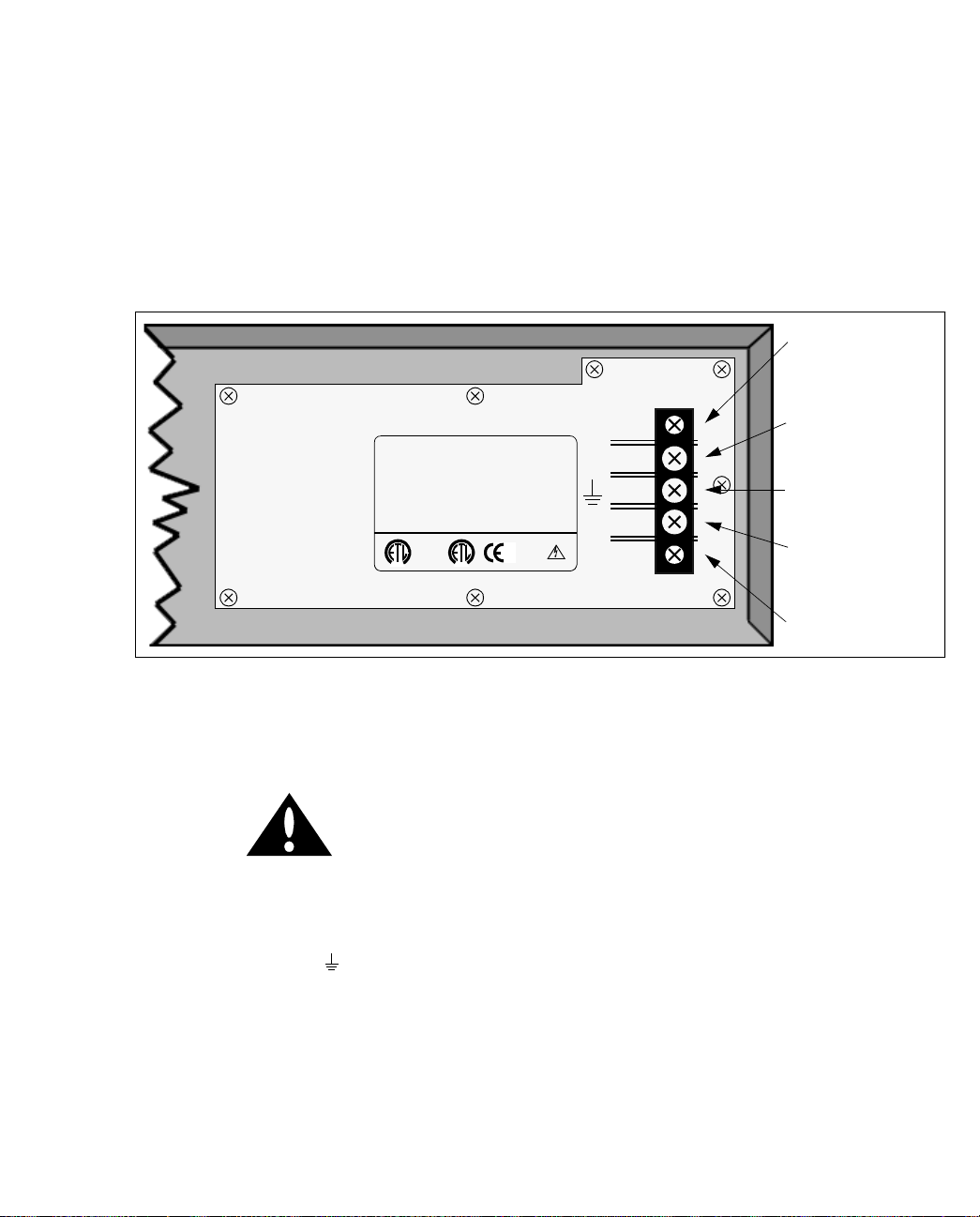
1.2.5.2 ASX-200BX -48 Volt DC Power Supply
On the back of the DC-equipped ASX-200BX, there are two three-terminal barrier terminal
strips, one for each -48 volt DC power supply, as shown in Figure 1.9. The screw terminals are
#6 screws. The -48 volt feed wires should be attached to the terminal strips using wire terminals designed to fit #6 studs. FORE Systems recommends using eith er ring terminals o r locking forked tongue terminals. Wire gauge should be AWG #16 or larger.
Retaining Screw
Positive Terminal
FORE
SYSTEMS
THIS DEVICE COMPLIES WITH P ART 15 OF THE FCC R ULES, OPERA TION
IS SUBJECT TO THE FOLLOWING TWO CONDITIONS: (1) THIS DEVICE
MAY NO T CAU SE HARMF UL INTE RFEREN CE, AND (2) THI S DEVIC E MUST
ACCEPT ANY INTERFERENCE RECEI VED, INCLUDING INTERFERENCE
THAT MA Y CA USE UNDESIRED OP ERA TION.
CONFORMS TO
ANSI / UL STD 1969
CERTIFIED TO
CAN / CSA STD
C22.2 NO. 960
®
39432
Serial #
Model # ASX-200BX DC
™
U.S. PATENT # 5,32 3, 3 89
C
®
36 - 76 VDC === (DC)
10A
MADE IN U.S.A.
+
Ground Terminal
_
Negative Terminal
Retaining Screw
Figure 1.9 -
CAUTION
Rear Panel of a DC-powered ASX-200BX
Be sure to observe polarity. Failure to do so may
cause permanent damage to the unit.
The higher potential wire should be connected to the positive (+) terminal, and the lower
potential wire to the negative (–) terminal. The chassis ground wire also should be connected
to the center terminal ( ) and connected to an earth ground.
1 - 14
ForeRunner
ATM Switch User’s Manual

Power Supply LEDs
Switch Hardware
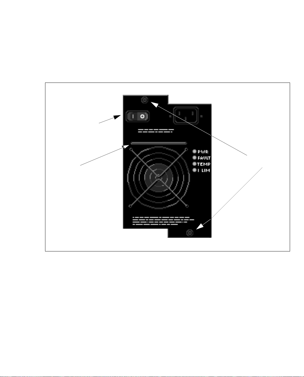
Figure 1.10 -
Front View of an ASX-200BX’s DC Power Supplies
The ASX-200BX has two power supply LEDs, one for each removable, hot-swappable power
supply. Each LED is located to the left of the power switch on the front panel for that supply as
shown in Figure 1.10. On the DC power supply for the ASX-200BX, the LED is green under
normal circumstances, indicating that the 5-volt supply coming from that particular power
supply is functioning properly.
CAUTION
If the power supply LED is red, the faulty supply
should be turned off as soon as possible, using
the single power switch which controls power to
that supply. The problem should then be
diagnosed and repaired. Please refer to Chapter
3, Hardware Maintenance Procedures, for details
about how to hot-swap a power supply in the
ASX-200BX.
A replacement DC power supply will not
NOTE
function in an AC-equipped ASX-200BX, and
vice-versa. However, no damage will be done if
this occurs.
Switch Hardware
ForeRunner
ATM Switch User’s Manual
1 - 15

Switch Hardware
1.2.5.3 ASX-1000 AC Power Supply (Model A)
The model A AC power supply for an ASX-1000 is shown in Figure 1.11.
Retention
screws
Ejection/insertion
handle
Figure 1.11 -
Model A ASX-1000 AC Power Supply
1.2.5.3.1 Power Supply LEDs
There are four status LEDs on the front panel of the model A ASX-1000 AC power supply. The
LEDs and their functions are described in Table 1.5.
1 - 16
ForeRunner
ATM Switch User’s Manual

Switch Hardware
Table 1.5 -
ASX-1000 Power Supply LED Descriptions
LED Color Meaning
Green Input voltage is OK
AC OK
extinguished No input voltage or unit has shut down
Green Backplane output is OK
DC OK
extinguished Backplane output is not present or out of range
Green Backplane standby voltage is OK
5VDC OK
extinguished Backplane standby voltage not present or out of
range
Yellow Supply is in shutdown
SHUTDOWN
extinguished Supply is operating correctly or is OFF
1.2.5.3.2 Shutdown Conditions
To av oid damaging itself or the s witch, the model B ASX-1000 A C power supply shuts itself
down under the following condition:
Overload The power supply is overloaded or the AC input is
out of specification, and the supply voluntarily shuts
down to avoid damage to the system.
Switch Hardware
The ASX-1000 CEC can not shut down the model
NOTE
A power supply. Only the power supply can
shut itself down in an overload state.
If a model A power supply goes into shutdo wn, it will remain shut down until the power
switch is turned off and turned on again (power cycle). The power switch must remain off
long enough for the SHUTDOWN LED to extinguish (this allows the capacitors to discharge).
WARNING!
A replacement AC power supply should never
be placed in a n AS X-1 00 0 that al ready con ta ins a
DC power supply, and vice-versa. If these
instructions are not heeded, there is a risk of
electrical shock, danger to personal health, and
serious damage to the equipment.
ForeRunner
ATM Switch User’s Manual
1 - 17
Switch Hardware
If the power supply needs to be replaced, please refer to Chapter 3 for hot-swap information.
1.2.5.4 ASX-1000 AC Power Supply (Model B)
The model B AC power supply for an ASX-1000 is shown in Figure 1.12.
ON/OFF Switch
Captive
Handle
fasteners
Figure 1.12 -
Model B ASX-1000 AC Power Supply
1.2.5.4.1 Power Supply LEDs
There are f our LEDs on the fr ont pa nel of the mode l B ASX-100 0 AC power supply which indicate the status of the power supply. The LEDs and their functions are described in Table 1.6:
1 - 18
ForeRunner
ATM Switch User’s Manual

Switch Hardware
Table 1.6 -
ASX-1000 Power Supply LED Descriptions
LED Color Meaning
Green Input voltage is OK
PWR OK
extinguished No input voltage or unit has shut down
Yellow Power supply has faulted
FAULT
extinguished No faults detected in power supply
Yellow Operating temperature out of range
TEMP
extinguished Running within safe temperature range
Yellow Overload condition
I LIM
extinguished Load in range
1.2.5.4.2 Shutdown Conditions
To av oid damaging itself or the s witch, the model B ASX-1000 A C power supply shuts itself
down under the following error conditions:
Input undervoltage The AC line voltage is below 87 ±5VAC RMS.
Output undervoltage Output 1 is 42 ±2 VDC o r Output 2 is below 4.5 ±0.25
VDC. Shutdown from undervoltage is defeated
during power-up period (2 seconds maximum) to
allow slow-start.
Switch Hardware
Output overvoltage The voltage at Output 1 or Output 2 is above 125%
±8% of the nominal voltage.
Overtemperature Any power semiconductor has reached 90% of its
maximum junction temper ature.
The ASX-1000 CEC can not shut down the model
NOTE
B power supply. Only the power supply can shut
down and restart itself.
If a model B power supply goes into sh utdown, i t remains turn ed off until the f ault co ndition
is rectified. At that point, the pow er supp ly restarts its elf, except in the cas e of an overvolta ge
condition.
To recover from a shutdown caused by an overvoltage state, the AC line input must be turned
off for at least one second.
ForeRunner
ATM Switch User’s Manual
1 - 19

Switch Hardware
WARNING!
If the power supply needs to be replaced, please refer to Chapter 3, Hardware Maintenance
Procedures, for hot-swap information.
A replacement AC power supply should never
be placed in a n AS X-1 00 0 that al ready con ta ins a
DC power supply, and vice-versa. If these
instructions are not heeded, there is a risk of
electrical shock, danger to personal health, and
serious damage to the equipment.
1.2.5.5 ASX-1000 -48 Volt DC Power Supply
On the front of the -48 volt ASX-1000 power supply, there are two thr ee-terminal barrier terminal strips, one for each power supply. The screw terminals are #6 screws. The -48 volt feed
wires should be attached to the terminal strips using wire terminals desig ned to fit #6 st uds.
FORE Systems recommends using either ring terminals or locking forked tongue terminal s.
Wire gauge should be AWG #12 or larger.
WARNING!
Be sure to observe polarity when attaching the
wire leads to the terminals. Failure to observe
polarity may result in injury or cause permanent
damage to the unit.
The higher potential wire should be connected to the positive (+) terminal, and the lower
potential wire to the negative (–) terminal. The chassis ground wire should be connected to the
center terminal ( ) and connected to an earth ground.
The ASX-1000 has a single power supply LED on the front panel of each -48V DC power supply module. Under normal conditions, the LED is green, indicating that the voltage supplied
to the module is above 40 volts DC. If the LED is red or is extinguished, the power supply
module should be removed and examined for defect. How ever, the LED may turn red because
the voltage being supplied to the module is insufficient. If the power su pply itself is f ound to
be defective, please refer to Chapter 3, Hardware Maintenance Procedures, for information
about how to hot-swap the failed power supply.
1 - 20
ForeRunner
ATM Switch User’s Manual

Switch Hardware
WARNING!
A replacement DC power supply should never
be placed in an ASX-1000 that already contains
an AC power supply, and vice-versa. If these
instructions are not heeded, there is a risk of
electrical shock, danger to personal health, and
serious damage to the equipment.
1.2.6 ASX-1000 Fan Tray
The ASX-1000 comes with a removable fan tray. The speed of each fan is monitored by circuitry in the CEC, and is available via SNMP. In this manner, the failure of any fan can be
detected immediately. The fan tray is hot-swappable, and the entire tray may be replaced in
the event of single or multiple fan failure. For informat ion about how to hot- swap a fan tray,
refer to Chapter 3, ”Hardware Maintenance Procedures.”
The fans in the ASX-200, the ASX-200WG, and
NOTE
the ASX-200BX are not removable.
1.2.7 ASX-1000 Temperature Sensing
In the ASX-1000, a built-in thermal temperature sensor r esides on each switch board and r ead s
out the board’s local temperature. By default, the switch control software will trigger an alarm
at 65°C and will reset the alarm when the temperature drops back down to 60°C or lower.
However, the user can configure these alarm and reset thresholds in the software on an individual board via AMI. Please refer to the ATM Management Interface Manual for more informa-
tion about configuring these thresholds. If th e tem perature of an individual switch boar d were
to reach 75°C, the switch board would shut itself down immediately.
Switch Hardware
ForeRunner
CAUTION
ATM Switch User’s Manual
This overtemperature condition is detectable by
software, and will trigger an alarm condition
which is visible through ForeView Network
Management. Upon detection of an
overtemperature condition, the ASX- 100 0 sho uld
be turned off to avoid damage to internal
components.
1 - 21

Switch Hardware
1.2.8 ASX-1000 Common Equipment Card (CEC)
The CEC provided with the ASX-1000 performs several functions. Because each SCP contains
an Ethernet port, a major function of the CEC is to provide a single, unified Ethernet port connection for all of the SCPs. The CEC is also responsible for monitoring the environmental conditions of the switch and reporting this information to the SCPs. Th e CEC reports conditions
such as malfunctioning fans, overheated power supplies, and an overheated enclosure.
Two different CECs currently exist, model A and B. Both CECs operate in exactly the same
way, and both are inserted/removed in the same way. The only difference between the model
A and model B CEC is in the front panel labelling. On the model B card, component labels are
read left to right with the CEC installed (vertically) in the switch . Also, the alarm relay contacts and alarm LEDs are labelled individually for easier identification.
1.2.8.1 CEC Front Panel
The front panel of the ASX-1000 CEC includes the following features: alarm relay contacts,
CEC status LEDs, and an Ethernet port with four LEDS. These features are illustrated in Figure 1.13 (model A) and Figure 1.14 (model B). Refer to the following subsections for detailed
descriptions of these features.
AL1 AL2
Figure 1.13 -
AL1
AL2
CEC Front Panel Status Indicators (Model A)
RX
LI
COL
POL
ETH
1 - 22
ForeRunner
ATM Switch User’s Manual

AL1
AL2
AL2 / AL1
PS1 / PS2
SW3 / SW4
SW1 / SW2
Switch Hardware
LI RX
ETH
POL COL
Figure 1.14 -
CEC Front Panel Status Indicators (Model B)
1.2.8.2 Alarm Relay Contacts
Pins 1 and 2 are the contac ts for A L1, an d pin s 3 and 4 are the c ontac ts for A L2. Al thou gh the
pins are not actually labeled on an ASX-1000 CEC, they will be referred to sequentially from
top to bottom (i.e., pin 1 is the top pin when the CEC is installed in the switch, and pin 4 is the
bottom pin).
Switch Hardware
ForeRunner
ATM Switch User’s Manual
1 - 23

Switch Hardware
Pin 1
Pin 2
Pin 3
Pin 4
Figure 1.15 - Alarm Relay Contacts for AL1 and AL2
The alarm relay contacts are normally closed when there is no power to the switch. The user
can attach alarm circuits to t hese contacts to trigger an external a larm in the case of an alarm
condition on the switch.
The user can define AL1 and AL2 as major and minor alarm indicators and can display which
condition is alarming through the use of AMI. For more information, please refer to the alarm
configuration section in the ATM Management Interface Manual.
1 - 24
ForeRunner
ATM Switch User’s Manual

Switch Hardware
Table 1.7 -
Alarm Relay Contact Status During Major and Minor Alarms
Condition Pins 1 and 2 Pins 3 and 4
Switch Powered OFF Jumped Jumped
During Boot Indeterminate Indeterminate
Normal Operation Open Open
Minor Alarm Only Jumped Open
Major Alarm Only Ope n Jumped
Major and Minor Alarms Jumped Jumped
In Table 1.7, “Jumped” indicates that the circuit
NOTE
between the indicated pins has been closed (i.e.,
an external alarm would be triggered if
connected to the pins).
1.2.8.3 CEC Status LEDs
This subsection discusses the meaning of the status LEDs on the CEC of the ASX-1000 switch.
The LEDs have been designed to provide information pertaining to the state of the switch at a
glance.
Switch Hardware
ForeRunner
AL1
AL2
Figure 1.16 -
ATM Switch User’s Manual
SW4PS2
SW2
SW1
SW3PS1
CEC Status LEDs (Model A)
1 - 25

Switch Hardware
AL2 / AL1
PS1 / PS2
SW3 / SW4
SW1 / SW2
Figure 1.17 - CEC Status LEDs (Model B)
There are eight status LEDs located on the front panel of the CEC in a 2 x 4 arrangement. On
the model A CEC, the only LEDs tha t are actually labeled are AL1 and AL2, but for th e purposes of discussion, the other LEDs will be referr ed to as labeled in Figure 1 .16. The LEDs have
been broken down into the following function groups: alarm LEDs, power supply LEDs, and
switch board LEDs.
On the model B CEC, the status LEDs are
NOTE
labelled the same from top to bottom as
discussed here (see Figure 1.17).
1.2.8.3.1 Alarm LEDs
The LEDs labeled AL1 and AL2 are alarm relay LEDs. During boot-up, AL1 and AL2 are in an
indeterminate state. During normal operation, they will be off. During a state of al arm, they
will illuminate red. By default, AL1 is the major alarm indicator for fan failure, an overtemperature condition, or a power supply failure. By default, AL2 is the minor alarm indicator for
SPA NS failure and for link failure. The user may display an d/or change these configu rations
through the use of AMI. For more information, please refer to the ATM M anagement Interface
Manual.
1 - 26
ForeRunner
ATM Switch User’s Manual

Switch Hardware
1.2.8.3.2 Power Supply LEDs
There are two power supply LEDs on the front panel of the CEC, one for each power supply.
The LEDs for the two power supplies should be illuminated yellow, indicating that the CEC is
on and that the power supply corresponding to that LED is functioning correctly. The LED for
a failed power supply will be extinguished. On an ASX-1000, power supply “1” is in the slot
labeled PS1 on the enclosure, while power supply “2” is in the slot la beled PS2 on the enclosure.
1.2.8.3.3 Switch Board LEDs
There are four switch board LEDs on the front panel of the CEC, one for each possible switch
board. These LEDs should be blinking, indicating that the switch has booted and is operating
correctly. If the SCP is removed, the LEDs may remain in a steady-on or steady-off state. Even
if the SCP has booted correctly, the LEDs will n ot illuminate if the SCP is running a software
version prior to ForeThought 3.2.0. If the switch board in the slot corresponding to the LED is
not intended for an ASX-1000 (e.g., it is an ASX-200BX boar d), or if the entir e switch boar d corresponding to that LED is removed, then that LED will be extinguished. On an ASX-1000, the
SW1 LED corresponds to switch board “1,” which is in the slot labeled 1 on the enclosure, and
so on.
1.2.8.4 Ethernet Port
The Ethernet port located on the CEC of the ASX-1000 has a standard RJ-45 female connector
and is designed to provide a single, unified Ethernet connection. It is connected via the backplane and simple Ethernet repeater to each SCP’s Ethernet port, thus eliminating the need to
attach each SCP individually. This Ethernet port has four LEDs which indicate its current status as shown in Figure 1.18. These LEDs are described in Tables 1.8 through 1.11.
COL
POL
ETH
NOTE
RX
LI
Figure 1.18 -
CEC Ethernet Port and LEDs
The Ethernet port on the model B CEC is rotated
180 degrees, but the Ethernet port LEDs are in
the same relative location as before.
Switch Hardware
ForeRunner
ATM Switch User’s Manual
1 - 27

Switch Hardware
Table 1.8 - CEC Receive (RX) LED Description
LED Color Meaning
green The Ethernet port is receiving traffic normally.
off The Ethernet port is NOT receiving traffic.
Table 1.9 - CEC Link Integrity (LI) LED Description
LED Color Meaning
green The status of the twisted pair cable connected to
the CEC Ethernet port is OK.
off The Ethernet port is NOT receiving link integrity
pulses. Check the integrity of the connection.
Table 1.10 - CEC Collision (COL) LED Description
LED Color Meaning
red An Ethernet collision has been detected on the
CEC Ethernet port.
off No Ethernet collisions have been detected.
1 - 28
Table 1.11 - CEC Polarity (POL) LED Description
LED Color Meaning
amber A reverse polarity condition has been detected on
the twisted pair cable connected to the CEC Ether-
net port. The polarity is automatically corrected,
but the amber light will remain illuminated until a
corrected twisted pair cable is inserted into the
Ethernet port.
off The polarity of the twisted pair cable connected to
the CEC Ethernet port is OK.
ForeRunner
ATM Switch User’s Manual

CHAPTER 2
This chapter contains the following information about setting up a ForeRunner ATM switch:
Section 2.1 -
•
Section 2.2 -
•
Section 2.3 -
•
Section 2.4 -
•
Section 2.5 -
•
Section 2.6 -
•
Section 2.7 -
•
Section 2.8 -
•
Section 2.9 -
•
Section 2.10 -
•
Section 2.11 -
•
Section 2.12 -
•
Introduction
Unpacking
Electrical Considerations
Rack-Mounting an ASX-200, 200W G, or 200BX
Rack-Mounting an ASX-1000
Installing the Serial Cable
Modem Configuration
Configuring IP Addresses
AMI Secur i ty
Subsequent Operation
Verifying the Installation
Product Registration Information
Switch Setup
2.1 Introduction
Before installing a ForeRunner ATM switch, th ere are several impo rtant factor s that must b e
taken into consideration, depending on the type of installation site. The following sections discuss in detail how to install a ForeRunner ATM switch and any prerequisites to the installation.
It is important to read through the ENTIRE
installation procedure before attempting to turn on
the power to the unit.
ForeRunner
NOTE
ATM Switch User’s Manual
Switch Setup
2 - 1

Switch Setup
2.2 Unpacking
Upon receipt of, and before opening your ForeRunner ATM switch, inspect the package for any
damage that may have occurred during shipping. If the package shows any signs of external
damage or rough handling, notify your carrier’s representative.
When unpacking your ForeRunner ATM switch, be sure to keep all original packing materials.
They may be needed for storing, transporting, or returning the product.
CAUTION
All products returned to FORE Systems, under
warranty, must be packed in their original
packing materials.
2.2.1 Inventorying the Unit
An inventory of the switch package shoul d be perfo rmed before supplying power to t he unit.
The ForeRunner ATM switch package should contain the follo wing:
• ForeRunner ATM switch
• ForeRunner ATM Switch User’s Manual (this manual)
• ForeRunner ATM Switch Configuration Manual
• ATM Management Interface Manual
• Power cords
• Modem serial cable
• Anti-static grounding strap
• Product registration card
• Rack-moun t kit
- 1 left rack-mount bracket
- 1 right rack-mount bracket
- 1 cable strain relief rail
- 6 Phillips-head screws
1
2
containing:
If any of the items listed above are missing or damaged, please contact FORE Systems’ Technical Support immediately.
1.
The ASX-200 an d the AS X-200WG each com e with o ne power cord. The A SX-200BX and the ASX-1000 each com e
with two power cords.
2.
The rack-mount kit is not appl icable to the ASX-200 or to the A S X-1 000. The rack-mount kit is o p tion al for the ASX-
200WG and may be purchased separately.
2 - 2
ForeRunner
ATM Switch User’s Manual

2.3 Electrical Considerations
The following items should be considered when setting up the switch:
Switch Setup
CAUTION
CAUTION
Consideration should be given to the connection
of the equipment to the supply circuit and the
effect that the overloading of circuits could have
on overcurrent protection and supply wiring.
Appropriate consideration of equipment
nameplate ratings should be used when
addressing this concern.
Reliable grounding of rack-mounted equipment
should be maintained. Particular attention
should be given to supply connections other
than direct connections to the branch (i.e., use of
power strips).
Switch Setup
ForeRunner
ATM Switch User’s Manual
2 - 3

Switch Setup
2.4 Rack-Mounting an ASX-200, 200WG, or 200BX
This section applies only to the ASX-200, ASX-
NOTE
The ASX-200, ASX-200WG, and ASX-200BX are designed to be installed as stand-alone units
placed on the desktop or as rack-mounted units. The ASX-200 chassis can be rack-mounted
without modification; however, rack-mount brackets must be attached to the ASX-200WG and
ASX-200BX before they can be installed in a rack (refer to Section 2.2.1). The following items
should be addressed when rack-mounting a switch:
200WG, and ASX-200BX. See Section 2.5 for
information about rack-mounting an ASX-1000.
WARNING!
CAUTION
CAUTION
2.4.1 Required Tools
When rack-mounting equipment, make sure that
a hazardous condition is not created due to
uneven weight distribution.
FORE Systems recommends that the maximum
operating temperature not exceed 40°C.
Consideration must be made if the switch is to be
installed in a closed or multi-unit rack assembly,
because the ambient temperature of the rack
environment may be greater than the room
ambient temperature.
Take care not to block the air ven ts of t he s witc h,
as this would compromise the amount of air flow
required for proper cooling.
Rack-mounting equipment, a cable relief strain rail, and 6 Phillips-head screws are supplied
with each switch for rack-mounting the unit. You will need to supply a Phillips screwdriver.
2 - 4
ForeRunner
ATM Switch User’s Manual
Switch Setup
WARNING!
To prevent user injury and possible damage to
equipment, FORE Systems recommends that at
least two people be present when rack-mounting
a switch.
2.4.2 Installing the Rack-mount Brackets
Steps 1 - 3 apply only to the ASX-200WG and
NOTE
To install the rack-mount brackets and cable relief strain rail, use the following procedure:
1. Carefully place the switch unit upside down on a clean, flat, sturdy work surface
with the front of the unit still facing front.
2. Using a Phillips screwdriver, remove the four feet from the bottom of the unit.
3. Each rack-mount bracket has three screws that secure the bracket to the bottom of
the unit. The holes that run along the bottom of the switch are used to secure the
bracket to the bottom of the unit. Tighten the three screws to secure the left bracket,
marked HWST0027-0001, to the left side of the unit. Tighten the three screws to
secure the right bracket, marked HWST0027-0002, to the right side of the unit.
ASX-200BX. If you are mounting an ASX-200,
move on to Step 4.
4. Once the brackets are secure, choose a rack position for the switch. The switch
ForeRunner
CAUTION
should be placed right side up in the rack with the front of the unit facing forward.
CA UTION
ATM Switch User’s Manual
When attaching the rack-mount brackets, the use
of screws other than those provided could result
in damage to the unit.
When it is mounted in the equipment rack, do
not use the switch chassis to support other
equipment. This could overload the mounting
brackets and cause damage to the unit.
Switch Setup
2 - 5

Switch Setup
5. Once the switch is mounted in the rack, you can attach the cable strain relief rail if
you wish. Line up the holes in the ra il with a s et of holes directly a bove or below
the switch rack-mount brackets, then secure the rail using the enclosed screws.
The switch is an operational ATM switch at this
NOTE
point if used with other ForeRunne r switches or
with ForeRunner ATM interface cards. However,
if other vendor equipment is conn ected, you may
have to complete an initial user configuration .
If you wish to have remote access to the switch,
NOTE
you must first install a serial cable and configure
a modem. Please refer to Section 2.6 and Section
2.7 for more information.
2 - 6
ForeRunner
ATM Switch User’s Manual

Switch Setup
2.5 Rack-Mounting an ASX-1000
The ASX-1000 switch is designed to be rack-mounted. The following items should be
addressed when rack-mounting this switch:
WARNING!
CAUTION
CAUTION
CAUTION
When rack-mounting equipment, make sure that
a hazardous condition is not created due to
uneven weight distribution.
FORE Systems recommends that the maximum
operating temperature not exceed 40°C.
Consideration must be made if the switch is to be
installed in a closed or multi-unit rack assembly,
because the ambient temperature of the rack
environment may be greater than the room
ambient temperature.
Take care not to block the air ven ts of t he swit c h,
as this would compromise the amount of air flow
required for proper cooling.
Switch Setup
Ensure that any unpopulated switch board slots
are covered with a blank panel before turning on
your ASX-1000. Operating the switch with any of
these slots left open can cause a significant
temperature rise in a very short time.
ForeRunner
ATM Switch User’s Manual
2 - 7

Switch Setup
2.5.1 Installing the ASX-1000
To install the ASX-1000 in the equipment rack, use the following procedure:
1. Choose a rack position for the ASX-1000.
WARNING!
2. Place the ASX-1000 in the rack with the front of the unit facing forward.
CAUTION
3. After mounting the enclosure, verify that the enclosure is screwed tightly to the
rack to ensure that proper grounding is maintained. Additionally, the rack should
be connected to an earth ground.
NOTE
Because of the unit’s weight, two people should
lift the unit to place it in the equipment rack.
When it is mounted in the equipment rack, do
not use the ASX-1000 chassis to support other
equipment. This could overload the mounting
brackets and cause damage to the unit.
The ASX-1000 is an operational ATM switch at
this point if used with other ForeRunner sw itches
or with ForeRunner ATM interface cards.
However, if other vendor equipment is
connected, you may have to complete an initial
user configuration.
2 - 8
NOTE
If you wish to have remote access to the switch,
you must first install a serial cable and configure
a modem. Please refer to Section 2.6 and Section
2.7 for more information.
ForeRunner
ATM Switch User’s Manual

Switch Setup
2.6 Installing the Serial Cable
Connect the serial cable (supplied with the switch) from the switch’s serial port to any tty-type
device (such as a terminal, or the serial port of a workstation or PC running a terminal emulation program).
The switch’s serial port comes configured at 9600
NOTE
When you turn on the switch, you should see the switch boot on the tty device connected to
the switch’s serial port.
NOTE
baud, 8 bits, no parity and 1 stop bit.
The switch is ready for user configuration as
soon as it is connected to a tty-type device. To
access the switch, enter asx at the prompt of the
tty device.
ForeRunner
ATM Switch User’s Manual
Switch Setup
2 - 9

Switch Setup
2.7 Modem Configuration
All ForeRunner ATM switches support modem access. This may be useful if a switch is
installed in a remote location where direct, physical access to the switch is not possible or
practical. Keep the following in mind when using a modem to access a ForeRunner AT M
switch:
• To allow the ForeRunner ATM switch to communicate with the modem, a NullModem Adapter must be installed on the factory-supplied serial cable.
•The ForeRunner ATM switch will not disconnect an ATM Management Interface
(AMI) session on loss-of-carrier; therefore, you must ensure that you have completely exited from an open AMI session before disconnecting the modem session.
The following two items apply ONLY to a
NOTE
• On an ASX-200 , do not attempt to send a <BREAK> character through the modem
to the ASX-200. A <BREAK> character may force an abnormal halt of the ASX-200.
• On an ASX-20 0, power cycling a modem wh ile it is attached to the AS X-200 may
force an abnormal halt of the switch.
ForeRunner ASX-200 ATM switch.
To allow a modem to work with a ForeRunner A TM switch, you must complete two sets of configurations. First, the speed of the serial port on the ForeRunner ATM switch must be set to
match that of the attached modem and, second, the modem parameters must be configured
correctly.
2.7.1 Serial Port Configuration for an ASX-200
The ASX-200 supports three modem speeds: 1200, 2400, and 9600 baud. To match the speed of
the modem you have installed, log in to AMI on the switch. Enter the following parameters to
change the serial port speed:
configuration rs232> speed (A|B)
The (A|B) variable indicates the port letter of the serial port that is to be modified. On a local
session on an ASX-200 , the port may be A or B. The
which the serial port will run. The default is set to 9600.
2 - 10
<speed>
<speed>
variable indicates the speed at
ForeRunner
ATM Switch User’s Manual

Switch Setup
Once the speed of the serial port has been
NOTE
altered, the speed of the attached serial device
must be altered in order to access the ASX-200
through the serial port.
The ASX-200WG, ASX-200BX, and ASX-1000
NOTE
only support a modem speed of 9600 baud.
2.7.2 Modem Parameters
You should use a H ayes-compatible modem, as the configuration parameters supplied here
are applicable to this type of modem. The following parameters should be applied to your
Hayes-compatible modem to allow it to function properly with the switch’s serial port. You
may attach a tty device to the modem to set these parameters.
Setting Comment
ATE0 Turn off Echoing
ATQ1 No Return Codes
AT&C0 Force Carrier Detect (CD) High
ForeRunner
ATM Switch User’s Manual
AT&D0 Ignore Data Terminal Ready (DTR)
AT&W Save Modem Configuration
Switch Setup
2 - 11

Switch Setup
2.8 Configuring IP Addresses
The recommended configuration for a ForeRunner ATM switch is to assign an IP address to its
network interfaces. This allows you to com municate with the switch from any workstation
connected to your ATM LAN. IP addresses must be assigned to the network interfaces in
order to perform any SNMP functions. Additionally, if you intend to connect the switch to an
Ethernet, you should assign an IP address to the switch’s Ethernet network interface.
To configure the IP addresses, log in to an AMI session on the switch. To modify the IP address
of the SCP’s IP interfaces, enter the following parameters:
On an ASX-1000, the IP address must be
NOTE
configured individually for each SCP.
configuration ip address
The
<interface>
<address>
To modify the IP subnet mask, enter the following parameters:
The
<interface>
cates the subnet mask for this IP interface.
The IP address that you assign for the switch’s ATM interface must be an address within a
subnet that is assigned to your ATM LAN. In general, the entire ATM LAN should be configured as a single IP subnet. Consequently, the ATM interfaces of all ForeRunne r switches in th e
ATM LAN should be in the same IP subnet. Consult your systems administrator for help if
you are unsure of how to do so.
variable indicates the IP address for this interface.
variable indicates the name of the IP interface to be managed. The
configuration ip mask
variable indicates the name of the IP interface. The
<interface> <address>
<interface> <mask>
<mask>
variable indi-
2 - 12
ForeRunner
ATM Switch User’s Manual

Switch Setup
2.9 AMI Security
The administrative password on your ForeRunne r ATM switch may be changed to provide
password-protected access to AMI. FORE Systems recommends that you do this to prevent
unauthorized users from accessing your ForeRunner ATM switch. This option is available in
AMI at the operation level. Be sure that you want to change the password because upon
entering the command string operation password, the user is prompted to enter a new
password immediately.
For complete information about how to assign or change the password, please refer to the
ATM Management Interface Manual.
ForeRunner
ATM Switch User’s Manual
Switch Setup
2 - 13

Switch Setup
2.10 Subsequent Operation
After its initial configura tion is complete, a ForeRunner switch DOES NOT require a terminal
for normal operation.
FORE Systems strongly recommends that you
NOTE
All further communication with your ForeRunner switch can be performed over the ATM network or over Ethernet. For example, you can access AMI using telnet.
disconnect the serial cable once you have
configured the switch and then access the switch
over the ATM network or over Ethernet.
WARNING!
NOTE
NOTE
NOTE
Once installed, before any service is performed
on the unit, the power should b e turned off and
the power cord disconnected, except when
following the hot-swap instructions in this
manual.
On an ASX-200, if you leave a terminal (or
modem) attached to the ASX-200 via the serial
port, turning off the power to the terminal (or
modem) may halt the operation of the ASX-200.
On an ASX-200, if you leave a workstation
attached to the ASX-200 via the serial port,
rebooting the workstation may halt the operation
of the ASX-200.
On an ASX-200, do not turn the power off
without first halting the ASX-200. You may halt
the ASX-200 via AMI at the operation leve l .
2 - 14
ForeRunner
ATM Switch User’s Manual

Switch Setup
2.11 Verifying the Installation
To v erify that yo ur swi tch is up and runni ng, lo g in to AMI and open a ses sion on the s wit ch.
Enter the following parameters at the localhost::> pr ompt to show the configuration of all
of the ports on an individual switch fabric:
configuration port show
2.12 Product Registration Information
After you have successfully completed the installation process, please fill out the enclosed
product registration card for your ForeRunner ATM switch, and return it to FORE Systems
immediately.
ForeRunner
ATM Switch User’s Manual
Switch Setup
2 - 15

Switch Setup
2 - 16
ForeRunner
ATM Switch User’s Manual

CHAPTER 3
Hard ware Maintenance Procedures
This chapter discusses various hardware maintenance procedures for the ForeRunner ATM
switches. Items discussed include the following :
Section 3.1
•
Section 3.2
•
Section 3.3
•
Section 3.4
•
Section 3.5
•
3.1 Network Module Replacement
3.1.1 Overview
The network modules in all ForeRunner ATM switches are hot-swappable, meaning that they
can be removed and replaced with the unit under power. Network modules should only be
hot-swapped for purposes of replacing a failed unit. Therefore, they should be re placed w ith a
network module of the same type, the same Series, and with the same number of ports. A network module’s type is the class to which the network module belongs (e.g., DS1, OC-3, E3,
TAXI, etc.).
- Network Module Replacement
- Power Supply Replacement
- Fan Tray Replacement
- Switch Control Processor Replacement
- Switch Board Replacement
If a network module is removed and replaced by a network module of another type or by a
network module with fewer ports, all configuration information for that network module’s
slot will be deleted, and the new network module will be configured with the defaults for its
type. For example, if a 4-port Series A OC-3c is replaced by a 4-port Series C OC-3c, the Series
C network module will use the same configuration of the Series A network module. Any additional configurable variables will contain OC-3c defaults. If a 4-port OC-3c is replaced by a 4port DS1, all configuration information for that slot will be deleted and the DS1 will be initialized with DS1 defaults. If a 6-port DS1 is replaced by a 2-port DS1, all configuration information for the slot will be deleted, and the new DS1 initialized with DS1 defaults. If a network
module is placed into a previously vacant slot, it will be initialized into the default state
appropriate to that type of network module.
ForeRunner
ATM Switch User’s Manual
Hardware Maintenance
Procedures
3 - 1

Hardware Maintenance Procedures
3.1.2 Multicast Mode
When hot-inserting or hot-swapping a network module, the mode in which the switch is running must also be considered. A ForeRunner 200 Series switch can operate in one of two multi-
cast modes: extended mode or non-extended mode.
• Extended mode - The added features of Series C network modules give ForeRun-
ner switches greater flexibility when choosing VCIs for multicast connections.
This flexibility provides more successful multica st (point-to-multipoin t, or PMP)
connection setups. If a switch fabric is empty or if it contains only
Series LC network modules, the switch will operate in extended mode.
• Non-extended mode - If a switch fabric contains at least one Series A or B network
module, that switch fabric will operate in non-extended (or mixed) mode.
Series A and B network modules can not operate
NOTE
NOTE
in the same switch fabric as S eries LC network
modules.
The mode in which the switch operates is
determined each time the SCP restarts. If a
switch is running in extended mode and a Series
A or B network module is hot-inserted, the
switch will not automatically revert to nonextended mode. The switch must be restarted
immediately so that it operates in non-extended
mode. If it is not restarted, all multicast
connections fail on the Series A or B network
module.
Series C or
You can display the multicast mode in which your switch is operating by using the configu-
ration board show command in the ATM Management Interface (AMI).
If a switch is running in non-extended mode,
NOTE
3 - 2
originating path 0 shou ld always exist on port 1
of each Series C network module for multicast
connection setups to succeed. Multicast
connection information for all of the ports of
Series C network modules is stored in the space
allocated for port 1 and path 0 on each Series C
network module.
ForeRunner
ATM Switch User’s Manual

Hardware Maintenance Procedures
3.1.3 Hot-swapping Network Modules
When removing or replacing network modules, use the following procedure:
WARNING!
To reduce risk to the user and to prevent damage
to equipment, it is recommended that you use
the included grounding strap when handling
this or any other component.
All AMI sessions should be terminated before
NOTE
swapping network modules of different types.
1. Label and remove all network connections from the ports on the network module.
2. Loosen the two captive fasteners on either edge of the network module using a
straight screwdriver.
3. Pull firmly but carefully on the captive fasteners, removing the network mo dule
from the switch as shown in Figure 3.1.
TX1 2X1 TX1 TX1
Loosen captive fasteners
and pull STRAIGHT out.
Figure 3.1 -
Removal of Network Modules
4. Insert the r eplacement module by sliding it into the card guides. Push firmly to seat
5. Restore the network connections from Step 1.
ForeRunner
the network module so tha t the faceplate is flush w ith the switch. Re-tigh ten the
captive fasteners.
CAUTION
To ensure safety, tighten the captive fasteners
with a straight screwdriver.
ATM Switch User’s Manual
Hardware Maintenance
Procedures
3 - 3

Hardware Maintenance Procedures
3.2 Power Supply Module Replacement
The power supplies in the ASX-200BX and the ASX-1000 are hot-swappable, meaning that
they can be removed/replaced without having to shut down the switch.
WARNING!
DO NOT attempt to replace a power supply
module without reading this section. Serious
injury to the user or damage to the equipment
may result if proper replacement procedures are
not followed.
3.2.1 ASX-200BX Power Supply Module Replacement
3.2.1.1 Replacing an ASX-200BX AC Power Supply
The procedure for hot-swapping an ASX-200BX AC power supply module is as follows:
WARNING!
NOTE
To reduce risk to the user and to prevent damage
to the equipment, it is recommended that you
use the included grounding strap when handling
this or any other component.
A replacement AC power supply will not
function in a DC-equipped ASX-200BX, and viceversa. However, no damage will result if this
occurs.
3 - 4
1. Determine which power supply is defective by either consulting ForeView to tell
which is the bad supply, or by examining the power supplies themselves. A red
LED or an extinguished LED indicates the failed supply. Power supply “1” is on
the left-hand side of the unit, and power supply “2” is on the right-hand side
(while facing the front of the unit).
ForeRunner
ATM Switch User’s Manual
Hardware Maintenance Procedures
WARNING!
Failure to perform Step 2 can result in serious
injury to the user or damage to the equipment.
2. Turn OFF the power switch on the front of the defective power supply.
3. Unplug and remove the power cord from the rear of the unit that corresponds to
the failed supply. When facing the front of the unit, power supply 1 (on the left)
corresponds to the top power cord in the rear.
4. Unscrew the two captive fasteners on the front of the unit using a straight blade
screwdriver.
5. Pull forward on the handle to remove the sliding tray.
6. Unscrew the four nuts securing the inner tray to the sliding tray.
7. Lift the inner tray from the sliding tray.
8. Place the new power supply inner tray assembly in the sliding tray and screw
down the four nuts securing the inner tray.
9. Check to see that the fuses on the new unit are of the same type and rating as the
fuses in the replaced power supply. The fuses should be 4A, 240V.
WARNING!
Failure to perform Step 10 can result in s erious
injury to the user or damage to the equipment.
10. Ensure that the power switch on the new power supply is turned OFF before
11 . Push the sliding tray back into the enclosure, being careful to align the card guides.
12. To ensur e maximum safety, and to ensure that the connectors have seated pr operly,
13. Once the new supply is completely installed, re-insert and plug in the power cord,
ForeRunner
inserting it into the enclosure.
re-tighten the captive fasteners using a straight blade screwdriver.
and turn the power switch to the ON position.
ATM Switch User’s Manual
Hardware Maintenance
Procedures
3 - 5

Hardware Maintenance Procedures
3.2.1.2 Replacing an ASX-200BX DC Power Supply
The procedure for hot-swapping an ASX-200BX DC power supply module is as follows:
WARNING!
NOTE
1. Determine which power supply is defective by either consulting ForeView or by
examining the power supplies themselves. A red LED or an extinguished LED
indicates the failed supply. Power supply “1” is on the left-hand side of the unit,
and power supply “2” is on the right-hand side (while facing the front of the unit).
WARNING!
To reduce risk to the user and to prevent damage
to the equipment, it is recommended that you
use the included grounding strap when handling
this or any other component.
A replacement DC power supply will not
function in an AC-equipped ASX-200BX, and
vice-versa. However, no damage will result if
this occurs.
Failure to perform Steps 2 or 3 can result in
serious injury to the user or damage to the
equipment.
3 - 6
2. Turn OFF the power switch on the front of the failed power supply. W a it for 10 seconds before moving on to Step 3.
3. Shut off DC power to the feed wires of the failed supply. T ypically, each ASX-200BX
resides in its own circuit on a Br eaker Interf ace Panel (BIP). Turning off the top circuit breaker on the BIP will remove DC power to the feed wires.
4. On the rear of the unit, remove the pr otective plastic cover fro m the terminal block,
exposing the DC feed wires.
5. Remove the feed wires from the terminal corresponding to the failed supply. The
terminal strip on the right side (while facing the rear of the unit) corresponds with
power supply 1 (on the left side while facing the front of the unit).
6. Unscrew the two captive fasteners on the front of the failed supply using a straight
blade screwdriver.
ForeRunner
ATM Switch User’s Manual
Hardware Maintenance Procedures
7. Pull forward on the handle to remove the sliding tray.
8. Unscrew the four nuts securing the inner tray to the sliding tray, then lift the inner
tray from the sliding tray.
9. Place the new power supply inner tray assembly in the sliding tray and screw
down the four nuts securing the inner tray.
WARNING!
Failure to perform Step 10 can result in s erious
injury to the user or damage to the equipment.
10. Ensure that the power switch on the new power supply is turned OFF before
inserting it into the enclosure.
11 . Push the sliding tray back into the enclosure, being careful to align the card guides.
12. To ensur e maximum safety, and to ensure that the connectors have seated pr operly,
re-tighten the two captive fasteners using a straight blade screwdriver.
WARNING!
Be sure to observe polarity in the followi ng step.
Failure to observe polarity may cause permanent
damage to the unit and may cause in jury to the
user.
13. Once completely installed, reconnect the feed wires to the terminal strip on the rear
of the unit. Ensure that #16 AWG or larger wire is used for the DC feed wires. The
screw terminals are #6 scr ews. The 48-volt feed wir es should be attached to the terminal strips using wire terminals designed to fit #6 studs. FORE Systems
recommends the use of either ring terminals or locking forked tongue terminals.
The higher potential wire should be connected to the positive (+) terminal, and the lower
potential wire to the negative (-) terminal. A third, chassis ground wire should also be connected to the center terminal ( ) and connected to an earth ground.
14. Once the feed wires have been connected, replace the protective cover on the terminal block.
15. Return DC power to the feed wires coming into the supply by turning on the to p
breaker on the BIP.
16. Turn the circuit breaker switch on the front of the power supply to ON (up).
ForeRunner
ATM Switch User’s Manual
Hardware Maintenance
Procedures
3 - 7

Hardware Maintenance Procedures
3.2.2 ASX-1000 Power Supply Module Replacement
3.2.2.1 Replacing an ASX-1000 AC Power Supply (Model A)
A model A AC power supply module for an ASX-1000 is shown in Figure 3.2.
3 - 8
Retention
screws
Figure 3.2 -
Ejection/insertion
handle
Model A ASX-1000 AC Power Supply
ForeRunner
ATM Switch User’s Manual

Hardware Maintenance Procedures
The procedure for hot-swapping a model A ASX-1000 AC power sup p ly is as follows:
WARNING!
WARNING!
1. Determine which power supply is defective by either consulting ForeView to tell
which is the bad supply or by examining the power supplies themselv es. A red
LED or an extinguished LED indicates the failed supply. On an ASX-1000, power
supply “1” is in the slot labeled PS1 on the chassis, while power supply “2” is in
the slot labeled PS2 on the chassis.
WARNING!
A replacement DC power supply should never
be placed in an ASX-1000 that already contains
an AC power supply, and vice-versa. If these
instructions are not heeded, there is a risk of
electrical shock, danger to personal health, and
serious damage to the equipment.
It is highly recommended that you use the
included grounding strap when handling this or
any other compon ent.
Failure to perform Step 2 can result in serious
injury to the user or damage to the equipment.
2. Turn OFF the power switch on the front of the defective power supply. Wait for the
3. Unplug and remove the power cord from the failed supply.
4. Unscrew the four retaining screws with a 3/32-inc h Allen wrench and pull f or-
5. Remove the defective supply and prepare to install the new one.
ForeRunner
yellow SHUTDOWN LED to extinguish before moving to Step 3.
ward on the handle located below the power cord.
ATM Switch User’s Manual
Hardware Maintenance
Procedures
3 - 9

Hardware Maintenance Procedures
WARNING!
Failure to perform Steps 6 or 7 can result in
serious injury to the user or damage to the
equipment.
6. Ensure that the power switch on the new power supply is turned OFF before
inserting it into the enclosure.
7. Ensure that the fuses on the new unit are rated at 12.5A, 250V.
8. Carefully align the guide rails on the new AC power supply in the slot.
9. Push on the center of the front panel of the power supply to sl ide it back int o the
enclosure.
10. To ensure maximum safety and to ensure that the connectors have been seated
properly, re-tighten the four retaining screws using a 3/32-inch Allen wrench.
11. Reconnect and plug in the power cord to the new power supply.
12. Turn the power switch on the new supply to the ON position.
3 - 10
ForeRunner
ATM Switch User’s Manual

Hardware Maintenance Procedures
3.2.2.2 Replacing an ASX-1000 AC Power Supply (Model B)
A model B AC power supply module for an ASX-1000 is shown in Figure 3.3.
ON/OFF Switch
Handle
Captive
fasteners
ForeRunner
Figure 3.3 -
ATM Switch User’s Manual
Model B ASX-1000 AC Power Supply
Hardware Maintenance
Procedures
3 - 11

Hardware Maintenance Procedures
The procedure for replacing a model B ASX-1000 AC power supply module is as follows:
WARNING!
WARNING!
1. Determine which power supply is defective by either consulting ForeView to tell
which is the bad supply or by examining the power supplies themselves. An extinguished “PWR OK” LED or an illuminated “FAULT” LED indicates the failed
supply. On an ASX-1000, power supply “1” is in the slot labeled PS1 on the chassis
(top), while power supply “2” is in the slot labeled PS2 on the cha ssis (bottom).
WARNING!
A replacement DC power supply should never
be placed in an ASX-1000 that already contains
an AC power supply, and vice-versa. If these
instructions are not heeded, there is a risk of
electrical shock, danger to personal health, and
serious damage to the equipment.
It is highly recommended that you use the
included grounding strap when handling this or
any other compon ent.
Failure to perform Step 2 can result in serious
injury to the user or damage to the equipment.
3 - 12
2. Turn OFF the power switch on the front of the defective power supply. W ait at least
one (1) second after turning off the power before moving on to the next step.
3. Disconnect the AC line from the front of the defective power supply.
4. Unscrew the two captive fasteners (one on the upper, left corner of the faceplate
and one on the lower, right corner of the faceplate, see Figure 3.3) using a straight
blade screwdriver.
5. Pull forward on the power supply’s handle (located below the power switch and
AC plug) to remove it from the chassis.
6. Set the failed supply aside and prepare to install the new one.
ForeRunner
ATM Switch User’s Manual

Hardware Maintenance Procedures
WARNING!
Failure to perform Steps 7 or 8 can result in
serious injury to the user or damage to the
equipment.
7. Ensure that the power switch on the new AC power supply is turned OFF before
inserting the supply into the metal enclosure.
8. Check to see that the fuses on the new unit are rated at 15A, 250V.
9. Set the supply on the guide rails in the enclosure so that th e supply is properly
aligned in the slot. Position the supply so that the rear connectors are on top.
10. Once the rails are properly aligned, push on the handle on the front of the supply
to slide it back into the chassis. Press firmly to ensure that the connectors on the
rear of the supply have mated with those on the backplane.
1 1. To ensure maximum safety and to ensure that the connectors have mated pr operly,
tighten the two captive fasteners on the front of the supply using a straight blade
screwdriver.
12. Once completely installed, you may reconnect the AC line and turn the power
switch to the ON position.
13. After a second or two, the PWR OK LED on each supp ly illuminates green, indicating that the supply is functio ning properly.
ForeRunner
ATM Switch User’s Manual
Hardware Maintenance
Procedures
3 - 13

Hardware Maintenance Procedures
3.2.2.3 Replacing an ASX-1000 DC Power Supply
The DC power supply module for an ASX-1000 is shown in Figure 3.4.
Retaining
screws
Power supply
LED
Circuit breaker
switch
3 - 14
Positiv e Terminal
Ground Terminal
Negative Terminal
Retaining
screws
Figure 3.4 -
Ejection/insertion
handle
ASX-1000 DC Power Supply
ForeRunner
ATM Switch User’s Manual

Hardware Maintenance Procedures
The procedure for hot-swapping an ASX-1000 DC power supply module is as follows:
WARNING!
WARNING!
1. Determine which power supply is defective either by consulting ForeView or by
examining the power supplies themselves. A red LED or an extinguished LED
indicates the failed supply. Power supply “1” is in the slot labeled PS1 on the chassis, and power supply “2” is in the slot labeled PS2 on the chassis.
WARNING!
To reduce risk to the user and to prevent damage
to the equipment, it is recommended that you
use the included grounding strap when handling
this or any other component.
A replacement DC power supply should never
be placed in an ASX-1000 that already contains
an AC power supply, and vice-versa. If these
instructions are not heeded, there is a risk of
electrical shock, danger to personal health, and
serious damage to the equipment.
Failure to perform Steps 2 or 3 can result in
serious injury to the user or damage to the
equipment.
2. Turn OFF (down) the circuit breaker switch on the failed power supply.
3. Shut off DC power to the feed wires of the failed supply. Typically, each ASX-1000
4. Remove the pro tective plastic cover from the terminal block, exposing the DC feed
5. Remove the feed wires from the front of the unit.
6. Unscrew the four retaining screws that secure the power supply i n the chassis
7. Pull forward on the ejection/insertion handle to remove the failed supply.
ForeRunner
resides in its own circuit on a Br eaker Interf ace Panel (BIP). Turning off the top circuit breaker on the BIP removes DC power to the feed wires.
wires.
using a 3/32-inch Allen wrench.
ATM Switch User’s Manual
Hardware Maintenance
Procedures
3 - 15

Hardware Maintenance Procedures
WARNING!
8. Ensure that the circuit breaker switch on the new power supply is turned OFF
(down) before inserting it into the enclosure.
9. Carefully align the guide rails on the new DC power supply in the slot, then push
on the ejection/insertion handle to slide it into the enclosure.
10. To ensure maximum safety and to ensure that the connectors have been seated
properly, re-tighten the four retaining screws using a 3/32-inch Allen wrench.
11. Once completely installed, reconnect the feed wires to the terminal strip on the
front of the unit. Ensure that the DC feed wires are #12 AWG or larger. The screw
terminals are #6 screws. The 48-volt feed wires should be attached to the terminal
strips using wire terminals designed to fit #6 studs. FORE Systems recommends
the use of either ring terminals or locking forked tongue terminals.
CAUTION
Failure to perform Step 8 can result in serious
injury to the user or damage to the equipment.
Be sure to observe polarity in the followi ng step.
Failure to observe polarity may cause permanent
damage to the unit and may cause in jury to the
user.
The higher potential wire should be connected to the positive (+) terminal, and the lower
potential wire to the negative (-) terminal. A third, chassis ground wire should also be connected to the center terminal ( ) and connected to an earth ground.
12. Once the feed wires have been connected, replace the protective cover on the terminal block.
13. Return DC power to the feed wires coming into the supply by turning on the top
breaker on the BIP.
14. Turn the circuit breaker switch on the front of the new supply to the ON (up)
position.
3 - 16
ForeRunner
ATM Switch User’s Manual

Hardware Maintenance Procedures
3.3 ASX-1000 Fan Tray Replacement
The ASX-1000 has a removable fan tray with large fans that cool th e switch hardware and
power supply modules. Located at the base of the upright unit, the fan tray is removable from
the front of the unit and is hot-swappable, meaning that it can be replaced with the ASX-1000
under power. The procedure for replacing a fan tray is as follows:
WARNING!
1. Remove the four retaining screws at the top of the fan tray with a 3/32-inch Allen
wrench.
2. Remove the fan tray by pulling it away from the switch unit.
3. Set the old fan tray aside and place the new fan tra y in front of the vacant slot in
the ASX-1000.
4. Insert a new fan tray in the slot and slide it all the way into the chassis. Seat the
connectors by pressing firmly on the unit (this will apply power to the fan tra y).
5. Once seated, replace the four screws removed in Step 1 above. This will properly
secure the unit in the chassis.
CAUTION
It is highly recommended that you use the
included grounding strap when handling this, or
any other compon ent.
Do not run the unit for any great length of tim e
without the fan tray installed or the unit will
shut itself down because of an overtemperature
condition.
ForeRunner
ATM Switch User’s Manual
Hardware Maintenance
Procedures
3 - 17

Hardware Maintenance Procedures
3.4 Switch Control Processor Replacement
The following procedure explains how to remove an i960 switch control processor (SCP) from
a switch fabric and install a new SCP.
WARNING!
CAUTION
1. If replacing a CF-based SCP, or earlier, turn the power switch on any installed
power supplies to the OFF position; unplug and remove all power cords.
2. Loosen the captive fastener s on either edge of the SCP using a straight scr ewdriver.
3. Pull firmly and carefully on the two captive fasteners, removing the SCP from the
switch fabric as shown in Figure 3.5.
It is highly recommended that you use the
included grounding strap when handling this or
any other compon ent.
Do not attempt to remove or replace an SCP
without first removing all connections to the SCP
(i.e., serial or Ethernet connections).
Only HA-based SCPs are hot-swappable. If yo u
are replacing an earlier model SCP, you must
power down the switch before starting this
procedure.
3 - 18
Loosen captive fasteners
and pull STRAIGHT out.
Figure 3.5 -
Removal of an SCP
ForeRunner
ATM Switch User’s Manual

4. Set the old SCP aside.
Hardware Maintenance Procedures
CAUTION
Take care to properly align the SCP in the card
guides in the following step.
5. Insert the new SCP into the switch fabric by sliding it into the card guides.
6. Push firmly to seat the SCP so that its faceplate is flush with the front panel of the
switch board.
7. Re-tighten the captive fasteners with a straight screwdriver to ensure the SCP is
secure.
8. Plug any necessary power cords into the switch, then plug into an approved outlet.
9. Turn power switches on any installed power supplies to the ON position.
Once the SCP has been installed and the switch boots, the PVCs will be re-established provided that none of the network modules were replaced after the SCP was removed and provided that all of these steps have been performed properly.
ForeRunner
ATM Switch User’s Manual
Hardware Maintenance
Procedures
3 - 19

Hardware Maintenance Procedures
3.5 Switch Board Replacement
The switch boards in the A SX-1000 are hot-sw appabl e, me an in g th at t he y ca n be removed and
replaced with the chassis under power. The proper procedure for hot-swapping a switch
board is as follows:
WARNING!
CAUTION
NOTE
NOTE
It is highly recommended that you use the
included grounding strap when handling this, or
any other compon ent.
Ensure that any unpopulated switch board slots
are covered with a blank panel before turning on
your ASX-1000. Operating the switch with any of
these slots left open can cause a significant
temperature rise in a very short time.
As a precaution, it is recommended that you
back up your CDB before performing this
process. Instructions for backing up your CDB
can be found in the ATM Management Interface
Manual.
Replace a switch board ONLY with another
switch board of the same type (i.e., an ASX-1000
switch board with an ASX-1000 switch board).
3 - 20
NOTE
To ensure that the switch will work with the
previously established network configuration,
the relative position of the network modules
must not change when yo u transfer them to the
new fabric. For example, an OC-3c network
module that is removed from slot A of the old
switch fabric must be installed in slot A of the
new switch fabric. Therefore, it is recommended
that you label all network connections and
network modules be fore removing them.
ForeRunner
ATM Switch User’s Manual

Hardware Maintenance Procedures
To maintain your CDB, the SCP must be
NOTE
removed before
the network modules are
removed and it must be installed in the new
fabric after
the network modules have been
installed.
1. Log out of all open AMI sessions on the switch board that is to be replaced.
2. Remove the SCP from the old switch board using the instructions found in Section
3.4, Switch Control Processor Replacement. Place the SCP on a clean, static-free
work area.
3. Label and remove all fibers or coaxial cables connected to the ports on the switch
board that is to be replaced. Then label and remove all network modules from the
old switch board using the instructions found in Section 3.1, Network Module
Replacement. Place the network modules on a clean, static-free work area.
4. Unscrew the retaining screws at the top and bottom of the switch board with a 3/
32-inch Allen wrench. On an ASX-1000, press the top black locking tab up towards
the top and bottom black locking tab down towards the bottom of the chassis until
they are parallel with the front panel of the switch.
5. Using the tabs as a handle, pull the switch board out of the chassis.
CAUTION
Make sure the replacement board is properly
aligned in the slot in the next step.
6. Carefully
slide the replacement board into the chassis using enough force to ensure
that the connectors on the board mate with the connectors in the chassis.
7. Be sure to align the holes properly and screw the board into the chassis using the
screws at the top and bottom of the board. Tighten until snug, but do not
overtighten.
8. Re-install the network modules usin g the instructions found in Se ction 3.1, Network Module Replacement. Reconnect all fibers or coaxial cables to the ports.
9. Re-install the SCP using the instructions found in Section 3.4, Switch Control Processor Replacement.
Once the SCP has been installed and the sy stem reboots, the PVCs wi ll be re-established if al l
of the steps have been performed correctly and in the proper sequence.
ForeRunner
ATM Switch User’s Manual
Hardware Maintenance
Procedures
3 - 21

Hardware Maintenance Procedures
3 - 22
ForeRunner
ATM Switch User’s Manual

CHAPTER 4
This chapter details the steps necessary to upgrade the ForeThought software on your ForeRun-
ner ATM switch. Some instructions in this chapter apply only when upgrading certain
switches in certain situations, and you may or may not have to go through every section. Read
the following list to better understand how the instructions are ordered before moving on:
Section 4.1 -
•
Section 4.2 -
•
Section 4.3 -
•
Section 4.4 -
•
Section 4.5 -
•
Section 4.6 -
•
Section 4.7 -
•
Obtaining the Software Upgrade File
Requirements for Upgrading an ASX -2 00WG
Performing the Software Upgrade
Loading the New Software Image onto the ASX-200
Changing between Multiple Versions of Software
Booting and Upgrading with Mini Loader
Using bootp to Download Software to the Switch
Software Upgrade Instructions
Software Upgrade
Instructions
CAUTION
NOTE
NOTE
As a precaution, it is recommended that you back up
your CDB before beginning the upgrade process. For
more information, see the ATM Management Interface
Manual.
Each of the SCPs on an ASX-1000 must be upgraded
individually.
The operation upgrade command can be issued
one of two ways, depending on how TFTP is
configured on the UNIX workstation that holds the
upgrade file. For more information about usi ng this
command, see Section 4.3 and Section 4.7.4.
ForeRunner
ATM Switch User’s Manual
4 - 1

Software Upgrade Instructions
4.1 Obtaining the Software Upgrade File
Before beginning the upgrade process, you will need the upgrade file from FORE Systems.
This file can be obtained via FTP or diskette. To obtain the file via FTP, you must have FTP
access. To obtain the file from diskette, you will need the distribution disk ettes from FORE
Systems.
You will a lso need a UNIX workstation wit h at least 5 Mbytes of free disk space (12 Mbytes if
you are upgrading an ASX-200). If you are upgrading from the distribution diskettes, the
UNIX workstation must also be equipped with a floppy drive. The UNIX workstation must be
connected (via ATM or Ethernet) to the SCP being upgraded.
4.1.1 Obtaining the Software Upgrade File via FTP
The software upgrade can be retrieved from FORE S ystems via anonymous FTP using the following procedure. First, FTP t o ftp.fore.com. and log in as anonymous. Enter your full e-
mail address (e.g., jdoe@somewhere.com) when you are prompted for a password.
For security reasons, your password is not
NOTE
echoed.
Once you connect to FORE’s FTP site (you will see the ftp> prompt), you must change to the
/priv/release/sunny directory. This directory contains the ForeThought software upgrade
files and the .readme files which contain important information about the software release.
Because the contents of this directory cannot be
NOTE
The .readme files can be retrieved as ASCII text. However, before you retrieve the software
files, you must switch the transfer mode to binary.
The following script is an example o f how you might retrieve the software and .readme files.
User input is shown in bold courier font.
4 - 2
listed, please contact FORE Technical Support to
obtain the latest list of file names. If you are
upgrading an ASX-200WG, you will need both
the switch software upgrade and the Mini
Loader software.
ForeRunner
ATM Switch User’s Manual

Software Upgrade Instructions
server-jdoe:52=> ftp ftp.fore.com
Connected to ftp.fore.com.
220 ftp.fore.com FTP server (Version wu-2.4(4) Tue Apr 11 13:53:34 EDT 1995) ready.
Name (ftp.fore.com:jdoe): anonymous
331 Guest login ok, send your complete e-mail address as password.
Password: TYPE YOUR FULL E-MAIL ADDRESS HERE <ENTER>
230230- WELCOME to the FORE Systems FTP Server!
230230- We are currently making many changes to the server to make it easier
230- for you use and search for the files that you are looking for.
230- Announcements regarding these changes will be posted here as they
230- are completed.
230230- If you have any problems finding the files that you are looking for,
230- you can contact FORE Systems Technical Support by phone or send email
230- to support@fore.com.
230230- Abuse of any FORE Systems Technical Services system is grounds for the
230- immediate removal of all access.
230230230 Guest login ok, access restrictions apply.
ftp> cd /priv/release/sunny <ENTER>
250 CWD command successful.
ftp> get asx-scp_4.1.0_1.3.readme <ENTER>
200 PORT command successful.
150 Opening ASCII mode data connection for asx-scp_4.1.0_1.3.readme (51578 bytes).
226 Transfer complete.
local: asx-scp_4.1.0_1.3.readme remote: asx-scp_4.1.0_1.3.readme
51578 bytes received in 1 seconds (50 Kbytes/s)
ftp> binary <ENTER>
200 Type set to I.
ftp> get asx-scp_4.1.0_1.3.Z <ENTER>
200 PORT command successful.
150 Opening BINARY mode data connection for asx-scp_4.1.0_1.3.Z (8147013 bytes).
226 Transfer complete.
local: asx-scp_4.1.0_1.3.Z remote: asx-scp_4.1.0_1.3.Z
8147013 bytes received in 2.3e+02 seconds (35 Kbytes/s)
ftp> quit <ENTER>
221 Goodbye.
Software Upgrade
Instructions
ForeRunner
ATM Switch User’s Manual
4 - 3

Software Upgrade Instructions
If you have retrieved a software file with a .Z extension, then you need to uncompress the file
using the following command:
uncompress <filename>
where
example, using the software file from the previous example:
If you have difficulty retrieving the files or if you have any other questions regarding the FTP
site, please contact FORE Systems’ Technical Support by sending e-mail to support@fore.com
or by calling 800-671-FORE.
Once you have successfully retrieved the software upgrade file via FTP, follow the instructions
in Section 4.3.
<filename>
represents the full name of the upgrade file you have retrieved. For
uncompress asx-scp_4.1.0_1.3.Z
If you have retrieved a software file with a .tar
NOTE
extension, do NOT untar it. The operation
upgrade command in the ATM Management
Interface (AMI) will expect the upgrade file to be
in tarfile format.
4.1.2 Obtaining the Software Upgrade File via Diskette
Using the FORE System s distribution diskettes, the upgrade software must be install ed on a
workstation attached (via Ethernet or ATM) to the SCP being upgraded. The first disk contains
a part of the distribution software, as well as a script that extracts the remaining software from
the rest of the disks and builds the upgrade dis tribution on the workstation. The first disk can
be extracted using the tar command:
tar -xvf <device>
where
ejected from the floppy drive. On a SunOS system, the following command will eject a disk :
where
there may be a different command for ejecting a floppy disk or there may be a manual eject
button. If there is a manual e ject button, eject the disk and proceed. If there is a UNIX command for ejecting the floppy, use that command to eject the floppy and proceed.
4 - 4
<device>
<device>
is the block device name of the floppy drive. This disk should then be
eject <device>
is the block device name of the floppy drive. On other operating systems,
ForeRunner
ATM Switch User’s Manual

Software Upgrade Instructions
At this point, two files should have been created: fore_extract and ASX-200BX_<version>
(where <version> is the new software version). This file will be named ASX-
200_<version> if you are using the distribution diskettes for an ASX-
200. The fore_extract file is the script that will extract the files from the other floppies. If
there is a command to eject a floppy on your system, set the following environment variable
so the fore_extract script can properly eject the floppies:
setenv FORE_EJECT <eject_command> (for csh)
or
FORE_EJECT<=eject_command>;export FORE_EJECT (for sh)
On a Sun running SunOS 4.1.x, set the following environment variable so the fore_extract
script can properly eject the floppies:
setenv FORE_EJECT eject
Execute the fore_extract script with the following command:
./fore_extract <device>
Software Upgrade
Instructions
Once again,
<device>
is the block device name of the floppy drive. You will be asked to
insert the remaining disks in sequence. If these steps are performed correctly, something similar to the following should appear on the screen:
filename: ASX-200BX_<
directory: <directory from which it was extracted>
The fore_extract script will create a file called ASX-200BX_
200_
<version>
, depending on the switch being upgraded) in the current directory. This is
version>
<version>
(or ASX-
the file that the SCP will use to upgrade its software. You will need to provide this filename
and path later during the upgrade process.
ForeRunner
ATM Switch User’s Manual
4 - 5

Software Upgrade Instructions
4.2 Requirements for Upgrading an ASX-200WG
This section applies only to an ASX-200WG
NOTE
If you are using a ForeRunner ASX-200WG, certain steps are required before performing the
software upgrade. The FLASH on an ASX-2 00WG is no t large enough to hol d more than one
copy of switch software at a time. Therefore, the following steps are necessary:
1. You should have already downloaded the software upgrade file to a UNIX workstation. If not, see Section 4.1.
2. Download the Mini Loader softwar e to the same UNIX workstation as you did the
upgrade file (see Section 4.2.1).
3. Delete everything but the current version of switch software from FLASH (see Section 4.2.2).
4. Upgrade your switch to Mini Loader (see Section 4.2.3).
5. Delete the active version of switch software from FLASH (see Section 4.2.4).
6. Perform the software upgrade (see Section 4.3).
upgrade. If you are upgrading an ASX-200BX or
an ASX-1000, proceed to Section 4.3. If you are
upgrading an ASX-200, proceed to Section 4.4.
4.2.1 Downloading the Mini Loader Software
You can obtain the Mini Loader software just as you obtained the software upgrade file, via
FTP or distribution diskettes. If you are obtaining the Mini Loader software via FTP, follow the
same instructions as in Section 4.1.1, but substitute the Mini Loader filename for the upgrade
filename. If you are obtaining the Mini Loader software from the FORE Systems distribution
diskettes, follow the same instructions as in Section 4.1.2.
4 - 6
ForeRunner
ATM Switch User’s Manual

Software Upgrade Instructions
4.2.2 Emptying the FLASH
Once you have obtained the software upgrade file and the Mini Loader software, you must
open an AMI session and delete everything except your current version of switch software
from the FLASH of the switch being upgraded.
For example, if you are running FT 4.1.0 and you still have an ima ge for FT 3.4.3 in FLASH,
you must delete the foreos.exe f ile from the ft343.x directory, then delete the ft343.x
directory itself. Enter something similar to the following at the localhost::> prompt:
operation flash delete ft343.x/foreos.exe
operation flash delete ft343.x
If there are any other files or dir ectories stored in FLASH, EXCEPT the active version of switch
software, you should delete them according to the above conventions.
CAUTION
Make sure you do not delete the active ver sion o f
switch software from FLASH until you reach
Section 4.2.4.
Software Upgrade
Instructions
4.2.3 Upgrading the Switch to Mini Loader
Once you have deleted any extra items from FLASH, you must upgra de the softwa re on your
switch to Mini Loader. Before initiating the upgrade, you must ensure that the Mini Loader
software resides in the /tftpboot directory on the UNIX workstation to which you downloaded the software. See Section 4.7.4 for instructions on how to create the /tftpboot directory (if necessary) and how to move the Mini Loader software into that directory.
Once the Mini Loader software is in the /tftpboot directory, enter the following parameters
at the localhost::> prompt:
operation upgrade <remotehost>:<full path to remotefile>
In the abov e example , you mu st enter the IP ad dress of th e UNIX wo rkstatio n to whic h you
downloaded Mini Loader in place of
name in place of
at the localhost::> prompt:
ForeRunner
ATM Switch User’s Manual
<full path to remotefile>
operation upgrade 204.95.89.91:foreworks-loader.tar
<remotehost>
. You must enter the Mini Loader file-
. Enter something similar to t he follow ing
4 - 7

Software Upgrade Instructions
The switch will init iate a TFTP session with the host work statio n, a nd yo u wil l see someth in g
similar to the following:
Getting /foreworks-loader.tar from 204.95.89.91...
######################################################################################
############################################################
If the upgrade is successful, the series of # symbols will be fol lowed by “
was successful.
Reboot the switch [y]?
” You will then be prompted to reboot the switch
switch upgrade
Type n and press <ENTER> at the prompt.
If the upgrade fails for some reason, try again. First, however, delete the file from FLASH
UPGRADE
called
that will have been created (but is not complete) during the failed upgrade.
If you have problems with the upgrade to Mini Loader, please contact FORE Systems’ Technical Support.
After a successful upgrade, CURRENT points to
NOTE
an image for Mini Loader in FLASH. If
something causes your switch to reboot, it will
do so using the Mini Loader software.
4.2.4 Deleting the Active Switch Software
Now that Mini Loader is safely loaded on your switch, you can delete the active version of
switch software from FLASH. Deleting thi s file and the directory in which it resides will no t
affect the operation of your switch. The switch software will continue to run in active memory
after its image is deleted from FLASH. Enter something similar to the following at the
host::>
prompt:
local-
operation flash delete ft400.x/foreos.exe
operation flash delete ft400.x
These commands will delete the im age of the active v ersion of switch software in FLASH, a s
well as the directory in which it is contained. The para meter
ft400.x
will vary depending on
which version of switch software you are currently using.
At this point, you should upgrade your switch to ForeThought 4.1.x (see Section 4.3).
4 - 8
ForeRunner
ATM Switch User’s Manual

Software Upgrade Instructions
4.3 Performing the Software Upgrade
The software upgrade is performed with the operation upgrade command in AMI. The
underlying file transfer mechanism used in the upgrade is TFTP. TFTP can run in “secure” or
“unsecure” mode, and it is assumed that your TFTP server is running in secure mode. Therefore, if TFTP is to run properly between, the file(s) being transferred must reside in the /tft-
pboot directory on the source machine (see Section 4.7.4 for more information).
To perform an upgrade, the switch initiates a TFTP session with the specified host, which
searches for the file requested. The host, which is running TFTP, looks for the file in /tftp-
boot. The TFTP process on the server automatically appends “/tftpboot” to the path or
filename specified by the client.
For example, issuing operation upgrade 169.144.3.54:asx-scp_4.1.0_1.3 will
cause the TFTP server to locate and transfer the file /tftpboot/asx-scp_4.1.0_1.3. For
this reason, it is imperative that you place the upgrade file in the /tftpboot directory on the
workstation to which you downloaded or extracted the file. If this directory does not already
exist, it is likely that T FTP is not running on the workstation. See S ection 4.7.4 for ins tructions
on setting up a TFTP server and placing the upgrade file in the /tftpboot directory.
Once you have verified your TFTP server and placed the software upgrade file, you need to
invoke the upgrade process on the SCP. Log in to AMI and enter the following parameters at
the localhost::> prompt:
operation upgrade ?
Software Upgrade
Instructions
This will display the specific parameters that you need to enter as follows:
upgrade
In the
<remotehost>
which holds the upgrade file. In th e
filename of the upgrade file.
NOTE
ForeRunner
ATM Switch User’s Manual
<remotehost>:<full path to remotefile>
field, enter the remote machine name or IP address of the workstation
<full path to remotefile>
If you obtained the upgrade file via FTP,
path to remotefile>
uncompressed file. If you obtained the file from
diskette,
name printed during extraction.
<full path to remotefile>
field, enter ONLY the
is the name of the
<full
is the
4 - 9

Software Upgrade Instructions
For example, if you used FTP, you would enter something similar to the following:
operation upgrade 169.144.3.54:asx-scp_4.1.0_1.3
If you extracted the file from diskette, you would enter something similar to the following:
operation upgrade 169.144.3.54:ASX-200BX_4.1.0_1.3
In either case, you should receive messages similar to the following:
Received 688128 bytes in 5.3 seconds
upgrade successful
Reboot the switch[y]?
You have an important decision to make now. At
NOTE
this point, the boot pointer will have the new
software’s filename in it. A reboot will lo ad the
new version of software to FLASH, and the
switch will be running the upgraded version
when it comes up. If you wish, however, you can
still run the old version of software. If you want
to use the old version and change to the new
version at a later time, enter n at the reboot
prompt and follow the instructions in Section 4.5
If you are using an ASX-200WG, the above
NOTE
option is not valid since you can only hold one
version of switch software in FLASH.
To use the new version of software that you have just loaded, type y and press <ENTER> or
simply press <ENTER> to reboot.
Reboot the switch[y]?
y
Once the SCP reboots, all active AMI sessions will be terminated on the SCP. You will need to
log in to AMI again if you want to begin another session.
4 - 10
ForeRunner
ATM Switch User’s Manual

Software Upgrade Instructions
If something went wrong during the upgrade
NOTE
process, a new file named UPGRADE will appear
in the FLASH file system and you will not be
prompted with the “Reboot the switch [y] ?”
message.
If you are following the instructions for
NOTE
upgrading an ASX-200WG and your switch los t
power for any reason during the upgrade, your
switch will reboot using Mini Loader software. If
this happens, se e Section 4.6.
If the upgrade is unsuccessful or if you have any other problems with the upgrade, please contact FORE Systems’ Technical Support.
Software Upgrade
Instructions
ForeRunner
ATM Switch User’s Manual
4 - 11

Software Upgrade Instructions
4.4 Loading the New Software Image onto the ASX-200
Once you have loaded the software upgrade file on your workstation, you need to invoke the
upgrade process on your ASX-200. Log in to AMI and enter the following parameters at the
localhost::> prompt:
operation upgrade ?
This will display the specific parameters that you need to enter as follows:
upgrade <remotehost>:<full path to remotefile>
Enter the remote machine name or IP address of the workstation to which you extracted the
upgrade or retrieved the upgrade via FTP, and the full path name of the remote upgrade file.
If you obtained the upgrade file via FTP,
NOTE
path to remotefile>
is the name of the
uncompressed file. If you obtained the file from
diskette,
<full path to remotefile>
path name printed during extraction.
For example, you would enter something similar to th e following:
operation upgrade 169.144.3.54:asx-200_4.1.0_1.3
Enter your login ID for the workstation to which you extracted the upgrade.
remote userid:
ENTER YOUR LOGIN ID HERE <ENTER>
Enter your password for the workstation to which you extracted the upgrade.
remote password:
ENTER YOUR PASSWORD HERE <ENTER>
For security reasons, the switch will not echo
NOTE
your keystrokes when you enter your password.
<full
is the
4 - 12
ForeRunner
ATM Switch User’s Manual

Software Upgrade Instructions
After the password is entered, the switch will then download the upgrade and install it. The
switch will respond with the following script which indicates that the upgrade is taking place:
##########################################################
Transfer successful.
Processing the upgrade file...
Installing version 4.1.0 of the ForeThought switch control
software.
The old distribution has been saved in fore4.1.0
Extracting new software...
Installed ForeThought switch control software version 4.1.0
The system must be rebooted in order for the changes to
take effect.
Once the system reboots, you will be closed out of all active sessions on the switch. After
pressing <ENTER> to reboot the system, and then typing <ENTER> at the prompt for the sys-
tem to come up as shown below, you will need to log in to AMI again if you w ant to begin
another session on the switch.
Press return in order to reboot the system:
and type return at the prompt for the system to come up.
Software Upgrade
Instructions
If the upgrade is unsuccessful or if you have any other problems with the upgrade, please contact FORE Systems’ Technical Support.
ForeRunner
ATM Switch User’s Manual
4 - 13

Software Upgrade Instructions
4.5 Changing between Multiple Versions of Software
It is possible to select between multiple versions of installed software at any time (not just during an upgrade procedure). You can display all the versions that are installed by typing the following:
localhost::operation flash> dir
FT400.35
CURRENT
FT411.25
However, in this list,
CURRENT
is simply a pointer to the version that will be used as the current switch software during a reboot. To display the version to which
well as all the versions that are installed, type the following:
localhost::operation> version
Software versions installed : FT400.35 FT410.25
Current software version is FT400.35
Notice that no parameter for
version
was specified above. If no parameter is specified, it will
list the current and installed versions, but will not change anything.
In this example, to change the current version of software from
FT400.35
the following:
localhost::operation> version FT410.25
Current software version is FT410.25
Software versions installed : FT400.35 FT410.25
NOTE
By using the
and
specifying a version, you change the version
to which
operation version
CURRENT
is pointing.
CURRENT
FT410.25
to
is pointing, as
, type
command
4 - 14
ForeRunner
ATM Switch User’s Manual
 Loading...