

Page 1

User Responsibility Read this guide thoroughly, including all regulatory information and product specications before use.
Intended Use A dental delivery system is intended to serve as a base as well as supply air and water for other dental devices in a dental oce
environment. ere are no contraindications for this product which conict with EU direction.
Expected Service Life With proper maintenance and service, Forest Dental products are designed for a dened “service life” under
normal use (based on approximately 50 patients per week) of 15 years from the date of manufacture, with the exception of serviceable
components. Some components may become obsolete due to changes in technology or due to product improvements and may necessitate
product updates or upgrades. At the end of the dened service life, all products require examination by a trained service technician prior to
continued use. Following this, additional examinations are required every 5 years.
NOTE: If your delivery system is not going to be used for an extended period of time, e.g. weekends and holidays, it is recommend to air purge the
handpiece tubing water coolant lines and the syringe water line. is will help prevent any stagnation of uids inside the water lines.
NOTE: Always consult the instructions of the disinfectant manufacturer to be certain the solution is not harmful to people or the materials it will
come in contact with.
Specifications Input voltage 24 VAC/12 VAC (Supplied by remote power supply)
Air pressure (MAX) 80 PSI
Water pressure (MAX) 40 PSI
Protection against electrical dangers Class 1, Type B
Normal use condition Temperature from 5º F to 104º F (10º C to 40º C)
5% duty cycle (Maximum30 sec. Relative humidity for 30% to 75%
ON/Minimum 9.5 minutes OFF) Atmospheric pressure from 70 to 106 KPa
Forest Delivery System Operator’s Guide
Aordable Excellence + Designer Friendly®
Address 6200 ne cherry drive hillsboro oregon 97124 USA
Phone 800 . 423 . 3555 503 . 640 . 3012 | Fax 503 . 693 . 9715 | Digital [email protected] forestdental.com
Forest Dental Products Inc.
4.25.17 0097-429 Rev. C 4 of 4
Authorized Representative: Emergo Europe prinsessegracht 20 | 2514 ap the hague | the netherlands
Self-contained Clean Water System Water Line Maintenance
Weekly
Daily
e most convenient way to maintain the water lines in a dental delivery system with a self-contained water system is to empty the water bottle at
the end of each work day and purge the water system of the unit. Install an empty dry bottle and repressurize the system. Purge the syringe water
line and each handpiece water coolant line until only air ows through them. Turn the unit o and allow the lines to dry overnight.
NOTE: When performing an air purge, always allow the empty bottle to become fully pressurized before starting the purge.
1. Add a disinfectant agent according to manufacturer’s recommendations to a disinfected bottle.
is will be referred to as the disinfectant bottle.
CAUTION: Use of certain cleaning or disinfecting agents may cause damage or aect the performance of the dental equipment’s water system.
Forest Dental’s warranty does not cover damage to equipment resulting from the use of such agents. Always follow the agent manufacturer’s
instructions.
CAUTION: No user-servicable parts are located in the dental system control head.
2. Fill the disinfectant bottle to the neck with treatment solution and install it on the dental unit’s self-contained water system.
3. Flush the solution through the handpiece and syringe tubings into a sink, basin or bucket by operating the dental unit. Flush the system
according to the agent’s instructions.
4. Remove the disinfectant bottle and install an empty bottle. e empty bottle will allow you to purge the water system with pressurized air.
5. Holding the handpiece tubings and the syringe over a sink, basin or bucket, open the dental unit handpiece ush valve and the syringe
until all the solution has been purged from the system.
6. Remove the empty bottle.
7. Install a bottle of treatment water.
8. Operate the dental unit handpiece ush valve and the syringe for 30 seconds to purge the water system of air and disinfectant.
Make sure no disinfectant remains.
When using self-contained water systems, all plastic bottles should be inspected for damage prior to every use. If a bottle appears to be damaged
in any manner, it should be replaced. Bottles should never be cleaned in a dishwasher. e air pressure in the bottle should not exceed 40 PSI.
Your Dental Unit Water System Is Now Ready For Use.
NOTE: Refer to service manual and Installation Instructions for complete technical descriptions.
Conformity Assessment:
Medical Device Directive Annex V
EC REP
Disposal of medical equipment should be performed in
accordance with national and local regulations.
Forest Dental Products, Inc. has a quality system
certied by LNE/G-med to be compliant with the
requirements of ISO 13485:2003 (Certicate #7528).
93/42/EEC MDD
2002/96/EC WEEE
2011/65/EU RoHS
Compliant With EU Directives
RoHS
2011/65/EU
Alert Symbols e safety notices associated with the following should be given
special attention when they appear in maintenance, operating and emergency
procedures in the guide.
CAUTION indicates that a particular procedure or precaution must be followed
to avoid system irregularity or possible damage to the product.
NOTE indicates special information to improve the ease of maintaining the
product, or to clarify important information.
WARNING indicates that the personal safety of the patient, end user or technician
could be compromised by disregarding the WARNING. Not following instructions
may result in an injury.
Barrier Technique Forest recommends the barrier technique to protect the nish and appearance of your dental equipment. Disposable
barrier protectors should be used wherever possible to preserve the appearance and life of your equipment.
Chemical Disinfection
CAUTION: Forest does not recommend any chemical disinfectants for all carbon ber nish and surface cleaning. If you choose to use chemical
disinfectants, we strongly recommend you wipe down the equipment with mild soap and water aer use to reduce the harmful eects that chemical
residues leave behind. Daily washing with mild soap and water is recommended. For additional information regarding infection control, we
recommend you contact the American Dental Association or visit their website, www.ada.org
CAUTION: Federal law restricts this device to sale by or on the order of a dental practitioner licensed by the law of the State in which he/she
practices to use or order the use of the device.
WARNING: Operation of delivery system ancillary devices may cause electromagnetic interference with other devices in the immediate vicinity.
In the event of an emergency, disconnect power to the dental system.
Warranty
Warranty is void if:
Forest warrants its products to be free from defects in material and workmanship only. No other warranties are expressed or implied. is
warranty shall extend for ve years unless otherwise stated. Written notice of breach must be given to Forest within this period. Buyer’s
remedy for breach of this warranty is limited to repair parts or replacement of items by Forest. Factory repairs are covered for a period of 90 days.
No claim for labor or consequential damages or freight will be allowed. Forest is not responsible for ensuring equipment or installation
conformity to local code or regulatory requirements. Check with local code or regulatory requirements before purchase and installation of all
Forest product. Field modifications that alter the electrical and /or mechanical safety of Forest products conflict with agency construction
file requirements and are not sanctioned by Forest.
Items are carelessly used or improperly maintained or installed. Damage results from using cleaning, disinfecting or sterilization chemicals and
processes. Damage is the result of freight damage and as such claims must be led with the carrier by dealer. Warranty term exceptions cover
items that are normally expected service items and items not covered by Forest’s warranty: Handpiece illumination tubings, heated syringe tubings
& assemblies and light bulbs are warranted for six months. Power supplies, syringe buttons, HVE & SE valves are warranted for one year. Water
bottles, gas springs and handpiece tubings are warranted for two years. Air & Water tubing connectors (T’s), Distribution Block, Master Control
Block, Flow Valves, 7000 Chassis are warranted for a maximum of 20 years. Bien-Air handpiece motors, Satelec scaler and Cavitron are covered
under manufacturer’s warranty. Two year upholstery warranty, excluding wear and tear. Installation of ancillary devices are warranted for two years.
1 of 4
Contraindications ere are no contraindications for this product.
Page 2
Bottle
1
2
Foot Control
Gravity Drain Cuspidor
Sidebox
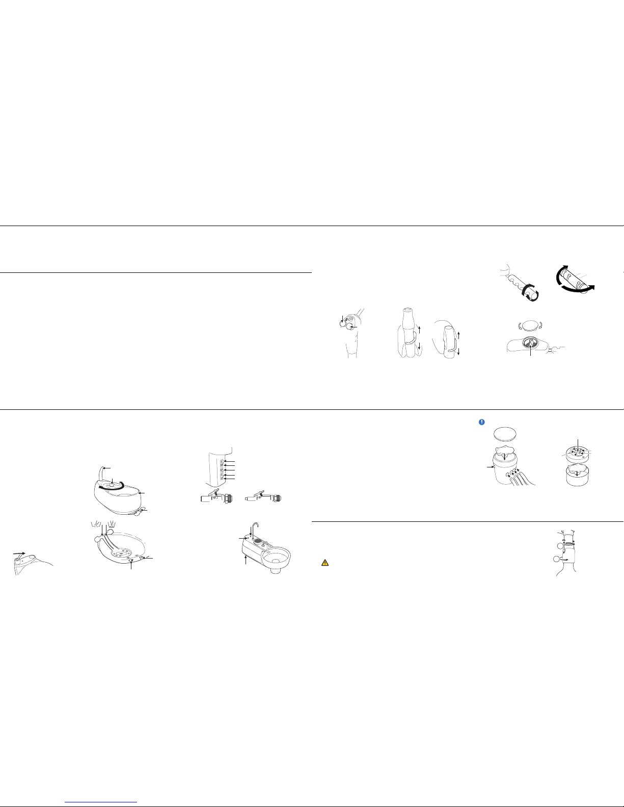
Foot control (Figure 1)
Regulates drive air and water to the active handpiece. To operate, apply pressure to the foot control for drive air.
Flip the toggle to turn the water on or o.
All controls for the Gravity Drain Cuspidor are located on the cuspidor itself.
Deluxe Cuspidor Bowl (Figure 2): Cup Fill/Bowl Rinse Controls
Figure 2 shows the actuator which is used to activate the timed cup ll and bowl rinse cycles. Rotate to desired position. Press symbol to activate.
Bowl Rinse Spout
Rotate the bowl rinse spout to desired position for bowl rinsing. Figure 2 shows the cycle time adjustment for the cup ll/bowl rinse. Turn
clockwise to increase, counter-clockwise to decrease the cycle time.
Basic Cuspidor Bowl (Figure 3): Bowl Rinse Cycle
Allows for adjusting the length of time that water will ow into the bowl. Turn the knob clockwise to increase the time, counter-clockwise to
decrease the time.
Bowl Rinse
Activates the timed bowl rinse, which provides a stream of water for rinsing. Press the button to activate the bowl rinse.
Cup Fill
Activates the cup ller, which provides a ow of water to the cup. Press the button to activate the cup ll.
All controls for the sidebox are located on the front panel. Figure 4 shows the location and identies the function of these controls.
Quick Disconnect With Flow Control
Allows the adjustment of water through the quick disconnect. Turn t he knob counter clockwise to increase the ow, clockwise to decrease the ow.
Quick Disconnect
Connection for an additional water source.
Quick-Disconnect Bottle
is quick-disconnect bottle allows for a quick and easy way to change
water bottles. (Figure 9)
Simply push up and turn clockwise to install bottle. Turn counterclockwise to remove bottle.
WARNING: For infection control, clean strainer regularly.
Visit www.ada.org for additional information.
Figure 9. Quick-Disconnect Bottle
Water Flow Adjustment QD
Routing Valve, City/Clean Water
Water Quick Disconnect
Air Flow Adjustment QD
Air Quick Disconnect
Air QD Water QD
Bowl Rinse Cycle
Adjustment
Cup Fill Cycle Adjustment
Bowl
Rinse
Cup
Fill
Cup Fill Spout
Bowl Rinse Spout
Bowl Assembly
Cup Fill/Bowl
Rinse Actuator
Figure 2. Deluxe Cuspidor Controls
Bowl Rinse
Bowl Rinse
Cycle Adjustment
Cup Filler
Figure 3. Basic Cuspidor Controls
Figure 4: Sidebox Controls
Water
On Position
Figure 1. Foot Control
Vacuum
Syringe (Figure 5)
Press water button head to activate water, press air to activate air. Pressing
both button heads will create mist.
Saliva Ejector & Standard Vacuum Valve (Hve) (Figure 6)
Flip the lever up to turn on and reverse to turn o.
1095/Canister/Quad Holder/Durr Holder (Figure 7)
For infection control, clean strainer regularly.
Strainer
TightenLoosen
Air
Water
Pressing
Both = Mist
On
Off
On
Off
Figure 6. Saliva Ejector Valve & Standard Vacuum Valve
Figure 7. 1095 (Canister & Quad Holder)
Figure 5. Syringe
Handpiece Exhaust
Located inside every control head(Euro:Canister below) is an exhaust
canister. e sole purpose for this is to trap excess oil from spraying the
inside of your control head while exhausting your handpieces. See Figure 8.
Before exhausting the handpieces, make sure that there is a 2” x 2” gauze
pad inside the canister. is is to collect and absorb the excess oil.
To prevent handpiece lubrication from contaminating the interior of the
control head, make certain the drip exhaust lines remain in the canister.
Exhaust Opening Do Not Block
Exhaust
Opening
Do Not
Block
Handpiece Exhaust Tubings
Underneath Euro Control Head Only
Handpiece
Exhaust
Tubings
Handpiece
Exhaust
Tubings
Cover
Gauze
Note: Forest Recommends Changing the Gauze Biweekly
Gauze
2 of 4
3 of 4
Figure 8. Exhaust Canister
Durr Holder - International Only
Note: Forest recommends changing the gauze biweekly.
 Loading...