


USER GUIDE

THANK YOU FOR CHOOSING THE GCQUAD
We listened to what you wanted - and created the most
accurate, versatile and game-enhancing ball and club
analysis solution available today.
The GCQuad is designed to deliver years of trusted,
reliable performance. From range practice to full
immersion simulation, whether for education or
entertainment, the GCQuad will truly change your game.
This user manual will help you better understand the
proper set-up, operation, and care of your GCQuad.
Please read it carefully and refer to it should an issue arise
during use. If you need more assistance, please contact
our customer service team for prompt, personal attention.
WELCOME TO THE REVOLUTION

INCLUDED
WITH YOUR
GCQUAD
PERFORMANCE
PACKAGE
GCQuad
Quadrascopic System
Power Adapter/Cable
Input 100-240VAC/50-60 Hz
Output 15VDC/2.4 Amps
GCQuad
Lithium Battery
Club Marker
Dispenser
Reflective
Alignment Stick
USB Type-C
Cable
TABLE OF
CONTENTS
FEATURE OVERVIEW
GETTING STARTED
SYSTEM OPTIONS
BALL PLACEMENT & HITTING
APPLYING CLUB MARKER
TARGET ALIGNMENT
CONNECTING THE DEVICEe
BATTERY CARE
STORAGE & MAINTENANCE
SAFETY
01
05
07
15
17
25
27
28
31
32

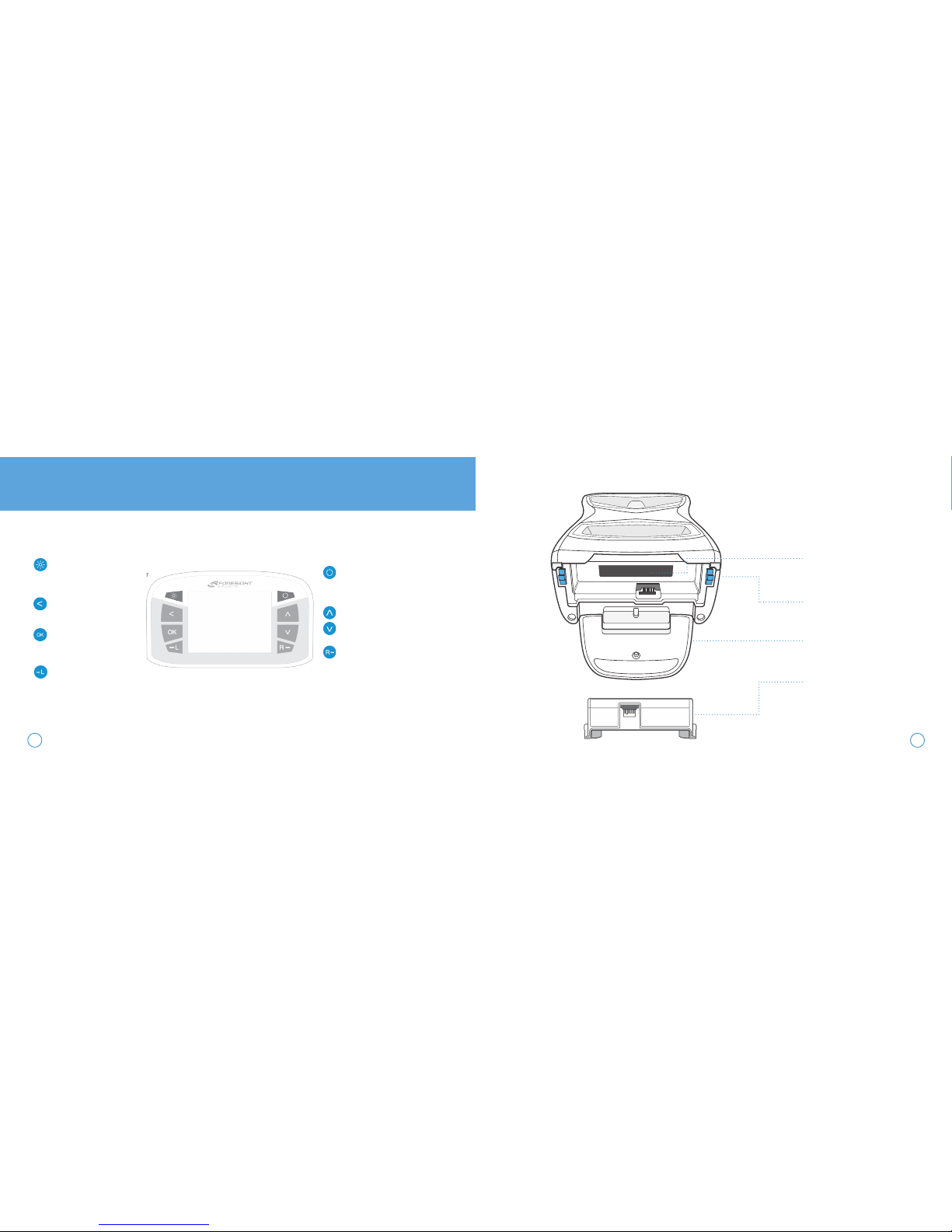
FEATURE
OVERVIEW
FRONT
1
2
POWER BUTTON
Turns device on/off
LCD DISPLAY
Displays ball placement graphic,
ball and club data, and system
options menu
Displays ball
4 TRACKING CAMERAS
High speed cameras used for ball
placement and tracking
urns device on/off
BACK
CARRYING HANDLE
POWER LED INDICATOR
Indicates whether the GCQuad is
receiving power through the power
adapter
POWER PORT
Connector for the power adapter
(included) to recharge the battery
or to operate on external power
USB TYPE-C PORT
Connector for USB Type-C cable
(included) to connect to external
PC (optional)
ETHERNET PORT
Connector for Ethernet cable (not
included) to connect to network or
external PC (optional)
#00000
LCD DISPLAY
DISPLAY BACKLIGHT
Illuminates the display for better
viewing in low light situations
BACK KEY
Return to previous screen
OK KEY
Used to access Main Menu
and select system options
LEFT HANDED TRACKING
Switches GCQuad to left handed
tracking mode, indicated by the
blinking LED
POWER BUTTON
Turns device on/off
CURSOR KEYS
Used to toggle between ball/club
data and navigate system options
RIGHT HANDED TRACKING
Switches GCQuad to right handed
tracking mode, indicated by the
blinking LED
SERIAL NUMBER LABEL
Indicates product serial number
and MAC address
BATTERY RELEASE LEVERS
Used to release removable
battery from the GCQuad
Displays ball
KICKSTAND
Deployed to provide stability on
uneven surfaces
BATTERY
Removable lithium-ion power
pack
3
4
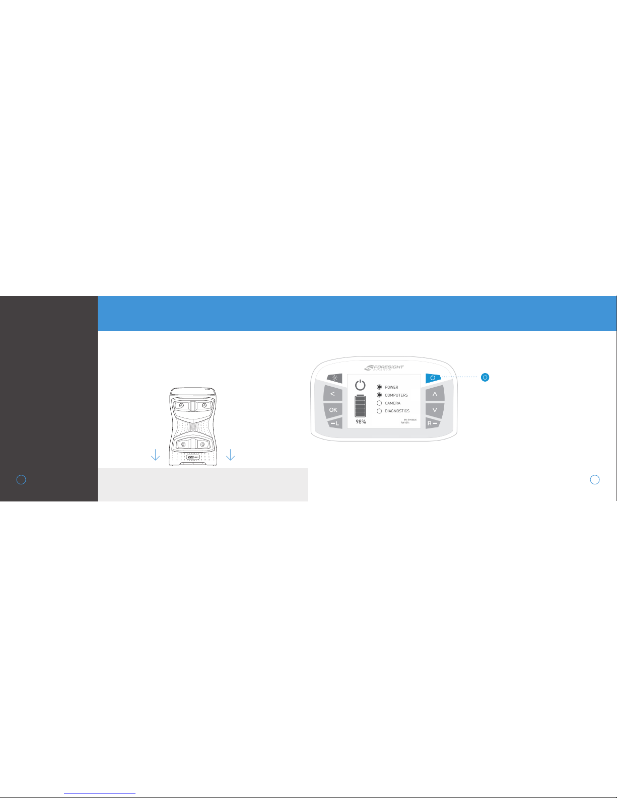
To properly use the GCQuad, place the device upright on a level
surface approximately 22” away from the hitting area. If a hitting
mat is used, make sure the device is raised to the same level as
the hitting surface. For extra stability on uneven surfaces, the
kickstand can be deployed at the bottom of the unit.
LEVEL HITTING SURFACE
To power on the GCQuad, press and release
the power button. The device will display a
start-up screen showing battery life, serial
number, and firmware version. This will take
approximately 30 seconds. The LED indicator will blink green once the GCQuad is ready
for tracking.
To power off the GCQuad, press and release
the power button again. The device will
initiate its shutdown sequence and the LCD
screen and LED indicator will turn off.
GETTING
STARTED
5
SETUP
POWER ON/OFF
POWER BUTTON
↓
↓
6
1.0.0

The GCQuad Menu Options screen is accessible by selecting
the OK key. The Main Menu consists of 5 options: Club Tracking,
Target Alignment, Settings, Diagnostics, and About. Use the arrow keys to select an option and the OK key to enter a screen.
To return to the Main Menu from inside an options screen, or to
exit the Main Menu, press the back key.
NAVIGATING THE MENU OPTIONS SCREEN
SYSTEM
OPTIONS
7

CLUB TRACKING OFF
When club tracking is turned off,
the GCQuad will track only the
golf ball. In this mode, the device
will have an LED indicator color of
blue and a larger hitting zone.
When club tracking is turned on,
the GCQuad will track both the
golf ball and golf club (with the
club markers applied). In this
mode, the device will have an
LED indicator color of green and
a smaller hitting zone. The device
will always be started with club
tracking set to ON.
CLUB TRACKING ON
10
HITTING AREA
(ball+club)
HITTING AREA
(ball only)
9

SETTINGS
Settings options can be navigated
via the cursor keys and changed
via the OK key. Once a setting is
changed, it will be automatically
saved once the screen is exited.
TARGET ALIGNMENT
The target alignment screen
shows the current alignment
configuration of the device. If
alignment has been adjusted via
the FSS Alignment Stick, the new
alignment angle will be shown on
screen.
To reset alignment to factory
default, press the OK key.
1211
SETTING DISPLAY OPTIONS
MPH | KMH | MPS
VELOCITY
DISTANCE
SPIN MODE
FACE ANGLE
AIR PRESSURE
YARDS | METERS
TARGET | PATH
AXIS & TOTAL | SIDE & BACK
AUTO | SEA LEVEL | 2500 FT | 5000 FT | 10000 FT

DIAGNOSTICS
There are two diagnostics
screens, which can be cycled
using the arrow keys. The first
(defualt) diagnostics screen
shows battery information,
available flash memory, and
shot/session information.
Accelerometer and barometer
sensor data is displayed on
screen 2.
The last shot taken can be
saved on either screen by
pressing the OK key 3 times.
During shot saving, the file
names will be displayed.
Shot saving can take up
to 60 seconds.
ABOUT
There are two about screens,
which can be cycled using the
arrow keys. The first (defualt)
about screen displays the
GCQuad model, serial number,
firmware build version, date of
manufacture, and hardware
version.
Patent information is displayed
on screen 2.
13 14

Switching between right and left handed
mode can be done using the right-handed
and left-handed tracking keys on the LCD
screen. The current mode can be determined
by the LED indicator.
Once a ball has been located by the camera, the
on-screen placement aid will appear and text
will indicate one of the following device statuses.
Ball
Only
Ball &
Club
LED BLINKS SLOWLY
Previous shot data shown on screen
No ball is detected by cameras.
LED BLINKS RAPIDLY
Ball out of hitting zone
The ball is not detected in the ball
find zone and must be moved inside.
Too many balls detected
More than one ball is detected in the
zone, excess balls should be removed.
LED REMAINS SOLID
Ready
The ball is inside of the hitting zone
and the device is ready for the shot.
BALL
PLACEMENT &
HITTING
15
The GCQuad on-screen placement
aid displays the golf ball position
relative to the hitting zone. The
center of the zone sits approximately 22” from the front of the
GCQuad, and the zone varies in size
de-pending on the mode. The zone
is approximately 14” x 14” with Club
Tracking enabled, and 18” x 14” with
Club Tracking disabled.
16
STATUS INDICATOR
18”
14”
14”

Clean the clubface with an
alcohol pad or water
APPLYING CLUB
MARKERS
In order to capture club data
with the GCQuad, club markers
must be applied to the clubface.
To apply markers using the
dispenser (included):
17
Turn the wheel clockwise to
dispense a club marker
DATA CAPTURED WITH 4 MARKERS
• CLUBHEAD SPEED
• SMASH FACTOR
• ATTACK ANGLE
• SWING PATH
• FACE ANGLE
• LOFT
• LIE
DATA CAPTURED WITH 1 MARKER
• CLUBHEAD SPEED
• SMASH FACTOR
• ATTACK ANGLE
• SWING PATH
Place club marker at the desired location
on the clubface, adhesive side down
(see images for correct fiducial placement)
Firmly apply pressure to the marker with your
finger and gently pull the tab away, leaving only
the marker on the clubface
1
2
3
4
18

FOUR MARKER
PLACEMENT FOR
DRIVERS
19
Count the club’s score lines to determine
the vertical center of the clubface.
Note: For clubs with an even number of score lines,
the vertical face center will be between the center
two score lines. For clubs with an odd number of
score lines, the vertical face center will be directly
on the center score line.
Carefully apply the first two markers
along the vertical center of the face near
the outer edge of the score lines,* keeping
both markers level with each other.
The center point between these two
markers will define the horizontal center
of the face.
Carefully apply the last two markers on
the toe of the club face at the top and
bottom edges of the ball strike zone.
1
2
3
VERTICAL CENTER
CLUB
SCORE
LINE
CENTER
TOE
MARKER
CENTER
HEEL
MARKER
TOP TOE
MARKER
BOTTOM
TOE
MARKER
score line
*Place marker about 1
marker width from the
edge of the score line
20

FOUR MARKER
PLACEMENT
FOR IRONS
21
From the bottom of the club, count score
lines up to find the approximate vertical
hitting center.
Carefully apply the first two markers
between the sixth and seventh score lines
at the toe and heel, keeping both
markers level with each other.
*
The center point between these two
markers will define the horizontal center
of the face.
Carefully apply the last two markers on
the toe of the club face at the top and
bottom edges of the ball strike zone.
1
2
3
CENTER
TOE
MARKER
CENTER
HEEL
MARKER
TOP TOE
MARKER
BOTTOM
TOE
MARKER
22
score line
*Place marker about 1
marker width from the
edge of the score line

SINGLE
MARKER
PLACEMENT
23
For best results, place the
marker high on the clubface
and as close to the horizontal
center as possible.
DRIVERS
FAIRWAYS &
HYBRIDS
IRONS &
PUTTERS
horizontal
center
recommended
placement
horizontal
center
recommended
placement

After a few seconds, both LED indicators
will show yellow and the unit will give an
audible tone. The new alignment angle
will be shown on the LCD screen.
Alignment can be viewed and reset at any
time from the Target Alignment menu in
System Options. To reset alignment to
factory default in this screen, press the
OK key. Alignment is always reset when the
unit is powered off.
TARGET
ALIGNMENT VIA
ALIGNMENT STICK
Target alignment can be adjusted up
to 10° on the GCQuad via the FSS
Alignment Stick. To adjust alignment,
place the FSS Alignment Stick in the
GCQuad hitting zone and align to your
target. Once aligned, step away from
the device to allow for it to calibrate.
25
26
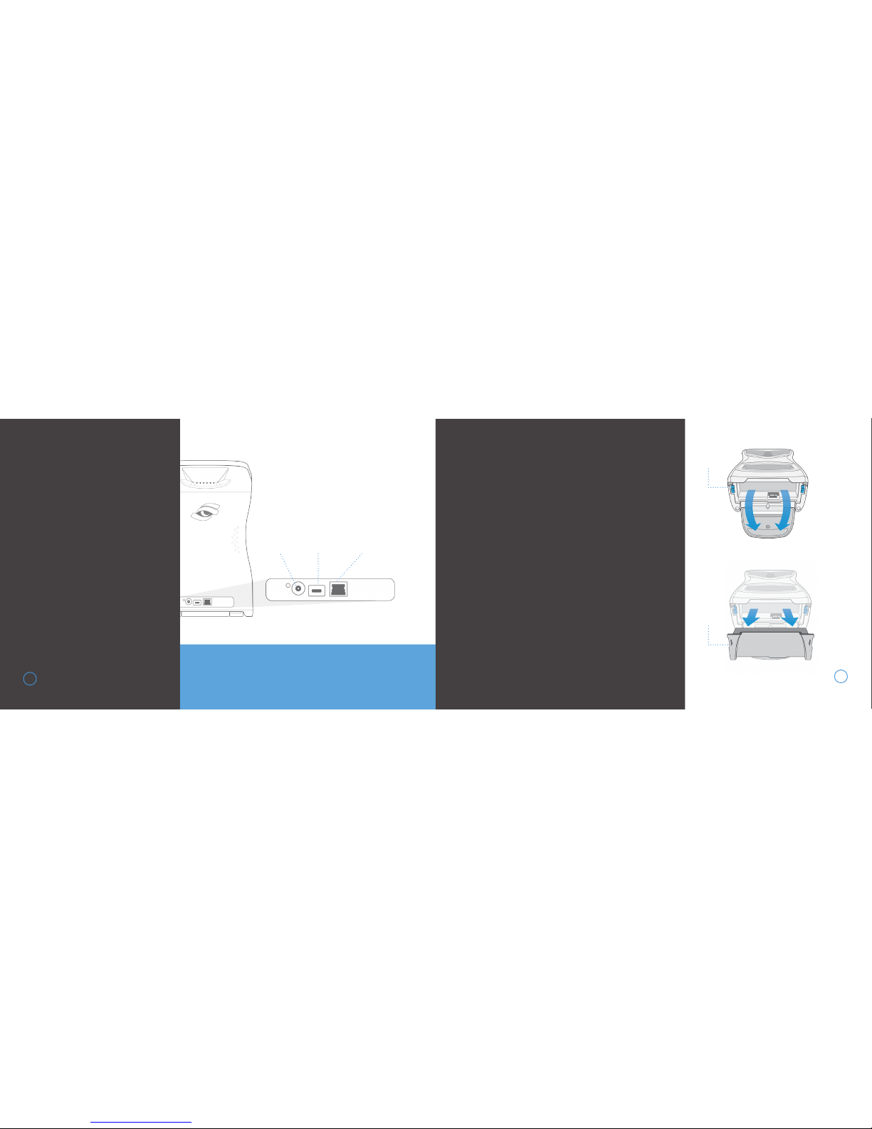
1
2
3
Turn the unit off and disconnect
from external power source
Deploy the kickstand at the bottom of the unit to expose the
battery
Firmly press on the blue battery
release levers in the direction
indicated on the battery
Once battery is released, gently
remove from the device
CONNECTING
THE DEVICE
The GCQuad can be physically
connected to other devices by
USB, Ethernet, and WiFi.
27
IMPORTANT! Do not use the USB Type-C or Power
Cables provided on ANY devices other than GCQuad.
BATTERY CARE
REMOVING THE BATTERY
4
28
POWER
USB
TYPE-C
ETHERNET
RELEASE
LEVERS
REMOVE
BATTERY

PROPER BATTERY CARE
The battery in your GCQuad has been designed to provide
safe, reliable operation. However, the life of your GCQuad
battery and its ability to hold an adequate charge is
dependent upon a regular routine of fully discharging and
recharging the battery. Without regularly performing this
discharge/recharge routine, the GCQuad battery life
expectancy can be compromised signicantly.
INSERTING A NEW
BATTERY
1 With kickstand deployed,
properly align battery as shown
2 Gently slide battery into
device
3 Once inside, firmly press on
battery to lock into place
IMPORTANT! Your GCQuad battery should be fully discharged
and recharged at least once a month. This includes batteries
in storage, as well as batteries in GCQuad devices operating on
continuous AC power.
Failure to abide by this routine may cause the battery to lose its ability
to recharge or hold an adequate charge, and will require replacement
at the customer’s expense.
30
29
DEPLOY
KICKSTAND
INSERT
BATTERY
LOCK
BATTERY
1 2 3

STORAGE AND
MAINTENANCE
Prior to storing the GCQuad, always make sure the
device is powered off and the battery is removed.
Foresight Sports strongly recommends storing the
GCQuad in a cool, dry environment in its original
foam-lined packaging or specially designed carrying
case to prevent damage.
HOW TO STORE THE GCQUAD
SAFETY
• If foreign objects or water has entered the device, disconnect the device
from external power, turn the power off, and remove the battery.
Continued use in this state can cause fire or electric shock.
• DO NOT disassemble, change, or attempt to repair the device. This
could result in electric shock and will void the manufacturer’s warranty.
• DO NOT use this device in environments where high humidity, smoke, or
dust is present.
• To avoid possible injury, DO NOT look directly into the device when it is
turned on.
• The GCQuad has been designed to withstand ball impact. However, if
the device enclosure or LCD display has been damaged due to a ball
impact or for any other reason, turn power off and discontinue use.
• Use only the power adapter that came with the device. Using any other
power adapter or charger may cause damage to the GCQuad or battery,
and may cause fire or injury.
• The GCQuad uses four digital cameras that are precisely calibrated. Do
not drop or subject the device to any impacts that may cause shock.
• After use, always store the GCQuad in a safe, dry, and dust-free
environment.
3231

© 2016-2017 Foresight Sports
Foresight Sports may have patents, patent applications, trademarks, copyrights, or
other intellectual property rights covering subject matter in this document. Except as
expressly provided in any written license agreement from Foresight Sports, the
furnishing of this document does not give you any license to these patents, trademars,
copyrights, or other intellectual property.
We’re here to help. For product related issues or
questions, please contact our customer support
team at 858.880.0179 or online at
support@foresightsports.com
QUESTIONS?

FORESIGHTSPORTS.COM
 Loading...