

Page 1
F550/F560 doc. B05
P1
doc. B05
iss V1.1
F550/F560 PICO installation manual
Description
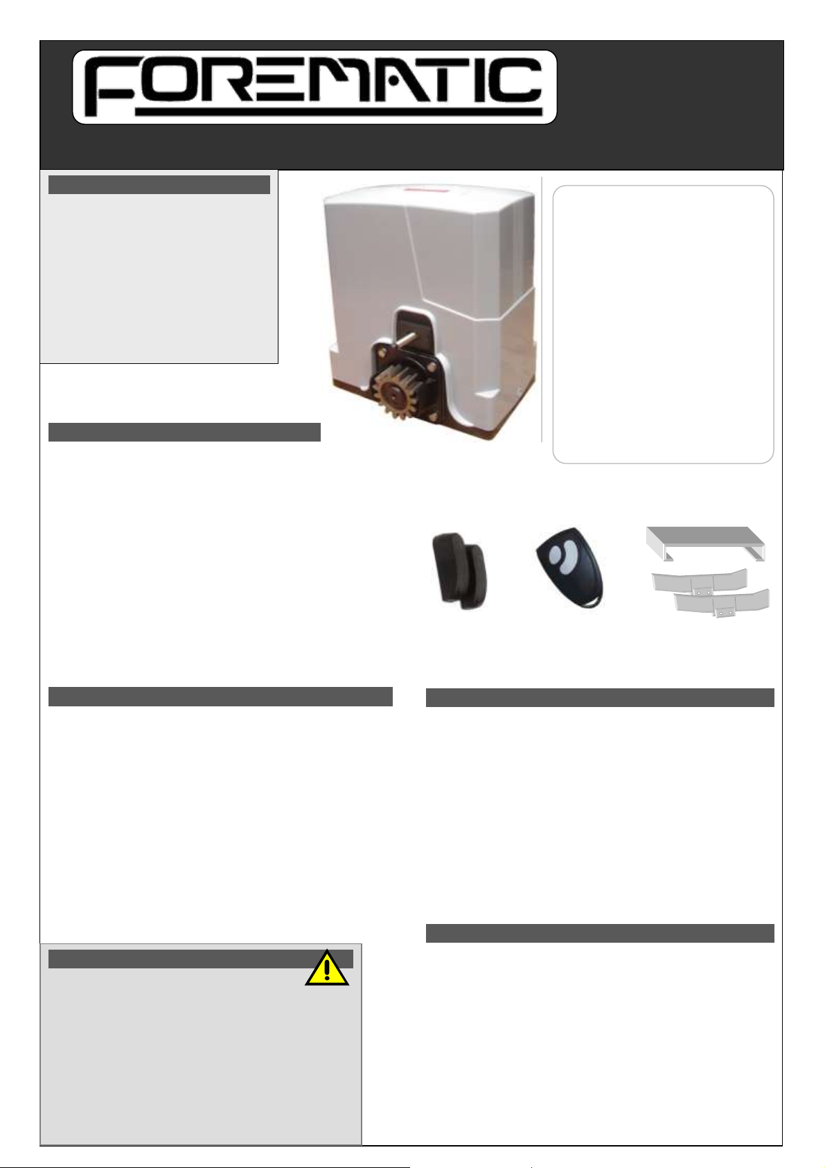
The F550 & F560 sets are based around the PICO 24Vdc sliding
gate motors. The F550 is for domestic gates. The F560 is for
light industrial gate applications such as an office development.
A toothed rack fixed to the gate engages with a pinion on the
motor. Drive is delivered through a worm drive gearbox. The gate
cannot be moved while the gearbox is engaged. A key override
disengages the motor from the drive pinion. Used in exceptional
circumstances, like power failure.
Two double button rolling code remotes are included. Buttons can
be programmed to open fully for vehicles or partial opening for
pedestrians. The 2nd button can open another gate. Up to 16
remotes can be registered. A safety photo beam is included to
detect vehicles. Further safety devices may be added.
Operation
On an input from a remote or an external control, the gate will
open fully or partially. The closed and fully open positions are
determined by limit switches acting on ‘skis’ fitted to the rack. If
the remote is activated while the gate is running, it will stop. The
next remote activation will re-start in the other direction.
For safety, the gate slows at ends of travel. If the automatic
close function is enabled, the gate will re-close after a delay.
If the photo beam is interrupted during closing, the gate stops
then re-opens. The gate will stay open while the beam is
interrupted. The motor has a stall sensor to detect physical
blocks in the gates path. If an obstacle is detected in either
direction, the gate will stop and reverse direction.
Specifications
Supply 220-240Vac 50Hz 2.5A
Pinion Mod.4 15 teeth
Speed 16mm/sec
Duty cycle 25% 20 times/hr
Gate size F550 – 600kg
F560 – 900kg
Motor power F550 – 110W
F560 – 150W
Temp O/L 120°C
Temp’ -20°C to 50°C
Protection IP44
Physical Protection
Gates must be of a robust construction to be automated without
attendance. Wheels on which the gate roll must be free running &
well maintained on clean level ground tracks. Support rollers must
be adjusted and maintained for smooth running. Gates must have
physical stops at both extremes to prevent derailment hazards.
Cables must be sufficiently protected against abrasion that could
lead to a hazard due to exposure of electrical conductors.
Electrical supplies must be protected by an earth leakage device.
There must a disconnect switch outside the gate area.
‘Automatic gate’ signs are required on both sides of the gate
warning against risk of contact injury. A pedestrian side gate is
preferred for regular pedestrian access.
User Instructions
It is the site owner or manager’s responsibility to ensure that only
trained people operate the gate, and ensure all operators are
aware of gate hazards. Operators must take responsibility for the
safety of any person within the hazard area. Never let children
play near gates in motion.
Keep the gate area clear of objects. Examine the gate for
imbalance or signs of wear. Have gate properly maintained and
repaired by qualified personnel when necessary.
Manufacturers are not responsible for injury resulting from failure
to meet the requirements in this manual. An adequate clearance
must be provided around the gate to prevent entrapment.
Photobeam
Remotes
Safety warnings
Automatic gates can be hazardous. It is the responsibility
of the home owner to be aware of the risks and provide,
adequate warning of hazards. Users should be given instruction on
the safe use of the automatic gate.
This manual is written for engineers aware of construction criteria for
automatic gates and accident prevention criteria in force in the
automation industry. Only qualified persons may do installation or
maintain work on this barrier that may change its risk assessment.
Turn off the power before working on the gate. We recommended
signage to warn users and members of the public of risk of injury to
pedestrians. Do not permit public access to the gate area. Do not use
remotes when out of sight of the gate. Do not let children or untrained
people use remotes. Do not let unsupervised children near the gate.
Description 1
User notices
Safety warnings
Warranty
Site preparation 2
Alignment
Motor & rack
Ducts & Cabling
Setup 3
Quick setup
Connections
DIP switches
Adjustment
Remotes
Wiring 4
Universal wiring
Examples
Certificate of conformity
Warranty
Page 2
F550/F560 doc. B05
P2
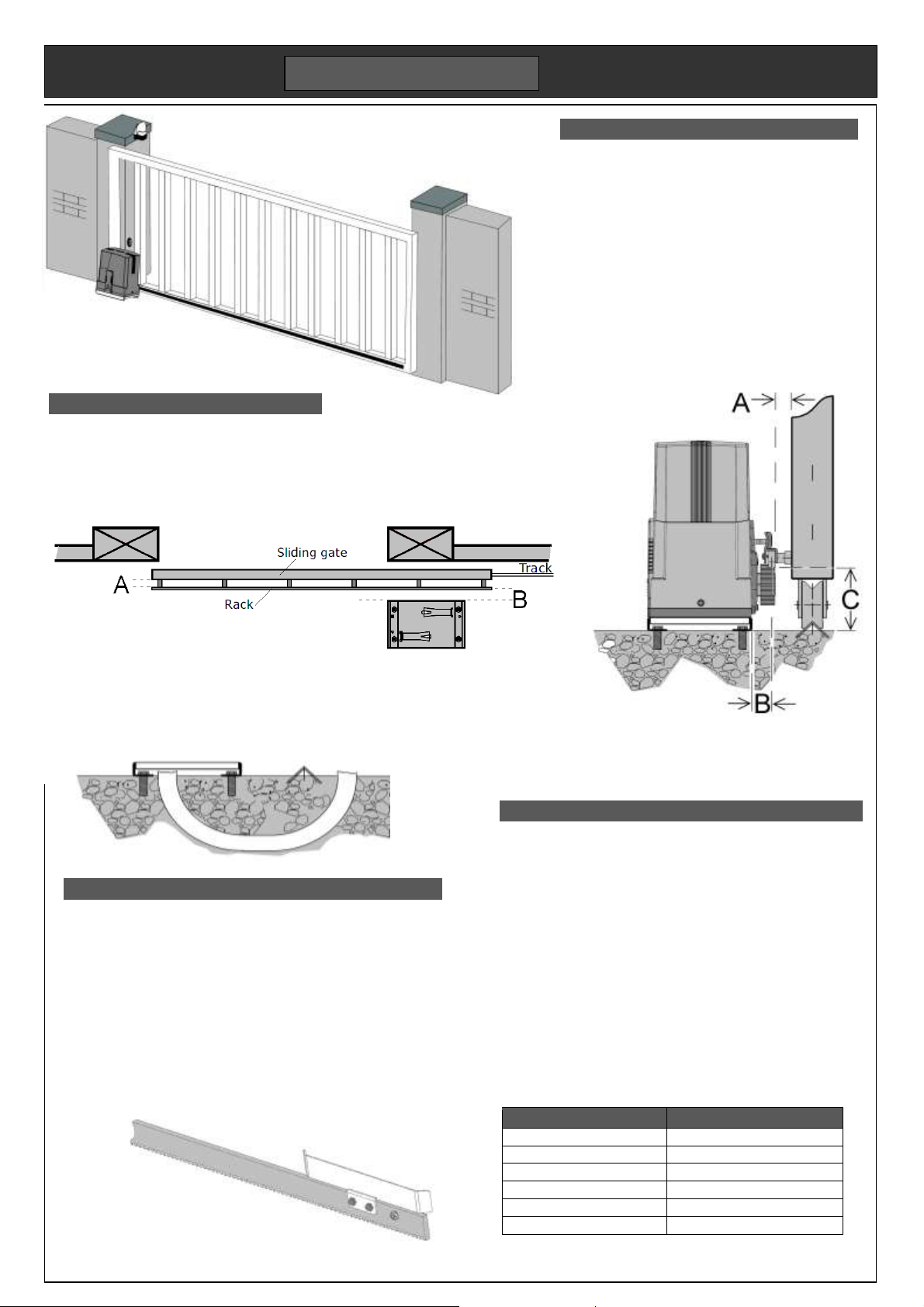
Left opening gate
Near post
Far post
Mechanical
Gates must be level and free running on a ground
track, or on cantilever gate bearings. It is usual to
support the gate at the top with nylon rollers. Two
gates mounted on the same track may slide from
each side of an opening to meet in the centre.
The motor’s steel base plate is set in concrete at
the same time as the gate track. Their relative
height will depend on the size of the gate wheel
used, typically 80 – 100mm diameter.
The motor can be packed higher to meet the rack
if required. The toothed rack normally has slotted
mounting holes to allow accurate adjustment.
Mounting the motor and rack
Slotted holes in the motor base allow some adjustment. Mount
the motor square to the gate with the rack central to the pinion.
The toothed rack is best fitted using the motor pinion to set the
height. Make the fixing near the motor, then slide the gate along
to set next fixing height. Allow a 2mm gap between rack and
pinion to reduce drag and wear. This can be done by packing
the motor up by 2mm, then remove the packing later.
Skis are brackets bolted to the toothed rack to strike the motor
limit switches. Slide the gate to the open position. Set the ski so
that it bends the spring. Repeat for the closed position. Final
adjustment can be made when motor is running.
Alignment dimensions .
A Allow 25mm from the face of the gate to the back of the toothed rack.
B Allow 30mm from the centre the toothed rack to the edge of the base plate.
C Allow a min 92mm from underside of the base plate to bottom of toothed rack.
For wheels bigger than 100mm diameter, it may be necessary to cast the base plate into
a raised concrete plinth. If not, the base plate can be bolted to a ground level concrete
pad incorporating the ground track. We recommend fixing studding with resin because
the motor’s high shear force and vibration is inclined to loosen expansion bolts. Always
use washers and self locking nuts.
Ducts & Cabling
When casting the foundations, be sure to provide one or more
cable ducts to the underside of the motor base. It will not be
possible to run cables above the gate’s ground track. While
installing the ground track, it is useful to run another duct or
direct burial cable under the track to the opposite gate post.
Align the ducts with the fifth hole in the base plate. Cables
will be required for mains supply, photo beams and any
access control devices, for example an intercom. The motor
has two cable glands in the base for the cables.
At minimum, you will need a low voltage cable to each gate
post, and a mains supply to the motor base. The cable type
will depend on the duct standard. An eight core outdoor
grade alarm cable is adequate. More than one device at the
same location can be run from one cable using the universal
wiring scheme.
Device
Rating
Photo-beam on near post
1 core + Gnd
Photo-beam on far post
3 core + Gnd
Mains supply
2 core + Earth, typ. 1.5mm²
24V lamp output
2 core, typ. 0.5mm²
230Vac lamp
2 core + Earth, typ. 0.75mm²
Intercom
4 core + Gnd
Skis fixing viewed from the motor side
SITE PREPARATION
Right opening
Page 3
F550/F560 doc. B05
P3
FZ500
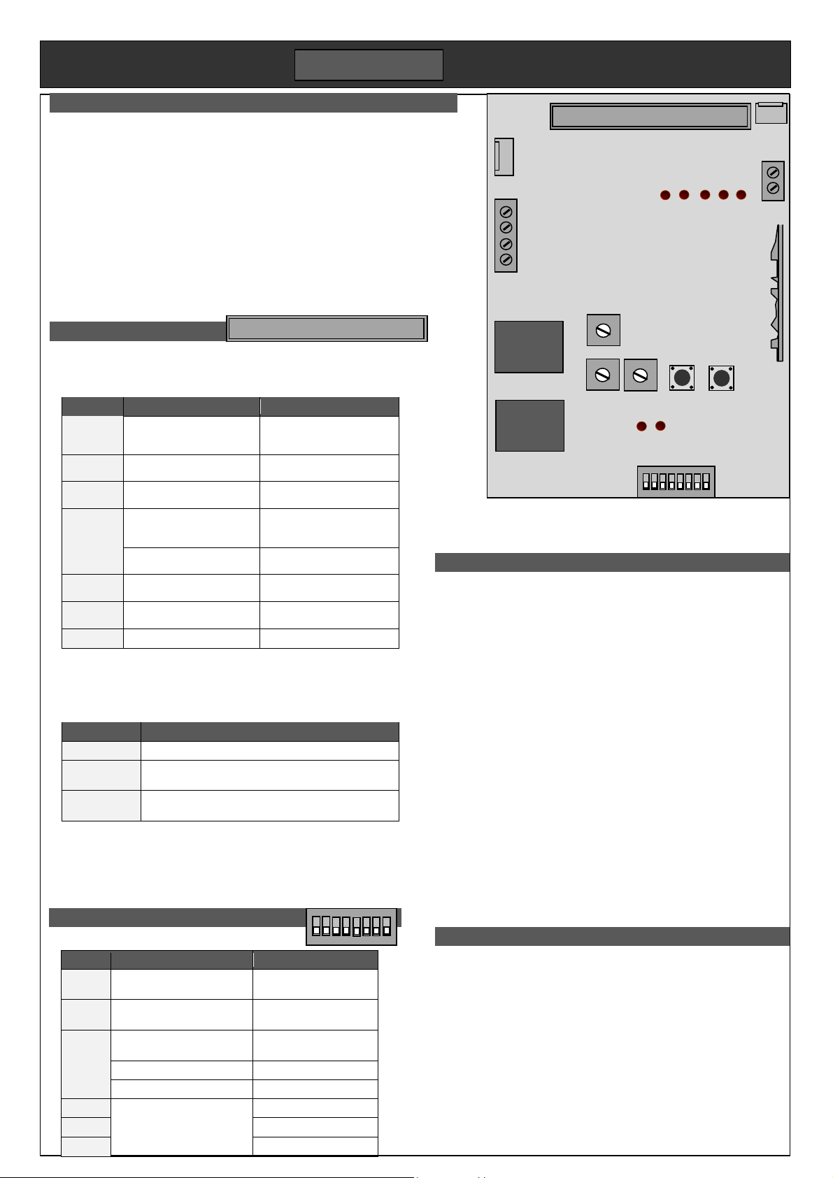
4. Adjustments
Adjustments set the safe running of the gate. Follow the order
below. On completion additional controls and safety devices can
be wired in without the need to re-adjust.
DIP switches. Typical setting; DIP1,2,3 on, DIP4 off. Refer to
diagrams on previous page for DIP5. Pause times add
together. (eg DIP6&7 ON gives 50secs).
____________________________________
RV. Speed setting. It determines kinetic energy of the gate which
affects mid travel safety. Set heavy gates to run slower.
____________________________________
LV. Sets the speed in slow down zone. Set to close the gate
firmly against the post within force test limits.
____________________________________
Force. Regulates the maximum force applied by the motor before
obstacle detection kicks in. Set it high enough to move the
gate reliably, but not much more. The finer it is set, the more
sensitive to reversal.
____________________________________
Limit learning. Reset the skis after setting speed and force then re-
run the limit learning. Hold down ST button for 5 secs until
DL5 lights then let go. Press ST again. Gate opens and stops
at the limit. Run a cycle.
5. Remotes
Each remote button must be programmed individually. Buttons can
be set for full opening (stops at limit switch), or pedestrian opening
stops after 1.5m. To enable partial opening set DIP1 off, DIP2 on.
Up to 16 remotes can be programmed in. A programmed button
when pressed, will light DL6 brightly. An un-programmed button
flashes DL6 briefly, but shows the remote is functioning.
Full opening. Press CODE button for 2secs until DL6 lights. Press
the new remote button twice. DL6 switches off
Pedestrian opening. Set DIP1 off and DIP2 on. Press CODE for
2secs until DL6 lit. Press CODE again. DL6 flashes. Press
remote’s pedestrian button twice. DL6 switches off.
1. Quick setup
Motor must be engaged with the rack and skis set for short travel.
1. Connect Mains supply to L & N terminals on power board.
2. Connect together terminals IR, Stop & Gnd.
3. Set all DIP switches down. Set LV, RV, Force anti-clockwise
4. Hold down ST button for 5 secs until DL5 lights. Let go.
5. Press ST once. Gate opens and stops at left limit.
The gate will now open and close on the remote control. A test setup can be
done on the bench for familiarity. Limits will need to be reset.
2. Connections
Control connections are made at
the top of the PCB on an 11 way plug-in screw terminal connector.
Terminal
Function
Description
Stop
Stops in either direction. On
reconnection, pauses then
re-closes.
N/C contact, returns to Gnd
terminal.
Door
Control button input
N/O button input, return to
Gnd terminal
Sync
2 motor synchronising
Connect Sync and Gnd
terminals of two motors
Lamp
24V flashing lamp or
sounder output
Switches at 2Hz while the
motor runs. Return to +24V
terminal.
24V
Accessory supply
Constant DC supply. Up to
32Vdc
IR
Safety input re-opens while
closing. Also for hold open
N/C contact, returns to Gnd
terminal.
IR 24V
Photo beam power saving
supply.
24Vdc supply on when the
gate is in moving or open.
Gnd
Ground
Common to all I/O
The power board is on top of the transformer. Connect an RCD
protected mains supply run in external grade cable. Refer to example
wiring page for more information.
Terminal
Description
220V
Mains supply. Fused with T2.5A on the board
AC lamp
(type FA40)
The lamp output ON while the motor is in
motion. Use a mains rated cable. Optional.
Batt
Backup batteries fitted below the transformer.
Optional. Use 1mm² wire.
Stop Gnd
Gnd
Door
SW2
SW1
Sync
Gnd
IR
IR 24v
Lamp
+24v
o o o o o o o o o o o
SETUP
3. DIP switches
OFF (down)
ON (up)
DIP1
Buttons - one enabled
Both remote buttons
enabled to open
DIP2
Pedestrian - disabled
Pedestrian opening
enabled by remote
DIP3
Soft stop disabled
Enables the end of
travel slow down
DIP4
Limits – (N/O for Pico)
N/C (for other motors)
DIP5
Right to open
Left to open
DIP6
Pause time
(all off disables auto-close)
+ 10secs
DIP7
+ 20secs
DIP8
+ 40secs
ON
Remotes
Pedestrian
Soft stop
Limits
Direction
10 sec
20 sec
40 sec
ANT
LED3 LED4 LED5 LED6 LED7
Motor DC
DL6 DL5
RV
FORCE LV Code ST
ON
Radio receiver 2 3
4
Stop Gnd
Gnd
Door
SW2
SW1
Sync
Gnd
IR
IR 24
Lamp
24V
o o o o o o o o o o o
Page 4
F550/F560 doc. B05
P4
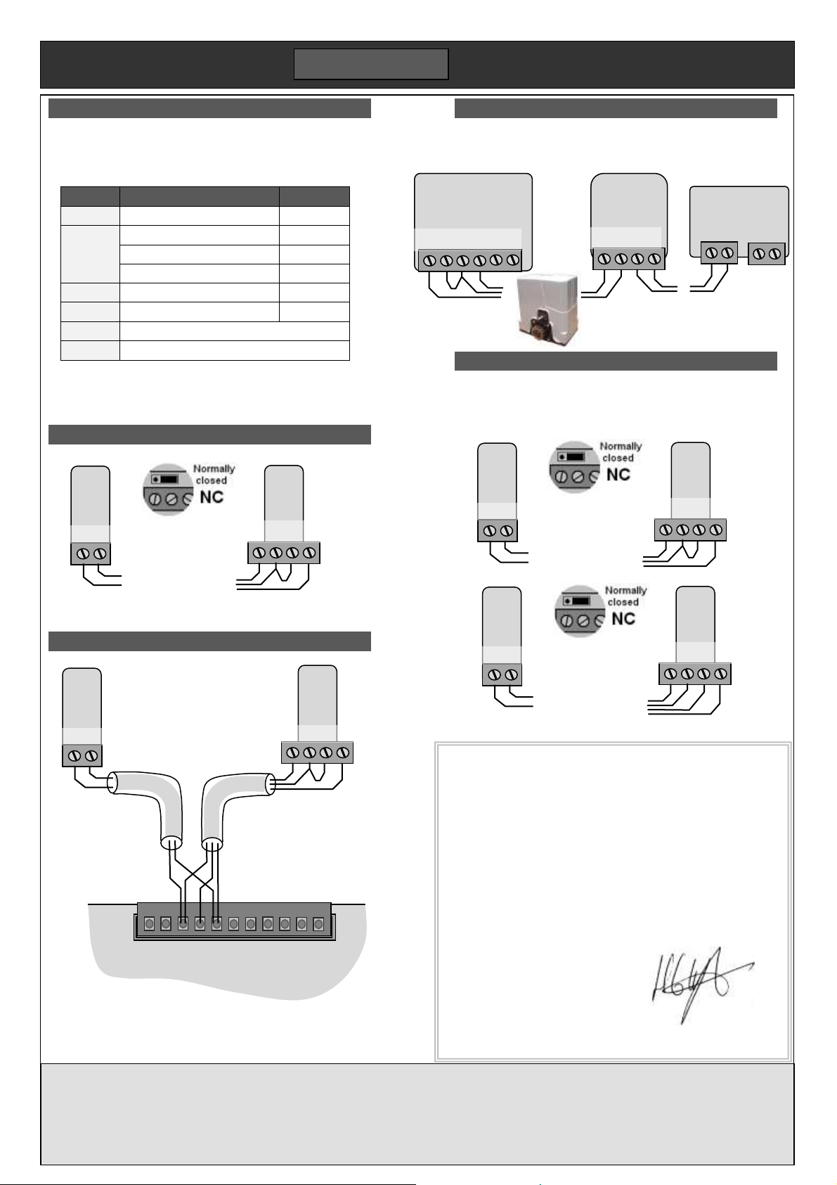
Universal wiring scheme
Following a standard wiring scheme simplifies wiring while
allowing additions in the future. For PICO we recommend an
8 core alarm cable with the following allocation.
Core
Function
Terminal
Red
Accessory supply
24V
Black
Supply & input common
Gnd
Yellow
Safety input 1
IR
Orange
Safety input 2
STOP
White
Switched accessory supply
IR24
Green
Open button
DOOR
Blue
Audio2 or pedestrian input or safety link
Brown
Audio1 or lock or DC lamp
Run a cable to each location, or from one device to the next
in a chain. Connect to the device according to the table
below. The PICO also has the benefit of wireless devices.
FA31 Photo-beam (single set)
Make sure the link on the FA31 Rx is set to NC as shown.
PICO set wiring
Minimum wiring requires only
the FA31 photo-beam below.
Run an 8 core cable to each
side. For clarity, only the cores
used have been shown.
To left post To right post
Further devices can be
added to either cable.
E.g. vehicle sensor, exit
button, intercom, keypad.
WIRING
FA31
Tx
Black White
FA31
Rx
Yellow Black White
R200 Intercom
This 2 wire intercom follows the universal wiring scheme.
Wire the power supply to the house phone (P+ & P-).
FA31 Photo-beam (double set)
The wiring is different for two photo-beams. In this scheme
the two blue wires are joined together in the control panel.
Make sure the link on both FA31 Rx is set to NC as shown.
FA31
Tx
Black White
FA31
Rx
Yell Blu Blk White
FA31
Tx
Black White
FA31
Rx
Blue Black White
Forematic
9 Vanalloys Estate
Stoke Row
Henley RG9 5QW www.forematic.com QPB05-F550
WARRANTY
3 year return to base warranty covers defective manufacture and material. The warranty does not
cover accidental damage, misuse, or abnormal wear. Warranty is conditional on good installation,
maintenance and service recommended in this manual. Warranty is void if subject of unauthorised
modification or repair, or abnormal input voltage. This does not affect your statutory rights
C-202 panel
L+ L- Go Go D/O D/O
Brown Black Green
S-22 phone
L+ L- P+ P-
Brown Blk
N-P18 PSU
P- P+ 230Vac
Stop Gnd
Gnd
Door
SW2
SW1
Sync
Gnd
IR
IR 24
Lamp
24V
o o o o o o o o o o o
-Orange
-Black
-Green
-Black
-Yellow
-White
-Red
FA31
Tx
Gnd IR24
FA31
Rx
IR Gnd Gnd IR24
Declaration of Conformity
We hereby declare, that gate openers F-550 has been manufactured
in accordance with the following standards or normative documents
EN 60335-2-95: 2004
EN 60335-1/A13: 2008/A2: 2006
EN 62233: 2008
EN 61000-3-2: 2006, + A1: 2009 +A2: 2009
EN 61000-3-3: 2008
EN 55014-1: 2006 +A1: 2009 EN 55014-2: 1997 +A2: 2008
EN 50371: 2002
In accordance with the provisions of the following directives
98/37/EC Machinery Directive with amending directives
2006/95/EC LV Directive
2004/108/EEC EMC Directive
1999/5/EC R&TTE Directive
23.03.2011 – FOREMATIC
9 Vanalloys Estate, Stoke Row, Mr H WYNN JONES
Henley RG9 5QW, United Kingdom Director
 Loading...