

Page 1

F350/F360 doc. F05
P1
Description 2
Preparation
Contents 3
Rail assembly 3
Installation
Header bracket 5
Door bracket 6
Lifting the rail 6
Rail brackets 7
Electrical 7
Programming
Initial settings 8
Remotes 11
Commissioning
Trouble shooting 12
Accessories 13
User notices
Manual disconnect 14
Safe operation 14
Warranty 15
F350 Classic
F360 Duro
doc. F05
iss V1.1
F350 / F360 Installation manual
Specifications
Supply 180-240Vac 50Hz
Speed 110mm/sec
Duty cycle 25% 20 times/hr
Temp’ -20°C to 40°C
F350 F360
Standby power <5W <6W
Door max <8m² <11m²
Motor power 100W 150W
Force 700N 1100N
Page 2
F350/F360 doc. F05
P2
Description
The F350 and F360 garage door openers are designed for
horizontally tracked domestic garage doors. Fitting to other door
types or in public areas is at the installer’s discretion.
All openers meet European norms for safety as required by EU
law. Refer to the certificate of conformity in this manual for list of
standards in compliance.
Both models use the same gauge rail which is available in
differing lengths, number of sections, and chain or belt drive.
Openers have a 24Vdc motor. An incremental encoder monitors
door position. On commissioning the opener runs a door test to
record minimum forces required. Doors cannot be moved while
the opener is engaged. An override cord on the rail disengages
the motor. Used in exceptional circumstances, eg power failure.
Remote controls vary between models. All Foresee remotes,
wireless buttons, wireless keypads are compatible with any
Foresee control panel. The opener can be set to respond to 1 of
4 channels. A home can have 4 automated doors and/or gates.
Up to 15 remotes can be registered to an opener. A safety input
is provided for optional safety photo beams or edges.
Openers are delivered in sets;
FK351 “Classic” - 700N motor, 1 piece chain drive
FP351 “Classic” - 700N motor, 1 piece belt drive
FK352 “Classic” - 700N motor, 2 piece chain drive
FK361 “Duro” - 1100N motor, 1 piece chain drive
FP361 “Duro” - 1100N motor, 1 piece belt drive
FK362 “Duro” - 1100N motor, 2 piece chain drive
User Safety warnings
Automatic doors can be hazardous. It is the responsibility
of the home owner to be aware of the risks and provide,
adequate warning of hazards. Users should be given instruction on
the safe use of the automatic door. Do not let children or untrained
people use remotes. Do not let unsupervised children near the door.
This manual is written for engineers aware of construction criteria for
automatic doors and accident prevention criteria in force in the
automation industry. Only qualified persons may do installation work
on a door that could affect the door’s risk assessment.
Turn off the power before working on the gate. We recommended
signage to warn users and members of the public of risk of injury to
pedestrians. Do not permit public access to the door area. Do not use
remotes when out of sight of the door.
DESCRIPTION
Door condition
Automated doors must be sound, well balanced, and in good
working order. Guide rollers and tracks must be free running
and well maintained. A door should be able to be lifted with one
hand, and stay in the half way position un-supported. The door
frame and ceiling mounting points must be sound to take the
opener’s weight and horizontal forces required to pull the door.
The rail length determines the door height. Max height for a 3m
rail is 2.24m. Longer rails can be specified for up to 2.8m doors.
Openers may be used on canopy doors with a convertor arm,
but at the installers risk.
Doors without an alternative access door may need an external
emergency door release in case of power failure. Remove all
bolts from the door to prevent jamming while automated.
Page 3
F350/F360 doc. F05
P3
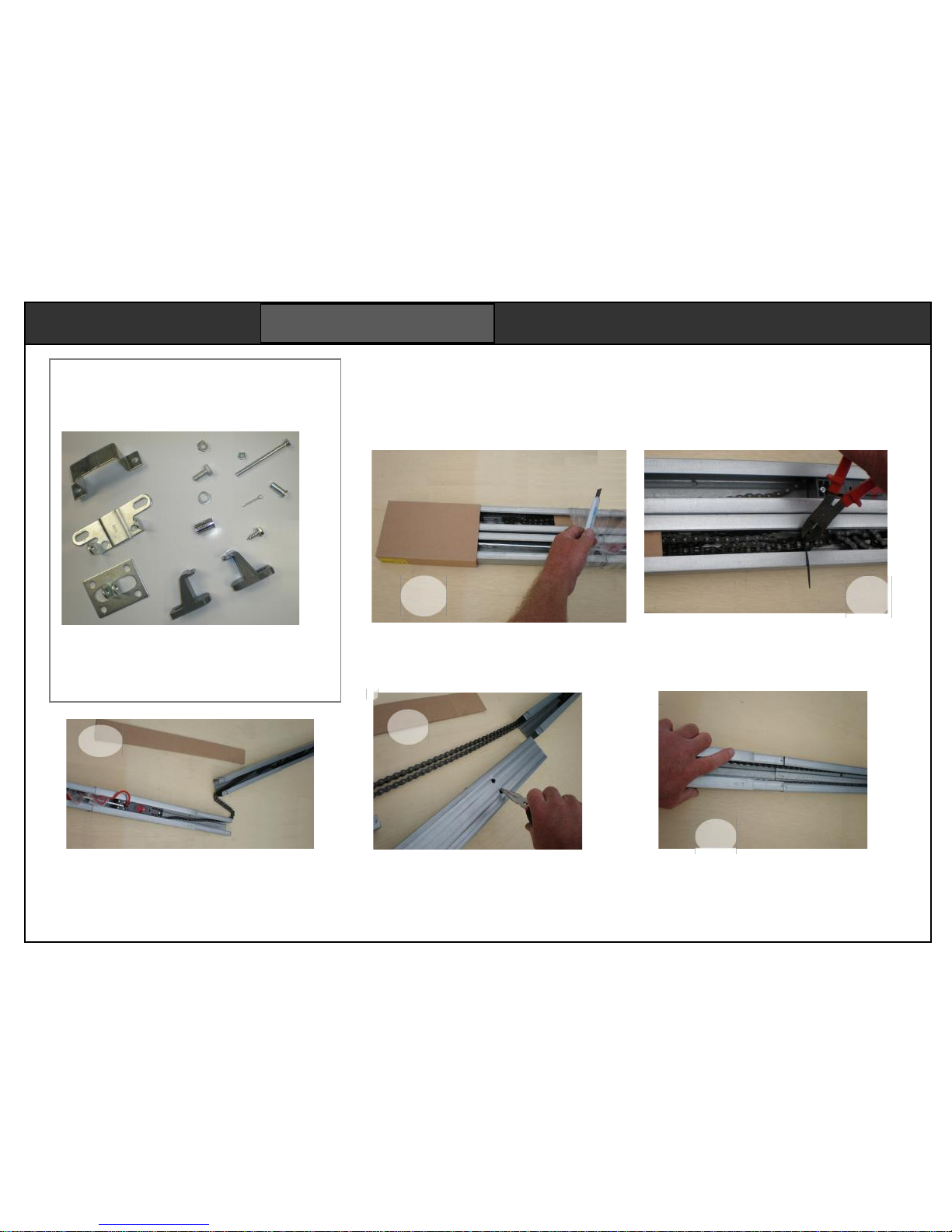
Contents
The opener carton contains a motor head,
the fixing pack above, two hangers, and a
curved arm. Remotes and accessories
depend on the set so check the carton label.
Assembling a 2 piece rail
A two piece rail pack may be ordered. to be assembled on site. Rails can be made up to
3m or 3.6m lengths. Follow the instructions below. One piece rails need no assembly.
2
Take out any cardboard packing. Snip any
packing ties that hold the chain.
Turn over the centre rail section and
turn up the four locking tabs.
Lay it down and align the rail sections
letting the chain lay flat inside the rail.
4
Slide the locking sleeves across the rail
ends. This is not easy. It best done on a
flat surface. If continues to resist, check
the ends of the rails for damage.
5
PREPARATION
Clear an area 3m long. Lay down some
cloth or carboard to keep the chain clean.
Cut off all the packaging.
1
There are two sections. The chain is
laid out through the sections. Stretch
the sections out in a line to take out
any tangles in the chain
Page 4

F350/F360 doc. F05
P4
The roof hangers may also be fitted
to the rail and motor head if you
know the roof joist positions. Apply
a finger of grease to the chain.
Turn the rail over (chain down) and fit the
rail over the motor shaft and olive. It will
need a bit of patience to align it. Fit two
saddle clamps with the four self tappers.
11
10
9
Place the motor head in its polystyrene
box for protection while assembling.
Find the olive in the accessories bag.
Fit it to the motor shaft first.
Check that the chain engages properly with
both cog wheels. The chain should be long
enough. Slacken off the spring if necessary
6
When the sections are joined together,
turn the rail over, then turn up all the
remaining locking tabs.
Be careful not to let the chain fall out
when it is upside down.
Tighten the chain checking for tension.
The chain should move sideways, but
not touch the top or bottom of the rail
7
PREPARATION
Page 5
F350/F360 doc. F05
P5
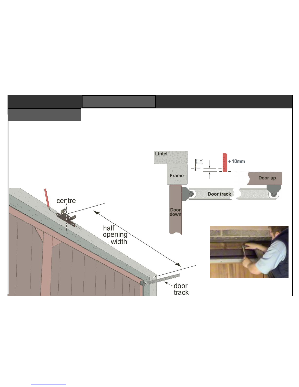
The header bracket is fixed to the door frame in the centre
of the opening. It must be set high enough for the door not
to interfere with the rail throughout the door’s travel.
Bracket height depends on the door thickness and door
roller design. Open the door to see the highest point the
door edge reaches.
Mark hole centres,
then mount the
bracket with four
suitable fixings.
The header bracket’s lower slotted mounting holes must be
at least 10mm above the highest point the door reaches.
The slotted holes can be set 200mm higher if you prefer,
but over 50mm from the ceiling.
Header bracket
INSTALLATION
Page 6
F350/F360 doc. F05
P6
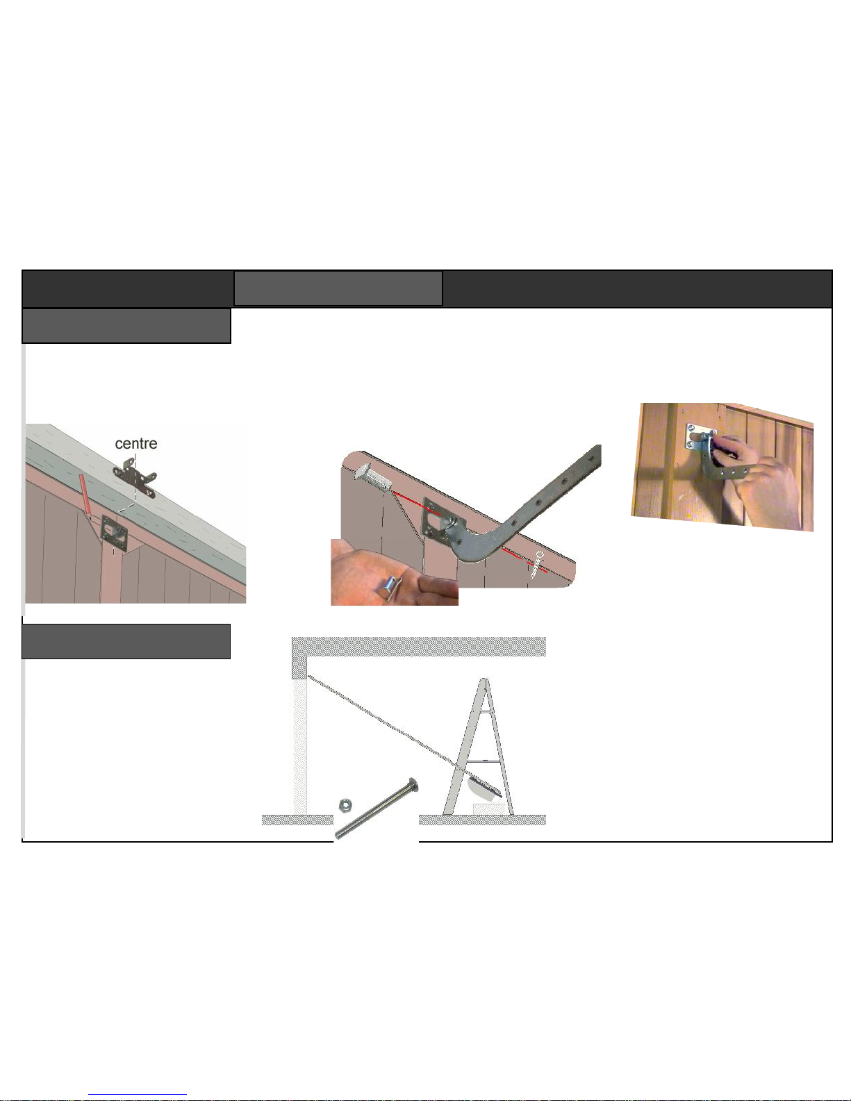
You will need a step ladder. Lean
the opener against the door frame
with the motor resting on polystyrene packaging for protection.
Fix the rail end to the header
bracket with the long bolt. Insert
the bolt thru the bracket’s square
hole first. Fix the roof hangers to
the opener head.
Lift the head onto the steps until the
rail is horizontal. Ensure the opener’s
rail is parallel with the door guides.
Run the door up & down. Check it
clears the opener. Bend the two roof
hangers ready to fix to the ceiling.
Lifting the rail
Fit the ‘J’ bar to the door
bracket with the cotter
pin. Insert the split pin.
Open one leg to secure it.
Height is not critical,
but should be within
150mm of the top of
the door.
The full force of the opener will be pulling on this
bracket. Bolting through the door is best, with the nuts
on the inside. Coach bolts have plain heads that cannot
be tampered with from outside.
Find the 8mm cotter pin, its
split pin, and the ‘J’ bar.
The door bracket fixes to the centre of the
door below the header bracket. It required
a strong fixing, so choose a structural
member of the door.
Door bracket
INSTALLATION
Page 7
F350/F360 doc. F05
P7
Run the door up and down to
make sure it clears the rail and
brackets. Then connect the ‘J’
bracket to the rail carriage.
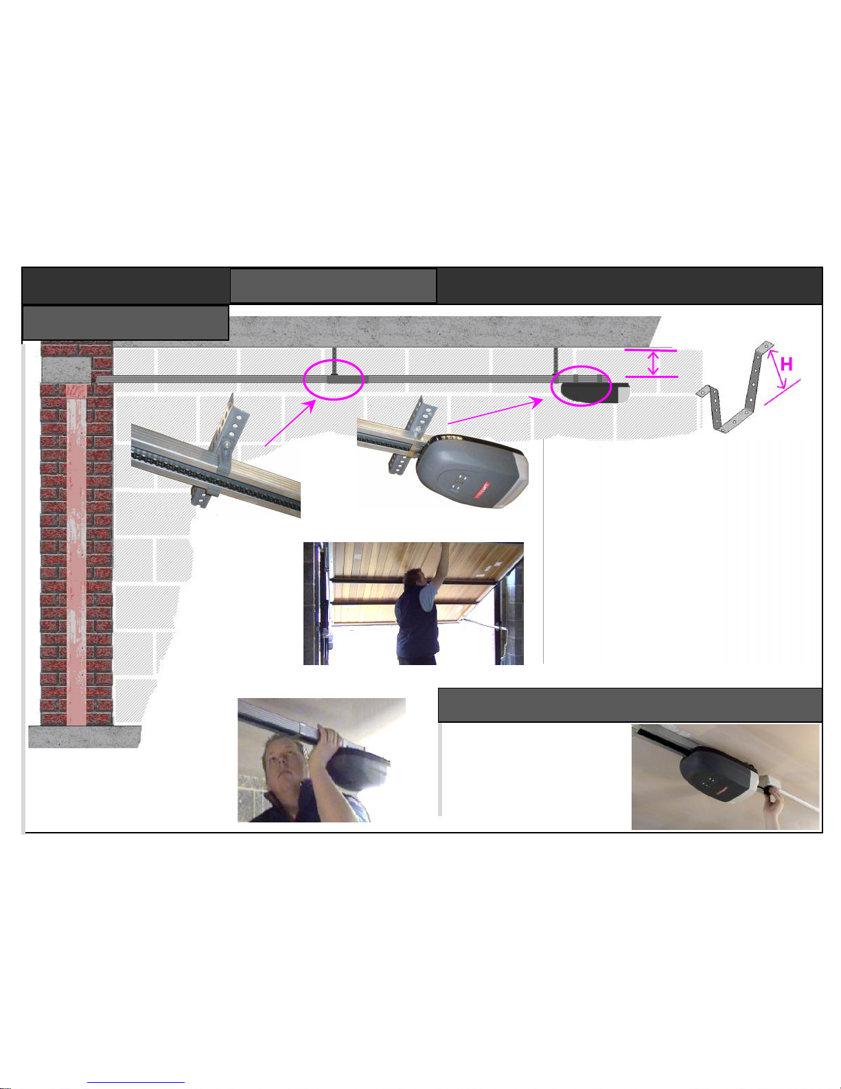
Lift the opener to the horizontal. Measure the
height H from the top of the rail to some useful
fixing points, such as a roof joist. Bend up two
‘U’ brackets from the perforated strip supplied.
Open the garage door and align the motor head
laterally. Mark the ceiling. Lower the opener,
then fix the bracket to your ceiling marks. Fix
the third saddle clamp to the rail near to the
motor head, then bolt it to the hanging ‘U’
bracket, or a piece of angle.
Fix the second ‘U’ bracket half way along the
rail. This time you must use the two plastic rail
clamps because the J bracket passes this point
Rail brackets
U bracket made from
roof hanger strip
Third saddle clamp
holding the rail near
the motor head
Check the rail is perfectly
level and secure. Brackets
may need slight bending.
The chain may scrape
inside the rail if it is not
true.
Two plastic rail
clamps holding the
rail at a mid position.
H
Electrical
The opener is pre-wired with
a UK plug. On power up, the
courtesy light will come on
and the motor will beep. The
display will then show a
circulating pattern of LEDs.
INSTALLATION
Page 8
F350/F360 doc. F05
P8
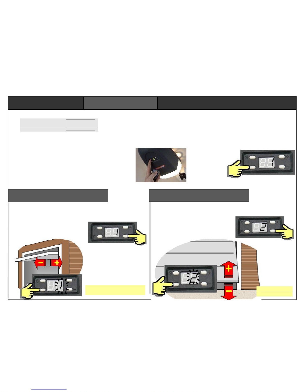
PROGRAMMING
Programmed via the 4 buttons “S”, “P”, “+”
and “-“. Key “S” stores remotes. Key “P” is an
enter button. The display shows the programme
step number. The “+” and “-“keys are used to
set the parameter. On power up the lamp comes
on, there’s a beep, then display shows a
circulating pattern.
1. Set open position
2. Set closed position
3. Force learning
4. Force setting Default = 4
5. Remote channel Default = 2
6. Alarm setting Default = OFF
7. Auto-closing Default = OFF
8. Service alarm Default = OFF
A flashing display means the parameter is waiting to be
set, or the motor is still running. Programming must be
finalised in correctly, or settings will not be saved.
Use + and – to select
step “1” then press “P”.
The “1” begins to flash.
Use + and – buttons to set
the “door open” position. The
door closes with the – button
and opens with the + button
Press “P” to save
the open setting.
Step 1 – set open position
First step sets the “door open”
position. Take care, it is the first
time a motor has lifted the door.
The open position is not critical. It
is not necessary to set the door
to the very furthest position.
Programming teaches the opener about a door.
The opener will not function until the first three
programming steps are complete. The next five
steps have default settings that are typical of
most installations. Remotes are supplied preprogrammed to the opener.
To start, press
and hold “P”
for 5 seconds.
The display
shows step 1.
Do not set the “door closed” position
too tight or the door frame will be seen
as an obstacle. Set closed point 10mm
before the door touches the frame.
You can switch between the open and
close settings but press “P” each time.
Step 2 – set close position
Use + and – to set the “door
closed” position. The door
closes with the – button and
opens with the + button
Press “P” to save
the close setting.
Use + and – to select
step “2” then press “P”.
The “2” begins to flash.
Mandatory
Page 9
F350/F360 doc. F05
P9
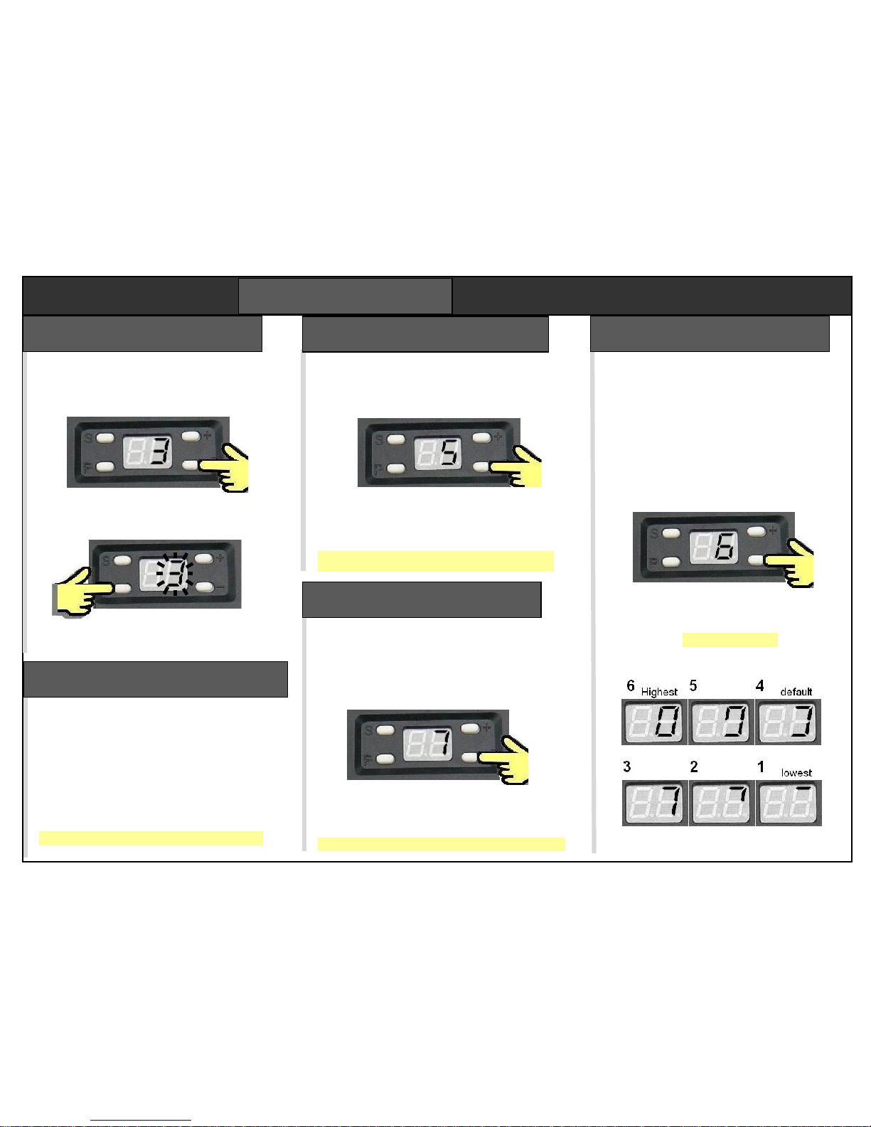
The opener runs a cycle measuring the
force required at each stage. Close the
door. Use + – keys to select step 3.
Press “P” to start the test. The 3 flashes
as the door opens. When it has stopped,
press “P” to save the force settings.
Press “P” to run a closing test. When the
door is closed fully, press “P” to save.
Step 3 – force learning
PROGRAMMING
Force setting selects the level of
additional force permitted above
minimum force learned in step 3.
There are 6 settings, displayed as
patterns on the display. Examples
are shown below. Setting 4 is the
default force, setting 6 is the
strongest force.
Use + and – keys to select step 6
then press “P” to display the force
setting character. Adjust with +
and – keys. Press “P” to save.
Step 6 – force setting
Enables a photobeam. Skip this step if
not fitted. The default setting is off.
Select step “4” then press “P”
Press “+” key to enable (beeps once),
or “-“ key to disable (beeps twice).
Press “P” to save the new setting.
Step 4 – photobeam enable
Used to test the photobeam. Skip this
step if a photobeam is not fitted. Select
step “5” then press “P”
The display shows a flashing “5” and the
door rises. Block the beam. “A” should be
displayed. If not, check wiring.
Press “P” to exit the test
Step 5 – photobeam test
This door “left open” alarm sounds after the
door is open for 10 mins. Default is off.
Select step “7” then press “P”
Press “+” key to enable (displays 1). Press
“-“ key to disable (displays 0).
Press “P” to save the new setting.
Step 7 – alarm enable
Page 10
F350/F360 doc. F05
P10
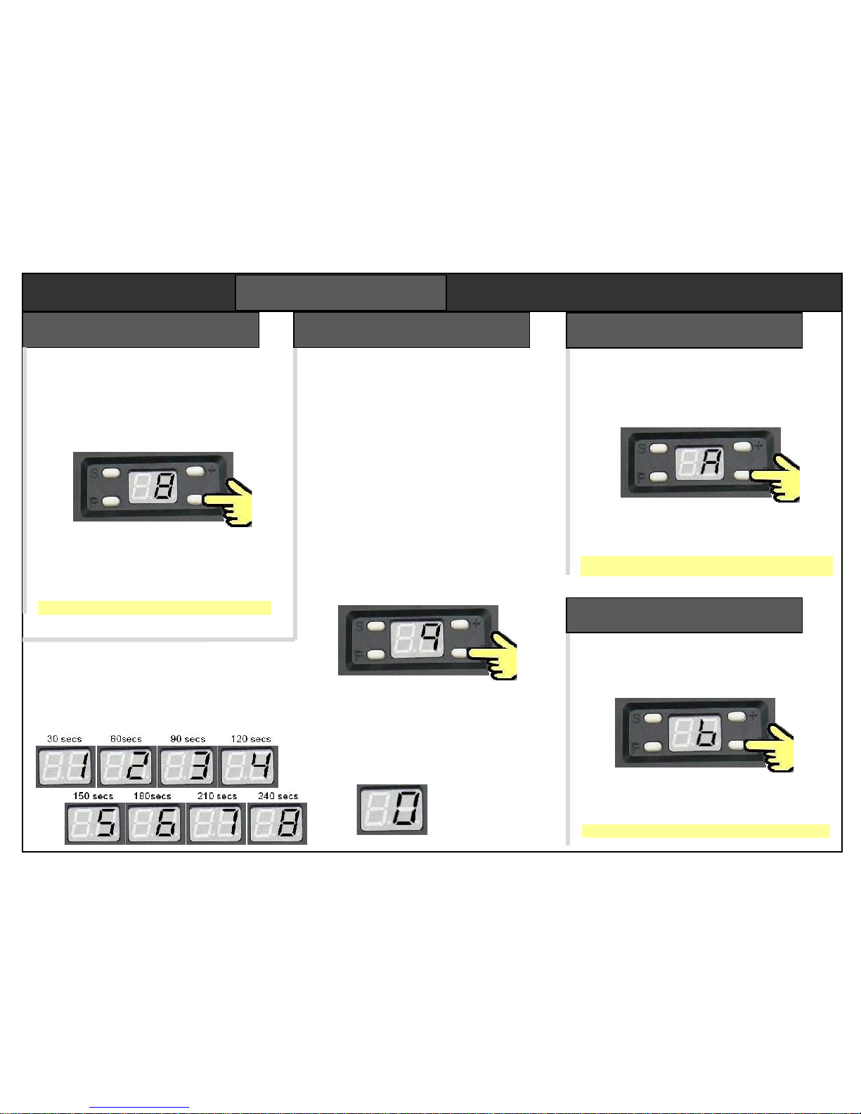
When two openers work on one remote, step
A enables both lamps can come on when
either door is opened. Default setting is off.
Select step “A” with + & – , then press “P”
The display shows a “0” for one lamp, or “1”
for both. Use the + and – buttons to select.
Press “P” to save the new setting.
Step A – lamp function
PROGRAMMING
By default the door opens on channel 2.
For double garages, it is normal to set the
second opener to channel 1. There are 4
channel options. To change channel, use
+ and – to select step “8” then press “P”
The display shows a flashing channel
number (from 1 to 4). Use the + and –
buttons to select a channel number.
Press “P” to save the new channel.
Step 8 – remote channel
Zero means the 1 for 30 secs
auto-close is off. 2 for 60 secs
3 for 90 secs
4 for 120 secs
5 for 150 secs
6 for 180 secs
7 for 210 secs
8 for 240 secs
Step 9 – auto close time
The opener can be programmed to close
after a time delay. There are nine delays
from 30 secs to 240 secs. Setting zero
disables the autoclose function.
The opener beeps and the light flashes
for 20 seconds before the door starts to
close. Opener beeps while it is closing.
When setting autoclose, you need to be
confident a car can pull in clear of the
door every time. We recommend fitting
the optional photobeam which prevents
the door closing until doorway is clear.
Select step “7” - press “P”. Displays
autoclose setting character 0 to 9.
Use + and – keys to select a delay as
required, then press “P” to save.
Sets a service alarm to sound after 2000
cycles. Reset on power down. The default
setting is off. Select step “b” then press “P”
The display shows a “0” for disabled, or “1”
for enabled. Use + and – buttons to select.
Press “P” to save the new setting.
Step B – alarm setting
Page 11
F350/F360 doc. F05
P11
For two garage doors, set left door to
channel 2, set right to channel 1.
Whichever channel is pressed, both
courtesy lights will turn on because the
remote was saved
onto both openers.
The second
button can be
used for a gate.
Four channel remotes will work 4 devices.
Each button is dedicated to a channel.
Channel setting
Programming must be finalised correctly to save
any changes you have made. Finalising can be
performed any time after completing the force
setting procedure step 3.
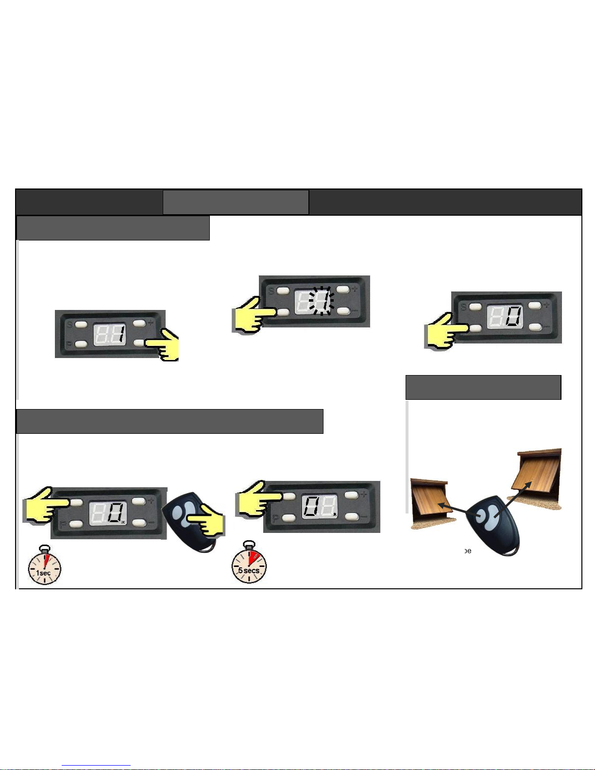
Use + key to return to step “1”.
Hold down “P” key for 5 secs,
or until display shows “0”.
Hold down “P” key for 5 secs,
or until display shows “0”.
The opener is now ready to use.
SHORTCUT
To finalise after completing step 3
(force setting) you do not need to
return to step “1”. Just hold “P”
down for 5 secs.
Step 9 – finalise programming
Remotes cannot be removed individually.
To delete one remote, the whole memory
must be cleared. Good remotes can be reentered.
Press ‘S’ for 8 secs. The 0 will
appear on the left. Holding ‘S’ for
5 secs more until the 0
disappears. The memory is clear.
Add remotes Delete remotes
Remotes supplied with openers are already
set in memory. Openers can store up to 15
remotes. To add a new remote, press “S”
for 1 sec. The point LED will light.
Press either button twice
to add. More remotes can be
added while the point is still on.
PROGRAMMING
Page 12
F350/F360 doc. F05
P12
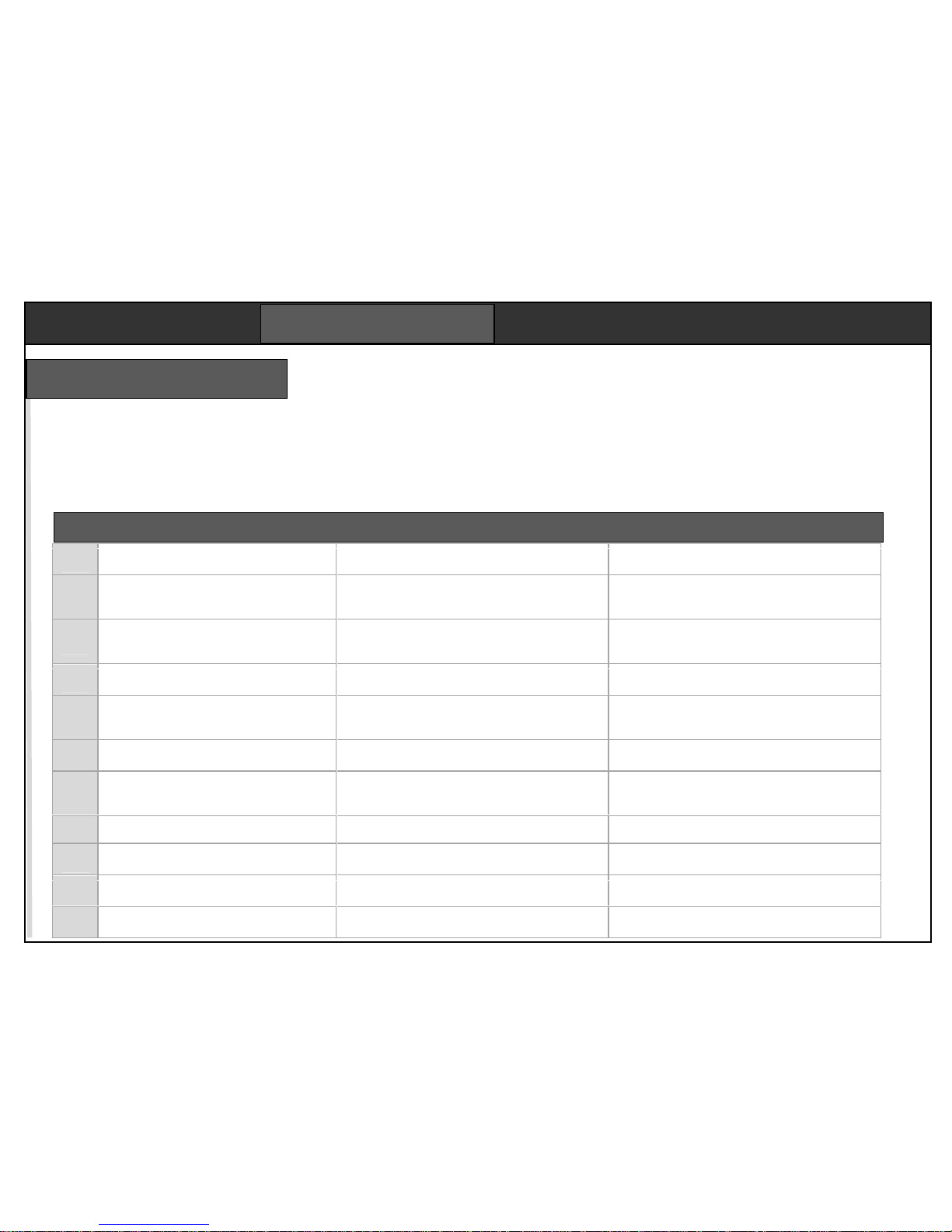
The trouble shooting table is a summary of the most common issues encountered.
Troubleshooting
DISPLAY CODES
L Limit reached (this is normal)
F force map has been exceeded
H is an encoder reading failure
A indicates the photo beam is blocked
ON POWER UP check that
The courtesy light comes on
The motor beeps once
Display shows the circular pattern
If any of these fail, check all the fuses.
FIRST CHECK
Check the power is on and the disconnect
is engaged. Try another remote. Check the
rail is correctly tensioned and that the door
is properly balanced and free running.
1
Remote will not programme in.
Is remote LED on? Is it the right remote type? Is
the memory full? Is the program light on?
The remote might be faulty. Opener problem likely.
Did you complete the “finalise programming” step?
2
Scraping noise from the rail.
Chain or belt is rubbing or jamming.
The motor can be heard straining.
Rail not flat along its length, or chain too slack. Is
the chain worn or broken? Check the chain is
wrapped around the middle of the end cog wheel.
Adjust rail centre support. Re-tension chain or belt.
Remove the motor head. Re-seat the chain on its
pulley. Check the offset ring is fitted properly.
3
Courtesy light comes on but door doesn’t
move.
If you can hear the motor running, perhaps the
release cord has been pulled. Is the chain in the
middle of the cog at the motor end.
You may be pressing the wrong button.
The disconnect is not engaged.
The chain is broken.
4
The door opens as soon as the power is
turned on.
Has the client lost a remote? Could it be under a
book or object resting on the button?
If there is a an exit button, disconnect it. Is the
FR11’s LED on all the time?
5
The door does not open after any command
Check power to opener. Door bolts not released?
Door is blocked from outside? Check the remote.
Check the supply socket with a lamp or power tool.
Clear any obstructions. Use another remote. Motor
should beep each time it gets a remote command.
6
The door almost fully closes, then
immediately opens again
Check the floor beneath the door is clear. Try
helping the door down from inside the garage.
Opener interprets the door frame as an obstacle.
Run through the close limit programming again.
7
The door gets half way down, then stops
and re-opens.
Pull the release cord. Run the door manually. Is it
well balanced? Check the door springs & cables.
Inspect the door rollers. They must not be loose.
Balance the door properly, then run through the
programming limits and force mapping. Doors will
skew if the springs are uneven or rollers are loose.
8
An ‘L’ appears on the display
This is normal. The door has reached its limit.
9
The motor runs and the chain or belt moves,
but the door doesn’t move.
Try moving the door manually. If it is jammed, then
clear the jam first. See fault reference 7.
If the door moves, the release has not re-engaged.
The door running gear may need a good servicing.
10
The door does not stop where it is set.
Check fault reference 6.
Re-do limit programming. Make sure you follow
‘finalise programming’ or settings won’t be saved.
11
Poor remote range.
Check remote batteries. Try remote. Check the
antenna cable end is not touching metal
Metal doors and foil backed plasterboard reduce
range. You may need to extend the antenna.
Symptom Points to check Remedies to try
COMMISSIONING
Page 13

F350/F360 doc. F05
P13
We recommend the wireless accessories
which require only programming
FA62 Wireless keypad
FR11 Wireless button
Openers have a 12Vdc supply suitable
to power access controls and sensor
devices of your choice.
FA30 Photobeam
FA61 Keyswitch
VY805 Wired button
Wired connections are made to screw
terminals on the main PCB. They have
been colour coded for simplicity. All 5
wires connect to one corner of the PCB.
See below for wiring.
GREEN Button input
VIOLET +5Vdc (button com)
BLUE Ground (photobeam com)
YELLOW Photobeam input
RED +12/15Vdc
Refer to the wiring notes supplied with
each accessory for more information.
Button input GREEN & VIOLET
Keypad power BLUE (-) & RED (+)
Keypad contact GREEN & VIOLET
Safety edge BLUE & YELLOW
Accessories
The FA30 optional photo beam prevents
the door closing if the beam is blocked
by a car or any other object. If an object
moves into the beam while the door is
closing, it will stop and re-open. Used
when the automatic closing is enabled.
Photo beam fitting
This device requires a four core cable to each
side of the door frame. Mount the two photo
beam elements on brackets fixed to the inside
door frame 250mm above floor level. No door
parts must cross the beam in normal travel.
Keep the cable clear of moving door gear. Any
damage will stop the door closing.
The photobeam function must now be enabled
in the programming. See step 4.
COMMISSIONING
PCB
There is a single PCB with a number of connectors
for dedicated functions. Two screw terminals in the
corner are for the accessory connections. Switch
the power off before taking the housing off.
There are two 2.5A fuses, one for the lamp, one for
the transformer. Bulb type is a 230Vac 25W E14
accessible through the white cover.
Page 14

F350/F360 doc. F05
P14
Maintenance & repair
An opener fitted and maintained to these
instructions will give long reliable service.
The door’s running gear must be kept in
good working order. We recommend the
door is operated manually at least once
per month to check for wear. Openers will
hide problems developing within the door
tracks and springs. Faults not attended to
early may develop.
Opener damage resulting from poor maintenance is not covered by the warranty.
Spares are available from your dealer. For
safety, only competent persons should be
allowed to fit spare parts.
Programming steps 1,2,3 and 6 should be
repeated if the motor or drive train parts
are replaced. All programming will need
to be repeated if the PCB is replaced.
Garage doors and openers can be dangerous. These safety
warnings are to protect users of automated doors. Cut this
label out and stick it to the door, or download a new copy.
Safe operation
Warning – AUTOMATIC DOOR
Do not let children operate or play with remotes.
Never go under the door when partially open.
Operate the door only when in eye contact.
Keep the door regularly maintained.
Make sure there are no people or objects
in the path of the moving door.
Only authorised and responsible
persons should be allowed to
use the door controls.
Manual operation
A disconnect pull cord is fitted to the rail
to allow the door to open in the unlikely
event of a power failure. Pull once, then
lift the door manually.
The door will re-engage
the drive automatically
on the next cycle.
A door mounted release
is available for releasing
the door from outside.
USER NOTICES
Declaration of Conformity
We hereby declare, that Remote Controlled Garage Door Openers
F-350M, F-350G 240V have been manufactured in accordance with
the following standards or normative documents ;
EN 60335-2-95: 2004
EN 60335-1/A13: 2008/A2: 2006
EN 62233: 2008
EN 61000-3-2: 2006, + A1: 2009 +A2: 2009
EN 61000-3-3: 2008
EN 55014-1: 2006 +A1: 2009 EN 55014-2: 1997 +A2: 2008
EN 50371: 2002
In accordance with the provisions of the following directives
98/37/EC Machinery Directive with amending directives
2006/95/EC LV Directive
2004/108/EEC EMC Directive
1999/5/EC R&TTE Directive
23.03.2011 – FOREMATIC
9 Vanalloys Estate, Stoke Row, Mr H WYNN JONES
Henley RG9 5QW, United Kingdom Director
Page 15
F350/F360 doc. F05
P15
Forematic
9 Vanalloys Estate
Stoke Row
Henley RG9 5QW www.foresee.eu.com QP-F380
Period
The purchaser is granted a warranty covering the safe and reliable function of the
Foresee Garage Door Operator (Mechanics, Motor and Motor Control Systems) for a
period of 3 years from the date of purchase. The warranty period for replacement parts
is 6 months or to the end of the current warranty period, which ever is longer.
Requirements
Warranty claims are only applicable in the country where the Operator was purchased.
The product must have been purchased through our authorised distribution channels.
The warranty only covers damage to the contract object. The fully completed warranty
card together with the receipt of purchase correspondingly dated substantiates your
right to claim under the warranty.
Performance
During the warranty period we undertake to rectify any and all defects to the Foresee
product which can be proved to be attributed to a material or manufacturing fault. We
will, at our discretion, either exchange a defective product for a fault free product,
repair it or make a refund. We do not accept costs for dismantling and installation, or
for carriage. Parts replaced under warranty are the property of the warrantor.
Warranty exceptions
The warranty does not cover damage caused through:
Wear & Tear
Improper Installation
Negligent Care and/or Maintenance
Improper Initial and/or Subsequent Use
Negligent or Wanton Destruction
External substances such as water, salt, alkaline or acid solution
Abnormal Environmental Influences
Mechanical damage through improper Transport and/or Installation
Additional Priming or other Surface Protection treatments
Repair by Non-qualified or Incompetent Persons
Using non-Foresee parts without the Approval of the Manufacturer
Removal of product Identification, or otherwise making it unidentifiable
A separate 2 Year warranty is granted on Radio Equipment, accessories and system
controls. There is no warranty on Consumables (eg fuses, batteries, bulbs)
Warranty
USER NOTICES
 Loading...