


VC204XE Dual HD+ 4 SD Signals + Audio Capture Adapter
User’s Guide
Rev 1.0
10/4/2012

Content
1 Preface .......................................................................................................................................... 1
2 Minimum Hardware Configuration .............................................................................................. 1
3 Recommended Hardware Configuration ...................................................................................... 1
4 System Requirements ................................................................................................................... 1
5 Hardware and Driver Installation ................................................................................................. 2
6 Connection of HD Input ............................................................................................................... 2
6.1 DVI-D/DVI-I Signal .............................................................................................................. 2
6.2 HDMI Signal .......................................................................................................................... 3
6.3 VGA Signal(RGB-HV) .................................................................................................... 3
6.4 YPbPr Signal .......................................................................................................................... 4
6.5 CVBS ..................................................................................................................................... 4
7 Connection of SD Input ................................................................................................................ 5
8 Connection of Audio Signal ......................................................................................................... 5
9 Video Capture Device Instruction ................................................................................................ 6
9.1 Display "Filter Properties Dialog Window" In Common Software ....................................... 6
9.2 “Device” Instruction .............................................................................................................. 7
9.3 HD Capture Device "Advanced Settings" Instruction ........................................................... 8
9.3.1 Input Signal ........................................................................................................................ 8
9.3.1.1 Input Interface .................................................................................................................... 8
9.3.1.2 Signal Status ....................................................................................................................... 9
9.3.2 Image Adjustment .............................................................................................................. 9
9.3.3 Image Output .................................................................................................................... 10
9.4 SD Capture Device” Advanced Video Settings” Instruction ............................................... 11
9.4.1 "Color Adjustment" Instruction ........................................................................................ 12
10 Video Formats Setting ................................................................................................................ 12
10.1 Display "Filter Output Pin" In Common Software .............................................................. 13
10.2 “Out Format” Instruction ..................................................................................................... 13
11 Audio Capture Device Instruction .............................................................................................. 13

11.1 Windows XP, Windows 2003 .............................................................................................. 14
11.2 Windows Vista, Windows 7, Windows 2008, Windows 2008 R2 ...................................... 15
12 Compatible Software Instruction ................................................................................................ 16

1 Preface
Thank you for purchasing VC204XE HD video capture adapter!
The VC102XE is featured with small and exquisite bulk, superior performance and
flexible characteristics. The VC204XE capture adapter can simultaneously capture two
High-Definition video signals, four Standard-Definition video signals, and two stereo
analog audio signals. The HD input can connect with HDMI, DVI, YPbPr, VGA
(RGB-HV), composite video broadcast signal (CVBS).
The user’s guide will provide with necessary instruction for proper use of VC 204XE.
2 Minimum Hardware Configuration
Intel Core Solo
1G of RAM
Available PCI-Express x4 expansion slot on motherboard
3 Recommended Hardware Configuration
Intel Core i5
2G of RAM
Available PCI-Express x4 expansion slot on motherboard
4 System Requirements
System should be one of the following systems (x 86 version or x64 version):
Microsoft Windows XP
Microsoft Windows Server 2003

Microsoft Windows Vista
Microsoft Windows Server 2008
Microsoft Windows 7
Microsoft Windows Server 2008 R2
5 Hardware and Driver Installation
Please refer to "VC204XE Installation Guide" to install the hardware and the driver.
6 Connection of HD Input
6.1 DVI-D/DVI-I Signal
Figure 1, DVI signal connection sketch map

6.2 HDMI Signal
Figure 2, HDMI signal connection sketch map
6.3 VGA Signal(RGB-HV)
Figure 3, VGA signal connection sketch map

6.4 YPbPr Signal
Figure 4, 6.4 YPbPr signal connection sketch map
6.5 CVBS
Figure 5, CVBS connection sketch map

7 Connection of SD Input
Figure 6, CVBS on connection of SD interface sketch map
8 Connection of Audio Signal
Figure 7, audio line in signal connection sketch map
Notes: The audio signal input is up to" Line in" level standard, if you need to connect
microphone , must connect microphone with microphone input of "microphone
amplifier" or "mixer" , and then "microphone amplifier" or " mixer "output is
connected to the interface.

capture card will not work. You have to return the capture card back to factory for
being repaired.
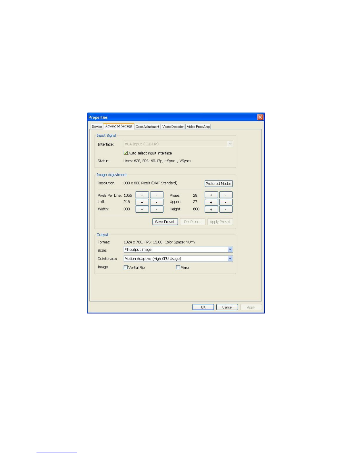
9.3 HD Capture Device "Advanced Settings" Instruction
Figure 9, "Advanced Settings " page
9.3.1 Input Signal
9.3.1.1 Input Interface
By default, select “
Auto Select Input Interface
”, supporting input interface includes:
DVI / HDMI input, VGA input, YPbPr input, CVBS input.

9.2 “Device” Instruction
Figure 8, Device Properties tab
Device Number: display serial of VC204XE, the number should be accorded with the
barcode on the card.
Version: display related version number, versions include hardware version,
firmware version, driver version, and device serial. You may request user to provide
relevant version number when you solve problems.
Firmware: if new features need to upgrade the firmware, we should first backup it
and then upgrade the firmware.
Notes: The different versions of the firmware and hardware cannot be mixed together,
or else it will get error when upgrade. Additionally, do not power outage in the
process of firmware upgrade, otherwise it will lead to upgrade firmware fail, then the
capture card will not work. You have to return the capture card back to factory for
being repaired.
9.3 HD Capture Device "Advanced Settings" Instruction
Figure 9, "Advanced Settings " page
9.3.1 Input Signal
9.3.1.1 Input Interface
By default, select “
Auto Select Input Interface
”, supporting input interface includes:
DVI / HDMI input, VGA input, YPbPr input, CVBS input.

Notes: when “
Auto Select Input Interface
” is selected, if HDMI and YPbPr input
interfaces both have signal access, then HDMI input is preferred. You must select
CVBS input manually, otherwise it will be identified with component input. Signal
must access Y interface (green RCA interface). In fact, the capture card can capture 6
SD signals coupled with other four CVBS inputs which VC204XE offers.
9.3.1.2 Signal Status
The relevant parameters of signal are shown, such as total number of rows, frame rate
(p is progressive scan, i is interlaced), mode, audio frequency.
9.3.2 Image Adjustment
By default, image is auto, but auto cannot achieve desired effect, such as black border,
unclear image, picture which needs clipping, it must be adjusted manually. After
adjustment, you can save the preset. Then you can apply preset values without
adjustment when the same signal accesses.
For example as VGA signal adjustment:
Black border adjustment: Through adjust left margin and top margin to eliminate
black border. Every time you can adjust 1 pixel.
Text definition adjustment: adjust line number of samples and sampling phase to
achieve desired definition of text.
Select correct resolution quickly: the capture card cannot identify correct resolution
with the same number of rows, such as 1024x768, 1280x768, 1360x768, 1368x768,
lines are all 768, auto may be all identified as 1024x768, then click “auto”, a list will
pop up as shown below, user can select the correct resolution.
Figure 10, auto pop-up menu

Image clipping: Through adjust image width, height, left margin and top margin to
achieve desired requirement. Increasing/reducing width of image starts from right,
increasing/reducing height of image starts from bottom.
Skills of image clipping as follows:
1. Set scale “fill output image” to confirm whether clipping adjustment is
appropriate.
2. Cut off image left: firstly increase left margin, then reduce image width.
3. Cut off image right: reduce image width.
4. Cut off image top: firstly reduce image height, and then increase top margin.
5. Cut off image bottom: reduce image height.
After image adjustment completes, click "Save Preset" to save current adjustment;
click "Del preset" to delete preset you saved; click "Apply Preset" to apply the saved
preset to current settings.
9.3.3 Image Output
Display output format of current image, set image zoom scale, deinterlace and image
flipping.
Format:
display output image size, frame rate, color format.
Scale:
provide three ways, full output image and keep aspect ratio, fill border
to black and keep aspect ratio, clip border.
Deinterlace:
vertial blend, motion adaptive. Motion adaptive is better, but it
takes up high CPU usage, also you can selcet “disabled”.
Image :
offer two ways, vertial flip and mirror.
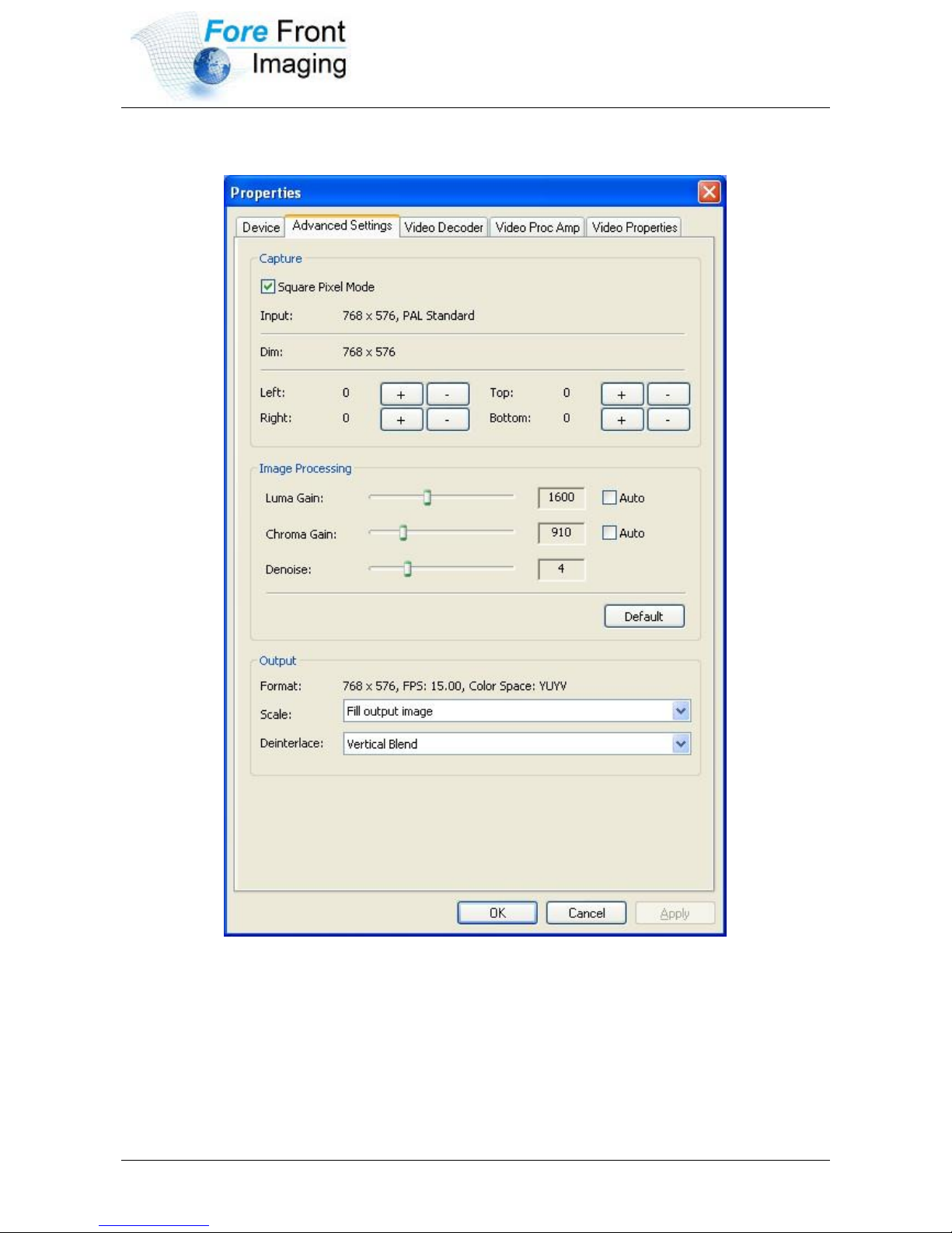
9.4 SD Capture Device” Advanced Video Settings” Instruction
Figure 11, SD Capture Device” Advanced Video Settings” page
SD capture device” Advanced Video Settings” is unified with HD capture device,
except input interface has only CVBS.
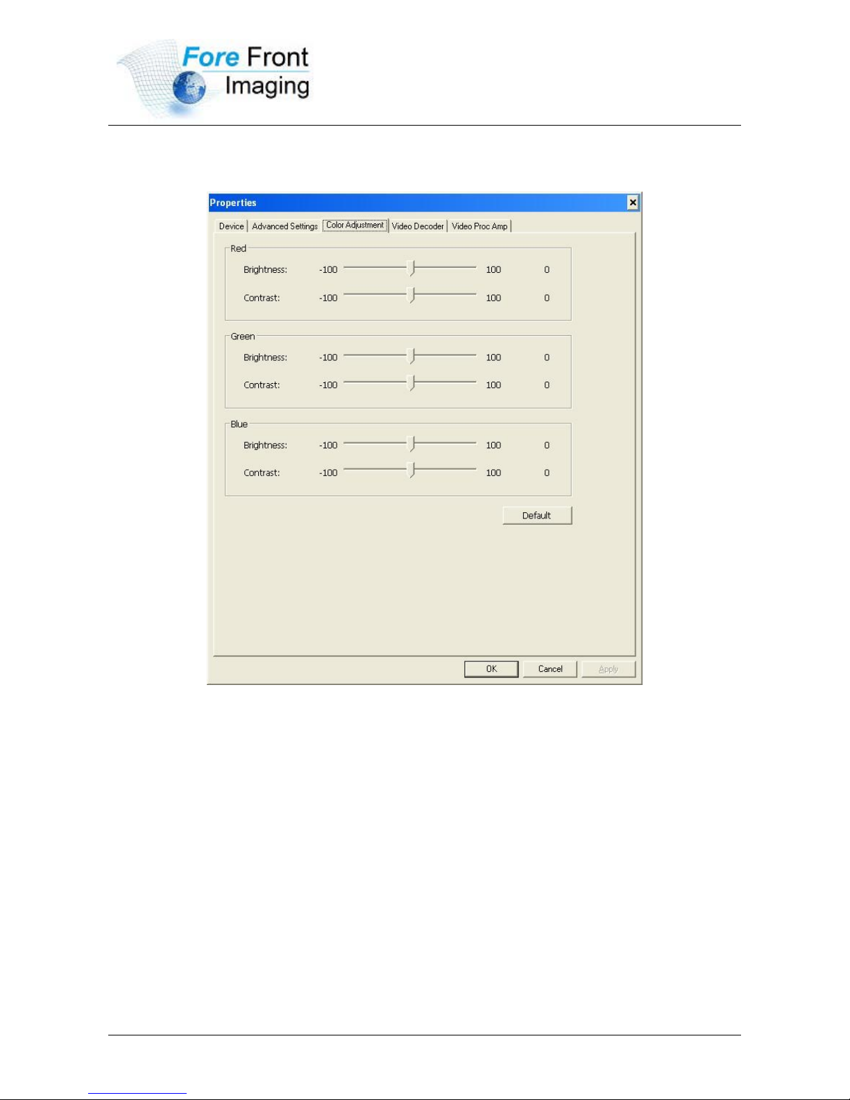
9.4.1 "Color Adjustment" Instruction
Figure 12,HD device “Color Adjustment” properties page
Here can be adjusted R, G, B brightness and contrast separately, click "Default" to
restore default values.
10 Video Formats Setting
Driver is redefined "Filter Output Pin" interface and unified standard for SD and
HD. Output resolution can be any size, even special resolution which is cut.

10.1 Display "Filter Output Pin" In Common Software
AMCAP: Double click "AmCap.exe", choose HD video device "HD Video
(VC204XE Adapter1)" in "Devices" menu, then click “Video Capture Pin ...”in
"Settings" menu, pop-up " Filter Output Pin ".
10.2 “Out Format” Instruction
Figure 13,””properties page
Color Space: offer five color formats, YUYV, UYVY, I420, RGB 24 Bits, and RGB
32 Bits.
Image Size: set image size of output, it can be written manually, or select output
resolution from “Presets”, the bold font resolution at the top is the same as capture
image, it is the best resolution.
Frame Rate: set output frame rate, it can be written manually, or select from
“Presets”. If application software is set output frame rate, now setting is no effect,
when you open again, it will return frame rate in application software.
11 Audio Capture Device Instruction
VC 204XE is based on the Microsoft DirectShow interface. After installation in

operating system, the relevant audio devices will be added on. Any software which is
compatible with DirectSound, software with DirectShow can use the devices for
capturing sound, it is recorded voice which HDMI and analog line are mixed. Also
"Volume" and "Mute" in HDMI and analog line can be controlled independently.
11.1 Windows XP, Windows 2003
The name of audio capture device under Windows XP, Windows 2003:
Audio 1(VC204XE Adapter x)
Audio 2(VC204XE Adapter x)
Through system "Volume Control" to adjust recording volume, specific steps as
follows:
1. In system notification icon area on right corner double-click " " button to
pop-up " Open Volume Control" window.
2. Open "Options" menu, select "Properties" menu item.
3. In "Mixer", select "Audio 1(VC 204XE Adapter x)", click "OK" button.
4. Corresponding volume control project will be displayed, this time you can
operate volume and "quiet" according to your requirement.

Figure 14,Windows XP/2003“VolumeControl”-“Properties” dialogue
11.2 Windows Vista, Windows 7, Windows 2008, Windows 2008 R2
Under such operating systems, each capture card will show two audio capture devices:
HDMI In (VC204XE Adapter x)
Line In (VC 200XE Adapter x)
Through system "Volume Control" to adjust the recording volume, specific steps as
follows:
1. In system notification icon area on right corner right-click " "button, select
"Recording devices" in pop-up menu.
2. In pop-up list which displays recording device, select "HDMI In" or "Line In",
click "Properties" button, system will pop up device properties dialog window.
3. In Properties dialog box, select "Levels" property page, then you can operate
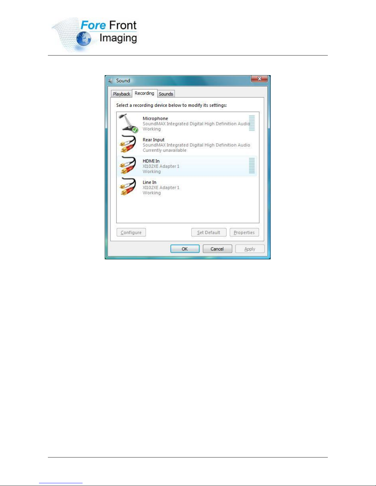
volume control and "Quiet" according to your requirement.
Figure 15, Windows Vista/7 recording device properties dialog windows
12 Compatible Software Instruction
VC204XE can be compatible with variety of audio and video capture software which
is based DirectShow interface, and audio capture software which is based
DirectSound interface, such as:
Windows Media Encoder
Adobe Flash Media Live Encoder
Real Producer Plus
VideoLAN for Windows
 Loading...