

Page 1
SECTION 412-04: Control Components 2002 F-150 Workshop Manual
Page
1
of 72002 F
-
150 Workshop Manual
6/2/2021
https://www.fordservicecontent.com/pubs/content/~WS21/~MUS~LEN/19/S21C4007.HTM
REMOVAL AND INSTALLATION
Procedure revision date: 06/14/2005
Temperature Blend Door Actuator
Removal
All vehicles
1. Depower the supplemental restraint system (SRS). For additional information, refer to Supplemental
Restraint System (SRS) Depowering and Repowering in Section 501-20B.
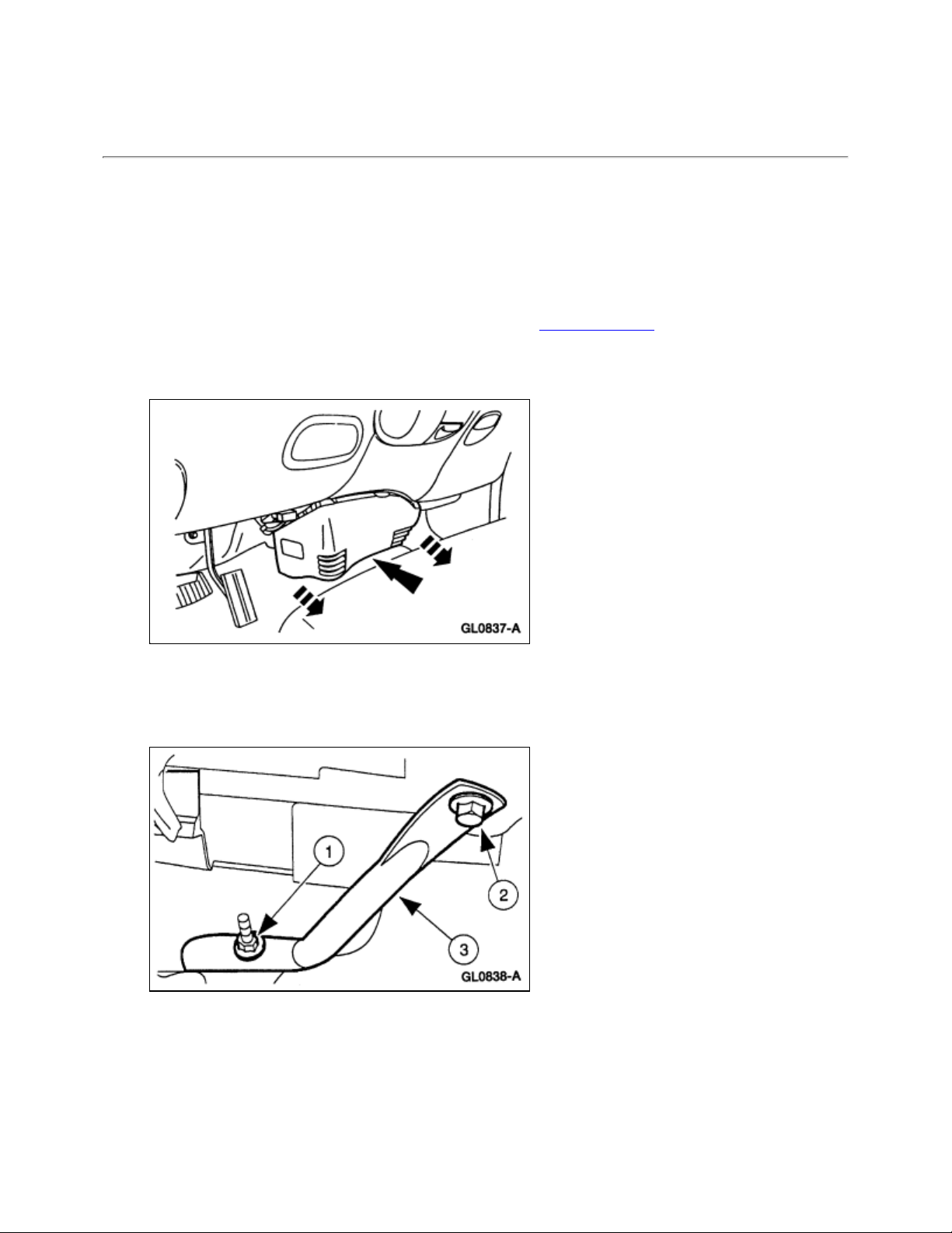
2. Remove the floor duct panel.
• Remove the pin-type retainers and release the expander clip.
3. Remove the RH instrument panel brace.
1. Remove the nut.
2. Remove the bolt.
3. Remove the brace.
4. Remove the LH instrument panel lower nut and position the brace aside.
Page 2

5. Disconnect the restraints control module (RCM) electrical connector.
Page
2
of 72002 F
-
150 Workshop Manual
6/2/2021
https://www.fordservicecontent.com/pubs/content/~WS21/~MUS~LEN/19/S21C4007.HTM
6. Remove the RCM and bracket assembly.
1. Remove the bracket retaining bolts.
2. Remove the RCM and bracket assembly.
Vehicles equipped with rear airflow duct
7. Cut the rear seat airflow duct along both sides.
• Fold back carpet.
• Cut rear seat airflow duct.
Page 3
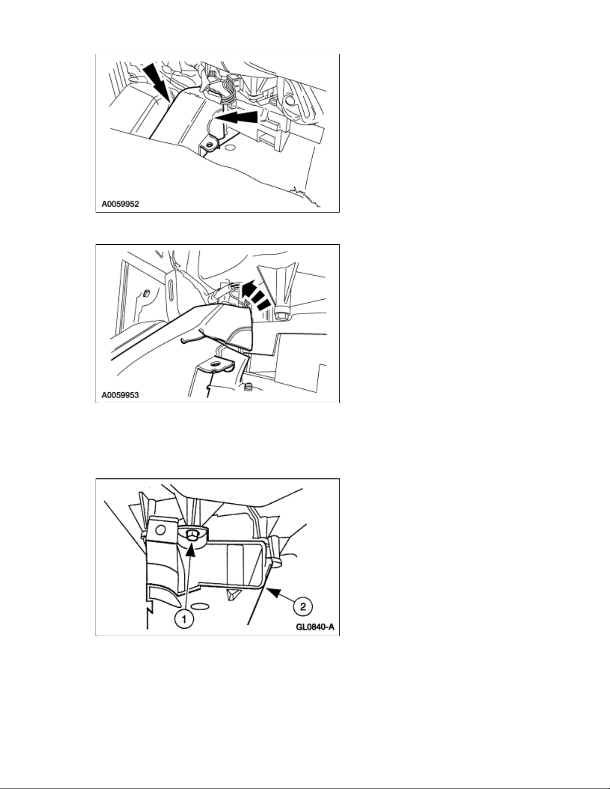
8. Fold the air duct rearwards.
Page
3
of 72002 F
-
150 Workshop Manual
6/2/2021
https://www.fordservicecontent.com/pubs/content/~WS21/~MUS~LEN/19/S21C4007.HTM
All vehicles
9. Remove the floor duct.
1. Remove the two screws (one each side).
2. Remove the floor duct.
10. Remove the electronic blend door actuator.
1. Disconnect the connector.
2. Remove the screws.
3. Pull down to release the actuator shaft and remove the electronic blend door actuator.
Page 4

Installation
Page
4
of 72002 F
-
150 Workshop Manual
6/2/2021
https://www.fordservicecontent.com/pubs/content/~WS21/~MUS~LEN/19/S21C4007.HTM
All vehicles
1. Install the electronic blend door actuator.
1. Connect the actuator shaft.
2. Install the screws.
3. Connect the connector.
2. Install the floor duct.
1. Install the floor duct.
2. Install the two screws (one each side).
Vehicles equipped with rear airflow duct
Page 5

3. Zip-tie the rear airflow duct to floor duct.
Page
5
of 72002 F
-
150 Workshop Manual
6/2/2021
https://www.fordservicecontent.com/pubs/content/~WS21/~MUS~LEN/19/S21C4007.HTM
4. Reposition the carpet.
All vehicles
WARNING: The tightening torque of the restraints control module (RCM) retaining bolts is
critical for correct system operation.
5. Install the RCM and bracket assembly.
6. Connect the restraints control module (RCM) electrical connector.
7. Install the LH instrument panel lower nut.
Page 6

8. Install the RH instrument panel brace.
Page
6
of 72002 F
-
150 Workshop Manual
6/2/2021
https://www.fordservicecontent.com/pubs/content/~WS21/~MUS~LEN/19/S21C4007.HTM
• Install the brace.
• Install the nut.
• Install the bolt.
9. Install the floor duct panel.
• Install the pin-type retainers and release the expander clip.
10. Repower the supplemental restraint system (SRS). For additional information, refer to Supplemental
Restraint System (SRS) Depowering and Repowering in Section 501-20B.
Page 7

Page
7
of 72002 F
-
150 Workshop Manual
6/2/2021
https://www.fordservicecontent.com/pubs/content/~WS21/~MUS~LEN/19/S21C4007.HTM
 Loading...