

Page 1
303-06-1 303-06-1Starting System
DIAGNOSIS AND TESTING
Starting System
Refer to Wiring Diagrams Cell 20, Starting System
for schematic and connector information.
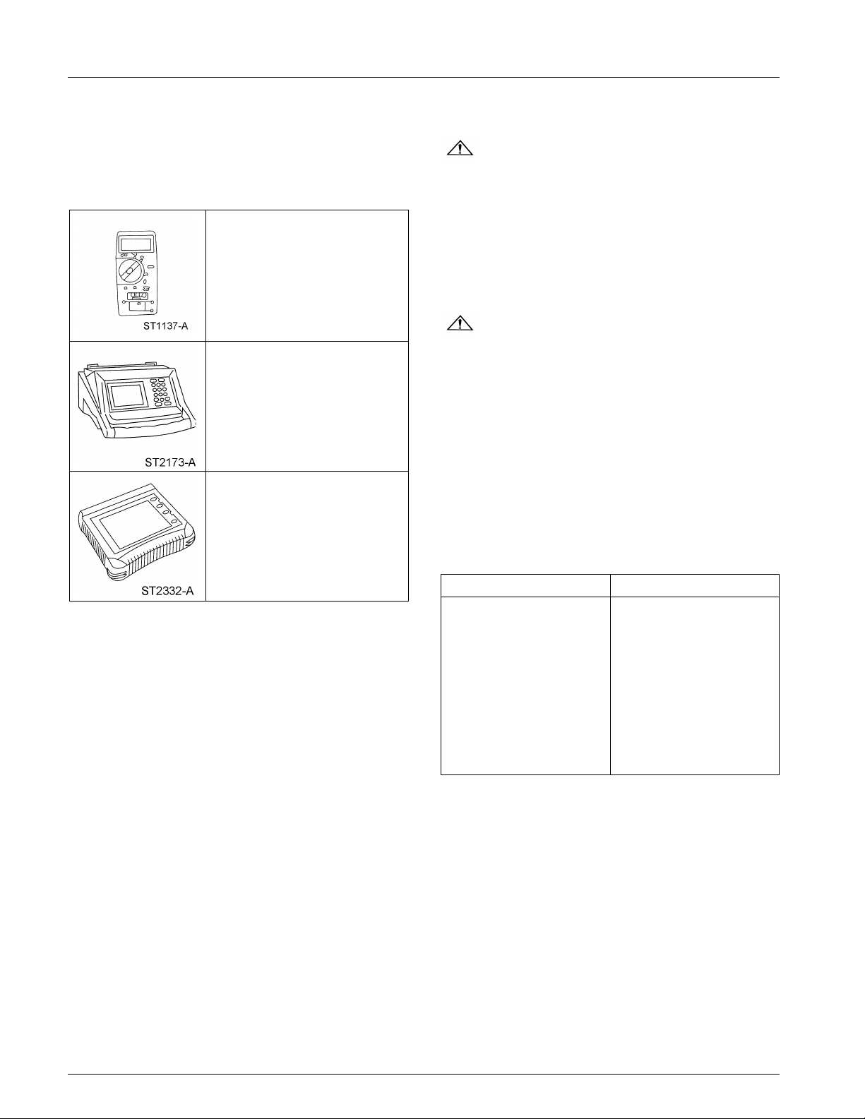
Special Tool(s)
73 Digital Multimeter
105-R0051 or equivalent
SABRE Premium Battery and
Electrical System Tester
010-00730 or equivalent
Worldwide Diagnostic System
(WDS)
Vehicle Communication Module
(VCM) with appropriate
adapters, or equivalent
diagnostic tool
Inspection and Verification
WARNING: When servicing the starter
motor or carrying out other underhood work in
the vicinity of the starter motor, be aware that
the heavy gauge battery input lead at the starter
solenoid is ‘‘electrically hot’’ at all times. A
protective cap or boot is provided over the
terminal of this lead and must be installed after
servicing. Failure to follow these instructions may
result in personal injury.
WARNING: When working in the area of
the starter motor, be careful to avoid touching
hot exhaust components. Failure to follow these
instructions may result in personal injury.
NOTE: When working on the starter system, make
sure the anti-theft system is deactivated, if equipped.
1. Verify the customer concern by operating the
starting system.
2. Visually inspect for obvious signs of
mechanical and electrical damage. Refer to the
following chart:
Visual Inspection Chart
Principles of Operation
The starting system is electronically controlled by
the passive anti-theft system (PATS). The PATS
recognizes the correct electronically coded ignition
key and signals the instrument cluster to provide a
ground for the starter relay. The energized relay
provides voltage to the starter solenoid with the key
in the START position, thereby allowing the starter
motor to activate.
Mechanical Electrical
• Starter motor • Battery
• Brackets • Smart junction box
(SJB) fuse:
— 21 (10A)
• Bussed electrical center
(BEC) fuse:
— 3 (30A)
• Anti-theft system
• Damaged wiring harness
• Loose or corroded
connections
3. If an obvious cause for an observed or reported
concern is found, correct the cause (if possible)
before proceeding to the next step.
4. If the cause is not visually evident, connect the
diagnostic tool to the data link connector (DLC)
and select the vehicle to be tested from the
diagnostic tool menu. If the diagnostic tool does
not communicate with the vehicle:
• check that the program card is correctly
installed.
• check the connections to the vehicle.
• check the ignition switch position.
Copyright 2004, Ford Motor Company
Last updated: 12/8/2004
2005 Mustang, 12/2004
Page 2

303-06-2 303-06-2Starting System
DIAGNOSIS AND TESTING (Continued)
5. If the diagnostic tool still does not communicate • System passed, retrieve and record the
with the vehicle, refer to the diagnostic tool continuous diagnostic trouble codes (DTCs),
operating manual. erase the continuous DTCs and carry out the
6. Carry out the diagnostic tool data link test. If
the diagnostic tool responds with: 7. If the DTCs retrieved are related to the concern,
• [appropriate communication networks, such
as SCP, ISO, UBP, CAN] circuit fault; all
electronic control units no response/not 8. If no DTCs related to the concern are retrieved,
equipped, refer to Section 418-00. GO to Symptom Chart.
• No response/not equipped for generic
electronic module (GEM), refer to Section
419-10.
Passive Anti-Theft System (PATS) — Diagnostic Trouble Code (DTC) Index
DTC Description Source Action
B1213 Anti-Theft Number Of Powertrain Control Module REFER to Section
Programmed Keys Is (PCM) 419-01B.
Below Minimum
B1342 ECU is Defective PCM CLEAR the DTCs.
B1600 Passive Anti-Theft System PCM REFER to Section
(PATS) Key Transponder 419-01B.
Is Not Received —
Damaged Key Or
Non-PATS Key
B1601 PATS Received Incorrect PCM REFER to Section
Key-Code From Key 419-01B.
Transponder
(Unprogrammed PATS
Key)
B1602 or B2431 PATS Received Invalid PCM REFER to Section
Format Of Key-Code From 419-01B.
Key Transponder (Partial
Key Read)
B1681 PATS Transceiver Module PCM REFER to Section
Signal Is Not Received 419-01B.
(Damaged, Not Connected
Or Damaged Wiring)
B2103 Internal Transceiver PCM REFER to Section
Antenna Damaged 419-01B.
P1260 PCM Disabled — Vehicle PCM REPAIR the PCM. REFER
Disabled to the Powertrain
self-test diagnostics for the GEM.
go to the Generic Electronic Module (GEM)
Diagnostic Trouble Code (DTC) Index.
REPEAT the self-test. If
DTC B1342 is retrieved
again, INSTALL a PCM.
REFER to Section 303-14.
CLEAR the DTCs.
REPEAT the self-test.
Control/Emissions
Diagnosis (PC/ED) manual.
2005 Mustang, 12/2004
Page 3

303-06-3 303-06-3Starting System
DIAGNOSIS AND TESTING (Continued)
Symptom Chart
Symptom Chart
Condition Possible Sources Action
• The engine does not crank • Battery • GO to Pinpoint Test A.
and the relay does not click • Fuse
• Starter relay
• Ignition switch
• Digital transmission range
(TR) sensor (automatic
transmission only)
• Clutch pedal position (CPP)
switch (manual transmission
only)
• Circuit
• The engine does not crank • Fuse • GO to Pinpoint Test B.
and the relay does click • Battery
• Starter motor/solenoid
• Ignition switch
• Circuit
• The engine cranks slowly • Battery • GO to Pinpoint Test C.
• Starter motor/solenoid
• Circuit
• Unusual starter noise • Starter mounting • GO to Pinpoint Test D.
• Flexplate or flywheel
• Starter motor
• The starter spins but the • Starter motor • INSPECT the starter motor
engine does not crank • Damaged flexplate or mounting and engagement.
flywheel ring gear teeth INSTALL a new starter
motor. REFER to Starter
Motor — 4.0L SOHC or
Starter Motor — 4.6L (3V) in
this section.
• INSPECT the flexplate or
flywheel for damaged,
missing or worn teeth.
REPAIR as required.
Pinpoint Tests
Pinpoint Test A: The Engine Does Not Crank
And The Relay Does Not Click
Normal Operation
In normal operation, voltage from the bussed
electrical center (BEC) is supplied to the ignition
switch through circuit 1050 (LG/PK). When the
ignition switch is placed in the START position,
voltage is supplied through circuit 1522 (DG) to the
smart junction box (SJB).
For automatic transmission equipped vehicles,
voltage is supplied from the SJB to the digital
transmission range (TR) sensor through circuit 32
(RD/LB). In PARK or NEUTRAL, voltage is
supplied from the TR sensor through circuit 33
(WH/PK) to the starter relay coil located in the
BEC. The starter relay coil is supplied ground from
the PCM through circuit 1419 (LG/YE).
For manual transmission equipped vehicles, voltage
from the SJB is supplied to the clutch pedal position
switch (CPP) through circuit 32 (RD/LB). When the
clutch pedal is depressed, voltage is supplied from
the CPP to the starter relay coil located in the BEC
through circuit 32 (RD/LB). The starter relay coil is
supplied ground from the PCM through circuit 1419
(LG/YE).
2005 Mustang, 12/2004
Page 4
303-06-4 303-06-4Starting System
DIAGNOSIS AND TESTING (Continued)
When the starter relay is energized, voltage supplied
to the relay switch is sent to the starter motor
solenoid through circuit 113 (YE/LB). Battery
voltage is supplied to the starter motor through
Possible Causes
• Fuse(s)
• An open in battery voltage feed BEC, 2037 (RD)
circuit 2037 (RD) at all times.
• Starter motor relay
• Starter
PINPOINT TEST A: THE ENGINE DOES NOT CRANK AND THE RELAY DOES NOT CLICK
Test Step Result / Action to Take
A1 CHECK THE BATTERY
• Check the battery condition and charge if necessary. Refer to
Section 414-01. GO to A2.
• Is the battery OK?
A2 CHECK FOR PATS DTCS
• NOTE: The PATS DTCs are the only DTCs of concern in this
step. Only repair retrieved non-PATS DTCs if a customer GO to Section 419-01B to diagnose the
concern is reported. PATS DTCs.
Check for PATS DTCs.
• Were any PATS DTCs retrieved?
A3 CHECK CIRCUIT 33 (WH/PK) (CIRCUIT 32 [RD/LB] MANUAL
TRANSMISSION ONLY) FOR VOLTAGE
• Disconnect: Starter Motor Relay.
• Key in START position.
• If equipped, fully depress the clutch pedal.
or 113 (YE/LB)
Yes
No
CHARGE or INSTALL a new battery as
necessary. REFER to Section 414-01.
TEST the system for normal operation.
Yes
No
GO to A3.
(Continued)
2005 Mustang, 12/2004
Page 5
303-06-5 303-06-5Starting System
DIAGNOSIS AND TESTING (Continued)
PINPOINT TEST A: THE ENGINE DOES NOT CRANK AND THE RELAY DOES NOT CLICK (Continued)
Test Step Result / Action to Take
A3 CHECK CIRCUIT 33 (WH/PK) (CIRCUIT 32 [RD/LB] MANUAL
TRANSMISSION ONLY) FOR VOLTAGE (Continued)
• Measure the voltage between starter motor relay C1017-85,
circuit 33 (WH/PK) (circuit 32 [RD/LB] manual transmission only)
and ground while holding the key in the START position and
with the clutch pedal, if equipped, fully depressed.
• Is the voltage greater than 10 volts? to A7.
A4 CHECK CIRCUIT 32 (RD/LB) FOR VOLTAGE AT THE DIGITAL
TR SENSOR (AUTOMATIC TRANSMISSION ONLY)
• Key in OFF position.
• Disconnect: Digital TR Sensor C167.
• Key in START position.
Yes
GO to A12.
No
Vehicles equipped with an automatic
transmission, GO to A4. Vehicles
equipped with a manual transmission, GO
(Continued)
2005 Mustang, 12/2004
Page 6
303-06-6 303-06-6Starting System
DIAGNOSIS AND TESTING (Continued)
PINPOINT TEST A: THE ENGINE DOES NOT CRANK AND THE RELAY DOES NOT CLICK (Continued)
Test Step Result / Action to Take
A4 CHECK CIRCUIT 32 (RD/LB) FOR VOLTAGE AT THE DIGITAL
TR SENSOR (AUTOMATIC TRANSMISSION ONLY) (Continued)
• Measure the voltage between digital TR sensor C167-10, circuit
32 (RD/LB) and ground while holding the key in the START
position.
Yes
GO to A5.
• Is the voltage greater than 10 volts? GO to A8.
A5 CHECK CIRCUIT 33 (WH/PK) FOR AN OPEN
• Key in OFF position.
• Measure the resistance between digital TR sensor C167-12,
circuit 33 (WH/PK) and starter motor relay C1017-85, circuit 33
(WH/PK).
No
Yes
GO to A6.
No
REPAIR circuit 33 (WH/PK). TEST the
• Is the resistance less than 5 ohms? system for normal operation.
2005 Mustang, 12/2004
(Continued)
Page 7
303-06-7 303-06-7Starting System
DIAGNOSIS AND TESTING (Continued)
PINPOINT TEST A: THE ENGINE DOES NOT CRANK AND THE RELAY DOES NOT CLICK (Continued)
Test Step Result / Action to Take
A6 CHECK DIGITAL TR SENSOR ADJUSTMENT
• Carry out the digital TR sensor adjustment. Refer to Section
307-01. INSTALL a new digital TR sensor. TEST
• Is the digital TR sensor adjusted correctly? the system for normal operation.
A7 CHECK CIRCUIT 32 (RD/LB) FOR VOLTAGE AT THE CLUTCH
PEDAL POSITION (CPP) SWITCH
• Key in OFF position.
• Disconnect: CPP Switch C257.
• Key in START position.
• Measure the voltage between CPP switch C257-1, circuit 32
(RD/LB) and ground while holding the key in the START
position.
Yes
No
ADJUST the digital TR sensor as
necessary. TEST the system for normal
operation.
• Is the voltage greater than 10 volts? GO to A8.
A8 CHECK CIRCUIT 1522 (DG) FOR AN OPEN
• Key in OFF position.
• Disconnect: SJB Fuse 21.
• Key in START position.
• Measure the voltage between SJB fuse 21, circuit 1522 (DG)
and ground while holding the key in the START position.
• Is the voltage greater than 10 volts? GO to A9.
A9 CHECK CIRCUIT 1050 (LG/PK) FOR VOLTAGE
• Key in OFF position.
• Disconnect: Ignition Switch C250.
Yes
GO to A11.
No
Yes
REPAIR circuit 32 (RD/LB). TEST the
system for normal operation.
No
(Continued)
2005 Mustang, 12/2004
Page 8

303-06-8 303-06-8Starting System
DIAGNOSIS AND TESTING (Continued)
PINPOINT TEST A: THE ENGINE DOES NOT CRANK AND THE RELAY DOES NOT CLICK (Continued)
Test Step Result / Action to Take
A9 CHECK CIRCUIT 1050 (LG/PK) FOR VOLTAGE (Continued)
• Measure the voltage between ignition switch C250-4, circuit
1050 (LG/PK) and ground.
Yes
GO to A10.
No
• Is the voltage greater than 10 volts? system for normal operation.
A10 CHECK CIRCUIT 1522 (DG) FOR AN OPEN
• Measure the resistance between ignition switch C250-7, circuit
1522 (DG) and SJB fuse 21. INSTALL a new ignition switch. REFER to
• Is the resistance less than 5 ohms? Section 211-05. TEST the system for
A11 CHECK CIRCUIT 32 (RD/LB) FOR AN OPEN
• Key in OFF position.
REPAIR circuit 1050 (LG/PK). TEST the
Yes
normal operation.
No
REPAIR circuit 1522 (DG). TEST the
system for normal operation.
(Continued)
2005 Mustang, 12/2004
Page 9

303-06-9 303-06-9Starting System
DIAGNOSIS AND TESTING (Continued)
PINPOINT TEST A: THE ENGINE DOES NOT CRANK AND THE RELAY DOES NOT CLICK (Continued)
Test Step Result / Action to Take
A11 CHECK CIRCUIT 32 (RD/LB) FOR AN OPEN (Continued)
• Measure the resistance between CPP switch C257-2, circuit 32
(RD/LB) and starter motor relay C1017-85, circuit 32 (RD/LB).
Yes
INSTALL a new CPP switch. REFER to
Section 303-14. TEST the system for
normal operation.
No
REPAIR circuit 32 (RD/LB). TEST the
• Is the resistance less than 5 ohms? system for normal operation.
A12 CHECK THE STARTER MOTOR RELAY GROUND CIRCUIT FOR
AN OPEN
• Key in START position.
(Continued)
2005 Mustang, 12/2004
Page 10
303-06-10 303-06-10Starting System
DIAGNOSIS AND TESTING (Continued)
PINPOINT TEST A: THE ENGINE DOES NOT CRANK AND THE RELAY DOES NOT CLICK (Continued)
Test Step Result / Action to Take
A12 CHECK THE STARTER MOTOR RELAY GROUND CIRCUIT FOR
AN OPEN (Continued)
• Measure the voltage between starter motor relay C1017-86,
circuit 1419 (LG/YE) and starter motor relay C1017-85, circuit 33
(WH/PK) (circuit 32 [RD/LB] manual transmission only) while
holding the key in the START position and clutch pedal, if
equipped, fully depressed.
• Is the voltage greater than 10 volts? GO to A13.
A13 CHECK CIRCUIT 1419 (LG/YE) FOR AN OPEN
• Key in OFF position.
• Disconnect: PCM C175B.
Yes
INSTALL a new starter motor relay. TEST
the system for normal operation.
No
(Continued)
2005 Mustang, 12/2004
Page 11

303-06-11 303-06-11Starting System
DIAGNOSIS AND TESTING (Continued)
PINPOINT TEST A: THE ENGINE DOES NOT CRANK AND THE RELAY DOES NOT CLICK (Continued)
Test Step Result / Action to Take
A13 CHECK CIRCUIT 1419 (LG/YE) FOR AN OPEN (Continued)
• Measure the resistance between PCM C175B-2, circuit 1419
(LG/YE) and starter relay C1017-86, circuit 1419 (LG/YE).
Yes
INSTALL a new PCM. REFER to Section
303-14. TEST the system for normal
operation.
No
• Is the resistance less than 5 ohms? system for normal operation.
Pinpoint Test B: The Engine Does Not Crank
And The Relay Does Click
Normal Operation
In normal operation, voltage from the bussed
electrical center (BEC) is supplied to the ignition
switch through circuit 1050 (LG/PK). When the
ignition switch is placed in the START position,
voltage is supplied through circuit 1522 (DG) to the
smart junction box (SJB).
For automatic transmission equipped vehicles,
voltage is supplied from the SJB to the digital
transmission range (TR) sensor through circuit 32
(RD/LB). In PARK or NEUTRAL, voltage is
For manual transmission equipped vehicles, voltage
from the SJB is supplied to the clutch pedal position
switch (CPP) through circuit 32 (RD/LB). When the
clutch pedal is depressed, voltage is supplied from
the CPP to the starter relay coil located in the BEC
through circuit 32 (RD/LB). The starter relay coil is
supplied ground from the PCM through circuit 1419
(LG/YE).
When the starter relay is energized, voltage supplied
to the relay switch is sent to the starter motor
solenoid through circuit 113 (YE/LB). Battery
voltage is supplied to the starter motor through
circuit 2037 (RD) at all times.
REPAIR circuit 1419 (LG/YE). TEST the
supplied from the TR sensor through circuit 33 Possible Causes
(WH/PK) to the starter relay coil located in the
BEC. The starter relay coil is supplied ground from
the PCM through circuit 1419 (LG/YE).
• Fuse(s)
• An open in circuit 1050 (LG/PK), 1522 (DG), 32
(RD/LB), 33 (WH/PK) or 1419 (LG/YE)
• Powertrain control module (PCM)
2005 Mustang, 12/2004
Page 12

303-06-12 303-06-12Starting System
DIAGNOSIS AND TESTING (Continued)
• Digital transmission range (TR) switch
• Ignition switch
• Starter motor relay
• Clutch pedal position (CPP) switch
PINPOINT TEST B: THE ENGINE DOES NOT CRANK AND THE RELAY DOES CLICK
Test Step Result / Action to Take
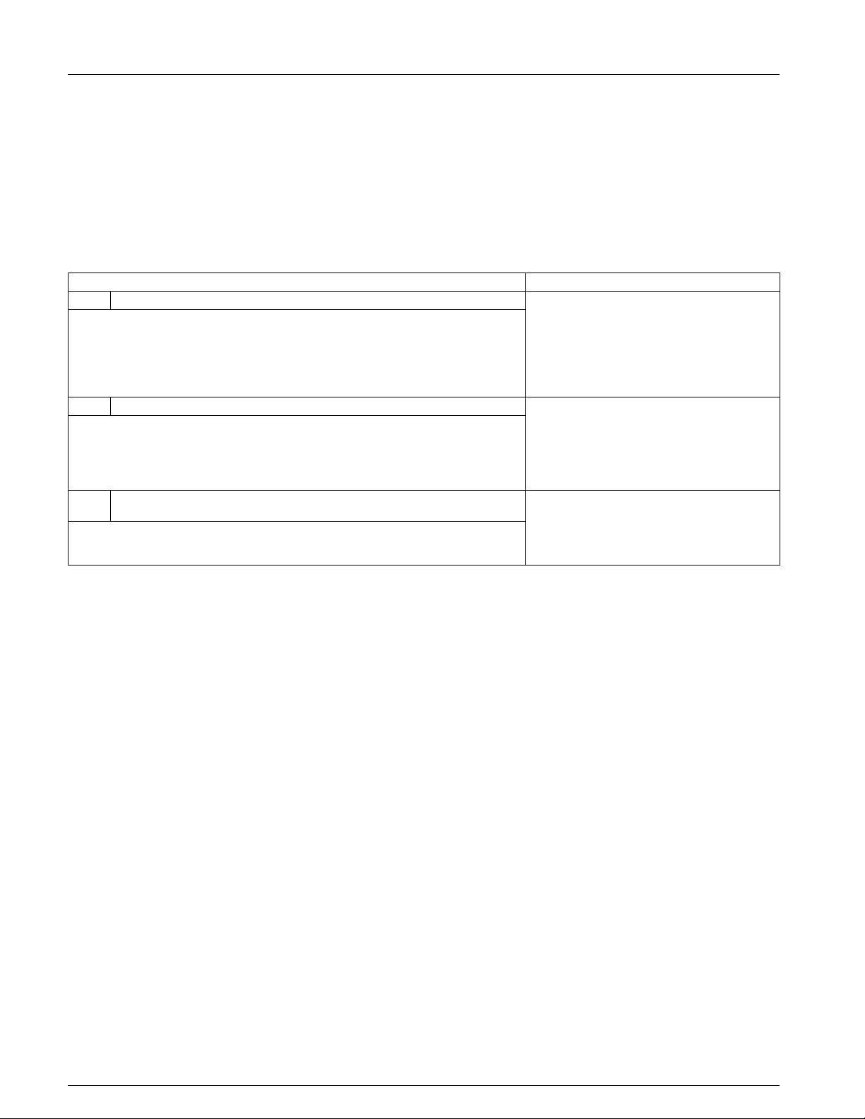
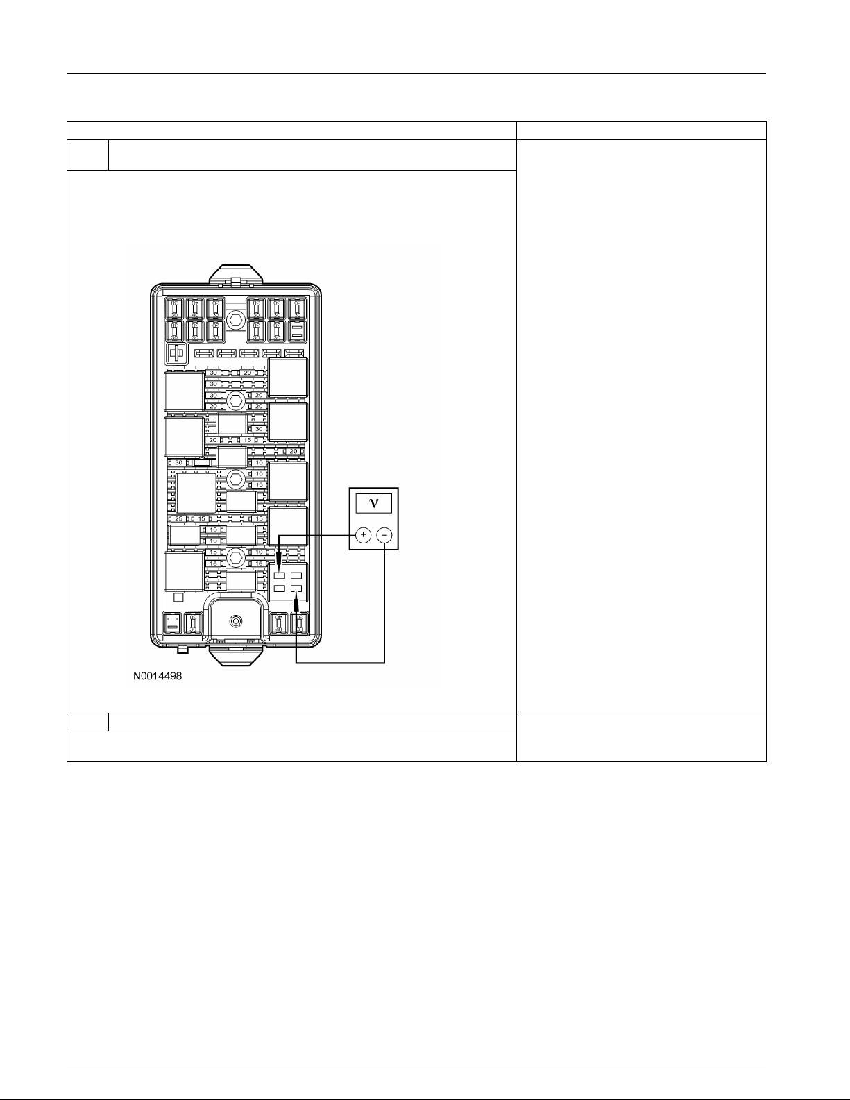
B1 CHECK THE VOLTAGE TO THE STARTER RELAY
• Measure the voltage between starter relay C1017-30 and
ground.
Yes
GO to B2.
No
INSTALL a new bussed electrical center
(BEC). TEST the system for normal
• Is the voltage greater than 10 volts? operation.
(Continued)
2005 Mustang, 12/2004
Page 13

303-06-13 303-06-13Starting System
DIAGNOSIS AND TESTING (Continued)
PINPOINT TEST B: THE ENGINE DOES NOT CRANK AND THE RELAY DOES CLICK (Continued)
Test Step Result / Action to Take
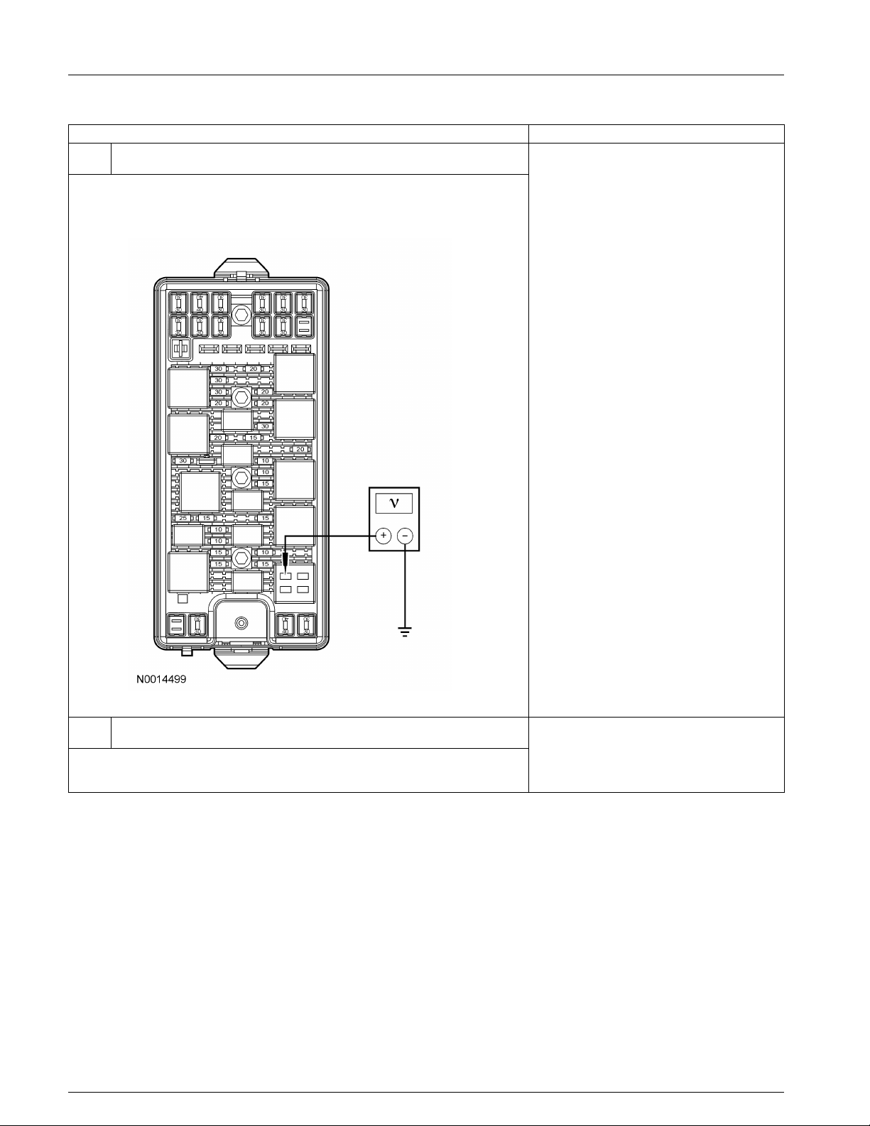
B2 CHECK THE VOLTAGE TO THE STARTER MOTOR SOLENOID
• Measure the voltage between starter motor solenoid positive
terminal and ground.
Yes
GO to B3.
No
• Is the voltage 10 volts or greater? TEST the system for normal operation.
B3 MANUALLY JUMP THE STARTER MOTOR
• Connect one end of a fused (15A) jumper wire to the positive
terminal of the battery and touch the other end to the starter
solenoid S-terminal.
REPAIR circuit 2037 (RD) for an open.
• Does the starter solenoid engage? the system for normal operation.
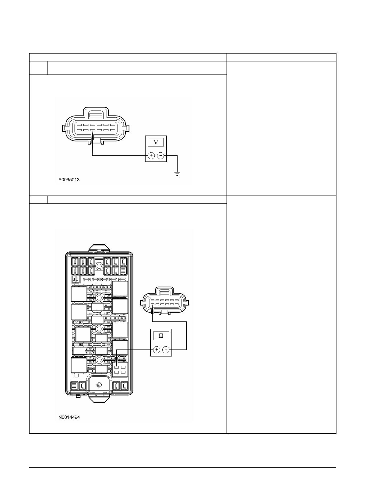
B4 TEST THE STARTER MOTOR RELAY
• Carry out the relay component test on the starter motor relay.
Refer to Wiring Diagrams Cell 149 for component testing. REPAIR circuit 113 (YE/LB) for an open.
• Does the starter motor relay test good? TEST the system for normal operation.
Pinpoint Test C: The Engine Cranks Slowly
Normal Operation
In normal operation, voltage from the bussed
electrical center (BEC) is supplied to the ignition
switch through circuit 1050 (LG/PK). When the
ignition switch is placed in the START position,
voltage is supplied through circuit 1522 (DG) to the
smart junction box (SJB).
Yes
GO to B4.
No
INSTALL a new starter motor. REFER to
Starter Motor — 4.0L SOHC or Starter
Motor — 4.6L (3V) in this section. TEST
Yes
No
INSTALL a new starter motor relay. TEST
the system for normal operation.
For automatic transmission equipped vehicles,
voltage is supplied from the SJB to the digital
transmission range (TR) sensor through circuit 32
(RD/LB). In PARK or NEUTRAL, voltage is
supplied from the TR sensor through circuit 33
(WH/PK) to the starter relay coil located in the
BEC. The starter relay coil is supplied ground from
the PCM through circuit 1419 (LG/YE).
2005 Mustang, 12/2004
Page 14

303-06-14 303-06-14Starting System
DIAGNOSIS AND TESTING (Continued)
For manual transmission equipped vehicles, voltage
from the SJB is supplied to the clutch pedal position
switch (CPP) through circuit 32 (RD/LB). When the
clutch pedal is depressed, voltage is supplied from
the CPP to the starter relay coil located in the BEC
through circuit 32 (RD/LB). The starter relay coil is
supplied ground from the PCM through circuit 1419
(LG/YE).
When the starter relay is energized, voltage supplied
to the relay switch is sent to the starter motor
solenoid through circuit 113 (YE/LB). Battery
voltage is supplied to the starter motor through
circuit 2037 (RD) at all times.
PINPOINT TEST C: THE ENGINE CRANKS SLOWLY
Test Step Result / Action to Take
C1 CHECK THE VOLTAGE TO THE STARTER
• Key in OFF position.
• Measure the voltage between starter motor solenoid positive
terminal and ground.
Possible Causes
• Fuse(s)
• Circuit 2037 (RD)
• Ground circuit
• Starter motor
• Is the voltage 12.5 volts or greater? operation.
C2 CHECK MOTOR GROUND CIRCUIT
• Carry out the Motor Ground Circuit test. Refer to Component
Tests in this section. INSTALL a new starter motor. TEST the
• Is the ground OK? system for normal operation.
Pinpoint Test D: Unusual Starter Noise
Normal Operation
In normal operation, voltage from the bussed
electrical center (BEC) is supplied to the ignition
switch through circuit 1050 (LG/PK). When the
ignition switch is placed in the START position,
voltage is supplied through circuit 1522 (DG) to the
smart junction box (SJB).
Yes
GO to C2.
No
REPAIR circuit 2037 (RD). CLEAN and
TIGHTEN the connections at the battery
terminals. TEST the system for normal
Yes
No
REPAIR the ground circuit as necessary.
TEST the system for normal operation.
For automatic transmission equipped vehicles,
voltage is supplied from the SJB to the digital
transmission range (TR) sensor through circuit 32
(RD/LB). In PARK or NEUTRAL, voltage is
supplied from the TR sensor through circuit 33
(WH/PK) to the starter relay coil located in the
BEC. The starter relay coil is supplied ground from
the PCM through circuit 1419 (LG/YE).
2005 Mustang, 12/2004
Page 15

303-06-15 303-06-15Starting System
DIAGNOSIS AND TESTING (Continued)
For manual transmission equipped vehicles, voltage
from the SJB is supplied to the clutch pedal position
switch (CPP) through circuit 32 (RD/LB). When the
clutch pedal is depressed, voltage is supplied from
the CPP to the starter relay coil located in the BEC
through circuit 32 (RD/LB). The starter relay coil is
supplied ground from the PCM through circuit 1419
(LG/YE).
When the starter relay is energized, voltage supplied
to the relay switch is sent to the starter motor
solenoid through circuit 113 (YE/LB). Battery
voltage is supplied to the starter motor through
circuit 2037 (RD) at all times.
PINPOINT TEST D: UNUSUAL STARTER NOISE
Test Step Result / Action to Take
D1 CHECK THE STARTER MOTOR MOUNTING
• Inspect the starter motor mounting for cracks.
• Check the starter motor mounting bolts for looseness. GO to D2.
• Is the starter motor mounted correctly?
D2 INSPECT THE STARTER MOTOR
• Remove the starter motor. Refer to Starter Motor — 4.0L SOHC
or Starter Motor — 4.6L (3V) in this section. INSTALL a new starter motor. TEST the
• Inspect the starter motor for damage. system for normal operation.
• Is the starter motor damaged?
Possible Causes
• Starter motor mounting
• Starter motor mounting bolts
• Starter motor drive
• Flywheel or flexplate ring gear
• Starter motor
Yes
No
REINSTALL the starter motor correctly.
REFER to Starter Motor — 4.0L SOHC or
Starter Motor — 4.6L (3V) in this section.
Yes
No
CHECK the starter drive. REFER to
Component Tests, Starter Drive Test in
this section. INSTALL a new starter motor.
TEST the system for normal operation.
Component Tests
Starter Motor — Load Test
WARNING: When servicing the starter
motor or carrying out other underhood work in
the vicinity of the starter motor, be aware that
the heavy gauge battery input lead at the starter
solenoid is ‘‘electrically hot’’ at all times.
CAUTION: A protective cap or boot is
provided over the battery input terminal on all
car lines and must be installed after repair. Be
sure to disconnect the battery ground cable
before repairing the starter motor.
1. Before carrying out this test inspection, check
the battery to determine its state of charge.
Carry out a load test of the battery using the
Starter, Alternator, Battery, Regulator and
Electrical Tester (SABRE). Refer to Section
414-00 for the test procedure.
2. Disconnect the ignition coil connector from the
ignition coil.
3. Connect the SABRE tester to the vehicle using
the amperage lead clipped around the positive
battery cable.
4. Measure the amperage of the starter motor
while activating the starting system.
5. A correctly operating starter motor will draw
from 130 to 190 amps of current.
Voltage Drop Tests
The following test procedures will be carried out
with the starter motor on the vehicle.
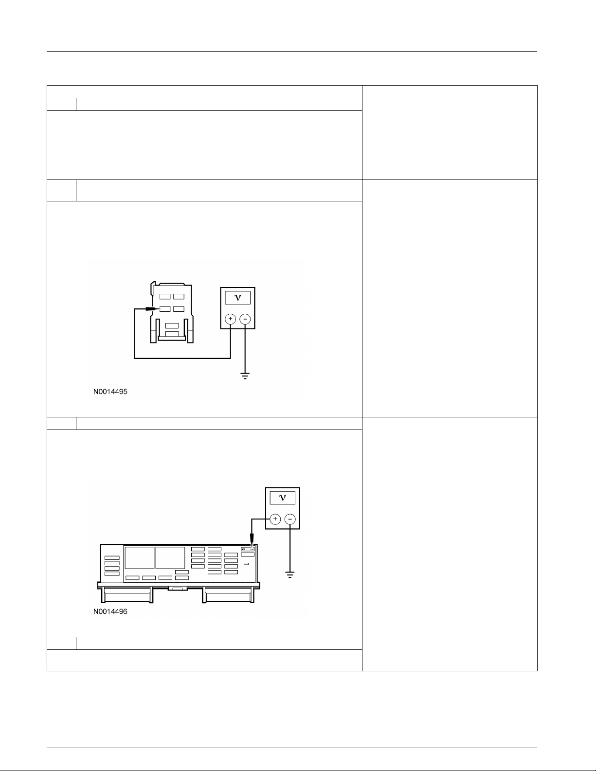
Motor Feed Circuit
NOTE: Make all multimeter connections at the
component terminal rather than the cable or wiring
terminal.
1. Disconnect the ignition coil connector from the
ignition coil.
2. Connect a remote starter switch between the
starter solenoid S-terminal and the battery
positive (+) post.
2005 Mustang, 12/2004
Page 16

303-06-16 303-06-16Starting System
DIAGNOSIS AND TESTING (Continued)
3. Connect the positive (+) lead of the 73 Digital 4. Engage the remote starter switch and read the
Multimeter to the battery positive (+) post. voltage. The reading should be 0.2 volt or less.
Connect the negative (-) lead of the multimeter
to the starter solenoid M-terminal.
4. Engage the remote starter switch. The at the battery and chassis. Also, clean the
multimeter reading should be 0.5 volt or less. engine ground cable connection at the cable
5. If the voltage at the M-terminal is greater than
0.5 volt, move the multimeter negative (-) lead
to the starter solenoid B-terminal and repeat the
test.
6. If the voltage reading at the B-terminal is less
than 0.5 volt, the problem is either in the
connections at the starter solenoid or the starter
solenoid.
7. Remove the wires at the starter solenoid B-, Sand M-terminals. Clean the connections and
install the cables. Repeat Steps 1 through 5
above. If the reading is still higher than 0.5 volt
at the M-terminal and 0.5 volt or lower at the
B-terminal, the problem is in the starter
solenoid. Install a new starter motor. Refer to
Starter Motor — 4.0L SOHC or Starter Motor
— 4.6L (3V) in this section.
8. If the voltage taken at the starter solenoid
B-terminal is greater than 0.5 volt, the problem
is either the positive (+) battery cable
connection or the positive (+) battery cable.
Motor Ground Circuit
NOTE: Make all multimeter connections at the
component terminal rather than the cable or wiring
terminal.
A slow cranking condition can be caused by
resistance in the ground or return portion of the
cranking circuit. Check the voltage drop in the
ground circuit as follows:
1. Disconnect the ignition coil connector from the
ignition coil.
2. Connect a remote starter switch between the
starter solenoid S-terminal and the battery
positive (+) terminal.
3. Connect the positive (+) lead of a 73 Digital
Multimeter to the starter motor housing. The
connection must be clean and free of rust or
grease. Connect the negative (-) lead to the
negative (-) battery terminal.
5. If the voltage drop is greater than 0.2 volt,
clean the negative (-) battery cable connections
mounting bracket. If the voltage drop is still
excessive, repair or install a new battery
ground cable.
Starter Drive Test
1. Remove the starter motor. Refer to Starter
Motor — 4.0L SOHC or Starter Motor — 4.6L
(3V) in this section.
2. Secure the starter motor in a vise.
3. Connect the battery ground cable of a fully
charged battery to the case of the starter motor.
4. CAUTION: Do not leave the positive
lead of the battery connected to the starter
motor S-terminal for more than 10 seconds.
Touch the positive lead from the battery to the
S-terminal and verify that the starter drive
ejects.
5. Remove the positive lead from the starter
motor. The ejected starter drive should return to
its original position.
6. If the starter drive does not eject and return to
position, replace the starter motor.
7. Check the starter drive. It should turn freely in
one direction, and positively engage to the
armature when turned in the opposite direction.
If not as specified, install a new starter motor.
No Load Test
The starter No Load Test will identify open or
shorted windings and a possible rubbing starter
motor armature or bent starter motor armature shaft.
2005 Mustang, 12/2004
Page 17

303-06-17 303-06-17Starting System
DIAGNOSIS AND TESTING (Continued)
1. WARNING: Make sure that the starter
motor is securely mounted on a bench
because the starter motor may move or jump
when it is energized.
Connect a fully charged battery, a Starter,
Alternator, Battery, Regulator and Electrical
Tester (SABRE) and a remote starter switch to
the starter motor. Connect the remote starter
switch between the battery positive (+) post and
the starter motor S-terminal. Connect the
starter motor B-terminal to the battery positive
(+) post. Connect the SABRE positive (+)
terminal and negative (-) terminal to the
corresponding battery post. Make sure that the
battery and starter motor are grounded.
2. Engage the remote starter switch.
3. The starter motor should eject the starter drive
and run smoothly. If the starter motor does not
run smoothly, install a new starter motor.
4. While the starter motor is running, check the
voltmeter and ammeter.
5. The voltage should be greater than 11.0 volts
and the amperage should be no more than 70
amps.
6. If the voltage is lower than the 11.0 volts, or
the amperage is higher than 70 amps, install a
new starter motor.
2005 Mustang, 12/2004
 Loading...