

Page 1

Ford Sierra
Service and Repair Manual
Steve Rendle and Christopher Rogers
Models covered
Saloon (Sapphire and Hatchback), Estate and P100 Pick-up models, including special/limited editions,
with four-cylinder SOHC, DOHC & CVH petrol engines and two-wheel-drive
Does not cover V6 or Diesel engine models, four-wheel-drive models, or RS Cosworth
(903 - 368 - 11Y8)
© Haynes Publishing 1996
A book in the Haynes Service and Repair Manual Series
All rights reserved. No part of this book may be reproduced or
transmitted in any form or by any means, electronic or mechanical,
including photocopying, recording or by any information storage
or retrieval system, without permission in writing from the
copyright holder.
ISBN 1 85960 090 5
British Library Cataloguing in Publication Data
A catalogue record for this book is available from from the British library.
Printed by J H Haynes & Co. Ltd, Sparkford, Nr Yeovil,
Somerset BA22 7JJ
Haynes Publishing
Sparkford, Nr Yeovil, Somerset BA22 7JJ England
Haynes North America, Inc
861 Lawrence Drive, Newbury Park, California 91320 USA
Editions Haynes S.A.
147/149, rue Saint Honore, 75001 PARIS, France
Page 2

LIVING WITH YOUR FORD SIERRA
Introduction to the Ford Sierra Page 0•4
Acknowledgements Page 0•4
Safety first! Page 0•5
ROADSIDE REPAIRS
Jacking, vehicle support and wheel changing Page 0•6
Towing Page 0•7
Identifying leaks Page 0•8
Jump starting Page 0•9
Weekly Checks
Introduction Page 0•10
Underbonnet check points Page 0•10
Engine Oil level Page 0•12
Coolant level Page 0•12
Screen washer fluid level Page 0•13
Brake fluid level Page 0•13
Power steering fluid level Page 0•14
Electrical systems Page 0•14
Battery Page 0•15
Wiper blades Page 0•15
Tyre condition and pressure Page 0•16
Lubricants and fluids Page 0•17
Tyre pressures Page 0•18
MAINTENANCE
Routine Maintenance and Servicing Page 1•1
Maintenance schedule Page 1•4
Maintenance procedures Page 1•9
Contents
Page 3

REPAIRS AND OVERHAUL
Engine and Associated Systems
SOHC engines Page 2A•1
DOHC engines Page 2B•1
CVH engines Page 2C•1
Cooling, heating and air conditioning systems Page 3•1
Fuel/exhaust systems - carburettor models Page 4A•1
Fuel/exhaust systems - fuel injection models Page 4B•1
Engine electrical systems Page 5•1
TRANSMISSION
Clutch Page 6•1
Manual gearbox Page 7A•1
Automatic transmission Page 7B•1
Propellor shaft Page 8•1
Final drive and driveshafts Page 9•1
BRAKES AND SUSPENSION
Braking system Page 10•1
Suspension and steering Page 11•1
BODY EQUIPMENT
Bodywork, trim and fittings Page 12•1
Body electrical systems Page 13•1
Wiring Diagrams Page 13•22
Reference
General dimensions and weights Page REF•1
Buying spare parts and vehicle identification Page REF•3
General repair procedures Page REF•4
Tools and working facilities Page REF•5
MOT test checks Page REF•7
Fault finding Page REF•11
Glossary of technical terms Page REF•18
Index Page REF•23
Contents
Page 4
0•4
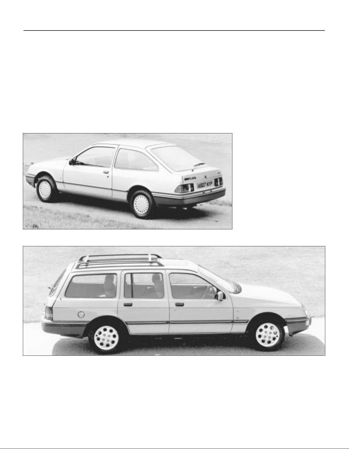
The Ford Sierra was first introduced in late 1982 with the option of
seven different engines and four different trim levels. This manual
covers the four cylinder in-line petrol engines, but other models in the
range are fitted with V6 or diesel engines.
The Sierra was introduced by Ford as the successor to the Cortina
and initially received a mixed reception as it was one of the first
vehicles to make use of the “aeroback” body style designed to reduce
the air drag coefficient to a minimum in the interests of fuel economy.
Mechanically the Sierra is similar to the Cortina with the exception of
all-round independent suspension.
Initially, 1.3, 1.6 and 2.0 litre SOHC carburettor engines were
available, with Hatchback and Estate body styles. In late 1984, a 1.8
litre SOHC engine became available and in 1985, a performance
orientated 2.0 litre SOHC fuel injection engine was introduced.
Towards the end of 1986, the 1.3 litre engine was phased out. In order
to fill a gap in the range, a Saloon body style, designated the Sapphire,
was introduced in early 1987 and shortly afterwards, a 1.8 litre CVH
engine replaced the previously used 1.8 litre SOHC engine throughout
the model range.
A 1.6 litre CVH engine was introduced in September 1991 to replace
the 1.6 litre SOHC engine used previously, this engine being broadly
similar to the original 1.8 litre CVH engine which was in turn uprated in
March, 1992.
A 2.0 litre DOHC (Double OverHead Camshaft) engine was introduced in August 1989 to replace the 2.0 litre SOHC engine.
In early 1988, a Sierra-based P100 pick-up model became available
to replace the previous Cortina-based design. The P100 consists of a
Sierra-type “cab” and front suspension, and a Ford Transit-type rear
suspension and 2.0 litre engine.
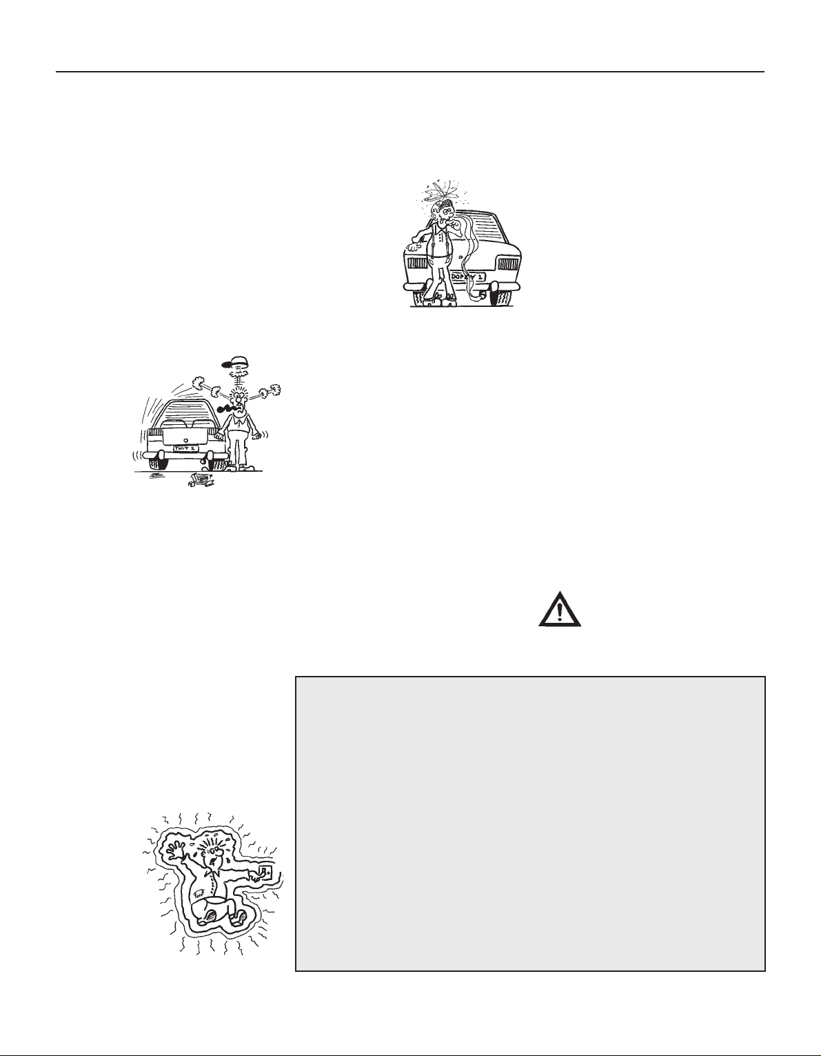
A wide range of standard and optional
equipment is available within the Sierra
range to suit most tastes, including an
anti-lock braking system.
For the home mechanic, the Sierra is a
straightforward vehicle to maintain and
repair since design features have been
incorporated to reduce the actual cost of
ownership to a minimum, and most of the
items requiring frequent attention are
easily accessible.
Ford Sierra L
Ford Sierra Ghia Estate
Introduction
We take great pride in the accuracy of information given in this
manual, but vehicle manufacturers make alterations and design
changes during the production run of a particular vehicle of which they
do not inform us. No liability can be accepted by the authors or
publishers for loss, damage or injury caused by errors in, or omissions
from, the information given.
Thanks are due to Champion Spark Plug who supplied the illustrations
showing spark plug conditions. Certain other illustrations are the
copyright of the Ford Motor Company and are used with their
permission. Thanks are also due to Sykes-Pickavant Limited, who
provided some of the workshop tools, and to all those people at
Sparkford who helped in the production of this manual.
Introduction to the Ford Sierra
Acknowledgements
Page 5
0•5
Safety First!
Working on your car can be dangerous.
This page shows just some of the potential
risks and hazards, with the aim of creating a
safety-conscious attitude.
General hazards
Scalding
• Don’t remove the radiator or expansion
tank cap while the engine is hot.
• Engine oil, automatic transmission fluid or
power steering fluid may also be dangerously
hot if the engine has recently been running.
Burning
• Beware of burns from the exhaust system
and from any part of the engine. Brake discs
and drums can also be extremely hot
immediately after use.
Crushing
• When working under or near
a raised vehicle,
always
supplement the
jack with axle
stands, or use
drive-on
ramps.
Never
venture
under a car which
is only supported by a jack.
• Take care if loosening or tightening hightorque nuts when the vehicle is on stands.
Initial loosening and final tightening should
be done with the wheels on the ground.
Fire
• Fuel is highly flammable; fuel vapour is
explosive.
• Don’t let fuel spill onto a hot engine.
• Do not smoke or allow naked lights
(including pilot lights) anywhere near a
vehicle being worked on. Also beware of
creating sparks
(electrically or by use of tools).
• Fuel vapour is heavier than air, so don’t
work on the fuel system with the vehicle over
an inspection pit.
• Another cause of fire is an electrical
overload or short-circuit. Take care when
repairing or modifying the vehicle wiring.
• Keep a fire extinguisher handy, of a type
suitable for use on fuel and electrical fires.
Electric shock
• Ignition HT
voltage can be
dangerous,
especially to
people with heart
problems or a
pacemaker. Don’t
work on or near the
ignition system with
the engine running or
the ignition switched on.
• Mains voltage is also dangerous. Make
sure that any mains-operated equipment is
correctly earthed. Mains power points should
be protected by a residual current device
(RCD) circuit breaker.
Fume or gas intoxication
• Exhaust fumes are
poisonous; they often
contain carbon
monoxide, which is
rapidly fatal if inhaled.
Never run the
engine in a
confined space
such as a garage
with the doors shut.
• Fuel vapour is also
poisonous, as are the vapours from some
cleaning solvents and paint thinners.
Poisonous or irritant substances
• Avoid skin contact with battery acid and
with any fuel, fluid or lubricant, especially
antifreeze, brake hydraulic fluid and Diesel
fuel. Don’t syphon them by mouth. If such a
substance is swallowed or gets into the eyes,
seek medical advice.
• Prolonged contact with used engine oil can
cause skin cancer. Wear gloves or use a
barrier cream if necessary. Change out of oilsoaked clothes and do not keep oily rags in
your pocket.
• Air conditioning refrigerant forms a
poisonous gas if exposed to a naked flame
(including a cigarette). It can also cause skin
burns on contact.
Asbestos
• Asbestos dust can cause cancer if inhaled
or swallowed. Asbestos may be found in
gaskets and in brake and clutch linings.
When dealing with such components it is
safest to assume that they contain asbestos.
Specia hazards
Hydrofluoric acid
• This extremely corrosive acid is formed
when certain types of synthetic rubber, found
in some O-rings, oil seals, fuel hoses etc, are
exposed to temperatures above 400
0
C. The
rubber changes into a charred or sticky
substance containing the acid. Once formed,
the acid remains dangerous for years. If it
gets onto the skin, it may be necessary to
amputate the limb concerned.
• When dealing with a vehicle which has
suffered a fire, or with components salvaged
from such a vehicle, wear protective gloves
and discard them after use.
The battery
• Batteries contain sulphuric acid, which
attacks clothing, eyes and skin. Take care
when topping-up or carrying the battery.
• The hydrogen gas given off by the battery
is highly explosive. Never cause a spark or
allow a naked light nearby. Be careful when
connecting and disconnecting battery
chargers or jump leads.
Air bags
• Air bags can cause injury if they go off
accidentally. Take care when removing the
steering wheel and/or facia. Special storage
instructions may apply.
Diesel injection equipment
• Diesel injection pumps supply fuel at very
high pressure. Take care when working on
the fuel injectors and fuel pipes.
Warning: Never expose the hands,
face or any other part of the body
to injector spray; the fuel can
penetrate the skin with potentially fatal
results.
Remember...
DO
• Do use eye protection when using power
tools, and when working under the vehicle.
• Do wear gloves or use barrier cream to
protect your hands when necessary.
• Do get someone to check periodically
that all is well when working alone on the
vehicle.
• Do keep loose clothing and long hair well
out of the way of moving mechanical parts.
• Do remove rings, wristwatch etc, before
working on the vehicle – especially the
electrical system.
• Do ensure that any lifting or jacking
equipment has a safe working load rating
adequate for the job.
A few tips
DON’T
• Don’t attempt to lift a heavy component
which may be beyond your capability – get
assistance.
• Don’t rush to finish a job, or take
unverified short cuts.
• Don’t use ill-fitting tools which may slip
and cause injury.
• Don’t leave tools or parts lying around
where someone can trip over them. Mop
up oil and fuel spills at once.
• Don’t allow children or pets to play in or
near a vehicle being worked on.
Page 6
0•6
The jack supplied with the vehicle tool kit
should only be used for changing roadwheels.
When carrying out any other kind of work,
raise the vehicle using a trolley jack, and
always supplement the jack with axle stands
positioned under the vehicle jacking points.
To change a roadwheel, first remove the
spare wheel and jack from their stowage
positions. On Saloon, Hatchback and Estate
models, the jack and spare wheel are located
in the luggage compartment. On P100
models, the jack is located behind the
passenger seat, and the spare wheel is
located under the rear of the cargo area.
Firmly apply the handbrake and engage first
gear on manual gearbox models or “P” on
automatic transmission models. Place chocks
at the front and rear of the wheel diagonally
opposite the one to be changed.
Where applicable, remove the wheel trim
and slacken the wheel nuts using the wheel
brace provided in the vehicle tool kit. Position
the jack head under the jacking point nearest
to the wheel to be changed. Raise the jack
until the wheel is clear of the ground, then
remove the wheel nuts and the wheel. Fit the
spare wheel and secure it with the wheel nuts.
Lower the jack until the wheel is just touching
the ground, and tighten the wheel nuts
moderately tight. Now lower the jack fully and
tighten the wheel nuts securely in a diagonal
sequence. Where applicable, refit the wheel
trim , then withdraw the jack and stow the
wheel and jack in thier respective locations.
When jacking up the vehicle with a trolley
jack, position the jack under one of the
relevant jacking point (note that on P100
models, the jackng points for use with a trolley
jack are different to those for use with the
vehicle jack). Do not jack the vehicle under the
sump or or any of the steering or suspension
components. Supplement the jack using axle
stands. The jacking points and axle stand
positions are shown in the accompanying
illustrations. Never work under , ar ound or near
a raised vehicle unless it is adequately
supported in at least two places.
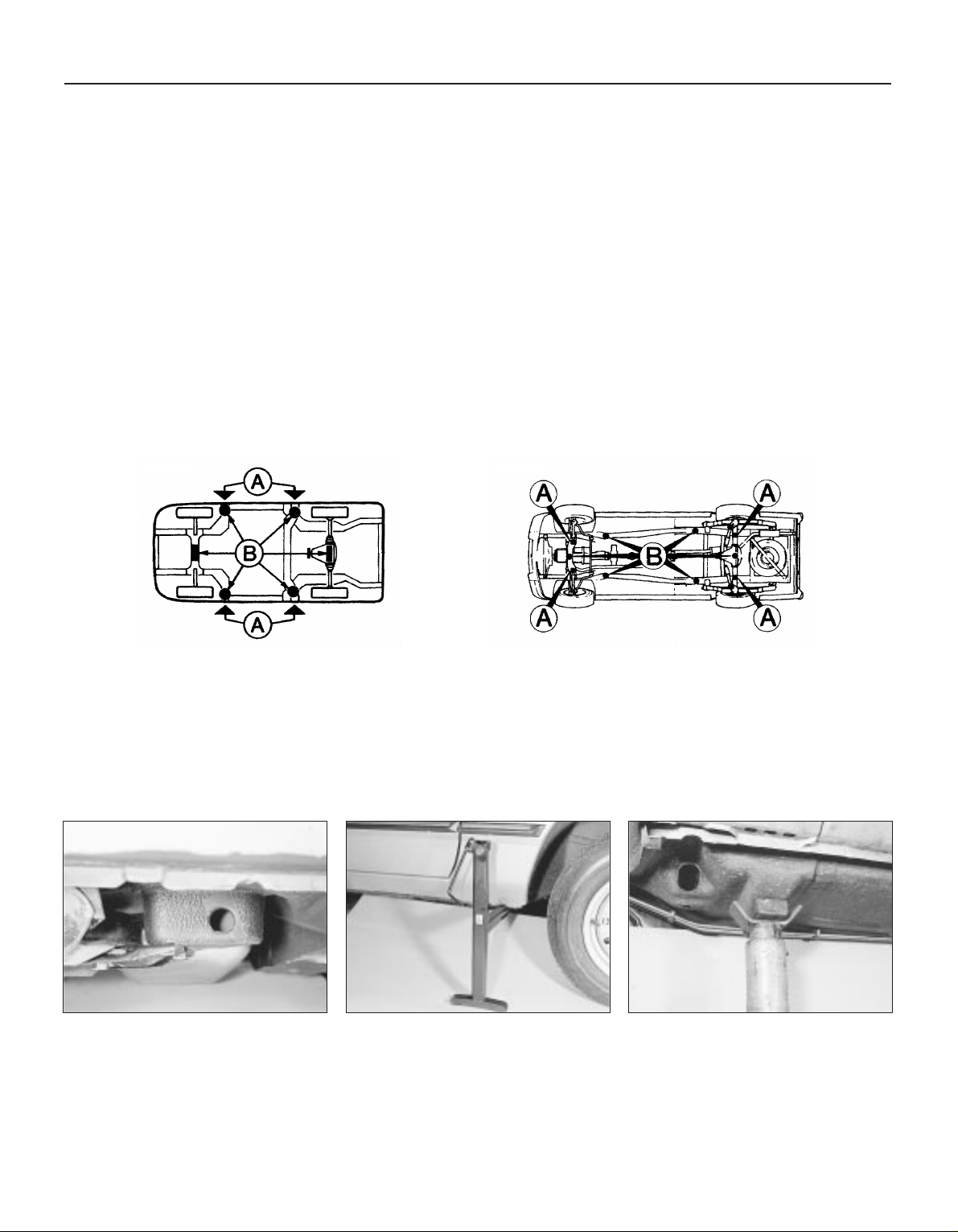
Jacking, vehicle support and wheel changing
Location of jacking points - Saloon,
Hatchback and Estate models
A Jacking points for use with vehicle jack
B Jacking points for use with trolley jack or
axle stands
Location of jacking points - P100 models
A Jacking points for use with vehicle jack
B Jacking points for use with trolley jack or axle stands
Rear jacking point - Hatchback model
Jack location by front wheel -
Hatchback model
Axle stand correctly positioned under
front jacking point -
Hatchback model
Roadside repairs
Page 7
0•7
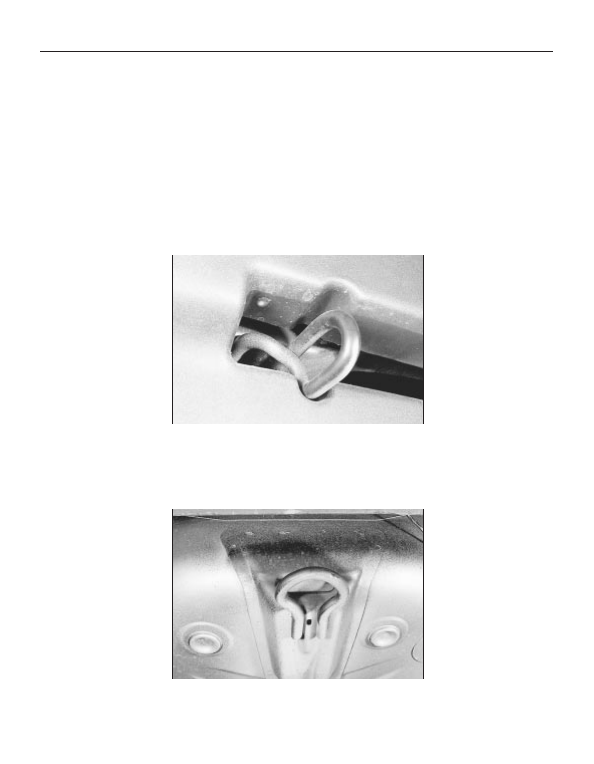
Rear towing eye - Hatchback model
Front towing eye - Hatchback model
Towing
Towing eyes are fitted to the front and rear
of the vehicle for attachment of a tow rope.
Always turn the ignition key to position “II”
when thew vehicle is being towed, so that the
steering lock is released and the direction
indicator and brake lamps are operational.
Before being towed, release the handbrake
and place the gear lever in neutral. On
automatic transmission models, the towing
speed must not exceed 25 mph (40 kph), and
the towing distance must not exceed 12 miles
(20 km). For longer distances, or if
transmission damage is suspected, the
propellor shaft should be removed, or the rear
of the vehicle should be lifted clear of the
ground.
Push or tow starting is not possible on
vehicles fitted with automatic transmission.
Roadside repairs
Page 8
0•8
Roadside repairs
Puddles on the garage floor or drive, or
obvious wetness under the bonnet or
underneath the car, suggest a leak that needs
investigating. It can sometimes be difficult to
decide where the leak is coming from,
especially if the engine bay is very dirty
already. Leaking oil or fluid can also be blown
rearwards by the passage of air under the car,
giving a false impression of where the
problem lies.
Warning: Most automotive oils
and fluids are poisonous. Wash
them off skin, and change out of
contaminated clothing, without
delay.
Identifying leaks
The smell of a fluid leaking
from the car may provide a
clue to what’s leaking. Some
fluids are distinctively
coloured. It may help to clean the car
carefully and to park it over some clean
paper overnight as an aid to locating the
source of the leak.
Remember that some leaks may only
occur while the engine is running.
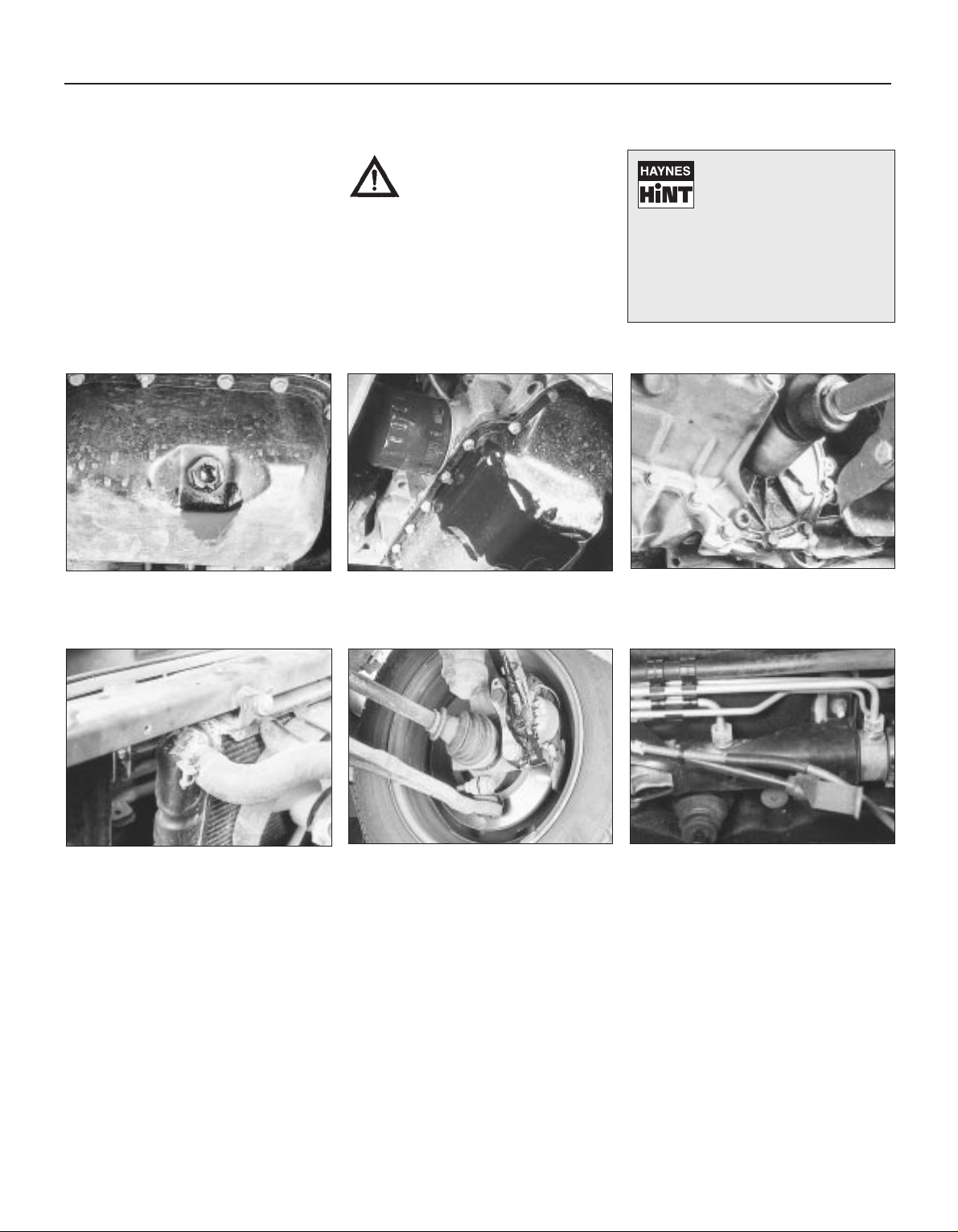
Sump oil Gearbox oil
Brake fluid Power steering fluid
Oil from filter
Antifreeze
Engine oil may leak from the drain plug... ...or from the base of the oil filter.
Leaking antifreeze often leaves a crystalline
deposit like this.
Gearbox oil can leak from the seals at the
inboard ends of the driveshafts.
A leak occurring at a wheel is almost
certainly brake fluid.
Power steering fluid may leak from the pipe
connectors on the steering rack.
Page 9
0•9
Roadside repairs
When jump-starting a car using a
booster battery, observe the following
precautions:
4 Before connecting the booster
battery, make sure that the ignition is
switched off.
4 Ensure that all electrical equipment
(lights, heater, wipers, etc) is
switched off.
4 Make sure that the booster battery is
the same voltage as the discharged
one in the vehicle.
4 If the battery is being jump-started
from the battery in another vehicle,
the two vehcles MUST NOT TOUCH
each other.
4 Make sure that the transmission is in
neutral (or PARK, in the case of
automatic transmission).
Jump starting will get you out
of trouble, but you must correct
whatever made the battery go
flat in the first place. There are
three possibilities:
1
The battery has been drained by
repeated attempts to start, or by
leaving the lights on.
2
The charging system is not working
properly (alternator drivebelt slack
or broken, alternator wiring fault or
alternator itself faulty).
3
The battery itself is at fault
(electrolyte low, or battery worn out).
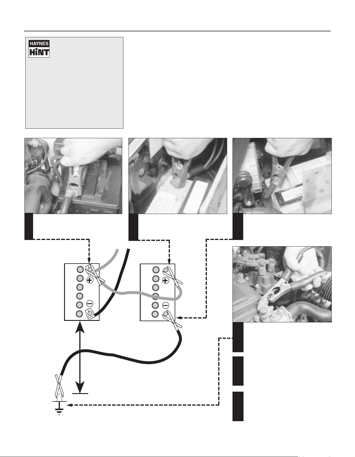
Connect one end of the red jump lead to
the positive (+) terminal of the flat
battery
Connect the other end of the red lead to
the positive (+) terminal of the booster
battery.
Connect one end of the black jump lead
to the negative (-) terminal of the
booster battery
Connect the other end of the black
jump lead to a bolt or bracket on the
engine block, well away from the
battery, on the vehicle to be started.
1
2
3
4
Make sure that the jump leads will not
come into contact with the fan, drivebelts or other moving parts of the
engine.
5
Start the engine using the booster
battery, then with the engine running at
idle speed, disconnect the jump leads in
the reverse order of connection.
6
Jump starting
Page 10
0•10
There are some very simple checks which
need only take a few minutes to carry out, but
which could save you a lot of inconvenience
and expense.
These "Weekly checks" require no great skill
or special tools, and the small amount of time
they take to perform could prove to be very
well spent, for example;
M Keeping an eye on tyre condition and
pressures, will not only help to stop them
wearing out prematurely, but could also save
your life.
M Many breakdowns are caused by electrical
problems. Battery-related faults are
particularly common, and a quick check on a
regular basis will often prevent the majority of
these.
M If your car develops a brake fluid leak, the
first time you might know about it is when your
brakes don't work properly . Checking the level
regularly will give advance warning of this kind
of problem.
M If the oil or coolant levels run low, the cost
of repairing any engine damage will be far
greater than fixing the leak, for example.
Underbonnet check points
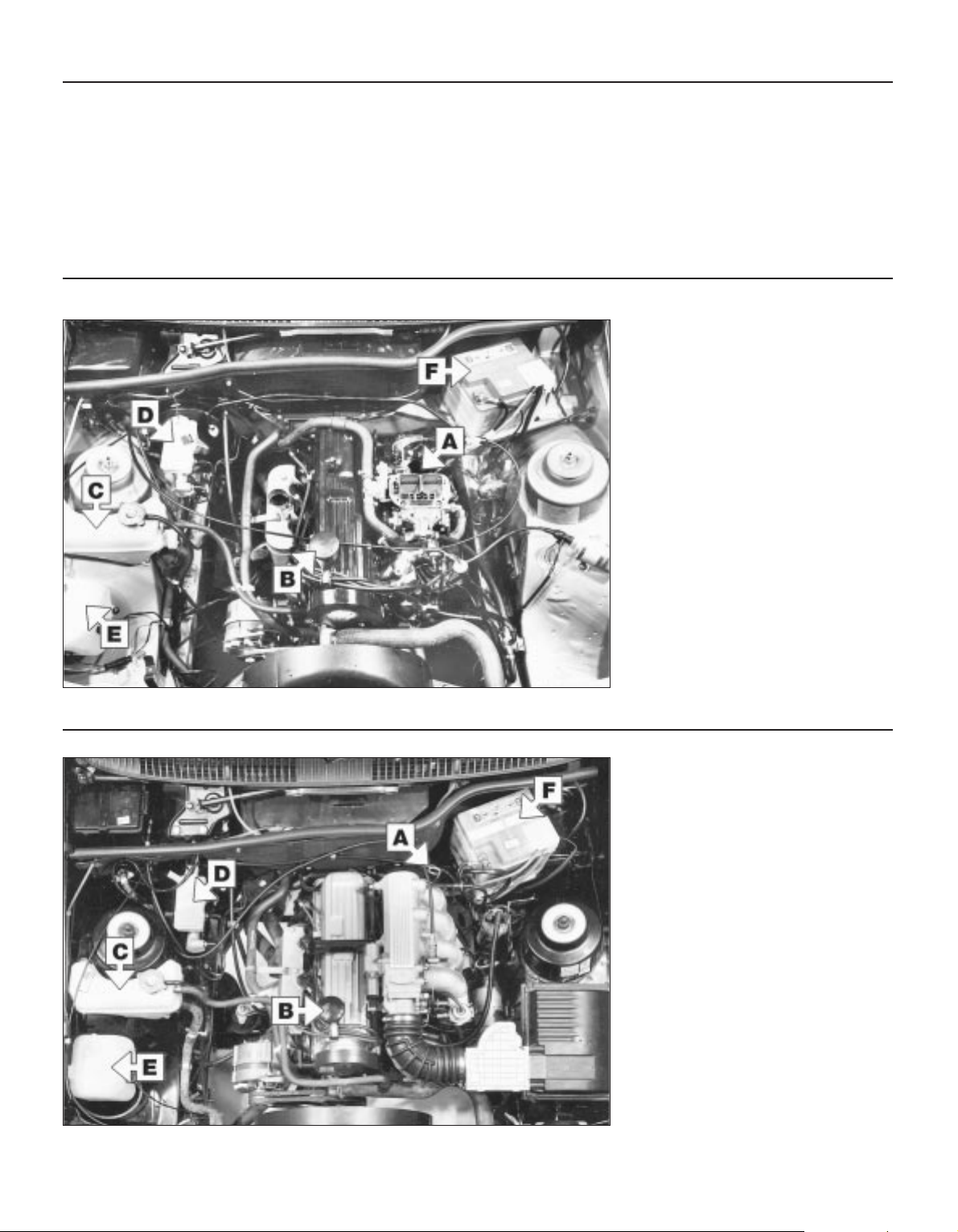
§
2.0 litre OHC
Carburettor model
(air cleaner removed for clarity)
A
Location of oil level dipstick
B
Engine oil filler cap
C
Coolant expansion tank
D
Brake fluid reservoir
E
Windscreen washer reservoir
F
Battery
§
2.0 litre OHC
Fuel injection model
A
Oil level dipstick
B
Engine oil filler cap
C
Coolant expansion tank
D
Brake fluid reservoir
E
Windscreen washer reservoir
F
Battery
Introduction
Weekly checks
Page 11
0•11
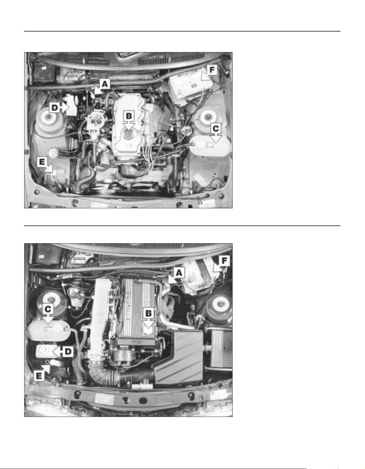
§
1.8 litre CVH
Air cleaner removed for clarity
A
Oil level dipstick
B
Engine oil filler cap
C
Coolant expansion tank
D
Brake fluid reservoir
E
Windscreen washer reservoir
F
Battery
§
2.0 litre DOHC
A
Oil level dipstick
B
Engine oil filler cap
C
Coolant expansion tank
D
Power steering fluid reservoir
E
Windscreen washer reservoir
F
Battery
Weekly checks
Page 12
Coolant level
Engine oil level
Before you start
4 Make sure that your car is on level ground.
4 Check the oil level before the car is driven,
or at least 5 minutes after the engine has been
switched off.
The correct oil
Modern engines place great demands on their
oil. It is very important that the correct oil for
your car is used (See “Lubricants and Fluids”).
Car Care
l If you have to add oil frequently, you should
check whether you have any oil leaks. Place
some clean paper under the car overnight,
and check for stains in the morning. If there
are no leaks, the engine may be burning oil
(see “Fault Finding”).
l Always maintain the level between the
upper and lower dipstick marks (see photo 3).
If the level is too low severe engine damage
may occur. Oil seal failure may result if the
engine is overfilled by adding too much oil.
0•12
Using a clean rag or paper towel remove
all oil from the dipstick. Insert the clean
dipstick into the tube as far as it will go, then
withdraw it again.
Add a mixture of water and antifreeze
through the expansion tank filler neck
until the coolant reaches the “MAX” level
mark. Refit the cap, turning it clockwise as far
as it will go until it is secure.
If topping-up is necessary, wait until the
engine is cold. Slowly turn the expansion
tank cap anti-clockwise to relieve the system
pressure. Once any pressure is released, turn
the cap anti-clockwise unti it can be lifted off.
The coolant level varies with the
temperature of the engine. When the
engine is cold, the coolant level should be at
the “MAX” mark. When the engine is hot, the
level may rise slightly above this mark.
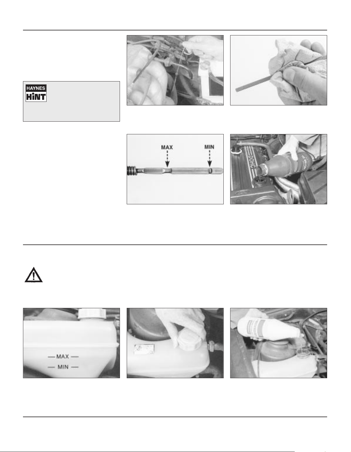
Note the oil level on the end of the
dipstick, which should be between the
upper (“MAX”) mark and lower (“MIN”) mark.
Approximately 1.0 litre of oil will raise the level
from the lower mark to the upper mark.
Oil is added through the filler cap.
Unscrew the cap and top-up the level; a
funnel may help to reduce spillage . Add the
oil slowly, checking the level on the dipstick
frequently. Avoid overfilling (see “Car Care”).
On some models, the dipstick is brightly
coloured for easy identification. Refer to
the photos on pages 0•10 and 0•11 for the
exact location for each engine type
1 2
3
1 2 3
4
Warning: DO NOT attempt to
remove the expansion tank
pressure cap when the engine
is hot, as there is a very great
risk of scalding. Do not leave
open containers of coolant
about, as it is poisonous.
Car Care
l With a sealed-type cooling system, adding
coolant should not be necessary on a regular
basis. If frequent topping-up is required, it is
likely there is a leak. Check the radiator, all
hoses and joint faces for signs of staining or
wetness, and rectify as necessary.
l It is important that antifreeze is used in the
cooling system all year round, not just during
the winter months. Don’t top-up with water
alone, as the antifreeze will become too
diluted.
If the oil is checked
immediately after driving the
vehicle, some of the oil will
remain in the upper engine
components, resulting in an inaccurate
reading on the dipstick!
Weekly checks
Page 13
Warning:Brake hydraulic fluid
can harm your eyes and
damage painted surfaces, so
use extreme caution when
handling and pouring it.
l Do not use fluid that has been
standing open for some time, as it
absorbs moisture from the air
which can cause a dangerous loss
of braking effectiveness.
Safety first
l If the reservoir requires repeated toppingup this is an indication of a fluid leak
somewhere in the system, which should be
investigated immediately.
l If a leak is suspected, the car should not be
driven until the braking system has been
checked. Never take any risks where brakes
are concerned.
l On ABS models, switch the ignition off and
pump the brake pedal at least 20 times or until
the pedal feels hard. Open the bonnet. Switch
on the ignition: the hydraulic unit pump will be
heard running. Wait until the pump stops, then
switch off the ignition.
Brake fluid level
0•13
Carefully add fluid avoiding spilling it on
surrounding paintwork. Use only the
specified hydraulic fluid; mixing different types
of fluid can cause damage to the system. After
filling to the correct level, refit the cap
securely, to prevent leaks and the entry of
foreign matter. Wipe off any spilt fluid.
When adding fluid, it’s a good idea to
inspect the reservoir. The system should
be drained and refilled if dirt is seen in the fluid
(see Chapter 9 for details).
The “MAX” and “MIN” marks are
indicated on the side of the reservoir. The
fluid level must be kept between the marks.
Disconnect the wiring plug (arrowed) before
removing the cap.
1
If topping-up is necessary, first wipe the
area around the filler cap with a clean rag
before removing the cap.
2
3 4
Screen washer fluid level
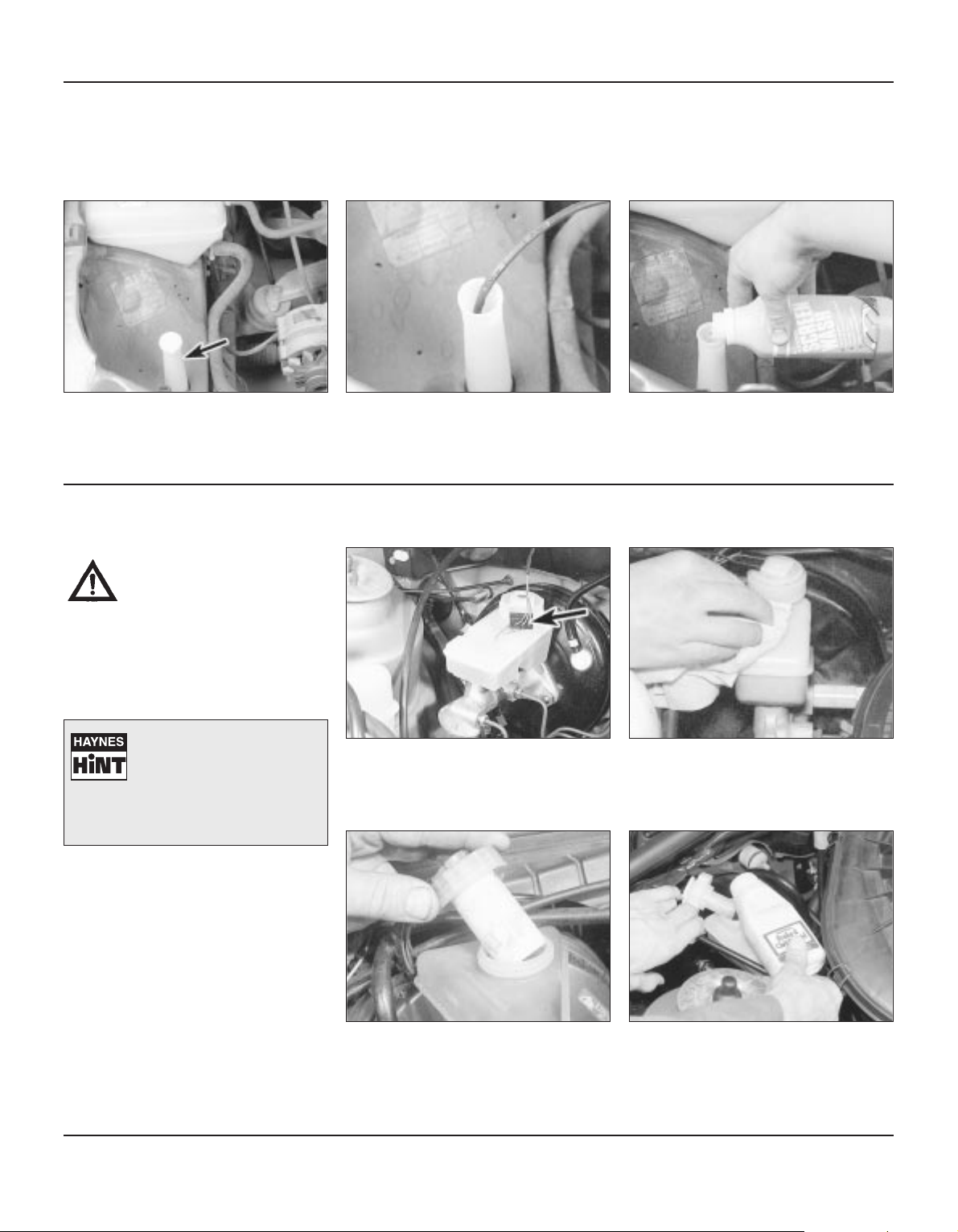
Some models have a visible reservoir,
whilst others have only the filler nozzle
(arrowed) showing. Either way, the location is
in the same place.
Top-up the washer reservoir using a
propietary screen wash.
On models with only the filler tube fitted,
a dipstick is fitted to show the quantity of
fluid left in the reservoir
Screenwash additives not only keep the
winscreen clean during foul weather, they also
prevent the washer system freezing in cold
weather - which is when you are likely to need
it most. Don’t top up using plain water as the
screenwash will become too diluted, and will
freeze during cold weather . On no account use
engine antifreeze in the washer system - this
could discolour or damage paintwork.
1 2 3
• Make sure that your car is
on level ground.
• The fluid level in the
master cylinder reservoir will
drop slightly as the brake pads wear
down, but the fluid level must never be
allowed to drop below the ‘MIN’ mark.
Weekly checks
Page 14
0•14
Before you start:
4 Park the vehicle on level ground.
4 Set the steering wheel pointing straight-
ahead.
4 The system should be at operating
temperature and the engine should be
turned off.
Safety First:
l The need for frequent topping-up indicates
a leak, which should be investigated
immediately.
Top-up if necessary with clean fluid of
the specified type If the level is checked
cold, use the “MIN” or “FULL COLD” mark.
Recheck the level at operating temperature.
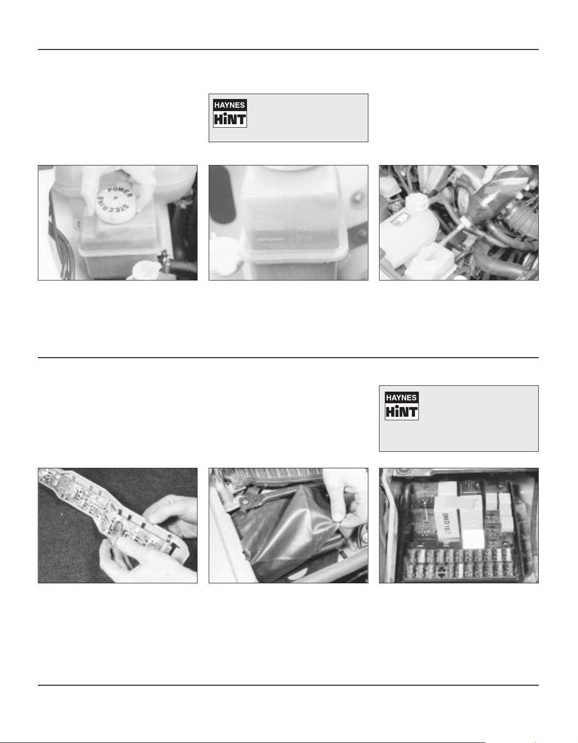
The fluid level should be up to the
“MAX” or upper “HOT” mark
The power steering fluid reservoir is
located next to the coolant expansion
tank. Clean around the filler cap and then
remove it should topping up be required.
1 2 3
For the check to be accurate
the steering must not be
turned once the engine has
been stopped.
Power steering fluid level
Weekly checks
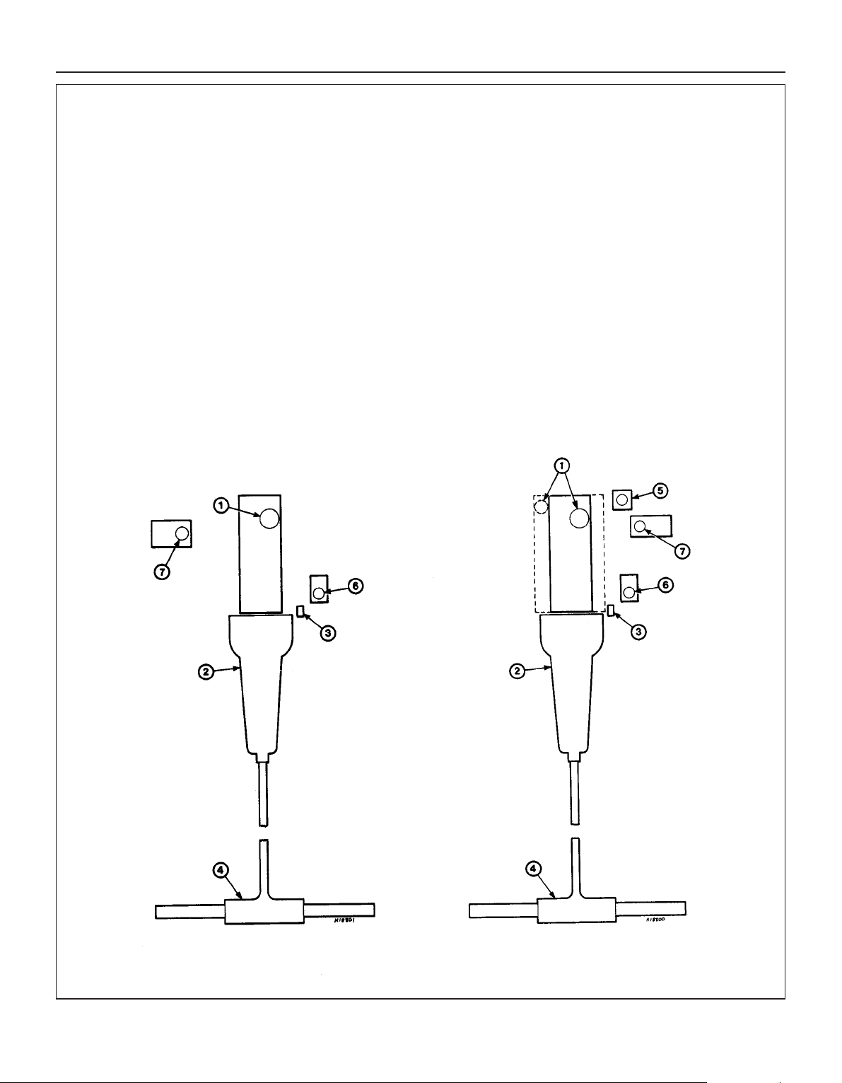
Electrical system
To replace a blown fuse, simply pull it out.
Fit a new fuse of the same rating,
available from car accessory shops.
It is important that you find the reason that the
fuse blew - a checking procedure is given in
Chapter 13.
If more than one indicator light or
headlight has failed it is likely that either a
fuse has blown or that there is a fault in the
circuit (refer to “Electrical fault-finding” in
Chapter 13).
The fuses are mounted in a box in the engine
compartment on the right-hand side of the
bulkhead. Remove the loose cover (and spring
clip if fitted), pulling the plastic clip, and
removing the plastic cover.
If a single indicator light, brake light or
headlight has failed it is likely that a bulb
has blown and will need to be replaced. Refer
to Chapter 12 for details.
If both brake lights have failed, it is possible
that the brake light switch above the brake
pedal needs adjusting. This simple operation
is described in Chapter 9.
1
If you need to check your
brake lights and indicators
unaided, back up to a wall
or garage door and operate
the lights. The reflected light should
show if they are working properly.
4 Check all external lights and the horn. Refer
to the appropriate Sections of Chapter 13 for
details if any of the circuits are found to be
inoperative.
4 Visually check all wiring connectors,
harnesses and retaining clips for security, and
for signs of chafing or damage.
2 3
Page 15
0•15
To remove a wiper blade, pull the arm
fully away from the glass until it locks.
Swivel the blade through 90°, press the
locking tab(s) with your fingers, and slide the
blade out of the arm's hooked end. On
refitting, ensure that the blade locks securely
into the arm.
Check the condition of the wiper blades;
if they are cracked or show any signs of
deterioration, or if the glass swept area is
smeared, renew them. For maximum clarity of
vision, wiper blades should be renewed
annually, as a matter of course.
21
Weekly checks
Battery
Caution: Before carrying out any work on the
vehicle battery, read the precautions given in
“Safety first” at the start of this manual.
4 Make sure that the battery tray is in good
condition, and that the clamp is tight.
Corrosion on the tray, retaining clamp and the
battery itself can be removed with a solution
of water and baking soda. Thoroughly rinse all
cleaned areas with water. Any metal parts
damaged by corrosion should be covered with
a zinc-based primer, then painted.
4 Periodically (approximately every three
months), check the charge condition of the
battery as described in Chapter 5A.
4 If the battery is flat, and you need to jump
start your vehicle, see “Roadside Repairs”.
The battery is located on the left-hand
side of the engine compartment. The
exterior of the battery should be inspected
periodically for damage such as a cracked
case or cover.
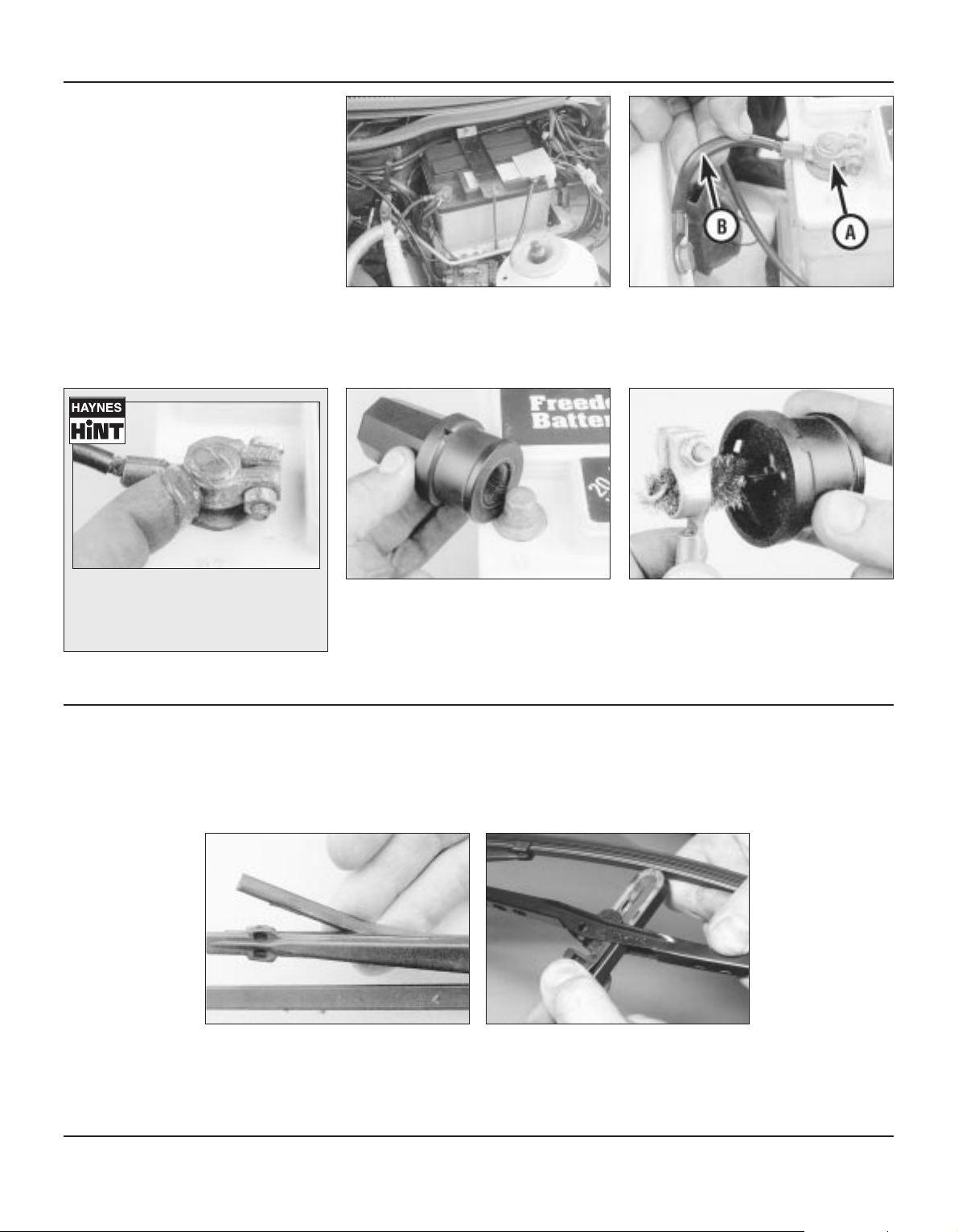
Check the tightness of battery clamps (A)
to ensure good electrical connections.
You should not be able to move them. Also
check each cable (B) for cracks and frayed
conductors.
If corrosion (white, fluffy deposits) is
evident, remove the cables from the
battery terminals, clean them with a small wire
brush, then refit them. Accessory stores sell a
useful tool for cleaning the battery post ...
1 2
3
... as well as the battery cable clamps
4
Battery corrosion can be kept to a
minimum by applying a layer of
petroleum jelly to the clamps and
terminals after they are reconnected.
Wiper blades
Page 16
0•16
Weekly checks
It is very important that tyres are in good
condition, and at the correct pressure - having
a tyre failure at any speed is highly dangerous.
Tyre wear is influenced by driving style - harsh
braking and acceleration, or fast cornering,
will all produce more rapid tyre wear. As a
general rule, the front tyres wear out faster
than the rears. Interchanging the tyres from
front to rear (“rotating” the tyres) may result in
more even wear. However, if this is completely
effective, you may have the expense of
replacing all four tyres at once!
Remove any nails or stones embedded in the
tread before they penetrate the tyre to cause
deflation. If removal of a nail does reveal that
the tyre has been punctured, refit the nail so
that its point of penetration is marked. Then
immediately change the wheel, and have the
tyre repaired by a tyre dealer.
Regularly check the tyres for damage in the
form of cuts or bulges, especially in the
sidewalls. Periodically remove the wheels, and
clean any dirt or mud from the inside and
outside surfaces. Examine the wheel rims for
signs of rusting, corrosion or other damage.
Light alloy wheels are easily damaged by
“kerbing” whilst parking; steel wheels may
also become dented or buckled. A new wheel
is very often the only way to overcome severe
damage.
New tyres should be balanced when they are
fitted, but it may become necessary to rebalance them as they wear, or if the balance
weights fitted to the wheel rim should fall off.
Unbalanced tyres will wear more quickly, as
will the steering and suspension components.
Wheel imbalance is normally signified by
vibration, particularly at a certain speed
(typically around 50 mph). If this vibration is
felt only through the steering, then it is likely
that just the front wheels need balancing. If,
however, the vibration is felt through the whole
car , the rear wheels could be out of balance.
Wheel balancing should be carried out by a
tyre dealer or garage.
Tyre Pressure Check
Check the tyre pressures regularly with
the tyres cold. Do not adjust the tyre
pressures immediately after the vehicle has
been used, or an inaccurate setting will result.
Tyre pressures are shown on the next page.
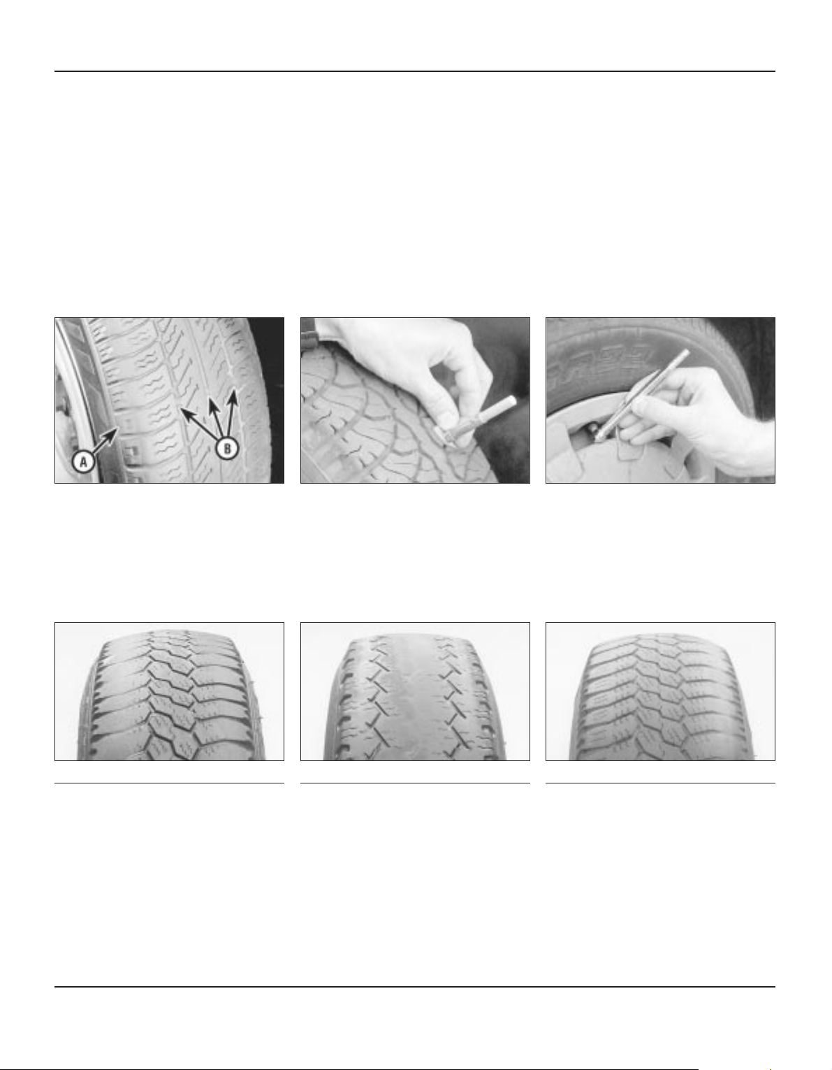
Tread Depth - manual check
Alternatively tread wear can be monitored
with a simple, inexpensive device known
as a tread depth indicator gauge.
Tread Depth - visual check
The original tyres have tread wear safety
bands (B), which will appear when the
tread depth reaches approximately 1.6 mm.
The band positions are indicated by a
triangular mark on the tyre sidewall (A).
1 2 3
Tyre condition and pressure
Tyre tread wear patterns
Shoulder Wear
Under-inflation (wear on both sides)
Under-inflation will cause overheating of the
tyre, because the tyre will flex too much, and
the tread will not sit correctly on the road
surface. This will cause a loss of grip and
excessive wear, not to mention the danger of
sudden tyre failure due to heat build-up.
Check and adjust pressures
Incorrect wheel camber (wear on one side)
Repair or renew suspension parts
Hard cornering
Reduce speed!
Centre Wear
Over-inflation
Over-inflation will cause rapid wear of the
centre part of the tyre tread, coupled with
reduced grip, harsher ride, and the danger of
shock damage occurring in the tyre casing.
Check and adjust pressures
If you sometimes have to inflate your car’s
tyres to the higher pressures specified for
maximum load or sustained high speed, don’t
forget to reduce the pressures to normal
afterwards.
Uneven Wear
Front tyres may wear unevenly as a result of
wheel misalignment. Most tyre dealers and
garages can check and adjust the wheel
alignment (or "tracking") for a modest charge.
Incorrect camber or castor
Repair or renew suspension parts
Malfunctioning suspension
Repair or renew suspension parts
Unbalanced wheel
Balance tyres
Incorrect toe setting
Adjust front wheel alignment
Note: The feathered edge of the tread which
typifies toe wear is best checked by feel.
4
Page 17
0•17
Weekly checks
Lubricants and fluids
Component or system Lubricant type/specification
1 Engine Multigrade engine oil, viscosity range SAE 10W/30 to 20W/50, to API SG/CD or better
2 Manual gearbox
4-speed (A, B and C type) Gear oil, viscosity SAE 80EP, to Ford spec SQM-2C 9008-A
5-speed (N type) Gear oil, viscosity SAE 80EP, to Ford spec ESD-M2C 175-A
5-speed (MT75 type) Gear oil to Ford spec ESD-M2C 186-A
3 Automatic transmission ATF to Ford spec SQM-2C 9010-A
4 Final drive Hypoid gear oil, viscosity SAE 90EP to Ford spec SQM-2C 9002-AA or 9003-AA
5 Power steering ATF to Ford spec SQM-2C 9010-A
6 Brake hydraulic system Brake fluid to Ford spec Amber SAM-1C 9103-A Fluid
7 Cooling system:
SOHC engines Soft water and antifreeze to Ford spec SSM-97 B-9103-A
CVH engines Soft water and antifreeze to Ford spec ESD-M97B49-A
DOHC engine Soft water and antifreeze to Ford spec SDM-M97B49-A
Note: From 1992, the cooling system on all models is filled with a long-life coolant mixture in production (“4-Year Longlife
Engine Coolant”/”Super Plus 40”). The manufacturers do not specify any renewal intervals for this later type of coolant as it is
intended to last the lifetime of the vehicle. Provided any topping-up is carried out with a similar coolant mixture of the correct
strength, coolant renewal is unnecessary. It is advisable to renew the coolant if the vehicle has covered a particularly high
mileage, or if the history of the car is uncertain, but this is up to the discretion of the individual owner.
CVH engines SOHC and DOHC engines
Page 18

0•18
Weekly checks
Note: Manufacturers often modify tyre sizes and pressure recommendations. The following is intended as a guide only. Refer to your vehicle
handbook or a Ford dealer for the latest recommendations
Tyre pressures (cold) - lbf/in2(bar): Front Rear
All Saloon, Hatchback and Estate models with normal load* 26 (1.8) 26 (1.8)
All Saloon and Hatchback models with full load . . . . . 29 (2.0) 36 (2.5)
Estate models with full load:
175 R 13H, 175 R 135,175 R 13T, 195/70 R 13H and
195/65 R 14T tyres . . . . . . . . . . . . . . . . . . . . . . . . . 29 (2.0) 48 (2.8)
195/60 R 14H and 195/60 VR 14 tyres . . . . . . . . . . 29 (2.0) 36 (2.5)
P100 models with light load . . . . . . . . . . . . . . . . . . . . 26 (1.8) 36 (2.5)
P100 models with full load . . . . . . . . . . . . . . . . . . . . . 50 (3.5) 65 (4.5)
*Normal load is defined as up to three passengers (or equivalent). For sustained high speeds add 1.5 lbf/in2(0.1 bar) for every 6 mph (10 km/h)
over 100 mph (160 km/h)
A light load is defined as one passenger plus up to 100 kg (220 lb) payload
Tyre pressures
Page 19
Engine
Oil filter type:
SOHC and DOHC . . . . . . . . . . . . . . . . . . . . . . . . . . . . . . . . . . . . . . . . Champion C102
CVH . . . . . . . . . . . . . . . . . . . . . . . . . . . . . . . . . . . . . . . . . . . . . . . . . . . Champion C104
Valve clearances (cold):
SOHC:
Inlet . . . . . . . . . . . . . . . . . . . . . . . . . . . . . . . . . . . . . . . . . . . . . . . . . 0.20 ± 0.03 mm (0.008 ± 0.001 in)
Exhaust . . . . . . . . . . . . . . . . . . . . . . . . . . . . . . . . . . . . . . . . . . . . . . 0.25 ± 0.03 mm (0.010 ± 0.001 in)
DOHC and CVH:
Inlet . . . . . . . . . . . . . . . . . . . . . . . . . . . . . . . . . . . . . . . . . . . . . . . . . Not applicable (hydraulic cam followers)
Exhaust . . . . . . . . . . . . . . . . . . . . . . . . . . . . . . . . . . . . . . . . . . . . . . Not applicable (hydraulic cam followers)
Chapter 1
Routine maintenance and servicing
Air cleaner filter element renewal . . . . . . . . . . . . . . . . . . . . . . . . . . . .38
Air cleaner inlet air temperature control check . . . . . . . . . . . . . . . . . .36
Air conditioner refrigerant charge check . . . . . . . . . . . . . . . . . . . . . .26
Automatic transmission brake band adjustment . . . . . . . . . . . . . . . .40
Automatic transmission fluid level check . . . . . . . . . . . . . . . . . . . . . .17
Automatic transmission selector lubrication . . . . . . . . . . . . . . . . . . .28
Auxiliary drivebelt check . . . . . . . . . . . . . . . . . . . . . . . . . . . . . . . . . . .21
Battery electrolyte level check . . . . . . . . . . . . . . . . . . . . . . . . . . . . . . .6
Battery terminal check . . . . . . . . . . . . . . . . . . . . . . . . . . . . . . . . . . . .22
Brake fluid renewal . . . . . . . . . . . . . . . . . . . . . . . . . . . . . . . . . . . . . . .44
Brake system seal and hose renewal . . . . . . . . . . . . . . . . . . . . . . . . .43
Brake pipe and hose check . . . . . . . . . . . . . . . . . . . . . . . . . . . . . . . .32
Camshaft drivebelt renewal . . . . . . . . . . . . . . . . . . . . . . . . . . . . . . . .45
Crankcase ventilation system check . . . . . . . . . . . . . . . . . . . . . . . . .35
Crankcase ventilation vent valve renewal . . . . . . . . . . . . . . . . . . . . . .42
Driveshaft check . . . . . . . . . . . . . . . . . . . . . . . . . . . . . . . . . . . . . . . . .30
Electrical system check . . . . . . . . . . . . . . . . . . . . . . . . . . . . . . . . . . . .5
Engine coolant renewal . . . . . . . . . . . . . . . . . . . . . . . . . . . . . . . . . . .46
Engine idle speed check . . . . . . . . . . . . . . . . . . . . . . . . . . . . . . . . . . .15
Engine oil and filter renewal . . . . . . . . . . . . . . . . . . . . . . . . . . . . . . . . .8
Engine valve clearance check . . . . . . . . . . . . . . . . . . . . . . . . . . . . . .23
Exhaust system check . . . . . . . . . . . . . . . . . . . . . . . . . . . . . . . . . . . .12
Final drive oil level check . . . . . . . . . . . . . . . . . . . . . . . . . . . . . . . . . .27
Fluid leak check . . . . . . . . . . . . . . . . . . . . . . . . . . . . . . . . . . . . . . . . .10
Fluid level checks . . . . . . . . . . . . . . . . . . . . . . . . . . . . . . . . . . . . . . . . .3
Ford Sierra maintenance schedule . . . . . . . . . . . . . . . . . . . . . . . . . . . .1
Front and rear brake pad/shoe check . . . . . . . . . . . . . . . . . . . . . . . . .9
Fuel filter renewal . . . . . . . . . . . . . . . . . . . . . . . . . . . . . . . . . . . . . . . .41
Handbrake check . . . . . . . . . . . . . . . . . . . . . . . . . . . . . . . . . . . . . . . .24
Hinge and lock check and lubrication . . . . . . . . . . . . . . . . . . . . . . . .19
Idle speed linkage clean . . . . . . . . . . . . . . . . . . . . . . . . . . . . . . . . . . .33
Ignition system component check . . . . . . . . . . . . . . . . . . . . . . . . . . .39
Introduction . . . . . . . . . . . . . . . . . . . . . . . . . . . . . . . . . . . . . . . . . . . . .2
Manual gearbox oil level check . . . . . . . . . . . . . . . . . . . . . . . . . . . . .18
Mixture adjustment check . . . . . . . . . . . . . . . . . . . . . . . . . . . . . . . . .16
Oil filler cap check . . . . . . . . . . . . . . . . . . . . . . . . . . . . . . . . . . . . . . .14
Pulse air filter element renewal . . . . . . . . . . . . . . . . . . . . . . . . . . . . . .37
Radiator matrix and air conditioner condenser clean . . . . . . . . . . . . .25
Road test . . . . . . . . . . . . . . . . . . . . . . . . . . . . . . . . . . . . . . . . . . . . . .34
Roadwheel security check . . . . . . . . . . . . . . . . . . . . . . . . . . . . . . . . .13
Seat belt check . . . . . . . . . . . . . . . . . . . . . . . . . . . . . . . . . . . . . . . . . .11
Spark plug renewal . . . . . . . . . . . . . . . . . . . . . . . . . . . . . . . . . . . . . . .20
Steering and suspension security check . . . . . . . . . . . . . . . . . . . . . .29
Tyre checks . . . . . . . . . . . . . . . . . . . . . . . . . . . . . . . . . . . . . . . . . . . . .4
Underbody inspection . . . . . . . . . . . . . . . . . . . . . . . . . . . . . . . . . . . .31
Wiper blade check . . . . . . . . . . . . . . . . . . . . . . . . . . . . . . . . . . . . . . . .7
1•1
Easy, suitable for
novice with little
experience
Fairly easy, suitable
for beginner with
some experience
Fairly difficult,
suitable for competent
DIY mechanic
Difficult, suitable for
experienced DIY
mechanic
Very difficult,
suitable for expert
DIY or professional
Degrees of difficulty
Specifications
Contents
1
Page 20

Cooling system
Drivebelt tensions:
Air conditioning system compressor . . . . . . . . . . . . . . . . . . . . . . . . . 10.0 mm (0.4 in) deflection at the midpoint of the belt’s longest run
under firm thumb pressure
Coolant pump/alternator . . . . . . . . . . . . . . . . . . . . . . . . . . . . . . . . . . 10.0 mm (0.4 in) deflection midway between coolant pump and
alternator (or power steering pump) pulleys under firm thumb pressure
Fuel system
Air filter element:
Carburettor type:
1.3 and 1.6 litre (SOHC - Ford carburettor) . . . . . . . . . . . . . . . . . . Champion W110
1.6 litre (SOHC - Weber carburettor) and 1.8 litre SOHC . . . . . . . . Champion W118
1.6 litre (SOHC - 1984-on) and 2.0 litre SOHC . . . . . . . . . . . . . . . . Champion W152
1.8 litre CVH . . . . . . . . . . . . . . . . . . . . . . . . . . . . . . . . . . . . . . . . . . Champion W219
2.0 litre DOHC . . . . . . . . . . . . . . . . . . . . . . . . . . . . . . . . . . . . . . . . . Champion W152
Fuel injection type:
2.0 litre SOHC and DOHC . . . . . . . . . . . . . . . . . . . . . . . . . . . . . . . . Champion U507
1.6 and 1.8 litre (R6A type) CVH . . . . . . . . . . . . . . . . . . . . . . . . . . . Champion W219
Fuel filter:
All fuel injection models . . . . . . . . . . . . . . . . . . . . . . . . . . . . . . . . . . . Champion L204
Ignition system
Spark plugs:
Make and type:
All except 1.8 CVH, CVH (R6A), 2.0 DOHC and P100 . . . . . . . . . . . . Champion RF7YCC or RF7YC
1.8 litre CVH . . . . . . . . . . . . . . . . . . . . . . . . . . . . . . . . . . . . . . . . . . . . Champion RC7YCC or RC7YC
P100 . . . . . . . . . . . . . . . . . . . . . . . . . . . . . . . . . . . . . . . . . . . . . . . . . . Champion RF7YC or F7YC
1.6 and 1.8 litre (R6A type) CVH . . . . . . . . . . . . . . . . . . . . . . . . . . . . . Champion RC7YCC
2.0 litre DOHC . . . . . . . . . . . . . . . . . . . . . . . . . . . . . . . . . . . . . . . . . . . Champion RC7YCC
Electrode gap*:
Champion F7YCC or RC7YCC . . . . . . . . . . . . . . . . . . . . . . . . . . . . . . 0.8 mm (0.032 in)
Champion RF7YC, F7YC or RC7YC . . . . . . . . . . . . . . . . . . . . . . . . . . 0.7 mm (0.028 in)
Ignition HT leads
Resistance . . . . . . . . . . . . . . . . . . . . . . . . . . . . . . . . . . . . . . . . . . . . . . . 30 k ohms maximum per lead
Type:
All SOHC models . . . . . . . . . . . . . . . . . . . . . . . . . . . . . . . . . . . . . . . . Champion LS-09 or LS-10 boxed set
1.8 litre CVH . . . . . . . . . . . . . . . . . . . . . . . . . . . . . . . . . . . . . . . . . . . . Champion LS-10 boxed set
1.6 and 1.8 litre (R6A type) CVH . . . . . . . . . . . . . . . . . . . . . . . . . . . . Champion LS-30 boxed set
2.0 litre DOHC . . . . . . . . . . . . . . . . . . . . . . . . . . . . . . . . . . . . . . . . . . . Champion LS-29 boxed set
*The spark plug gap quoted is that recommended by Champion for their specified plugs listed above. If spark plugs of any other type are to be
fitted, refer to their manufacturer’s recommendations.
Brakes
Brake pad friction material minimum thickness . . . . . . . . . . . . . . . . . . . 1.5 mm (0.06 in)
Brake shoe friction material minimum thickness . . . . . . . . . . . . . . . . . . 1.0 mm (0.04 in)
Torque wrench settings Nm lbf ft
Engine oil drain plug:
SOHC and DOHC . . . . . . . . . . . . . . . . . . . . . . . . . . . . . . . . . . . . . . . . 21 to 28 16 to 21
CVH . . . . . . . . . . . . . . . . . . . . . . . . . . . . . . . . . . . . . . . . . . . . . . . . . . . 20 to 30 15 to 22
Engine block coolant drain plug (where fitted) . . . . . . . . . . . . . . . . . . . . 21 to 25 16 to 18
Manual gearbox:
Oil filler/level plug:
A,B,C and N types . . . . . . . . . . . . . . . . . . . . . . . . . . . . . . . . . . . . . 33 to 41 24 to 30
MT75 type . . . . . . . . . . . . . . . . . . . . . . . . . . . . . . . . . . . . . . . . . . . . 29 to 41 21 to 30
Oil drain plug:
MT75 type . . . . . . . . . . . . . . . . . . . . . . . . . . . . . . . . . . . . . . . . . . . . 29 to 41 21 to 30
Final drive oil filler plug . . . . . . . . . . . . . . . . . . . . . . . . . . . . . . . . . . . . . . 35 to 45 26 to 33
Roadwheel nuts:
Saloon, Hatchback and Estate models (steel and alloy wheels) . . . . 70 to 100 52 to 74
P100 models . . . . . . . . . . . . . . . . . . . . . . . . . . . . . . . . . . . . . . . . . . . . 85 to 90 63 to 66
Spark plugs:
SOHC models . . . . . . . . . . . . . . . . . . . . . . . . . . . . . . . . . . . . . . . . . . . 20 to 28 15 to 21
CVH models . . . . . . . . . . . . . . . . . . . . . . . . . . . . . . . . . . . . . . . . . . . . 18 to 33 13 to 24
DOHC models . . . . . . . . . . . . . . . . . . . . . . . . . . . . . . . . . . . . . . . . . . . 15 to 21 11 to 15
Brake caliper guide bolts:
Front . . . . . . . . . . . . . . . . . . . . . . . . . . . . . . . . . . . . . . . . . . . . . . . . . . 20 to 25 15 to 18
Rear . . . . . . . . . . . . . . . . . . . . . . . . . . . . . . . . . . . . . . . . . . . . . . . . . . . 31 to 35 23 to 26
1•2 Servicing specifications
Page 21

The maintenance intervals in this manual
are provided with the assumption that you will
be carrying out the work yourself. These are
the minimum maintenance intervals
recommended by the manufacturer for
vehicles driven daily. If you wish to keep your
vehicle in peak condition at all times, you may
wish to perform some of these procedures
more often. We encourage frequent
maintenance, because it enhances the
efficiency, performance and resale value of
your vehicle.
If the vehicle is driven in dusty areas, used
to tow a trailer, or driven frequently at slow
speeds (idling in traffic) or on short journeys,
more frequent maintenance intervals are
recommended.
When the vehicle is new, it should be
serviced by a factory-authorised dealer
service department, in order to preserve the
factory warranty.
Capacities
Engine oil
SOHC engines:
With filter . . . . . . . . . . . . . . . . . . . . . . . . . . . . . . . . . . . . . . . . . . . . . . . 3.75 litres (6.6 pints)
Without filter . . . . . . . . . . . . . . . . . . . . . . . . . . . . . . . . . . . . . . . . . . . . 3.25 litres (5.7 pints)
DOHC engine:
With filter . . . . . . . . . . . . . . . . . . . . . . . . . . . . . . . . . . . . . . . . . . . . . . . 4.5 litres (7.9 pints)
Without filter . . . . . . . . . . . . . . . . . . . . . . . . . . . . . . . . . . . . . . . . . . . . 4.0 litres (7.0 pints)
1.6 litre CVH engine:
With filter . . . . . . . . . . . . . . . . . . . . . . . . . . . . . . . . . . . . . . . . . . . . . . . 3.5 litres (6.2 pints)
Without filter . . . . . . . . . . . . . . . . . . . . . . . . . . . . . . . . . . . . . . . . . . . . 3.25 litres (5.7 pints)
1.8 CVH engines:
With filter . . . . . . . . . . . . . . . . . . . . . . . . . . . . . . . . . . . . . . . . . . . . . . . 4.0 litres (7.0 pints)
Without filter . . . . . . . . . . . . . . . . . . . . . . . . . . . . . . . . . . . . . . . . . . . . 3.5 litres (6.2 pints)
Cooling system (including heater)
SOHC engines . . . . . . . . . . . . . . . . . . . . . . . . . . . . . . . . . . . . . . . . . . . . 8.0 litres (14.1 pints)
DOHC engine:
Carburettor models . . . . . . . . . . . . . . . . . . . . . . . . . . . . . . . . . . . . . . . 7.0 litres (12.3 pints)
Fuel injection models . . . . . . . . . . . . . . . . . . . . . . . . . . . . . . . . . . . . . 7.3 litres (12.8 pints)
CVH engines:
1.6 and 1.8 litre (R2A) . . . . . . . . . . . . . . . . . . . . . . . . . . . . . . . . . . . . . 9.5 litres (16.7 pints)
1.8 litre (R6A) . . . . . . . . . . . . . . . . . . . . . . . . . . . . . . . . . . . . . . . . . . . 7.9 litres (13.9 pints)
Fuel tank
All models except P100 . . . . . . . . . . . . . . . . . . . . . . . . . . . . . . . . . . . . . 60.0 litres (13.2 gals)
P100 models . . . . . . . . . . . . . . . . . . . . . . . . . . . . . . . . . . . . . . . . . . . . . . 66.0 litres (14.5 gals)
Manual gearbox
A1 and A2 types . . . . . . . . . . . . . . . . . . . . . . . . . . . . . . . . . . . . . . . . . . . 0.98 litre (1.72 pints)
B type . . . . . . . . . . . . . . . . . . . . . . . . . . . . . . . . . . . . . . . . . . . . . . . . . . . 1.46 litres (2.57 pints)
C type . . . . . . . . . . . . . . . . . . . . . . . . . . . . . . . . . . . . . . . . . . . . . . . . . . . 1.25 litres (2.20 pints)
N type up to 1987 . . . . . . . . . . . . . . . . . . . . . . . . . . . . . . . . . . . . . . . . . . 1.90 litres (3.34 pints)
N type from 1987 . . . . . . . . . . . . . . . . . . . . . . . . . . . . . . . . . . . . . . . . . . 1.25 litres (2.20 pints)
MT75 type . . . . . . . . . . . . . . . . . . . . . . . . . . . . . . . . . . . . . . . . . . . . . . . . 1.2 litres (2.1 pints)
Automatic transmission
C3 type . . . . . . . . . . . . . . . . . . . . . . . . . . . . . . . . . . . . . . . . . . . . . . . . . . 6.3 litres (11.1 pints)
A4LD type . . . . . . . . . . . . . . . . . . . . . . . . . . . . . . . . . . . . . . . . . . . . . . . . 8.5 litres (15.0 pints)
Final drive (from dry)
All models except 1.3 and 1.6 litre Hatchback and P100 . . . . . . . . . . . 0.9 litre (1.6 pints)
1.3 and 1.6 litre Hatchback models . . . . . . . . . . . . . . . . . . . . . . . . . . . . 0.8 litre (1.4 pints)
P100 models (rear axle) . . . . . . . . . . . . . . . . . . . . . . . . . . . . . . . . . . . . . 1.14 litres (2.0 pints)
Power steering
All models . . . . . . . . . . . . . . . . . . . . . . . . . . . . . . . . . . . . . . . . . . . . . . . . 0.65 litre (1.14 pints)
Servicing specifications 1•3
1
1 Ford Sierra maintenance schedule
Page 22

1•4 Maintenance schedule
Every 250 miles (400 km) or weekly
mm Check the engine oil level (Section 3)
mm Check the engine coolant level (Section 3)
mm Check the brake fluid level (Section 3)
mm Check the power steering fluid level (Section 3)
mm Check the screen washer fluid level (Section 3)
mm Visually examine the tyres for tread depth, and wear
or damage (Section 4)
mm Check and if necessary adjust the tyre pressures
(Section 4)
mm Check and if necessary top-up the battery electrolyte
level - where applicable (Section 6)
mm Check the operation of the horn, all lights, and the
wipers and washers (Sections 5 and 7)
Every 6000 miles (10 000 km) or
6 months - whichever comes sooner
mm Renew engine oil and filter (Section 8)
mm Check brake pads or shoes for wear (front and rear)
(Section 9)
mm Check operation of brake fluid level warning indicator
(Section 9)
mm Inspect engine bay and underside of vehicle for fluid
leaks or other signs of damage (Section 10)
mm Check function and condition of seat belts
(Section 11)
mm Check condition and security of exhaust system
(Section 12)
mm Check tightness of wheel nuts (Section 13)
mm Clean oil filler cap (Section 14)
mm Check idle speed (where applicable) (Section 15)
mm Check mixture adjustment (where applicable)
(Section 16)
Every 12 000 miles (20 000 km) or
12 months - whichever comes sooner
mm Check automatic transmission fluid level (engine hot)
(Section 17)
mm Check manual gearbox oil level (Section 18)
mm Check operation of latches, check straps and locks;
lubricate if necessary (Section 19)
mm Renew spark plugs (Section 20)
mm Check condition and tension of auxiliary drivebelt(s);
adjust or renew as necessary (Section 21)
mm Check tightness of battery terminals, clean and
neutralise corrosion if necessary (Section 22)
mm Check engine valve clearances - SOHC only
(Section 23)
mm Check handbrake mechanism (Section 24)
Every 24 000 miles (40 000 km) or
2 years - whichever comes sooner
mm Check air cleaner inlet air temperature control
operation (carburettor models) (Section 36)
mm Renew pulse air filter element (1.6 litre CVH)
(Section 37)
mm Renew air cleaner element (Section 38)
mm Clean and inspect distributor cap and HT leads
(Section 39)
mm Check automatic transmission brake band
adjustment (Section 40)
mm Renew fuel filter (fuel-injection models only)
(Section 41)
mm Renew crankcase ventilation vent valve (SOHC and
DOHC) (Section 42)
mm Clean radiator matrix and air conditioning condenser
fins (where applicable) (Section 25)
mm Check air conditioning refrigerant charge (where
applicable) (Section 26)
mm Check final drive oil level (Section 27)
mm Lubricate automatic transmission selector/kickdown
linkage (Section 28)
mm Check security and condition of steering and
suspension components, gaiters and boots
(Section 29)
mm Check condition and security of driveshaft joints and
gaiters (Section 30)
mm Inspect underbody and panels for corrosion or other
damage (Section 31)
mm Inspect brake pipes and hoses (Section 32)
mm Clean idle speed control linkage at throttle (where
applicable) (Section 33)
mm Road test and check operation of ABS (Section 34)
mm Check crankcase ventilation system (Section 35)
Every 36 000 miles (60 000 km) or
3 years - whichever comes sooner
mm Renew brake hydraulic system seals and hoses if
necessary (Section 43)
mm Renew brake hydraulic fluid (Section 44)
mm Renew camshaft drivebelt (optional on SOHC
models - compulsory on CVH) (Section 45)
mm Renew coolant (Section 46)
Every 12 000 miles (20 000 km) or
12 months - whichever comes sooner
(continued)
Page 23
Maintenance - component location 1•5
1
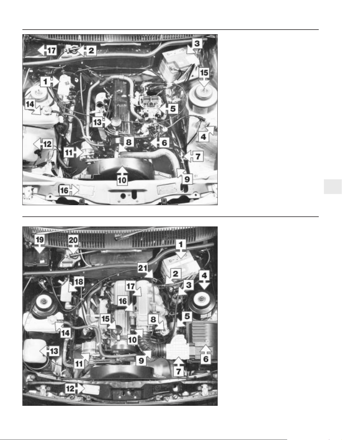
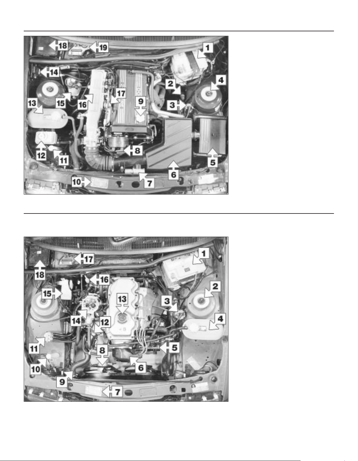
Underbonnet view of a 1985 2.0 litre SOHC
fuel injection model
1 Battery
2 Brake servo non-return valve
3 Ignition coil
4 Suspension strut top
5 Fuel filter
6 Air cleaner
7 Airflow meter
8 Fuel pressure regulator
9 Air inlet hose
10 Throttle body
11 Alternator
12 VIN plate
13 Windscreen washer reservoir
14 Coolant expansion tank
15 Oil filler cap
16 Idle speed control valve
17 Inlet manifold
18 Brake fluid reservoir
19 Fusebox
20 Windscreen wiper motor
21 Engine oil level dipstick
Underbonnet view of a 1983 2.0 litre SOHC
carburettor model (air cleaner removed)
1 Brake fluid reservoir
2 Windscreen wiper motor
3 Battery
4 Ignition coil
5 Carburettor
6 Distributor
7 Fuel pressure regulator
8 Thermostat housing
9 Radiator top hose
10 Upper fan shroud
11 Alternator
12 Windscreen washer reservoir
13 Oil filler cap
14 Cooler expansion tank
15 Suspension strut top
16 VIN plate
17 Fusebox
Page 24
1•6 Maintenance - component location
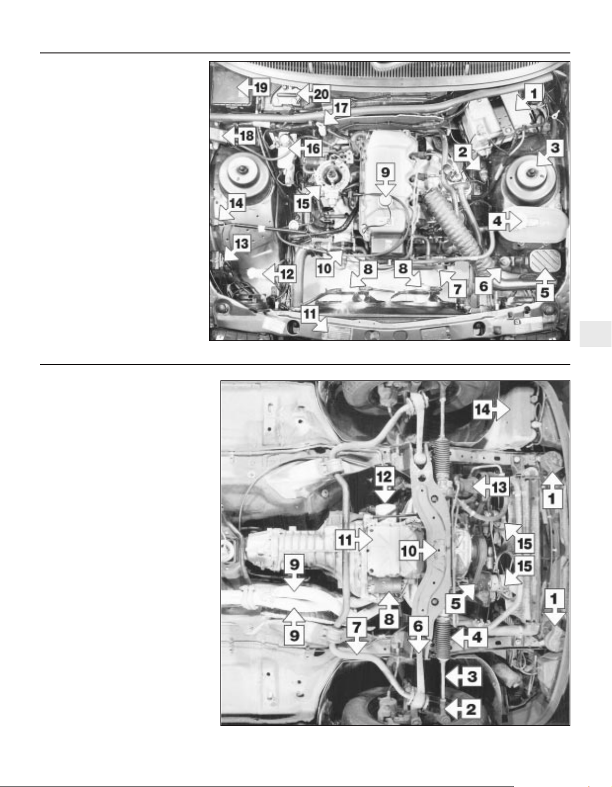
Underbonnet view of a 1990 2.0 litre DOHC
fuel injection model
1 Battery
2 Braking system deceleration-sensitive valve
3 Ignition coil
4 Suspension strut top
5 Air cleaner
6 Plenum chamber
7 Idle speed control valve
8 Distributor
9 Oil filler cap
10 VIN plate
11 Windscreen washer reservoir filler neck
12 Power steering fluid reservoir
13 Coolant expansion tank
14 Manifold absolute pressure (MAP) sensor
15 Brake fluid reservoir
16 Inlet manifold
17 Fuel pressure regulator
18 Fusebox
19 Windscreen wiper motor
Underbonnet view of a 1989 1.8 litre (R2A)
CVH model (air cleaner removed)
1 Battery
2 Suspension strut top
3 Ignition coil
4 Coolant expansion tank
5 Alternator
6 Distributor cap shroud
7 VIN plate
8 Electric cooling fan
9 Radiator top hose
10 Windscreen washer reservoir
11 Fuel vapour separator
12 Thermostat housing
13 Oil filler cap
14 Carburettor
15 Brake fluid reservoir
16 Engine oil level dipstick
17 Windscreen wiper motor
18 Fusebox
Page 25
Maintenance - component location 1•7
1
Front underside view of a 1990
2.0 GLS model
1 Horns
2 Tie-rod end
3 Tie-rod
4 Gaiter
5 Coolant pump
6 Suspension lower arm
7 Anti-roll bar
8 Starter motor
9 Exhaust downpipes
10 Crossmember
11 Engine sump
12 Oil filter
13 Power steering fluid pump
14 Windscreen washer reservoir
15 Cooling fans
Underbonnet view of a 1992 1.6 litre
CVH model (air cleaner removed)
1 Battery
2 Braking system deceleration-sensitive
valve
3 Suspension strut top
4 Coolant expansion tank
5 Pulse-air filter
6 Vacuum-operated air valve
7 Alternator
8 Cooling fans
9 Oil filler cap
10 Thermostat housing
11 VIN plate
12 Windscreen washer reservoir filler neck
13 Ignition module
14 Pulse-air control solenoid
15 CFI unit
16 Brake fluid reservoir
17 Engine oil level dipstick
18 Manifold absolute pressure (MAP)
Sensor
19 Fusebox
20 Windscreen wiper motor
Page 26
1•8 Maintenance - component location
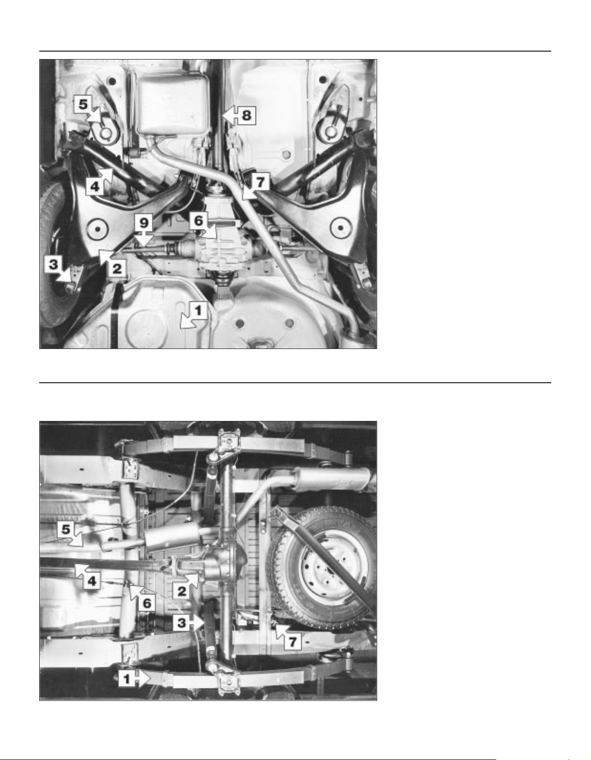
Rear underside view of a Hatchback
models
1 Fuel tank
2 Suspension lower arm
3 Lower shock absorber mounting
4 Suspension crossmember
5 Suspension guide plate
6 Final drive unit
7 Exhaust system
8 Propeller shaft
9 Driveshaft
Rear underside view of a P100 model
1 Suspension leaf spring
2 Rear axle
3 Shock absorber
4 Propeller shaft
5 Exhaust system
6 Handbrake cable adjuster
7 Brake load apportioning valve
Page 27
General information
This Chapter is designed to help the home
mechanic maintain his/her vehicle for safety,
economy, long life and peak performance.
The Chapter contains a master
maintenance schedule, followed by Sections
dealing specifically with each task in the
schedule. Visual checks, adjustments,
component renewal and other helpful items
are included. Refer to the accompanying
illustrations of the engine compartment and
the underside of the vehicle for the locations
of the various components.
Servicing your vehicle in accordance with
the mileage/time maintenance schedule and
the following Sections will provide a planned
maintenance programme, which should result
in a long and reliable service life. This is a
comprehensive plan, so maintaining some
items but not others at the specified service
intervals, will not produce the same results.
As you service your vehicle, you will discover
that many of the procedures can - and should be grouped together, because of the particular
procedure being performed, or because of the
close proximity of two otherwise-unrelated
components to one another. For example, if
the vehicle is raised for any reason, the exhaust
can be inspected at the same time as the
suspension and steering components.
The first step in this maintenance
programme is to prepare yourself before the
actual work begins. Read through all the
Sections relevant to the work to be carried
out, then make a list and gather together all
the parts and tools required. If a problem is
encountered, seek advice from a parts
specialist, or a dealer service department.
Intensive maintenance
If, from the time the vehicle is new, the
routine maintenance schedule is followed
closely, and frequent checks are made of fluid
levels and high-wear items, as suggested
throughout this manual, the engine will be
kept in relatively good running condition, and
the need for additional work will be minimised.
It is possible that there will be times when
the engine is running poorly due to the lack of
regular maintenance. This is even more likely
if a used vehicle, which has not received
regular and frequent maintenance checks, is
purchased. In such cases, additional work
may need to be carried out, outside of the
regular maintenance intervals.
If engine wear is suspected, a compression
test will provide valuable information
regarding the overall performance of the main
internal components. Such a test can be used
as a basis to decide on the extent of the work
to be carried out. If, for example, a
compression test indicates serious internal
engine wear, conventional maintenance as
described in this Chapter will not greatly
improve the performance of the engine, and
may prove a waste of time and money, unless
extensive overhaul work is carried out first.
The following series of operations are those
most often required to improve the
performance of a generally poor-running
engine:
Primary operations
a) Clean, inspect and test the battery
b) Check all the engine-related fluids
c) Check the condition and tension of the
auxiliary drivebelt
d) Renew the spark plugs
e) Inspect the distributor cap and HT leads -
as applicable
f) Check the condition of the air cleaner
filter element, and renew if necessary
g) Renew the fuel filter
h) Check the condition of all hoses, and
check for fluid leaks
i) Check the idle speed and mixture settings
- as applicable
If the above operations do not prove fully
effective, carry out the following secondary
operations:
Secondary operations
a) Check the charging system
b) Check the ignition system
c) Check the fuel system
d) Renew the distributor cap and rotor arm -
as applicable
f) Renew the ignition HT leads - as
applicable
2 Introduction
See “Weekly checks”.
See “Weekly checks”.
See “Weekly checks”.
See “Weekly checks”.
See “Weekly checks”.
7 Wiper blade check
6 Battery electrolyte level check
5 Electrical system check
4 Tyre checks
3 Fluid level checks
1 Frequent oil and filter changes are the most
important preventative maintenance
procedures which can be undertaken by the
DIY owner. As engine oil ages, it becomes
diluted and contaminated, which leads to
premature engine wear.
2 Before starting this procedure, gather
together all the necessary tools and materials.
Also make sure that you have plenty of clean
rags and newspapers handy, to mop up any
spills. Ideally, the engine oil should be warm,
as it will drain better, and more built-up
sludge will be removed with it. Take care,
however, not to touch the exhaust or any
other hot parts of the engine when working
under the vehicle. To avoid any possibility of
scalding, and to protect yourself from
possible skin irritants and other harmful
contaminants in used engine oils, it is
advisable to wear gloves when carrying out
this work. Access to the underside of the
vehicle will be greatly improved if it can be
raised on a lift, driven onto ramps, or jacked
up and supported on axle stands (see
“Jacking and vehicle support”). Whichever
method is chosen, make sure that the vehicle
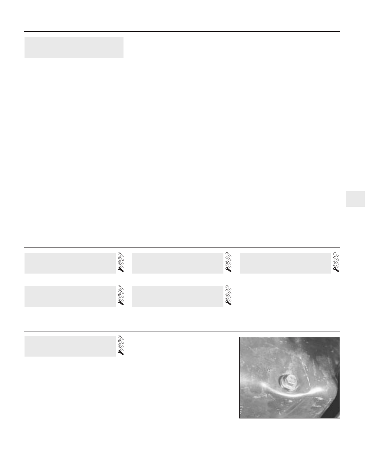
remains level, or if it is at an angle, so that the
drain plug is at the lowest point (see
illustration).
8 Engine oil and filter renewal
Maintenance procedures 1•9
1
8.2 Sump drain plug location
Every 250 miles (400 km) or weekly
Every 6000 miles (10 000 km) or 6 months
Page 28
3 Slacken the drain plug about half a turn.
Position the draining container under the drain
plug, then remove the plug completely. If
possible, try to keep the plug pressed into the
sump while unscrewing it by hand the last
couple of turns. As the plug releases from the
threads, move it away sharply so the stream
of oil issuing from the sump runs into the
container, not up your sleeve! Recover the
sealing washer from the drain plug.
4 Allow some time for the old oil to drain,
noting that it may be necessary to reposition
the container as the oil flow slows to a trickle.
5 After all the oil has drained, wipe off the
drain plug with a clean rag. Check the sealing
washer for condition, and renew it if
necessary. Clean the area around the drain
plug opening, and refit the plug. Tighten the
plug to the specified torque.
6 Move the container into position under the
oil filter.
7 Using an oil filter removal tool if necessary,
slacken the filter initially, then unscrew it by
hand the rest of the way (see illustration).
Empty the oil from the old filter into the
container, and discard the filter.
8 Use a clean rag to remove all oil, dirt and
sludge from the filter sealing area on the
engine. Check the old filter to make sure that
the rubber sealing ring hasn’t stuck to the
engine. If it has, carefully remove it.
9 Apply a light coating of clean engine oil to
the sealing ring on the new filter, then screw it
into position on the engine. Tighten the filter
firmly by hand only - do not use any tools.
Wipe clean the filter and sump drain plug.
10 Remove the old oil and all tools from
under the car, then lower the car to the
ground (if applicable).
11 Remove the oil filler cap and withdraw the
dipstick. Fill the engine, using the correct
grade and type of oil (see “Lubricants and
fluids”). An oil can spout or funnel may help to
reduce spillage. Pour in half the specified
quantity of oil first, then wait a few minutes for
the oil to fall to the sump. Continue adding oil
a small quantity at a time until the level is up to
the lower mark on the dipstick. Finally, bring
the level up to the upper mark on the dipstick.
Insert the dipstick, and refit the filler cap.
12 Start the engine and run it for a few
minutes; check for leaks around the oil filter
seal and the sump drain plug. Note that there
may be a delay of a few seconds before the oil
pressure warning light goes out when the
engine is first started, as the oil circulates
through the engine oil galleries and the new oil
filter, before the pressure builds up.
13 Switch off the engine, and wait a few
minutes for the oil to settle in the sump once
more. With the new oil circulated and the filter
completely full, recheck the level on the
dipstick, and add more oil as necessary.
14 Dispose of the used engine oil safely, with
reference to “General repair procedures” in
the Reference section of this manual.
1 Firmly apply the handbrake, then jack up
the front and rear of the car and support it
securely on axle stands (see “Jacking and
vehicle support”).
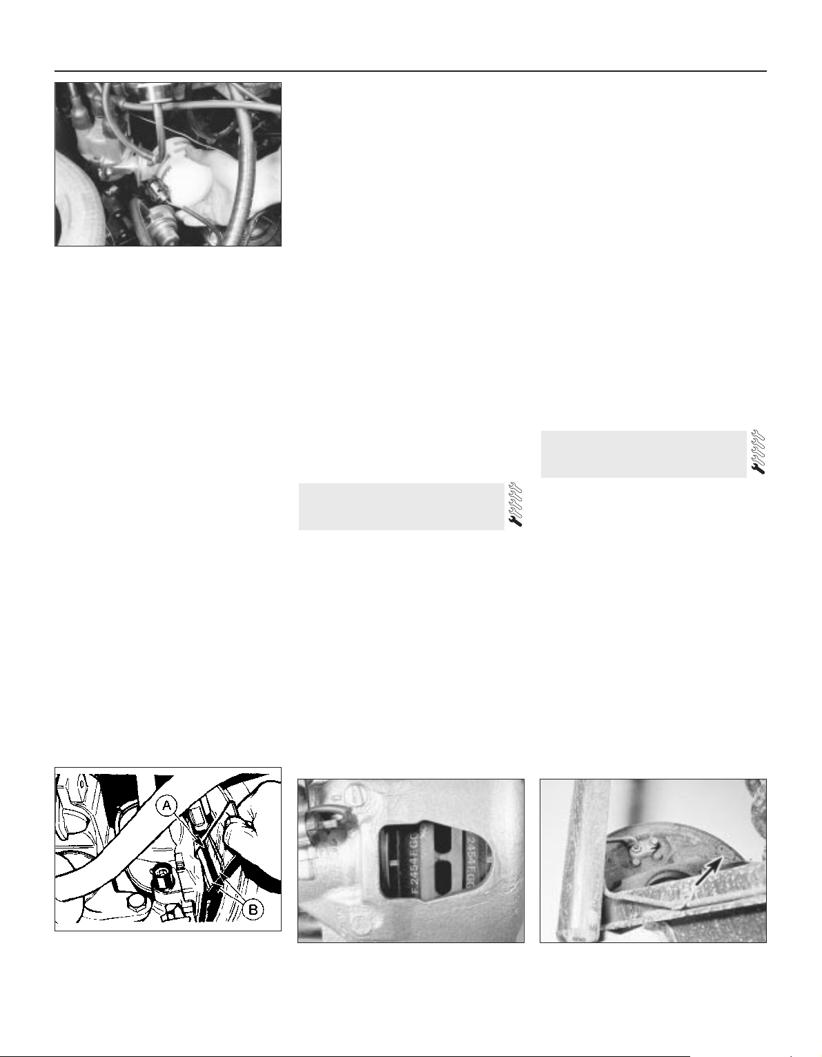
2 For a quick check, the front brake disc pads
can be inspected without removing the front
wheels by inserting a mirror between each
caliper and roadwheel (see illustration). If any
one pad is worn down to the minimum
specified thickness, all four pads (on both
front wheels) must be renewed.
3 It is necessary to remove the rear wheels in
order to inspect the rear disc pads. The pads
can be viewed through the top of the caliper
after removing the blanking spring clip (see
illustration). If any one pad is worn down to
the minimum specified, all four pads (on both
rear wheels) must be renewed.
4 For a comprehensive check, the brake disc
pads should be removed and cleaned. The
operation of the caliper can then also be
checked, and the condition of the brake discs
can be fully examined on both sides. Refer to
Chapter 10 for further information.
5 On rear drum brake models, the brake shoe
friction material can be inspected for wear
without removing the roadwheels. Working
beneath the vehicle, prise the plug from the
brake backplate, and using an inspection
lamp or torch, check that the friction material
thickness is not less than the minimum given
in the Specifications (see illustration). If any
one of the shoes has worn below the
specified limit, the shoes must be renewed as
an axle set (4 shoes).
6 At the same interval, check the function of the
brake fluid level warning light. Chock the wheels,
release the handbrake and switch on the
ignition. Unscrew and raise the brake fluid
reservoir cap whilst an assistant observes the
warning light: it should come on as the level
sensor is withdrawn from the fluid. Refit the cap.
7 On completion, refit the wheels and lower
the car to the ground.
1 Visually inspect the engine joint faces,
gaskets and seals for any signs of water or oil
leaks. Pay particular attention to the areas
around the rocker cover, cylinder head, oil
filter and sump joint faces. Bear in mind that
over a period of time some very slight
seepage from these areas is to be expected
but what you are really looking for is any
indication of a serious leak. Should a leak be
found, renew the offending gasket or oil seal
by referring to the appropriate Chapter(s) in
this manual.
2 Similarly, check the transmission for oil
leaks, and investigate and rectify and
problems found.
3 Check the security and condition of all the
engine related pipes and hoses. Ensure that
all cable-ties or securing clips are in place and
in good condition. Clips which are broken or
missing can lead to chafing of the hoses,
pipes or wiring which could cause more
serious problems in the future.
10 Fluid leak check
9 Front and rear brake pad/shoe
check
1•10 Every 6000 miles or 6 months
8.7 Unscrewing the oil filter
9.3 Disc pads viewed through caliper
inspection hole (roadwheel removed)
9.5 Brake shoe inspection hole plug
(arrowed)
9.2 Using a mirror to inspect the disc pad
friction material for wear
A Brake disc B Brake disc pads
Page 29
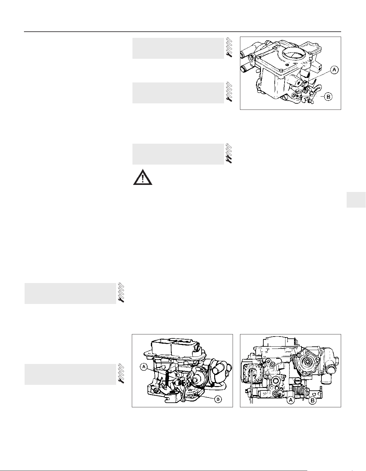
4 Carefully check the condition of all coolant,
fuel, power steering and brake hoses. Renew
any hose which is cracked, swollen or
deteriorated. Cracks will show up better if the
hose is squeezed. Pay close attention to the
hose clips that secure the hoses to the system
components. Hose clips can pinch and
puncture hoses, resulting in leaks. If wire type
hose clips are used, it may be a good idea to
replace them with screw-type clips.
5 With the vehicle raised, inspect the fuel
tank and filler neck for punctures, cracks and
other damage. The connection between the
filler neck and tank is especially critical.
Sometimes a rubber filler neck or connecting
hose will leak due to loose retaining clamps or
deteriorated rubber.
6 Similarly, inspect all brake hoses and metal
pipes. If any damage or deterioration is
discovered, do not drive the vehicle until the
necessary repair work has been carried out.
Renew any damaged sections of hose or pipe.
7 Carefully check all rubber hoses and metal
fuel lines leading away from the petrol tank.
Check for loose connections, deteriorated
hoses, crimped lines and other damage. Pay
particular attention to the vent pipes and
hoses which often loop up around the filler
neck and can become blocked or crimped.
Follow the lines to the front of the vehicle
carefully inspecting them all the way. Renew
damaged sections as necessary.
8 From within the engine compartment,
check the security of all fuel hose attachments
and pipe unions, and inspect the fuel hoses
and vacuum hoses for kinks, chafing and
deterioration.
9 Where applicable, check the condition of
the oil cooler hoses and pipes.
10 Check the condition of all exposed wiring
harnesses.
1 Periodically check the belts for fraying or
other damage. If evident, renew the belt.
2 If the belts become dirty, wipe them with a
damp cloth using a little detergent only.
3 Check the tightness of the anchor bolts and
if they are ever disconnected, make quite sure
that the original sequence of fitting of
washers, bushes and anchor plates is
retained.
With the vehicle raised on a hoist or
supported on axle stands, check the exhaust
system for signs of leaks, corrosion or
damage and check the rubber mountings for
condition and security. Where damage or
corrosion are evident, renew the system
complete or in sections, as applicable, using
the information given in Chapter 4.
With the wheels on the ground, slacken each
wheel nut by a quarter turn, then retighten it
immediately to the specified torque.
Remove and clean the oil filler cap of any
sludge build-up using paraffin.
Inspect the vent hose for blockage or
damage. A blocked hose can cause a buildup of crankcase pressure, which in turn can
cause oil leaks.
Ford VV carburettor
1 Ensure that the air cleaner is correctly fitted,
and that all vacuum hoses and pipes are
securely connected and free from restrictions,
then run the engine until it is at normal
operating temperature.
2 Stop the engine, and connect a tachometer
and an exhaust gas analyser in accordance
with the manufacturer’s instructions.
3 Start the engine and run it at 3000 rpm for
30 seconds, ensuring that all electrical loads
are switched off (headlamps, heater blower
etc), then allow the engine to idle and check
the idle speed and CO content. Note that the
CO reading will initially rise, then fall and finally
stabilise after between 5 and 25 seconds.
4 If necessary, adjust the idle speed screw to
give the specified idle speed (see
illustration).
5 Checking and adjustment should be
completed within 30 seconds of the meter
readings stabilising. If this has not been
possible, repeat paragraphs 3 and 4, ignoring
the reference to starting the engine.
Weber 2V carburettor
Models without stepper motor
6 Proceed as described for the Ford VV
carburettor but note the following:
7 It is permissible to loosen the air cleaner
securing screws to allow easier access to the
carburettor adjustment screws but ensure
that all vacuum hoses and pipes are securely
connected. For adjustment screw location
(see illustrations).
Models with stepper motor (ESC II
system)
8 The idle speed is controlled by the ESC II
module via the stepper motor. The only idle
speed adjustment possible is provided by the
“idle speed adjustment” wire, which can be
earthed to raise the idle speed by 75 rpm. No
other method of idle speed adjustment should
be attempted. If the idle speed is incorrect,
the problem should be referred to a Ford
dealer, as the problem probably lies in the
ESC II module for which special diagnostic
equipment is required.
15 Engine idle speed check
14 Oil filler cap check
13 Roadwheel security check
12 Exhaust system check
11 Seat belt check
Every 6000 miles or 6 months 1•11
1
15.7b Weber 2V carburettor adjustment
screw locations - 1.6 litre models
A Idle mixture screw B Idle speed screw
15.7a Weber 2V carburettor adjustment
screw locations - 2.0 litre models up to 1985
A Idle speed screw B Idle mixture screw
15.4 Ford VV carburettor adjustment screw
locations
A Idle speed screw B Idle mixture screw
Caution: Refer to the
precautions in Section 1,
Chapter 4, Part A or B (as
applicable), before proceeding.
Before carrying out any carburettor
adjustments, ensure that the ignition
timing and spark plug gaps are set as
specified. To carry out the adjustments an
accurate tachometer and an exhaust gas
analyser (CO meter) will be required.
Page 30
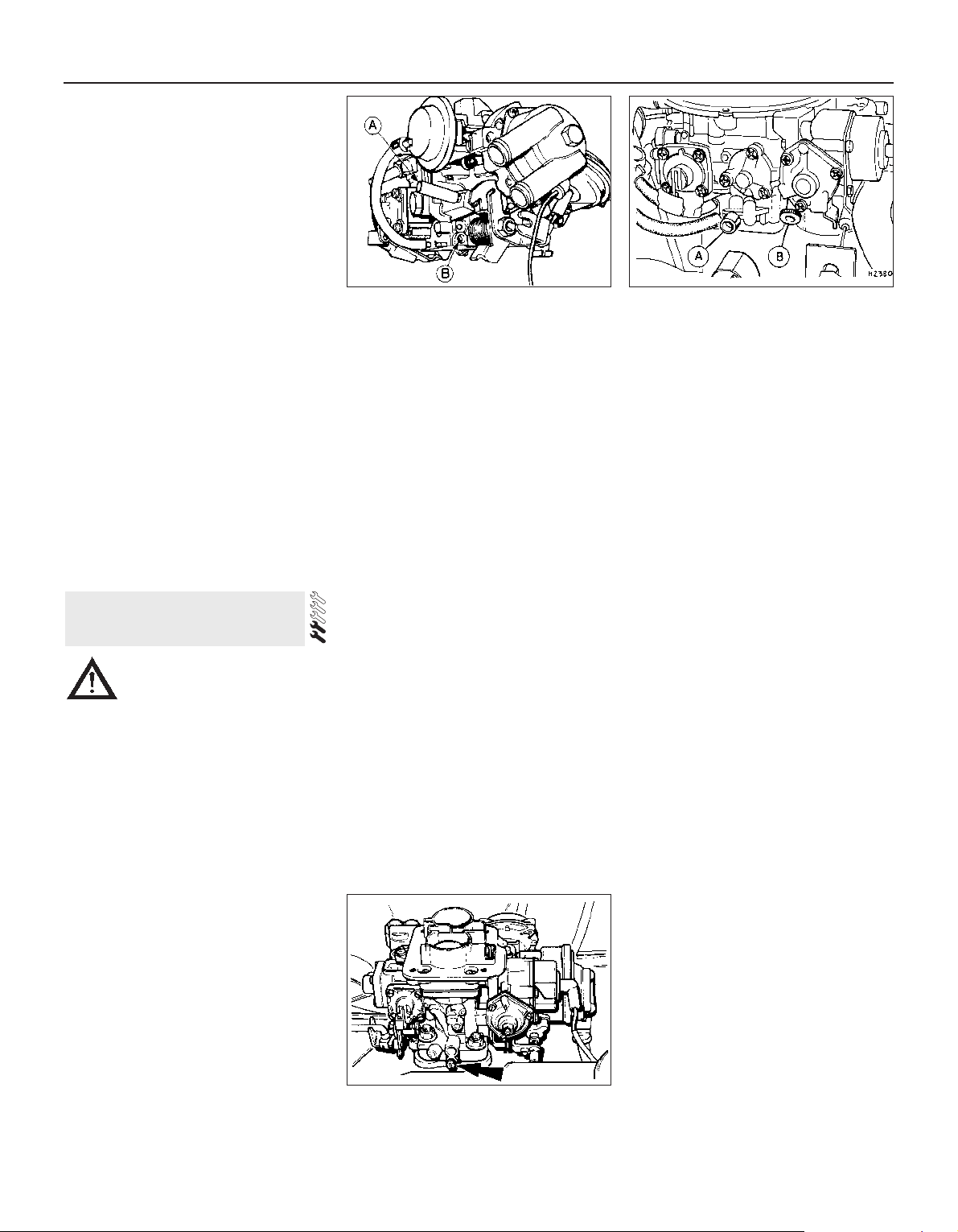
Pierburg 2V carburettor
9 Proceed as described for the Ford VV
carburettor. For adjustment screw location
(see illustration).
Weber 2V TLD carburettor
10 Proceed as described for the Ford VV
carburettor, noting the following points:
11 Ensure that the vacuum pipe and the
camshaft cover breather hose are securely
connected to the air cleaner and are free from
restrictions.
12 When warming-up the engine, run the
engine until the cooling fan cuts in.
13 For adjustment screw location (see
illustration).
Fuel injection
2.0 litre SOHC models
14 Idle speed is controlled by the EEC IV
module and the only means of adjustment
provided is by the yellow “idle speed
adjustment” wire (Chapter 5, Section 17) which
allows the idle speed to be raised by 75 rpm.
2.0 litre DOHC models
15 Idle speed is controlled by the EEC IV
module, and manual adjustment is not
possible.
16 The “base” idle speed can be adjusted,
but only by a Ford dealer, using special
equipment.
Ford VV carburettor
1 Ensure that the air cleaner is correctly fitted
and that all vacuum hoses and pipes are
securely connected and free from restrictions,
then run the engine until it is at normal
operating temperature.
2 Stop the engine, and connect a tachometer
and an exhaust gas analyser in accordance
with the manufacturer’s instructions.
3 Start the engine and run it at 3000 rpm for 30
seconds, ensuring that all electrical loads are
switched off (headlamps, heater blower etc),
then allow the engine to idle and check the idle
speed and CO content. Note that the CO
reading will initially rise, then fall and finally
stabilise after between 5 and 25 seconds.
4 If the reading noted in paragraph 3 is not as
specified, proceed as follows.
5 Using a thin screwdriver, remove the
tamperproof seal from the mixture screw.
6 Run the engine at 3000 rpm for 30 seconds,
then allow the engine to idle, and using a
small screwdriver or a 4.0 mm Allen key, as
applicable, adjust the mixture screw to give
the specified CO content.
7 Checking and adjustment should be
completed within 30 seconds of the meter
readings stabilising. If this has not been
possible, then repeat paragraph 6.
8 If necessary adjust the idle speed, then
recheck the CO content.
9 On completion of the adjustments, stop the
engine and disconnect the tachometer and
exhaust gas analyser. Fit a new tamperproof
seal to the mixture screw.
Weber 2V carburettor
Models without stepper motor
10 Proceed as described for the Ford VV
carburettor but note the following:
11 To remove the mixture screw tamperproof
seal, it will be necessary to drill the seal in
order to prise it from the mixture screw
housing. Alternatively a self-tapping screw
can be used to draw out the seal. If the
tamperproof seal is to be renewed, ensure
that a blue-coloured replacement seal is
fitted.
12 It is permissible to loosen the air cleaner
securing screws to allow easier access to the
carburettor adjustment screws, but ensure
that all vacuum hoses and pipes are securely
connected.
Models with stepper motor (ESC II
system)
13 If necessary, the mixture can be adjusted
as described for the Ford VV carburettor with
reference to paragraphs 11 and 12 of this
Section. Do not attempt to adjust the idle
speed on completion of mixture adjustment.
For adjustment screw location (see
illustration).
Pierburg 2V carburettor
14 Proceed as described for the Ford VV
carburettor.
Weber 2V TLD carburettor
15 Proceed as described for the Ford VV
carburettor, noting the following points:
16 Ensure that the vacuum pipe and the
camshaft cover breather hose are securely
connected to the air cleaner and are free from
restrictions.
17 When warming-up the engine, run the
engine until the cooling fan cuts in.
18 If adjustment of the mixture (CO content)
is required, the air cleaner must be removed
for access to the adjustment screw, as
follows.
19 Remove the air cleaner, and prise the
tamperproof seal from the mixture screw.
20 Loosely refit the air cleaner, ensuring that
the vacuum pipe and the camshaft cover
breather hose are securely connected and
free from restrictions (there is no need to
secure the air cleaner in position).
21 On completion, fit a new tamperproof seal
to the mixture screw (the service replacement
plug is coloured blue), and refit the air cleaner
assembly.
Fuel injection
2.0 litre SOHC models
22 The idle mixture can be checked and if
necessary adjusted as follows:
23 Run the engine until it is at normal
operating temperature.
24 Stop the engine and connect a
tachometer and an exhaust gas analyser in
accordance with the manufacturer’s
instructions.
16 Mixture adjustment check
1•12 Every 6000 miles or 6 months
15.9 Pierburg 2V carburettor adjustment
screw locations
A Idle speed screw B Idle mixture screw
A Idle mixture screw B Idle speed screw
16.13 Weber 2V carburettor idle mixture
adjustment screw location (arrowed) -
2.0 litre models from 1985
15.13 Weber 2V TLD carburettor
adjustment screw locations
Caution: Refer to the
precautions in Section 1,
Chapter 4, Part A or B (as
applicable), before proceeding.
Before carrying out any carburettor
adjustments, ensure that the ignition
timing and spark plug gaps are set as
specified. To carry out the adjustments an
accurate tachometer and an exhaust gas
analyser (CO meter) will be required.
Page 31

25 Start the engine and run it at 3000 rpm for
15 seconds, ensuring that all electrical loads
(headlamps, heater blower etc) are switched
off, then allow the engine to idle and check
the CO content. Note that the CO reading will
initially rise, then fall and finally stabilise.
26 If adjustment is necessary, remove the
tamperproof cap from the base of the airflow
meter, and turn the mixture screw using a
suitable Allen key to give the specified CO
content (see illustration).
27 Checking and adjustment should be
completed within 30 seconds of the meter
readings stabilising. If this has not been
possible, run the engine at 3000 rpm, for 15
seconds, then allow the engine to idle. Recheck the CO content and carry out further
adjustment if necessary.
28 On completion of adjustment, stop the
engine and disconnect the tachometer and
exhaust gas analyser. Fit a new tamperproof
cap to the mixture screw.
2.0 litre DOHC models
29 On models with a catalytic converter, the
mixture is controlled by the EEC IV module.
No manual adjustment is possible.
30 On models without a catalytic converter,
the idle mixture can be adjusted as follows:
31 Run the engine until it is at normal
operating temperature.
32 Stop the engine, and connect a
tachometer and an exhaust gas analyser in
accordance with the equipment
manufacturer’s instructions.
33 Start the engine and run it at 3000 rpm for
15 seconds, ensuring that all electrical loads
(headlamps, heater blower, etc) are switched
off. Allow the engine to idle, and check the CO
content. Note that the reading will initially rise,
then fall and finally stabilise.
34 If adjustment is necessary, remove the
cover from the mixture adjustment
potentiometer (located at the rear right-hand
side of the engine compartment, behind the
MAP sensor), and turn the screw to give the
specified CO content (see illustrations).
35 If adjustment does not produce a change
in reading, the potentiometer may be at the
extreme of its adjustment range. To centralise
the potentiometer, turn the adjustment screw
20 turns clockwise followed by 10 turns anticlockwise, then repeat the adjustment procedure.
36 Checking and adjustment should be
completed within 30 seconds of the meter
readings stabilising. If this has not been
possible, run the engine at 3000 rpm for 15
seconds, then allow the engine to idle. Recheck the CO content, and carry out further
adjustments if necessary.
37 On completion of adjustment, stop the
engine, and disconnect the tachometer and
the exhaust gas analyser. Refit the cover to
the adjustment screw.
1 Fluid level should be checked with the
transmission at operating temperature (after a
run) and with the vehicle parked on level
ground.
2 Open and prop the bonnet. With the engine
idling and the handbrake and footbrake applied,
move the gear selector through all positions
three times, finishing up in position “P”,
3 Wait one minute. With the engine still idling,
withdraw the transmission dipstick (see
illustration). Wipe the dipstick with a clean
lint-free rag, re-insert it fully and withdraw it
again. Read the fluid level at the end of the
dipstick: it should be between the two
notches.
4 If topping-up is necessary, do so via the
dipstick tube, using clean transmission fluid of
the specified type (see illustration). Do not
overfill.
5 Stop the engine, refit the dipstick and close
the bonnet.
6 Note that if the fluid level was below the
minimum mark when checked or is in
constant need of topping-up, check around
the transmission for any signs of excessive
fluid leaks.If present, leaks must be rectified
without delay.
7 If the colour of the fluid is dark brown or
black this denotes the sign of a worn brake
band or transmission clutches, in which case
have your Ford dealer check the transmission
at the earliest opportunity.
1 Place the vehicle over a pit, or raise and
support it at front and rear. The vehicle must
be level for an accurate check.
2 If the gearbox is hot after a run, allow it to
cool for a few minutes. This is necessary
because the oil can foam when hot and give a
false level reading.
18 Manual gearbox oil level
check
17 Automatic transmission fluid
level check
Every 12 000 miles or 12 months 1•13
1
16.34b . . . to enable mixture adjustment DOHC models
17.4 Topping-up the transmission fluid17.3 Automatic transmission dipstick
location and markings
16.34a Remove the cover from the mixture
adjustment potentiometer . . .
16.26 Adjusting the idle mixture SOHC models
Every 12 000 miles (20 000 km) or 12 months
Page 32

3 Wipe clean around the filler/level plug.
Unscrew the plug and remove it (see
illustration).
4 Using a suitably marked piece of bent wire
as a dipstick, check that the oil level is as
shown in the table at the top of this page,
according to gearbox type.
5 Top-up the level if necessary, using clean
oil of the specified type. Do not overfill, as this
can lead to leakage and difficult gear
changing. Allow excess oil to drip out of the
filler/level hole if necessary. Refit and tighten
the filler/level plug on completion.
6 The frequent need for topping-up can only
be due to leaks, which should be rectified.
The most likely sources of leaks are the rear
extension housing and input shaft oil seals.
7 No periodic oil changing is specified, and
no drain plug is fitted.
1 Work around the vehicle, and lubricate the
bonnet, door and tailgate hinges with a light
machine oil.
2 Lightly lubricate the bonnet release
mechanism and exposed sections of inner
cable with a smear of grease.
3 Check the security and operation of all
hinges, latches and locks, adjusting them
where required. Where applicable, check the
operation of the central locking system.
4 Check the condition and operation of the
tailgate struts, renewing them if either is
leaking or is no longer able to support the
tailgate securely when raised.
1 The correct functioning of the spark plugs is
vital for the correct running and efficiency of
the engine. It is essential that the plugs fitted
are appropriate for the engine.
2 Make sure that the ignition is switched off
before inspecting the HT leads to see if they
carry their cylinder numbers. Note that the
position of No 1 cylinder HT lead in the
distributor cap is marked with either a pip, or
a number “1 “.
3 Where necessary, for improved access
remove the air cleaner and/or the inlet hose.
4 Disconnect the leads from the plugs by
pulling on the connectors, not the leads.
5 On 2.0 litre DOHC carburettor models, the
location of the spark plugs and the close
proximity of the carburettor makes spark plug
access difficult, particularly when removing
the plugs from cylinders 2 and 3. It is
suggested that a 3/8 inch ratchet drive spark
plug socket with rubber insert and long
extension bar is used, possibly in conjunction
with a universal joint adapter. It is also
advisable to disconnect No 3 cylinder HT lead
from the distributor first, to allow some slack
for disconnection at the spark plug.
6 Clean the area around each spark plug
using a small brush, then using a plug
spanner (preferably with a rubber insert),
unscrew and remove the plugs (see
illustration). Cover the spark plug holes with
a clean rag to prevent the ingress of any
foreign matter.
7 Before fitting new spark plugs, check that
the threaded connector sleeves are tight. As
the plugs incorporate taper seats, make sure
that the threads and seats are clean.
8 On DOHC models before refitting the spark
plugs, coat their threads with suitable antiseize compound, taking care not to
contaminate the electrodes.
9 Screw in the spark plugs by hand, then
tighten them to the specified torque. Do not
exceed the torque figure.
10 Push the HT leads firmly onto the spark
plugs, and where applicable refit the air
cleaner and/or inlet hose.
1 Refer to the Specifications at the beginning
of this Chapter and check the tension of each
drivebelt at the point stated. Check the full
length of each drivebelt for cracks and
deterioration. It will be necessary to turn the
engine in order to check that portion of the
drivebelt in contact with the pulleys. Renew or
tension each belt as necessary as follows,
according to model type:
SOHC models
2 Note that two drivebelts are fitted to models
equipped with power steering and both
should be renewed if either one is
unserviceable. Where fitted, the air
conditioning compressor is driven by a
separate belt.
3 Disconnect the battery negative lead.
4 Where applicable, remove the air
conditioning compressor drivebelt.
5 Loosen the alternator mounting and
adjustment nuts and bolts, and pivot the
alternator towards the cylinder block.
6 Slip the drivebelt(s) from the alternator,
water pump, crankshaft and (where
applicable) the power steering pump pulleys.
7 Fit the new drivebelt(s) over the pulleys,
then lever the alternator away from the
cylinder block until the specified belt tension
is achieved. Lever the alternator using a
wooden or plastic lever at the pulley end to
prevent damage and straining the brackets. It
is helpful to partially tighten the adjustment
link bolt before tensioning the drivebelt(s).
21 Auxiliary drivebelt check
20 Spark plug renewal
19 Hinge and lock check and
lubrication
1•14 Every 12 000 miles or 12 months
18.3 Gearbox filler/level plug location
(arrowed) - N type gearbox
20.6 Removing a spark plug - CVH engine
Note: The vehicle build code appears as the twelfth and thirteenth characters of the VIN number
on the plate in the engine compartment.
Gearbox type
All four-speed gearboxes
All five-speed gearboxes up to April 1984 (build
code E6) except those subsequently fitted with
a modified extension housing
All five-speed gearboxes from May 1984 (build
code EC) to end of April 1985 (build code FP)
and all vehicles built up to April 1984 (build
code E6) subsequently fitted with a modified
gearbox extension housing
All five-speed gearboxes from May 1985
Oil level
0 to 5.0 mm (0 to 0.2 in) below lower edge of
filler/level hole
Level with bottom edge of filler/level hole
20.0 to 25.0 mm (0.79 to 0.99 in) below lower
edge of filler/level hole
0 to 5.0 mm (0 to 0.2 in)below lower edge of
filler/level hole
Number each HT lead using
sticky tape or paint before
removal so as to avoid
confusion when refitting.
Page 33

8 Tighten the alternator mounting and
adjustment nuts and bolts in the order shown
(see illustration).
9 Where applicable, refit and tension the air
conditioning compressor drivebelt.
10 Reconnect the battery negative lead.
11 Drivebelt tension should be rechecked
and if necessary adjusted after the engine has
been run for a minimum of ten minutes.
DOHC models
12 Three different types of drivebelt
arrangement are used, depending on model
(see illustrations). On models without power
steering, the drivebelt is tensioned by moving
the alternator. On models with power steering,
the power steering pump is also driven by the
coolant pump/alternator drivebelt and an
automatic belt tensioner is fitted (see
illustration). On models with air conditioning,
the drivebelt drives the alternator, coolant
pump, power steering pump and air
conditioning compressor, and an automatic
belt tensioner is fitted.
13 On models without power steering, loosen
the alternator mounting and adjustment bolts,
and pivot the alternator towards the cylinder
block. Slip the drivebelt from the pulleys.
14 On models with power steering, the
automatic tensioner can be released using a
17 mm socket and a wrench on the boss in
the centre of the pulley. Lever the tensioner
assembly clockwise, slide the belt from the
pulleys, then slowly release the tensioner.
15 To fit a new belt on models without
power steering, slide the belt over the pulleys,
then lever the alternator away from the
cylinder block until the correct belt tension is
achieved. Lever the alternator using a plastic
or wooden lever at the pulley end to prevent
damage. It is helpful to partially tighten the
adjustment link bolt before tensioning the
drivebelt. When the correct tension is
achieved, tighten all the bolts.
16 To fit a new belt on models with power
steering, lever the tensioner clockwise as
during removal, then slide the belt over the
pulleys, and slowly release the tensioner.
1 The battery fitted as original equipment is
“maintenance-free”, and requires no
maintenance apart from having the case kept
clean, and the terminals clean and tight.
2 To clean the battery terminals disconnect
them, after having first removed the cover
(later models) - negative earth first. Use a wire
brush or abrasive paper to clean the
terminals. Bad corrosion should be treated
with a solution of bicarbonate of soda, applied
with an old toothbrush. Do not let this solution
get inside the battery.
3 Coat the battery terminals with petroleum
jelly or a proprietary anti-corrosive compound
before reconnecting them. Reconnect and
tighten the positive (live) lead first, followed by
the negative (earth) lead. Do not overtighten.
4 Keep the top of the battery clean and dry.
Inspect the battery tray for corrosion, and
make good as necessary.
SOHC engines
1 The valve clearances must be checked with
the engine cold. On carburettor models
remove the air cleaner.
2 Disconnect the HT leads from the spark
plugs and release them from the clips on the
camshaft cover.
3 On fuel injection models, unbolt and
remove the bracing strut securing the inlet
manifold to the right-hand side of the cylinder
head.
4 Where applicable, unclip any hoses and
wires from the camshaft cover, then unscrew
the securing bolts and remove the camshaft
cover and gaskets. Take care not to lose the
spacer plates which fit under the bolt heads,
where applicable.
23 Engine valve clearance
check
22 Battery terminal check
Every 12 000 miles or 12 months 1•15
1
21.12b Coolant pump/alternator drivebelt
arrangement - 2.0 litre DOHC engine with
power steering
1 Alternator
2 Automatic belt
tension
3 Coolant pump
4 Crankshaft pulley
5 Power steering
pump
21.12d Alternator/coolant pump drivebelt
tensioner indicator position -
2.0 litre DOHC engine
Inset shows tensioner at maximum
adjustment
1 Alternator
2 Automatic belt
tensioner
3 Coolant pump
4 Air conditioning
compressor
5 Crankshaft pulley
6 Power steering
pump
21.12c Coolant pump/alternator drivebelt
arrangement - 2.0 litre DOHC engine with
power steering and air conditioning
21.12a Coolant pump/alternator drivebelt
arrangement - 2.0 litre DOHC engine
without power steering
1 Alternator
2 Coolant pump
3 Crankshaft
pulley
21.8 Alternator mounting tightening
sequence - SOHC engines
Caution: Before carrying out
any work on the vehicle battery,
read through the precautions
given in “Safety first!” at the
beginning of this manual.
It will be easier to turn the
engine by hand if the spark
plugs are removed but take
care not to allow dirt to enter
the spark plug holes.
Page 34

5 Numbering from the front (camshaft
sprocket) end of the engine, the exhaust
valves are 1, 3, 5 and 7, and the inlet valves
are 2, 4, 6 and 8.
6 Turn the engine clockwise using a suitable
socket on the crankshaft pulley bolt, until the
exhaust valve of No 1 cylinder (valve No 1) is
fully closed; ie the cam lobe is pointing
vertically upwards (see illustration).
7 Insert a feeler blade of the correct thickness
(see Specifications) between the cam follower
and the heel of the No 1 valve cam lobe. The
feeler blade should be a firm sliding fit. If not,
loosen the locknut and adjust the ball-pin
position accordingly by turning the adjuster
nut, then tighten the locknut (see
illustrations). Allowance must be made for
tightening the locknut, as this tends to
decrease the valve clearance. Recheck the
adjustment after tightening the locknut.
8 Repeat the procedure given in paragraphs
6 and 7 for the remaining valves. With the
carburettor/inlet manifold fitted, some difficulty may be experienced when adjusting the
exhaust valve clearances, and a suitable
open-ended spanner bent to 90º will be found
helpful.
9 Check the condition of the camshaft cover
gasket, and renew if necessary. Fit the gasket
to the camshaft cover ensuring that the
locating tabs and dovetails are correctly
located (see illustration), then refit the
camshaft cover and tighten the securing bolts
in the order shown (see illustration), ensuring
that the spacer plates are in position under
the bolt heads, where applicable.
10 On fuel injection models, refit the inlet
manifold bracing strut.
11 Where applicable refit the spark plugs.
Reconnect the HT leads and locate them in
the clips on the camshaft cover.
12 Where applicable, refit any wires and
hoses to the clips on the camshaft cover and
on carburettor models, refit the air cleaner.
DOHC and CVH engines
13 These engines are fitted with hydraulic
cam followers therefore no adjustment is
necessary.
Chock the front roadwheels and jack the
rear wheels clear of the ground, supporting
the vehicle with axlestands.
Check that with the handbrake released,
the rear wheels are free to rotate and no brake
“bind” is evident. The handbrake lever travel
should be between two and four clicks of the
ratchet. If brake “bind” or excessive lever
travel is evident, check the handbrake cable
routing and check the self-adjuster
mechanism for wear or damage. Refer to
Chapter 10 for full service information.
Gain access to the radiator matrix by
removing the surrounding body panels, fan
shrouds, etc. Clean dirt and debris from the
matrix using an air jet or water and a soft
brush. Be careful not to damage the fins or
cut your fingers.
Remove the protecting grille and clean any
leaves, insects etc. from the air conditioner
condenser coil and fins. Be very careful not to
damage the condenser fins: use a soft brush, or
a compressed air jet, along (not across) the fins.
1 If applicable, remove the radiator grille
being careful not to damage the condenser
fins.
2 Check the refrigerant charge as follows.
The engine should be cold and the ambient
temperature should be between 64° and 77°F
(18° and 25°C).
3 Start the engine and allow it to idle.
Observe the refrigerant sight glass (see
illustration) and have an assistant switch on
the air conditioning to fan speed III. A few
bubbles should be seen in the sight glass as
the system starts up, but all bubbles should
disappear within 10 seconds. Persistent
bubbles, or no bubbles at all, mean that the
refrigerant charge is low. Switch off the
26 Air conditioner refridgerant
charge check
25 Radiator matrix and air
conditioner condenser clean
24 Handbrake check
1•16 Every 12 000 miles or 12 months
23.6 Cam lobe correctly positioned for
checking valve clearance. Insert feeler
gauge as shown by arrow
23.7b Adjusting a valve clearance
26.3 Air conditioning system refrigerant
sight glass (arrowed)
23.9b Camshaft cover bolts (A) and spacer
plates (B)
Tighten bolts in following stages:
Stage 1 Bolts 1 to 6
Stage 2 Bolts 7 and 8
Stage 3 Bolts 9 and 10
Stage 4 Bolts 7 and 8 (again)
23.9a Camshaft cover gasket dovetails
23.7a Using a feeler gauge to check a
valve clearance
Page 35

system immediately if the charge is low and
do not use it again until it has been recharged.
4 Inspect the refrigerant pipes, hoses and
unions for security and good condition. Refit
the radiator grille.
5 The air conditioning system will lose a
proportion of its charge through normal
seepage typically up to 100 g (4 oz) per year so it is as well to regard periodic recharging
as a maintenance operation.
1 Check the final drive oil level as follows.
2 Position the vehicle over a pit, or raise it at
front and rear on ramps or axle stands. The
vehicle must be level.
3 Wipe clean around the final drive filler/level
plug (see illustrations) and unscrew the
plug. Using a piece of bent wire as a dipstick,
check that the oil is no more than 10 mm (0.4
in) below the plug hole.
4 If topping-up is necessary, use clean gear
oil of the specified type. Do not overfill.
Frequent need for topping-up can only be due
to leaks, which should be rectified.
5 When the level is correct, refit the filler/level
plug and tighten it to the specified torque
loading.
6 There is no requirement for periodic oil
changing, and no drain plug is provided.
Lubricate the transmission selector and
kickdown linkages with engine oil or aerosol
lubricant.
1 Check the shock absorbers by bouncing
the vehicle up and down at each corner in
turn. When released, it should come to rest
within one complete oscillation. Continued
movement, or squeaking and groaning noises
from the shock absorber suggests that
renewal is required .
2 Raise and support the vehicle. Examine all
steering and suspension components for
wear and damage. Pay particular attention to
dust covers and gaiters, which if renewed
promptly when damaged can save further
damage to the component protected.
3 At the same intervals, check the front
suspension lower arm balljoints for wear by
levering up the arms (see illustration).
Balljoint free movement must not exceed 0.5
mm (0.02 in). The track rod end balljoints can
be checked in a similar manner, or by
observing them whilst an assistant rocks the
steering wheel back and forth. If the lower arm
balljoint is worn, the complete lower arm must
be renewed .
4 Wheel bearings can be checked for wear by
spinning the relevant roadwheel. Any
roughness or excessive noise indicates worn
bearings, which must be renewed, as no
adjustment is possible. It is unlikely that any
wear will be evident unless the vehicle has
covered a very high mileage. It should be
noted that it is normal for the bearings to
exhibit slight endfloat, which is perceptible as
wheel rock at the wheel rim.
1 Position the vehicle over a pit, or raise it at
front and rear on ramps or axle stands (see
“Jacking and vehicle support”).
2 Examine the driveshaft joint rubber gaiters.
Flex the gaiters by hand and inspect the folds
and clips. Damaged or leaking gaiters must
be renewed without delay to avoid damage
occurring to the joint itself
3 Check the tightness of the final drive
mounting bolts and the driveshaft flange screws.
1 Except on vehicles with a wax-based
underbody protective coating, have the whole
of the underframe of the vehicle steamcleaned, engine compartment included, so
that a thorough inspection can be carried out
to see what minor repairs and renovations are
necessary.
2 Steam-cleaning is available at many
garages and is necessary for the removal of
the accumulation of oily grime which
sometimes is allowed to become thick in
certain areas. If steam-cleaning facilities are
not available, there are some excellent grease
solvents available which can be brushapplied; the dirt can then be simply hosed off.
3 After cleaning, position the vehicle over a
pit, or raise it at front and rear on ramps or axle
stands (see “Jacking and vehicle support”).
4 Using a strong light, work around the
underside of the vehicle, inspecting it for
corrosion or damage. If either is found, refer
to Chapter 12 for details of repair.
Periodically inspect the rigid brake pipes for
rust and other damage, and the flexible hoses
for cracks, splits or “ballooning”. Have an
assistant depress the brake pedal (ignition on)
and inspect the hose and pipe unions for leaks.
Renew any defective item without delay.
On carburettor models which incorporate a
stepper motor (ie. Weber 2V from 1985), good
electrical contact between the motor plunger
and the adjusting screw is essential to
maintain a regular idle speed.
Clean the plunger and adjusting screw
contact faces with abrasive paper followed by
switch cleaning fluid. Switch cleaning fluid is
available from electronic component shops.
Instruments and electrical
equipment
1 Check the operation of all instruments and
electrical equipment.
2 Make sure that all instruments read
correctly, and switch on all electrical
equipment in turn to check that it functions
properly.
34 Road test
33 Idle speed linkage clean
32 Brake pipe and hose check
31 Underbody inspection
30 Driveshaft check
29 Steering and suspension
security check
28 Automatic transmission
selector linkage lubrication
27 Final drive oil level check
Every 12 000 miles or 12 months 1•17
1
29.3 Levering up lower arm to check
balljoint for wear
27.3b Rear axle filler plug location P100 models
27.3a Final drive unit filler plug location
(arrowed) -
Saloon, Hatchback and Estate models
Page 36

Steering and suspension
3 Check for any abnormalities in the steering,
suspension, handling or road “feel”.
4 Drive the vehicle, and check that there are
no unusual vibrations or noises.
5 Check that the steering feels positive, with
no excessive “sloppiness”, or roughness, and
check for any suspension noises when
cornering, or when driving over bumps.
Drivetrain
6 Check the performance of the engine,
clutch, transmission and driveshafts.
7 Listen for any unusual noises from the
engine, clutch and transmission.
8 Make sure that the engine runs smoothly
when idling, and that there is no hesitation
when accelerating.
9 Where applicable, check that the clutch
action is smooth and progressive, that the
drive is taken up smoothly, and that the pedal
travel is not excessive. Also listen for any
noises when the clutch pedal is depressed.
10 Check that all gears can be engaged
smoothly, without noise, and that the gear lever
action is not abnormally vague or “notchy”.
Check the operation and
performance of the braking
system
11 Make sure that the vehicle does not pull to
one side when braking, and that the wheels
do not lock prematurely when braking hard.
12 Check that there is no vibration through
the steering when braking.
13 Check that the handbrake operates
correctly, without excessive movement of the
lever, and that it holds the vehicle stationary
on a slope.
14 Test the operation of the brake servo unit
as follows. With the engine off, depress the
footbrake four or five times to exhaust the
vacuum. Start the engine, holding the brake
pedal depressed. As the engine starts, there
should be a noticeable “give” in the brake
pedal as vacuum builds up. Allow the engine
to run for at least two minutes, and then
switch it off. If the brake pedal is depressed
now, it should be possible to detect a hiss
from the servo as the pedal is depressed.
After about four or five applications, no further
hissing should be heard, and the pedal should
feel considerably firmer.
1 Inspect the crankcase ventilation system
for blockage or damage. A blocked hose can
cause a build-up of crankcase pressure,
which in turn can cause oil leaks (see
illustration).
2 On carburettor model SOHC engines, clean
the oil filler cap with paraffin and check that
the vent valve is not blocked by pulling it from
the oil separator and loosening the hose clip
(Section 42).
3 On CVH engines, check that the oil
separator and mushroom valve are not
blocked, and clean if necessary (see
illustration).
35 Crankcase ventilation system
check
SOHC and DOHC carburettor
models
1 A vacuum pump will be required to test the
control components.
2 To check the operation of the air
temperature control, the engine must be cold.
First observe the position of the flap valve
which should be fully closed prior to starting
the engine (see illustration). The position of
the flap can be observed by disconnecting the
cold air inlet hose from the air cleaner spout
and looking into the spout.
3 Start the engine and allow it to idle. Check
that the flap is now fully open to admit hot air
from the exhaust manifold shroud. If the flap
does not fully open, stop the engine and
check the vacuum diaphragm unit and heat
sensor as follows (see illustrations).
4 Working under the base of the air cleaner
body, disconnect the diaphragm unit-to-heat
sensor vacuum pipe at the sensor end, and
connect a vacuum pump to the diaphragm unit.
Apply a vacuum of 100.0 mm (4.0 in) of mercury.
5 If the flap opens, then the heat sensor is
faulty and should be renewed. If the flap
remains closed, then the diaphragm unit is
faulty, and a new air cleaner body will have to
be obtained, as the diaphragm unit is not
available separately.
6 On completion of the checks, disconnect
the vacuum pump, and reconnect the vacuum
pipe and cold air inlet hose.
36 Air cleaner inlet air
temperature control check
1•18 Every 24 000 miles or 2 years
35.1 Loosening the crankcase ventilation
hose clip - CVH models
36.3b Air cleaner heat sensor viewed from
inside air cleaner - OHC models
36.3a Air cleaner vacuum diaphragm unit OHC models
36.2 Air cleaner flap valve operation OHC models
A Flap fully open to admit hot air
B Flap fully closed to admit cold air
35.3 Oil separator (1) and mushroom valve
(2) locations in air cleaner - CVH models
Every 24 000 miles (40 000 km) or 2 years
Page 37

CVH carburettor models
7 To test the unit the engine must initially be
cold. Disconnect the hot air inlet hose from
the air cleaner spout and observe the position
of the flap which should be fully open to allow
only hot air to enter (see illustration).
8 Refit the hose and warm up the engine to
normal operating temperature.
9 Disconnect the hot air inlet hose again, and
observe the position of the flap which should
be fully closed to admit only cold air.
10 If the flap positions are not as described,
the waxstat is defective and the complete air
cleaner must be renewed as the waxstat is
not available separately.
11 On completion of the checks, stop the
engine and reconnect the hot air inlet hose.
1 The pulse-air filter is located at the front
left-hand side of the engine compartment.
2 To renew the element, simply unclip the
filter cover, then lift out the metal gauze, and
withdraw the filter element (see illustration).
3 Refitting is a reversal of removal. Ensure
that the holes in the gauze and the filter
element are positioned on the engine side of
the filter housing.
Carburettor models
1 Remove the screws from the top of the air
cleaner cover (see illustration).
2 Where applicable release the spring clips
around the edge of the cover, then lift or prise
off the cover (see illustration).
3 Lift out the air cleaner element. Wipe the
inside of the air cleaner body clean, taking
care not to allow dirt to enter the carburettor
throat. Also clean the inside of the cover.
4 Place a new element in position, then refit
the air cleaner cover.
Fuel-injection models
All models except 2.0 litre DOHC
5 Disconnect the battery negative lead.
6 Depress the locking clip on the airflow
meter wiring plug and disconnect the plug.
Pull on the plug, not the wiring (see
illustration).
7 Loosen the securing clip and disconnect
the air inlet hose from the airflow meter.
8 Release the four securing clips and lift off
the air cleaner lid with the airflow meter.
9 Lift out the old air cleaner element (see
illustration), then wipe the inside of the air
cleaner casing and lid clean.
10 Fit the new element with the sealing lip
uppermost.
11 Refit the air cleaner lid and secure with
the four clips.
12 Reconnect the air inlet hose to the airflow
meter, ensuring that the securing clip is
correctly aligned (see illustration). Reconnect
the wiring plug.
38 Air cleaner element renewal
37 Pulse air filter element
renewal (1.6 litre CVH)
Every 24 000 miles or 2 years 1•19
1
37.2 Withdrawing the pulse-air filter
element and gauze - 1.6 litre CVH models
38.12 Air intake hose clip correctly aligned38.9 Unclip the lid and remove the air
cleaner element
38.6 Disconnecting the airflow meter
wiring plug
38.2 . . . release the spring clips, and lift off
the cover for access to the element
38.1 Remove the air cleaner cover
screws . . .
36.7 Air cleaner flap valve operation - CVH models
A Flap fully open to admit hot air
B Flap fully closed to admit cold air
1 Air inlet spout
2 Hot air inlet hose
3 Flap valve
4 Link arm
5 Waxstat
6 Air cleaner body
Page 38

13 Reconnect the battery negative lead.
2.0 litre DOHC models
14 Disconnect the battery negative lead.
15 Disconnect the wiring plug from the idle
speed control valve at the front of the plenum
chamber.
16 Loosen the clamp, and detach the air inlet
hose from the air inlet tubing.
17 Unscrew the securing nut, and release the
air inlet tube from the bracket on the engine
compartment front panel (see illustration).
18 Release the air cleaner lid securing clips,
then lift away the air inlet tube, plenum
chamber and air cleaner lid as an assembly,
disconnecting the breather hose from the air
inlet tube.
19 Lift out the air cleaner element (see
illustration), then wipe the inside of the air
cleaner lid and casing clean.
20 Fit the new element with the sealing lip
uppermost.
21 Further refitting is a reversal of removal.
1 Before disturbing any part of the ignition
system, disconnect the battery negative lead.
2 Identify and clearly mark all HT leads before
disconnecting them from the spark plugs.
3 Refer to the appropriate Section in Chapter
5 and, where applicable, remove the
distributor cap and rotor arm.
4 Clean the HT leads and distributor cap with
a dry cloth. Scrape any corrosion or other
deposits from the connectors and terminals.
Also clean the coil tower.
5 Renew the HT leads if they are cracked,
burnt or otherwise damaged. If a multi-meter
is available, measure the resistance of the
leads. The desired value is given in the
Specifications of Chapter 5.
6 Renew the distributor cap if it is cracked or
badly burnt inside, or if there is evidence of
“tracking” (black lines marking the path of HT
leakage). If there is a carbon brush at the
centre of the cap, make sure that it moves
freely, and is not excessively worn (see
illustration).
7 Clean the metal track of the rotor arm with
fine abrasive paper. Renew the arm if it is
cracked or badly burnt.
8 Refit the rotor arm and distributor cap.
9 Reconnect the HT leads to the spark plugs
and coil.
10 Reconnect the battery and run the engine.
Note: A brake band torque wrench - Ford tool
No 17-005, or a conventional torque wrench
and a splined socket of suitable size to fit the
square section head of the adjuster screw(s)
will be required for this operation.
1 For improved access, apply the handbrake,
then jack up the front of the vehicle and
support on axle stands (see “Jacking and
vehicle support”).
2 The brake band adjuster screw(s) is/are
situated on the left-hand side of the
transmission housing, forward of the
kickdown lever. Note that the C3 type
transmission has a single adjuster screw for
adjustment of the front brake band, whereas
the A4LD type transmission has two adjuster
screws for adjustment of the front and
intermediate brake bands (see illustration).
3 Disconnect the kickdown cable from the
kickdown lever on the transmission housing.
4 Loosen the locknut on the front brake band
adjuster screw, and back off the adjuster
screw several turns.
5 Using the Ford special tool or a suitable
equivalent, tighten the adjuster screw to the
specified torque, then back off the screw two
complete turns, and tighten the locknut.
Ensure that the adjuster screw does not turn
as the locknut is tightened.
6 Repeat the procedure given in paragraphs
4 and 5 for the remaining adjuster screw on
A4LD type transmissions, but on all models
where the part number on the transmission
identification tag starts with “88” (see
illustration) and additionally on all 1.8 CVH
engine models, the adjuster screw should be
backed off two and a half turns after
tightening to the specified torque. On all other
models, the adjuster screw should be backed
off two turns.
7 Reconnect the kickdown cable, and lower
the vehicle to the ground on completion.
2.0 litre SOHC fuel injection
models
1 The fuel filter is located on the left-hand
side of the engine compartment (see
illustration).
2 Disconnect the battery negative lead.
3 Position a suitable container beneath the
filter, then slowly loosen the fuel inlet union to
relieve the pressure in the fuel lines.
4 Disconnect the fuel inlet and outlet unions.
Be prepared for petrol spillage. If necessary,
identify the fuel line unions for use when
refitting.
5 Loosen the filter clamp screw, and
withdraw the filter from the clamp. Drain the
petrol from the filter into the container.
Dispose of the filter carefully.
41 Fuel filter renewal
40 Automatic transmission
brake band adjustment
39 Ignition system component
check
1•20 Every 24 000 miles or 2 years
38.17 Air intake tube securing nut
(arrowed)
39.6 Bosch distributor cap showing HT
segments (A) and carbon brush (B)
40.6 Transmission identification tag with
part number starting with “88”
40.2 Brake band adjustment - A4LD type
transmission
A Adjuster screws
B Locknuts
C Kickdown lever
38.19 Lifting out the air cleaner element
Caution: Refer to the
precautions in Chapter 4, Part
B, Section 1 before proceeding.
Page 39

6 Fit the new filter, ensuring that the arrows on
the filter body point in the direction of fuel flow.
7 Tighten the clamp screw, and reconnect
the fuel inlet and outlet unions. Ensure that the
unions are correctly connected.
8 Reconnect the battery negative lead, and
check the fuel line unions for leaks,
pressurising the system by switching the
ignition on and off several times.
All models except 2.0 litre SOHC
9 Proceed as described for the 2.0 litre SOHC
models, noting the following points.
10 The fuel filter is located under the rear of
the vehicle, above the driveshaft (see
illustration). For access to the filter, chock
the front wheels, then jack up the rear of the
vehicle and support it on axle stands.
11 To remove the filter, the mounting bracket
must first be removed from the floor, after
unscrewing the securing bolt. The filter can
then be removed from the bracket after
unscrewing the clamp bolt.
On carburettor model SOHC engines,
renew the crankcase ventilation vent valve by
pulling it from the oil separator and loosening
the hose clip (see illustration). Fit the new
valve, tighten the clip, and insert it into the oil
separator grommet.
42 Crankcase ventilation vent
valve renewal
If in doubt as to the condition of any of the
brake system seals and hoses, then renew
defective items whilst referring to the relevant
Sections of Chapter 10.
1 An assistant and bleeding equipment will
be needed. A considerable quantity of
hydraulic fluid will be required - probably
about 2 litres (nearly half a gallon).
2 Slacken the front wheel nuts. Raise and
support the front of the vehicle and remove
the front wheels.
3 Remove the hydraulic fluid reservoir cap.
4 Open both front bleed screws one full turn.
Attach one bleed tube to each screw, placing
the free end of each tube in a jar.
5 Pump the brake pedal to expel fluid from
the bleed screws. Pause after each upstroke
to allow the master cylinder to refill.
6 When air emerges from both bleed screws,
stop pumping. Detach the left-hand caliper
without disconnecting it and remove the
inboard brake pad.
7 Depress the caliper piston, using a
purpose-made tool or a blunt item such as a
tyre lever, to force more fluid out of the
caliper. Hold the piston depressed and have
the assistant pump the pedal until air emerges
from the bleed screw again.
8 Tighten the bleed screw on the left-hand
caliper. Loosely refit the caliper and pad so
that the piston is not accidentally ejected.
9 Repeat the purging operation on the righthand caliper, but do not refit it or tighten the
bleed screw yet.
10 Fill the reservoir with fresh hydraulic fluid.
Position the bleed jar for the right-hand
caliper at least 300 mm (1 foot) above the
level of the bleed screw.
11 Have the assistant pump the brake pedal
until fluid free of bubbles emerges from the
bleed screw. Tighten the bleed screw at the
end of a downstroke.
12 Place a piece of wood in the caliper jaws
to limit piston travel. Keep your fingers clear
of the piston. Have the assistant depress the
brake pedal gently in order to move the
caliper piston out.
13 With the pedal held depressed, slacken
the bleed screw on the right-hand caliper and
again depress the piston. Tighten the bleed
screw when the piston is retracted. The pedal
can now be released.
14 Disconnect the bleed tube. Refit the righthand brake pad and caliper.
15 Remove the left-hand caliper and inboard
pad again. Carry out the operations described
in paragraphs 10 to 14 on the left-hand
caliper.
16 Bleed the rear brakes (Chapter 10).
17 Refit the front wheels, lower the vehicle
and tighten the wheel nuts.
18 Pump the brake pedal to bring the pads
up to the discs, then make a final check of the
hydraulic fluid level. Top-up and refit the
reservoir cap.
Camshaft drivebelt renewal is
recommended as a precautionary measure for
SOHC engines but is compulsory for CVH
engines. Refer to Chapter 2 for the
appropriate renewal procedure.
1 Disconnect the battery negative lead.
2 It is preferable to drain the cooling system
with the engine cold. If this is not possible,
take precautions against scalding when
removing the expansion tank cap. Place a
thick rag over the cap and slacken the cap a
little to release any pressure. When all
pressure has been released, carry on
unscrewing the cap and remove it.
3 Early models have no radiator drain plug, so
the radiator must be drained by detaching the
bottom coolant hose from the outlet on the
right-hand side of the radiator. Later SOHC
models have a drain plug located in the base
of the left-hand radiator end tank, whilst all
CVH models have a drain plug in the
right-hand radiator end tank and DOHC
models have a plug to the bottom right-hand
side of the radiator.
46 Engine coolant renewal
45 Camshaft drivebelt renewal
44 Brake hydraulic fluid renewal
43 Brake hydraulic system seal
and hose renewal
Every 36 000 miles or 3 years 1•21
1
42.1 Removing the crankcase vent valve
from the oil separator
41.10 Fuel filter location (arrowed) under
rear of vehicle
41.1 Fuel filter location - outlet union
arrowed
Caution: Before proceeding,
note the precautions given in
Chapter 3, Section 1.
Every 36 000 miles (60 000 km) or 3 years
Page 40

4 Certain SOHC models have a bleed spigot
on the thermostat housing, which is covered
by a rubber cap. The cap should be removed
from the spigot before commencing draining
(see illustration).
5 With the expansion tank cap removed,
place a suitable container beneath the
radiator bottom hose or drain plug as
applicable.
6 On early models, loosen the clip and ease
the bottom hose away from the radiator
outlet. On later models, unscrew the drain
plug (see illustrations). Allow the coolant to
drain into the container.
7 On SOHC models, place a second
container beneath the drain plug on the
right-hand side of the cylinder block (see
illustration). Unscrew the drain plug and
allow the coolant to drain into the container.
No cylinder block drain plug is fitted on CVH
and DOHC models.
8 Dispose of the drained coolant safely.
9 After some time the radiator and engine
waterways may become restricted or even
blocked with scale or sediment, which
reduces the efficiency of the cooling system.
When this occurs, the coolant will appear
rusty and dark in colour and the system
should then be flushed.
10 Disconnect the top hose from the radiator,
then insert a garden hose and allow water to
circulate through the radiator until it runs clear
from the outlet.
11 Insert the hose in the expansion tank filler
neck and allow water to run out of the bottom
hose (and cylinder block on SOHC models)
until clear. If, after a reasonable period the
water still does not run clear, the radiator can
be flushed with a good proprietary cleaning
agent.
12 Disconnect the inlet hose from the inlet
manifold, connect the garden hose and allow
water to circulate through the manifold,
automatic choke (where applicable), heater
and out through the bottom hose until clear.
13 In severe cases of contamination the
system should be reverse flushed. To do this,
remove the radiator, invert it and insert a hose
in the outlet. Continue flushing until clear
water runs from the inlet.
14 The engine should also be reverse
flushed. To do this, remove the thermostat
and insert the hose into the cylinder head on
SOHC models, or into the inlet manifold on
CVH and DOHC models. Continue flushing
until clear water runs from the bottom hose
(and cylinder block on SOHC models).
15 Where applicable, refit the radiator and
the thermostat.
16 Reconnect any disturbed hoses and refit
and tighten the cylinder block drain plug
and/or radiator drain plug, as applicable.
17 On SOHC models fitted with a bleed
spigot on the thermostat housing, ensure that
the rubber cap is removed before refilling the
system.
18 Pour coolant in through the expansion
tank filler hole until the level is up to the
“MAX” mark.
19 Where applicable, refit the rubber cap to
the bleed spigot when coolant starts to
emerge from the spigot. Tighten the clip.
20 Squeeze the coolant hoses to help
disperse air locks. Top-up the coolant further
if necessary, then refit and tighten the
expansion tank cap.
21 Run the engine up to operating
temperature, checking for coolant leaks. Stop
the engine and allow it to cool, then re-check
the coolant level. Top-up the level as
necessary, taking care to avoid scalding as
the expansion tank cap is removed.
1•22 Every 36 000 miles or 3 years
46.4 Unscrew the clip and remove the
rubber cap from the bleed spigot -
SOHC models
46.6b Radiator drain plug (arrowed) - later
CVH models
46.7 Cylinder block drain plug (arrowed) SOHC models (engine removed)
46.6a Disconnect the bottom hose from
the radiator - early OHC models
Page 41

1.3 litre engine
General
Engine type . . . . . . . . . . . . . . . . . . . . . . . . . . . . . . . . . . . . . . . . . . . . . . . Four-cylinder, in-line, single overhead camshaft
Firing order . . . . . . . . . . . . . . . . . . . . . . . . . . . . . . . . . . . . . . . . . . . . . . . 1-3-4-2
Engine code . . . . . . . . . . . . . . . . . . . . . . . . . . . . . . . . . . . . . . . . . . . . . . JCT
Bore . . . . . . . . . . . . . . . . . . . . . . . . . . . . . . . . . . . . . . . . . . . . . . . . . . . . 79.02 mm
Stroke . . . . . . . . . . . . . . . . . . . . . . . . . . . . . . . . . . . . . . . . . . . . . . . . . . . 66.00 mm
Cubic capacity . . . . . . . . . . . . . . . . . . . . . . . . . . . . . . . . . . . . . . . . . . . . 1294 cc
Compression ratio . . . . . . . . . . . . . . . . . . . . . . . . . . . . . . . . . . . . . . . . . 9.0:1
Compression pressure at starter motor speed . . . . . . . . . . . . . . . . . . . . 11 to 13 bar
Maximum continuous engine speed . . . . . . . . . . . . . . . . . . . . . . . . . . . . 5800 rpm
Maximum engine power (DIN) . . . . . . . . . . . . . . . . . . . . . . . . . . . . . . . . 44 kW at 5700 rpm
Maximum engine torque (DIN) . . . . . . . . . . . . . . . . . . . . . . . . . . . . . . . . 98 Nm at 3100 rpm
Cylinder bore diameter
Standard class 1 . . . . . . . . . . . . . . . . . . . . . . . . . . . . . . . . . . . . . . . . . . . 79.000 to 79.010 mm
Standard class 2 . . . . . . . . . . . . . . . . . . . . . . . . . . . . . . . . . . . . . . . . . . . 79.010 to 79.020 mm
Standard class 3 . . . . . . . . . . . . . . . . . . . . . . . . . . . . . . . . . . . . . . . . . . . 79.020 to 79.030 mm
Standard class 4 . . . . . . . . . . . . . . . . . . . . . . . . . . . . . . . . . . . . . . . . . . . 79.030 to 79.040 mm
Oversize class A . . . . . . . . . . . . . . . . . . . . . . . . . . . . . . . . . . . . . . . . . . . 79.510 to 79.520 mm
Oversize class B . . . . . . . . . . . . . . . . . . . . . . . . . . . . . . . . . . . . . . . . . . . 79.520 to 79.530 mm
Oversize class C . . . . . . . . . . . . . . . . . . . . . . . . . . . . . . . . . . . . . . . . . . . 79.530 to 79.540 mm
Standard service . . . . . . . . . . . . . . . . . . . . . . . . . . . . . . . . . . . . . . . . . . . 79.030 to 79.040 mm
Oversize 0.5 . . . . . . . . . . . . . . . . . . . . . . . . . . . . . . . . . . . . . . . . . . . . . . 79.530 to 79.540 mm
Oversize 1.0 . . . . . . . . . . . . . . . . . . . . . . . . . . . . . . . . . . . . . . . . . . . . . . 80.030 to 80.040 mm
Chapter 2 Part A:
SOHC engines
Auxiliary shaft - removal, inspection and refitting . . . . . . . . . . . . . . .25
Camshaft and cam followers - removal, inspection and refitting . . . .24
Compression test . . . . . . . . . . . . . . . . . . . . . . . . . . . . . . . . . . . . . . . . .5
Crankcase ventilation system - inspection and maintenance . . . . . . .4
Crankshaft and bearings - examination and renovation . . . . . . . . . .35
Crankshaft and main bearings - removal and refitting . . . . . . . . . . . .34
Crankshaft front oil seal - renewal . . . . . . . . . . . . . . . . . . . . . . . . . . .27
Crankshaft rear oil seal - renewal . . . . . . . . . . . . . . . . . . . . . . . . . . . .28
Cylinder block and bores - examination and renovation . . . . . . . . . .36
Cylinder head - dismantling and reassembly . . . . . . . . . . . . . . . . . . .22
Cylinder head - inspection and renovation . . . . . . . . . . . . . . . . . . . . .23
Cylinder head - removal and refitting (engine in vehicle) . . . . . . . . . .20
Cylinder head - removal and refitting (engine removed) . . . . . . . . . . .21
Engine - refitting (automatic transmission in vehicle) . . . . . . . . . . . . .14
Engine - refitting (manual gearbox in vehicle) . . . . . . . . . . . . . . . . . . .13
Engine - removal leaving automatic transmission in vehicle . . . . . . .10
Engine - removal leaving manual gearbox in vehicle . . . . . . . . . . . . . .9
Engine/automatic transmission assembly - reconnection and
refitting . . . . . . . . . . . . . . . . . . . . . . . . . . . . . . . . . . . . . . . . . . . . . .16
Engine/automatic transmission assembly - removal and separation .12
Engine dismantling,examination, renovation and reassembly - general
information . . . . . . . . . . . . . . . . . . . . . . . . . . . . . . . . . . . . . . . . . . .18
Engine/manual gearbox - reconnection and refitting . . . . . . . . . . . . .15
Engine/manual gearbox assembly - removal and separation . . . . . .11
Engine mountings - renewal . . . . . . . . . . . . . . . . . . . . . . . . . . . . . . . .17
Engine oil and filter - renewal . . . . . . . . . . . . . . . . . . . . . . . . . . . . . . . .2
Flywheel/driveplate - removal, inspection and refitting . . . . . . . . . . .26
General information . . . . . . . . . . . . . . . . . . . . . . . . . . . . . . . . . . . . . . .1
Initial start-up after overhaul or major repair . . . . . . . . . . . . . . . . . . .37
Major operations possible with the engine in the vehicle . . . . . . . . . . .6
Major operations requiring engine removal . . . . . . . . . . . . . . . . . . . . .7
Method of engine removal . . . . . . . . . . . . . . . . . . . . . . . . . . . . . . . . . .8
Oil pump - dismantling, inspection and reassembly . . . . . . . . . . . . .31
Oil pump - removal and refitting . . . . . . . . . . . . . . . . . . . . . . . . . . . . .30
Pistons and connecting rods - examination and renovation . . . . . . .33
Pistons and connecting rods - removal and refitting . . . . . . . . . . . . .32
Sump - removal and refitting . . . . . . . . . . . . . . . . . . . . . . . . . . . . . . .29
Timing belt and sprockets - removal and refitting . . . . . . . . . . . . . . .19
Valve clearances - checking and adjustment . . . . . . . . . . . . . . . . . . . .3
2A•1
Specifications
Contents
2A
Easy, suitable for
novice with little
experience
Fairly easy, suitable
for beginner with
some experience
Fairly difficult,
suitable for competent
DIY mechanic
Difficult, suitable for
experienced DIY
mechanic
Very difficult,
suitable for expert
DIY or professional
Degrees of difficulty
Page 42

Crankshaft
Endfloat . . . . . . . . . . . . . . . . . . . . . . . . . . . . . . . . . . . . . . . . . . . . . . . . . . 0.08 to 0.28 mm (0.003 to 0.011 in)
Main bearing running clearance . . . . . . . . . . . . . . . . . . . . . . . . . . . . . . . 0.010 to 0.064 mm
Main bearing journal diameter:
Standard . . . . . . . . . . . . . . . . . . . . . . . . . . . . . . . . . . . . . . . . . . . . . . . 56.970 to 56.990 mm
Undersize 0.25 . . . . . . . . . . . . . . . . . . . . . . . . . . . . . . . . . . . . . . . . . . 56.720 to 56.740 mm
Undersize 0.50 . . . . . . . . . . . . . . . . . . . . . . . . . . . . . . . . . . . . . . . . . . 56.470 to 56.490 mm
Undersize 0.75 . . . . . . . . . . . . . . . . . . . . . . . . . . . . . . . . . . . . . . . . . . 56.220 to 56.240 mm
Undersize 1.00 . . . . . . . . . . . . . . . . . . . . . . . . . . . . . . . . . . . . . . . . . . 55.970 to 55.990 mm
Main bearing thrustwasher thickness:
Standard . . . . . . . . . . . . . . . . . . . . . . . . . . . . . . . . . . . . . . . . . . . . . . . 2.30 to 2.35 mm
Oversize . . . . . . . . . . . . . . . . . . . . . . . . . . . . . . . . . . . . . . . . . . . . . . . 2.50 to 2.55 mm
Big-end bearing running clearance . . . . . . . . . . . . . . . . . . . . . . . . . . . . 0.006 to 0.060 mm
Big-end bearing journal diameter:
Standard . . . . . . . . . . . . . . . . . . . . . . . . . . . . . . . . . . . . . . . . . . . . . . . 51.980 to 52.000 mm
Undersize 0.25 . . . . . . . . . . . . . . . . . . . . . . . . . . . . . . . . . . . . . . . . . . 51.730 to 51.750 mm
Undersize 0.50 . . . . . . . . . . . . . . . . . . . . . . . . . . . . . . . . . . . . . . . . . . 51.480 to 51.500 mm
Undersize 0.75 . . . . . . . . . . . . . . . . . . . . . . . . . . . . . . . . . . . . . . . . . . 51.230 to 51.250 mm
Undersize 1.00 . . . . . . . . . . . . . . . . . . . . . . . . . . . . . . . . . . . . . . . . . . 50.980 to 51.000 mm
Pistons and piston rings
Piston diameter:
Standard class 1 . . . . . . . . . . . . . . . . . . . . . . . . . . . . . . . . . . . . . . . . . 78.965 to 78.975 mm
Standard class 2 . . . . . . . . . . . . . . . . . . . . . . . . . . . . . . . . . . . . . . . . . 78.975 to 78.985 mm
Standard class 3 . . . . . . . . . . . . . . . . . . . . . . . . . . . . . . . . . . . . . . . . . 78.985 to 78.995 mm
Standard class 4 . . . . . . . . . . . . . . . . . . . . . . . . . . . . . . . . . . . . . . . . . 78.995 to 79.005 mm
Standard service . . . . . . . . . . . . . . . . . . . . . . . . . . . . . . . . . . . . . . . . . 78.990 to 79.015 mm
Service oversize 0.5 . . . . . . . . . . . . . . . . . . . . . . . . . . . . . . . . . . . . . . 79.490 to 79.515 mm
Service oversize 1.0 . . . . . . . . . . . . . . . . . . . . . . . . . . . . . . . . . . . . . . 79.990 to 80.015 mm
Piston ring end gap:
Top . . . . . . . . . . . . . . . . . . . . . . . . . . . . . . . . . . . . . . . . . . . . . . . . . . . 0.300 to 0.500 mm
Centre . . . . . . . . . . . . . . . . . . . . . . . . . . . . . . . . . . . . . . . . . . . . . . . . . 0.300 to 0.500 mm
Bottom . . . . . . . . . . . . . . . . . . . . . . . . . . . . . . . . . . . . . . . . . . . . . . . . 0.400 to 1.400 mm
Auxiliary shaft
Endfloat . . . . . . . . . . . . . . . . . . . . . . . . . . . . . . . . . . . . . . . . . . . . . . . . . . 0.050 to 0.204 mm (0.002 to 0.008 in)
Cylinder head
Valve seat angle . . . . . . . . . . . . . . . . . . . . . . . . . . . . . . . . . . . . . . . . . . . 44º 30’ to 45º 00’
Service correction cutter*:
Upper correction angle . . . . . . . . . . . . . . . . . . . . . . . . . . . . . . . . . . . . 30º
Lower correction angle:
Inlet . . . . . . . . . . . . . . . . . . . . . . . . . . . . . . . . . . . . . . . . . . . . . . . . . 75º
Exhaust . . . . . . . . . . . . . . . . . . . . . . . . . . . . . . . . . . . . . . . . . . . . . . 62.5º
Valve seat width . . . . . . . . . . . . . . . . . . . . . . . . . . . . . . . . . . . . . . . . . . . 1.5 to 2.0 mm
Valve guide bore:
Standard . . . . . . . . . . . . . . . . . . . . . . . . . . . . . . . . . . . . . . . . . . . . . . . 8.063 to 8.088 mm
Oversize 0.2 . . . . . . . . . . . . . . . . . . . . . . . . . . . . . . . . . . . . . . . . . . . . 8.263 to 8.288 mm
Oversize 0.4 . . . . . . . . . . . . . . . . . . . . . . . . . . . . . . . . . . . . . . . . . . . . 8.463 to 8.488 mm
*Not for use with hardened valve seats
Camshaft
Endfloat . . . . . . . . . . . . . . . . . . . . . . . . . . . . . . . . . . . . . . . . . . . . . . . . . . 0.104 to 0.204 mm (0.004 to 0.008 in)
Thrust plate thickness . . . . . . . . . . . . . . . . . . . . . . . . . . . . . . . . . . . . . . 3.98 to 4.01 mm (0.156 to 0.158 in)
Bearing journal diameter:
Front . . . . . . . . . . . . . . . . . . . . . . . . . . . . . . . . . . . . . . . . . . . . . . . . . . 41.987 to 42.013 mm
Centre . . . . . . . . . . . . . . . . . . . . . . . . . . . . . . . . . . . . . . . . . . . . . . . . . 44.607 to 44.633 mm
Rear . . . . . . . . . . . . . . . . . . . . . . . . . . . . . . . . . . . . . . . . . . . . . . . . . . . 44.987 to 45.013 mm
Valves
Valve clearance (cold engine):
Inlet . . . . . . . . . . . . . . . . . . . . . . . . . . . . . . . . . . . . . . . . . . . . . . . . . . . 0.20 ± 0.03 mm (0.008 ± 0.001 in)
Exhaust . . . . . . . . . . . . . . . . . . . . . . . . . . . . . . . . . . . . . . . . . . . . . . . . 0.25 ± 0.03 mm (0.010 ± 0.001 in)
Valve timing:
Inlet opens . . . . . . . . . . . . . . . . . . . . . . . . . . . . . . . . . . . . . . . . . . . . . 22º BTDC
Inlet closes . . . . . . . . . . . . . . . . . . . . . . . . . . . . . . . . . . . . . . . . . . . . . 54º ABDC
Exhaust opens . . . . . . . . . . . . . . . . . . . . . . . . . . . . . . . . . . . . . . . . . . 64º BBDC
Exhaust closes . . . . . . . . . . . . . . . . . . . . . . . . . . . . . . . . . . . . . . . . . . 12º ATDC
Valve spring free length . . . . . . . . . . . . . . . . . . . . . . . . . . . . . . . . . . . . . 47.00 mm (1.85 in)
2A•2 SOHC engines
Page 43

Inlet valve stem diameter:
Standard . . . . . . . . . . . . . . . . . . . . . . . . . . . . . . . . . . . . . . . . . . . . . . . 8.025 to 8.043 mm
Oversize 0.2 . . . . . . . . . . . . . . . . . . . . . . . . . . . . . . . . . . . . . . . . . . . . 8.225 to 8.243 mm
Oversize 0.4 . . . . . . . . . . . . . . . . . . . . . . . . . . . . . . . . . . . . . . . . . . . . 8.425 to 8.443 mm
Oversize 0.6 . . . . . . . . . . . . . . . . . . . . . . . . . . . . . . . . . . . . . . . . . . . . 8.625 to 8.643 mm
Oversize 0.8 . . . . . . . . . . . . . . . . . . . . . . . . . . . . . . . . . . . . . . . . . . . . 8.825 to 8.843 mm
Exhaust valve stem diameter:
Standard . . . . . . . . . . . . . . . . . . . . . . . . . . . . . . . . . . . . . . . . . . . . . . . 7.999 to 8.017 mm
Oversize 0.2 . . . . . . . . . . . . . . . . . . . . . . . . . . . . . . . . . . . . . . . . . . . . 8.199 to 8.217 mm
Oversize 0.4 . . . . . . . . . . . . . . . . . . . . . . . . . . . . . . . . . . . . . . . . . . . . 8.399 to 8.417 mm
Oversize 0.6 . . . . . . . . . . . . . . . . . . . . . . . . . . . . . . . . . . . . . . . . . . . . 8.599 to 8.617 mm
Oversize 0.8 . . . . . . . . . . . . . . . . . . . . . . . . . . . . . . . . . . . . . . . . . . . . 8.799 to 8.817 mm
Lubrication system
Oil type . . . . . . . . . . . . . . . . . . . . . . . . . . . . . . . . . . . . . . . . . . . . . . . . . . Multigrade engine oil, viscosity range SAE 10W/30 to 20W/50 to API
SG/CD or better
Oil capacity:
With filter . . . . . . . . . . . . . . . . . . . . . . . . . . . . . . . . . . . . . . . . . . . . . . . 3.75 litres (6.6 pints)
Without filter . . . . . . . . . . . . . . . . . . . . . . . . . . . . . . . . . . . . . . . . . . . . 3.25 litres (5.7 pints)
Oil filter . . . . . . . . . . . . . . . . . . . . . . . . . . . . . . . . . . . . . . . . . . . . . . . . . . Champion C102
Oil pump clearances:
Outer rotor to body . . . . . . . . . . . . . . . . . . . . . . . . . . . . . . . . . . . . . . . 0.153 to 0.304 mm (0.006 to 0.012 in)
Inner rotor to outer rotor . . . . . . . . . . . . . . . . . . . . . . . . . . . . . . . . . . . 0.050 to 0.200 mm (0.002 to 0.008 in)
Rotor endfloat . . . . . . . . . . . . . . . . . . . . . . . . . . . . . . . . . . . . . . . . . . . 0.039 to 0.104 mm (0.002 to 0.004 in)
Torque wrench settings Nm lbf ft
Main bearing cap bolts . . . . . . . . . . . . . . . . . . . . . . . . . . . . . . . . . . . . . . 88 to 102 65 to 75
Big-end bearing cap nuts . . . . . . . . . . . . . . . . . . . . . . . . . . . . . . . . . . . . 40 to 47 30 to 35
Crankshaft pulley bolt:
Strength class 8.8 . . . . . . . . . . . . . . . . . . . . . . . . . . . . . . . . . . . . . . . . 55 to 60 41 to 44
Strength class 10.9 . . . . . . . . . . . . . . . . . . . . . . . . . . . . . . . . . . . . . . . 100 to 115 74 to 85
Camshaft sprocket bolt . . . . . . . . . . . . . . . . . . . . . . . . . . . . . . . . . . . . . 45 to 50 33 to 37
Auxiliary shaft sprocket bolt . . . . . . . . . . . . . . . . . . . . . . . . . . . . . . . . . . 45 to 50 33 to 37
Flywheel bolts . . . . . . . . . . . . . . . . . . . . . . . . . . . . . . . . . . . . . . . . . . . . . 64 to 70 47 to 52
Oil pump bolts . . . . . . . . . . . . . . . . . . . . . . . . . . . . . . . . . . . . . . . . . . . . 17 to 21 13 to 15
Oil pump cover bolts . . . . . . . . . . . . . . . . . . . . . . . . . . . . . . . . . . . . . . . 9 to 13 7 to 10
Sump bolts:
Stage 1 . . . . . . . . . . . . . . . . . . . . . . . . . . . . . . . . . . . . . . . . . . . . . . . . 1 to 2 0.7 to 1.5
Stage 2 . . . . . . . . . . . . . . . . . . . . . . . . . . . . . . . . . . . . . . . . . . . . . . . . 6 to 8 4 to 6
Stage 3 (after running engine for 20 minutes) . . . . . . . . . . . . . . . . . . . 8 to 10 6 to 7
Sump drain plug . . . . . . . . . . . . . . . . . . . . . . . . . . . . . . . . . . . . . . . . . . . 21 to 28 15 to 21
Oil pressure warning lamp switch . . . . . . . . . . . . . . . . . . . . . . . . . . . . . . 12 to 15 9 to 11
Valve adjustment ball-pin locknuts:
7 mm thick nuts . . . . . . . . . . . . . . . . . . . . . . . . . . . . . . . . . . . . . . . . . 45 to 50 33 to 37
8 mm thick nuts . . . . . . . . . . . . . . . . . . . . . . . . . . . . . . . . . . . . . . . . . 50 to 55 37 to 41
Cylinder head bolts:
Splined type bolts:
Stage 1 . . . . . . . . . . . . . . . . . . . . . . . . . . . . . . . . . . . . . . . . . . . . . . 40 to 55 30 to 41
Stage 2 . . . . . . . . . . . . . . . . . . . . . . . . . . . . . . . . . . . . . . . . . . . . . . 50 to 70 37 to 52
Stage 3 (after 20 minutes) . . . . . . . . . . . . . . . . . . . . . . . . . . . . . . . . 73 to 83 54 to 61
Stage 4 (after running engine for 15 minutes at 1000 rpm) . . . . . . 95 to 115 70 to 85
Torx type bolts:
Stage 1 . . . . . . . . . . . . . . . . . . . . . . . . . . . . . . . . . . . . . . . . . . . . . . 35 to 40 26 to 30
Stage 2 . . . . . . . . . . . . . . . . . . . . . . . . . . . . . . . . . . . . . . . . . . . . . . 70 to 75 52 to 55
Stage 3 (after 5 minutes) . . . . . . . . . . . . . . . . . . . . . . . . . . . . . . . . . Tighten through a further 90º
Camshaft cover bolts:
Stage 1 . . . . . . . . . . . . . . . . . . . . . . . . . . . . . . . . . . . . . . . . . . . . . . . . 6 to 8 4 to 6
Stage 2 . . . . . . . . . . . . . . . . . . . . . . . . . . . . . . . . . . . . . . . . . . . . . . . . 2 to 3 1.5 to 2
Stage 3 . . . . . . . . . . . . . . . . . . . . . . . . . . . . . . . . . . . . . . . . . . . . . . . . 6 to 8 4 to 6
Stage 4 . . . . . . . . . . . . . . . . . . . . . . . . . . . . . . . . . . . . . . . . . . . . . . . . 6 to 8 4 to 6
Timing cover bolts . . . . . . . . . . . . . . . . . . . . . . . . . . . . . . . . . . . . . . . . . 13 to 17 10 to 13
Timing belt tensioner bolts:
Models with tensioner spring:
Spring bolt . . . . . . . . . . . . . . . . . . . . . . . . . . . . . . . . . . . . . . . . . . . . 17 to 21 13 to 15
Pivot bolt . . . . . . . . . . . . . . . . . . . . . . . . . . . . . . . . . . . . . . . . . . . . . 20 to 25 15 to 18
Models without tensioner spring . . . . . . . . . . . . . . . . . . . . . . . . . . . . 20 to 25 15 to 18
Oil pick-up tube/strainer-to-oil pump bolts . . . . . . . . . . . . . . . . . . . . . . 11 to 14 8 to 10
Oil pick-up tube/strainer-to-cylinder block bolts . . . . . . . . . . . . . . . . . . 17 to 21 13 to 15
SOHC engines 2A•3
2A
Page 44

1.6 litre engine
General
Engine type . . . . . . . . . . . . . . . . . . . . . . . . . . . . . . . . . . . . . . . . . . . . . . . Four-cylinder, in-line, single overhead camshaft
Firing order . . . . . . . . . . . . . . . . . . . . . . . . . . . . . . . . . . . . . . . . . . . . . . . 1-3-4-2
Engine codes . . . . . . . . . . . . . . . . . . . . . . . . . . . . . . . . . . . . . . . . . . . . . LCS, LCT, LSD and LSE
LCS and LCT LSD and LSE
Bore . . . . . . . . . . . . . . . . . . . . . . . . . . . . . . . . . . . . . . . . . . . . . . . . . . . . 87.67 mm 81.32 mm
Stroke . . . . . . . . . . . . . . . . . . . . . . . . . . . . . . . . . . . . . . . . . . . . . . . . . . . 66.00 mm 76.95 mm
Cubic capacity . . . . . . . . . . . . . . . . . . . . . . . . . . . . . . . . . . . . . . . . . . . . 1593 cc 1597 cc
Compression ratio . . . . . . . . . . . . . . . . . . . . . . . . . . . . . . . . . . . . . . . . . 9.2 : 1 9.5 : 1
Compression pressure at starter motor speed . . . . . . . . . . . . . . . . . . . . 11 to 13 bar 11 to 13 bar
Maximum continuous engine speed . . . . . . . . . . . . . . . . . . . . . . . . . . . . 5800 rpm 5950 rpm
Maximum engine power (DIN) . . . . . . . . . . . . . . . . . . . . . . . . . . . . . . . . 55 kW at 5300 rpm 55 kW at 4900 rpm
Maximum engine torque (DIN) . . . . . . . . . . . . . . . . . . . . . . . . . . . . . . . . 120 Nm at 2900 rpm 123 Nm at 2900 rpm
Cylinder bore diameter LCS and LCT LSD and LSE
Standard class 1 . . . . . . . . . . . . . . . . . . . . . . . . . . . . . . . . . . . . . . . . . . . 87.650 to 87.660 mm 81.300 to 81.310 mm
Standard class 2 . . . . . . . . . . . . . . . . . . . . . . . . . . . . . . . . . . . . . . . . . . . 87.660 to 87.670 mm 81.310 to 81.320 mm
Standard class 3 . . . . . . . . . . . . . . . . . . . . . . . . . . . . . . . . . . . . . . . . . . . 87.670 to 87.680 mm 81.320 to 81.330 mm
Standard class 4 . . . . . . . . . . . . . . . . . . . . . . . . . . . . . . . . . . . . . . . . . . . 87.680 to 87.690 mm 81.330 to 81.340 mm
Oversize class A . . . . . . . . . . . . . . . . . . . . . . . . . . . . . . . . . . . . . . . . . . . 88.160 to 88.170 mm 81.810 to 81.820 mm
Oversize class B . . . . . . . . . . . . . . . . . . . . . . . . . . . . . . . . . . . . . . . . . . . 88.170 to 88.180 mm 81.820 to 81.830 mm
Oversize class C . . . . . . . . . . . . . . . . . . . . . . . . . . . . . . . . . . . . . . . . . . . 88.180 to 88.190 mm 81.830 to 81.840 mm
Standard service . . . . . . . . . . . . . . . . . . . . . . . . . . . . . . . . . . . . . . . . . . . 87.680 to 87.690 mm 81.330 to 81.340 mm
Oversize 0.5 . . . . . . . . . . . . . . . . . . . . . . . . . . . . . . . . . . . . . . . . . . . . . . 88.180 to 88.190 mm 81.830 to 81.840 mm
Oversize 1.0 . . . . . . . . . . . . . . . . . . . . . . . . . . . . . . . . . . . . . . . . . . . . . . 88.680 to 88.690 mm 82.330 to 82.340 mm
Crankshaft
Specifications as for 1.3 litre engine except for the following:
Main bearing thrustwasher thickness from 1987:
Standard . . . . . . . . . . . . . . . . . . . . . . . . . . . . . . . . . . . . . . . . . . . . . . . 2.28 to 2.33 mm
Oversize . . . . . . . . . . . . . . . . . . . . . . . . . . . . . . . . . . . . . . . . . . . . . . . 2.48 to 2.53 mm
Pistons and piston rings
Piston diameter: LCS and LCT LSD and LSE
Standard class 1 . . . . . . . . . . . . . . . . . . . . . . . . . . . . . . . . . . . . . . . . . 87.615 to 87.625 mm 81.265 to 81.275 mm
Standard class 2 . . . . . . . . . . . . . . . . . . . . . . . . . . . . . . . . . . . . . . . . . 87.625 to 87.635 mm 81.275 to 81.285 mm
Standard class 3 . . . . . . . . . . . . . . . . . . . . . . . . . . . . . . . . . . . . . . . . . 87.635 to 87.645 mm 81.285 to 81.295 mm
Standard class 4 . . . . . . . . . . . . . . . . . . . . . . . . . . . . . . . . . . . . . . . . . 87.645 to 87.655 mm 81.295 to 81.305 mm
Standard service . . . . . . . . . . . . . . . . . . . . . . . . . . . . . . . . . . . . . . . . . 87.640 to 87.665 mm 81.290 to 81.315 mm
Service oversize 0.5 . . . . . . . . . . . . . . . . . . . . . . . . . . . . . . . . . . . . . . 88.140 to 88.165 mm 81.790 to 81.815 mm
Service oversize 1.0 . . . . . . . . . . . . . . . . . . . . . . . . . . . . . . . . . . . . . . 88.640 to 88.665 mm 82.290 to 82.315 mm
Piston ring end gap:
Top . . . . . . . . . . . . . . . . . . . . . . . . . . . . . . . . . . . . . . . . . . . . . . . . . . . 0.300 to 0.500 mm 0.300 to 0.500 mm
Centre . . . . . . . . . . . . . . . . . . . . . . . . . . . . . . . . . . . . . . . . . . . . . . . . . 0.300 to 0.500 mm 0.300 to 0.500 mm
Bottom . . . . . . . . . . . . . . . . . . . . . . . . . . . . . . . . . . . . . . . . . . . . . . . . 0.400 to 1.400 mm 0.400 to 1.400 mm
Auxiliary shaft
Endfloat . . . . . . . . . . . . . . . . . . . . . . . . . . . . . . . . . . . . . . . . . . . . . . . . . . 0.050 to 0.204 mm (0.002 to 0.008 in)
Cylinder head
Specifications as for 1.3 litre engine
Camshaft
Specifications as for 1.3 litre engine except for the following:
Endfloat:
Engine codes LCS, LCT and LSE . . . . . . . . . . . . . . . . . . . . . . . . . . . . 0.104 to 0.204 mm (0.004 to 0.008 in)
Engine code LSD . . . . . . . . . . . . . . . . . . . . . . . . . . . . . . . . . . . . . . . . 0.090 to 0.170 mm (0.003 to 0.007 in)
Valves
Specification as for 1.3 litre engine
Lubrication system
Specifications as for 1.3 litre engine
Torque wrench settings
Specification as for 1.3 litre engine
2A•4 SOHC engines
Page 45

1.8 litre engine
General
Engine type . . . . . . . . . . . . . . . . . . . . . . . . . . . . . . . . . . . . . . . . . . . . . . . Four-cylinder, in line, single overhead camshaft
Firing order . . . . . . . . . . . . . . . . . . . . . . . . . . . . . . . . . . . . . . . . . . . . . . . 1-3-4-2
Engine codes . . . . . . . . . . . . . . . . . . . . . . . . . . . . . . . . . . . . . . . . . . . . . REB and RED
Bore . . . . . . . . . . . . . . . . . . . . . . . . . . . . . . . . . . . . . . . . . . . . . . . . . . . . 86.20 mm
Stroke . . . . . . . . . . . . . . . . . . . . . . . . . . . . . . . . . . . . . . . . . . . . . . . . . . . 76.95 mm
Cubic capacity . . . . . . . . . . . . . . . . . . . . . . . . . . . . . . . . . . . . . . . . . . . . 1796 cc
Compression ratio . . . . . . . . . . . . . . . . . . . . . . . . . . . . . . . . . . . . . . . . . 9.5:1
Compression pressure at starter motor speed . . . . . . . . . . . . . . . . . . . . 11 to 13 bar
Maximum continuous engine speed . . . . . . . . . . . . . . . . . . . . . . . . . . . . 5850 rpm
Maximum engine power (DIN) . . . . . . . . . . . . . . . . . . . . . . . . . . . . . . . . 66kW at 5400 rpm
Maximum engine torque (DIN) . . . . . . . . . . . . . . . . . . . . . . . . . . . . . . . . 140 Nm at 3500 rpm
Cylinder bore diameter
Standard class 1 . . . . . . . . . . . . . . . . . . . . . . . . . . . . . . . . . . . . . . . . . . . 86.180 to 86.190 mm
Standard class 2 . . . . . . . . . . . . . . . . . . . . . . . . . . . . . . . . . . . . . . . . . . . 86.190 to 86.200 mm
Standard class 3 . . . . . . . . . . . . . . . . . . . . . . . . . . . . . . . . . . . . . . . . . . . 86.200 to 86.210 mm
Standard class 4 . . . . . . . . . . . . . . . . . . . . . . . . . . . . . . . . . . . . . . . . . . . 86.210 to 86.220 mm
Oversize class A . . . . . . . . . . . . . . . . . . . . . . . . . . . . . . . . . . . . . . . . . . . 86.690 to 86.700 mm
Oversize class B . . . . . . . . . . . . . . . . . . . . . . . . . . . . . . . . . . . . . . . . . . . 86.700 to 86.710 mm
Oversize class C . . . . . . . . . . . . . . . . . . . . . . . . . . . . . . . . . . . . . . . . . . . 86.710 to 86.720 mm
Standard service . . . . . . . . . . . . . . . . . . . . . . . . . . . . . . . . . . . . . . . . . . . 86.210 to 86.220 mm
Oversize 0.5 . . . . . . . . . . . . . . . . . . . . . . . . . . . . . . . . . . . . . . . . . . . . . . 86.710 to 86.720 mm
Oversize 1.0 . . . . . . . . . . . . . . . . . . . . . . . . . . . . . . . . . . . . . . . . . . . . . . 87.210 to 87.220 mm
Crankshaft
Specifications as for 1.3 litre engine except for the following:
Main bearing thrustwasher thickness from 1987:
Standard . . . . . . . . . . . . . . . . . . . . . . . . . . . . . . . . . . . . . . . . . . . . . . . 2.28 to 2.33 mm
Oversize . . . . . . . . . . . . . . . . . . . . . . . . . . . . . . . . . . . . . . . . . . . . . . . 2.48 to 2.53 mm
Pistons and piston rings
Piston diameter:
Standard class 1 . . . . . . . . . . . . . . . . . . . . . . . . . . . . . . . . . . . . . . . . . 86.145 to 86.155 mm
Standard class 2 . . . . . . . . . . . . . . . . . . . . . . . . . . . . . . . . . . . . . . . . . 86.155 to 86.165 mm
Standard class 3 . . . . . . . . . . . . . . . . . . . . . . . . . . . . . . . . . . . . . . . . . 86.165 to 86.175 mm
Standard class 4 . . . . . . . . . . . . . . . . . . . . . . . . . . . . . . . . . . . . . . . . . 86.175 to 86.185 mm
Standard service . . . . . . . . . . . . . . . . . . . . . . . . . . . . . . . . . . . . . . . . . 86.170 to 86.195 mm
Service oversize 0.5 . . . . . . . . . . . . . . . . . . . . . . . . . . . . . . . . . . . . . . 86.670 to 86.695 mm
Service oversize 1.0 . . . . . . . . . . . . . . . . . . . . . . . . . . . . . . . . . . . . . . 86.170 to 86.195 mm
Piston ring end gap:
Top . . . . . . . . . . . . . . . . . . . . . . . . . . . . . . . . . . . . . . . . . . . . . . . . . . . 0.300 to 0.500 mm
Centre . . . . . . . . . . . . . . . . . . . . . . . . . . . . . . . . . . . . . . . . . . . . . . . . . 0.300 to 0.500 mm
Bottom . . . . . . . . . . . . . . . . . . . . . . . . . . . . . . . . . . . . . . . . . . . . . . . . 0.400 to 1.400 mm
Auxiliary shaft
Endfloat . . . . . . . . . . . . . . . . . . . . . . . . . . . . . . . . . . . . . . . . . . . . . . . . . . 0.050 to 0.204 mm (0.002 to 0.008 in)
Cylinder head and camshaft
Specifications as for 1.3 litre engine
Valves
Specifications as for 1.3 litre engine except for the following:
Valve clearance (cold engine):
Inlet . . . . . . . . . . . . . . . . . . . . . . . . . . . . . . . . . . . . . . . . . . . . . . . . . . . 0.20 ± 0.03 mm (0.008 ± 0.001 in)
Exhaust . . . . . . . . . . . . . . . . . . . . . . . . . . . . . . . . . . . . . . . . . . . . . . . . 0.25 ± 0.03 mm (0.010 ± 0.001 in)
Valve timing:
Inlet opens. . . . . . . . . . . . . . . . . . . . . . . . . . . . . . . . . . . . . . . . . . . . . . 24º BTDC
Inlet closes . . . . . . . . . . . . . . . . . . . . . . . . . . . . . . . . . . . . . . . . . . . . . 64º ABDC
Exhaust opens. . . . . . . . . . . . . . . . . . . . . . . . . . . . . . . . . . . . . . . . . . . 70º BBDC
Exhaust closes . . . . . . . . . . . . . . . . . . . . . . . . . . . . . . . . . . . . . . . . . . 18º ATDC
Lubrication system
Specifications as for 1.3 litre engine
Torque wrench settings
Specifications as for 1.3 litre engine
SOHC engines 2A•5
2A
Page 46

2.0 litre engine
General
Engine type . . . . . . . . . . . . . . . . . . . . . . . . . . . . . . . . . . . . . . . . . . . . . .. Four-cylinder, in-line, single overhead camshaft
Firing order . . . . . . . . . . . . . . . . . . . . . . . . . . . . . . . . . . . . . . . . . . . . . . . 1-3-4-2
Engine codes . . . . . . . . . . . . . . . . . . . . . . . . . . . . . . . . . . . . . . . . . . . . . NES and NET (carburettor, except P100), NRB and N4A (fuel
injection), and NAE (P100)
Bore . . . . . . . . . . . . . . . . . . . . . . . . . . . . . . . . . . . . . . . . . . . . . . . . . . . . 90.82 mm
Stroke . . . . . . . . . . . . . . . . . . . . . . . . . . . . . . . . . . . . . . . . . . . . . . . . . . . 76.95 mm
Cubic capacity . . . . . . . . . . . . . . . . . . . . . . . . . . . . . . . . . . . . . . . . . . . . 1993 cc
Compression ratio:
All except engine code NAE . . . . . . . . . . . . . . . . . . . . . . . . . . . . . . . . 9.2:1
Engine code NAE . . . . . . . . . . . . . . . . . . . . . . . . . . . . . . . . . . . . . . . . 8.2:1
Compression pressure at starter motor speed:
All except engine code NAE . . . . . . . . . . . . . . . . . . . . . . . . . . . . . . . . 11 to 13 bar
Engine code NAE . . . . . . . . . . . . . . . . . . . . . . . . . . . . . . . . . . . . . . . . 10 to 12 bar
Maximum continuous engine speed:
Engine code NES . . . . . . . . . . . . . . . . . . . . . . . . . . . . . . . . . . . . . . . . 5850 rpm
Engine codes NET and NAE . . . . . . . . . . . . . . . . . . . . . . . . . . . . . . . . 5800 rpm
Engine codes NRB and N4A . . . . . . . . . . . . . . . . . . . . . . . . . . . . . . . . 6050 rpm
Maximum engine power (DIN):
Engine codes NES and NET . . . . . . . . . . . . . . . . . . . . . . . . . . . . . . . . 77kW at 5200 rpm
Engine codes NRB and N4A . . . . . . . . . . . . . . . . . . . . . . . . . . . . . . . . 85kW at 5500 rpm
Engine code NAE . . . . . . . . . . . . . . . . . . . . . . . . . . . . . . . . . . . . . . . . 57kW at 4500 rpm
Maximum engine torque (DIN):
Engine codes NES and NET. . . . . . . . . . . . . . . . . . . . . . . . . . . . . . . . 157 Nm at 4000 rpm
Engine codes NRB and N4A . . . . . . . . . . . . . . . . . . . . . . . . . . . . . . . . 160 Nm at 4000 rpm
Engine code NAE . . . . . . . . . . . . . . . . . . . . . . . . . . . . . . . . . . . . . . . . 143 Nm at 2800 rpm
Cylinder bore diameter
Standard class 1 . . . . . . . . . . . . . . . . . . . . . . . . . . . . . . . . . . . . . . . . . . . 90.800 to 90.810 mm
Standard class 2 . . . . . . . . . . . . . . . . . . . . . . . . . . . . . . . . . . . . . . . . . . . 90.810 to 90.820 mm
Standard class 3 . . . . . . . . . . . . . . . . . . . . . . . . . . . . . . . . . . . . . . . . . . . 90.820 to 90.830 mm
Standard class 4 . . . . . . . . . . . . . . . . . . . . . . . . . . . . . . . . . . . . . . . . . . . 90.830 to 90.840 mm
Oversize class A . . . . . . . . . . . . . . . . . . . . . . . . . . . . . . . . . . . . . . . . . . . 91.310 to 91.320 mm
Oversize class B . . . . . . . . . . . . . . . . . . . . . . . . . . . . . . . . . . . . . . . . . . . 91.320 to 91.330 mm
Oversize class C . . . . . . . . . . . . . . . . . . . . . . . . . . . . . . . . . . . . . . . . . . . 91.330 to 91.340 mm
Standard service . . . . . . . . . . . . . . . . . . . . . . . . . . . . . . . . . . . . . . . . . . . 90.830 to 90.840 mm
Oversize 0.5 . . . . . . . . . . . . . . . . . . . . . . . . . . . . . . . . . . . . . . . . . . . . . . 91.330 to 91.340 mm
Oversize 1.0 . . . . . . . . . . . . . . . . . . . . . . . . . . . . . . . . . . . . . . . . . . . . . . 91.830 to 91.840 mm
Crankshaft
Specifications as for 1.3 litre engine except for the following:
Main bearing thrustwasher thickness:
All except engine codes NES, NET, NRB and N4A from 1987:
Standard . . . . . . . . . . . . . . . . . . . . . . . . . . . . . . . . . . . . . . . . . . . . . 2.30 to 2.35 mm
Oversize . . . . . . . . . . . . . . . . . . . . . . . . . . . . . . . . . . . . . . . . . . . . . 2.50 to 2.55 mm
Engine codes NES, NET, NRB and N4A from 1987:
Standard . . . . . . . . . . . . . . . . . . . . . . . . . . . . . . . . . . . . . . . . . . . . . 2.28 to 2.33 mm
Oversize . . . . . . . . . . . . . . . . . . . . . . . . . . . . . . . . . . . . . . . . . . . . . 2.48 to 2.53 mm
Pistons and piston rings
Piston diameter:
Standard class 1 . . . . . . . . . . . . . . . . . . . . . . . . . . . . . . . . . . . . . . . . . 90.765 to 90.775 mm
Standard class 2 . . . . . . . . . . . . . . . . . . . . . . . . . . . . . . . . . . . . . . . . . 90.775 to 90.785 mm
Standard class 3 . . . . . . . . . . . . . . . . . . . . . . . . . . . . . . . . . . . . . . . . . 90.785 to 90.795 mm
Standard class 4 . . . . . . . . . . . . . . . . . . . . . . . . . . . . . . . . . . . . . . . . . 90.795 to 90.805 mm
Standard service:
Up to 1985 . . . . . . . . . . . . . . . . . . . . . . . . . . . . . . . . . . . . . . . . . . . 90.780 to 90.805 mm
From 1985 . . . . . . . . . . . . . . . . . . . . . . . . . . . . . . . . . . . . . . . . . . . . 90.790 to 90.815 mm
Service oversize 0.5:
Up to 1985 . . . . . . . . . . . . . . . . . . . . . . . . . . . . . . . . . . . . . . . . . . . 91.280 to 91.305 mm
From 1985 . . . . . . . . . . . . . . . . . . . . . . . . . . . . . . . . . . . . . . . . . . . . 91.290 to 91.315 mm
Service oversize 1.0:
Up to 1985 . . . . . . . . . . . . . . . . . . . . . . . . . . . . . . . . . . . . . . . . . . . 91.780 to 91.805 mm
From 1985 . . . . . . . . . . . . . . . . . . . . . . . . . . . . . . . . . . . . . . . . . . . . 91.790 to 91.815 mm
2A•6 SOHC engines
Page 47

Piston ring end gap:
Top:
Up to 1985 . . . . . . . . . . . . . . . . . . . . . . . . . . . . . . . . . . . . . . . . . . . 0.038 to 0.048 mm
From 1985 . . . . . . . . . . . . . . . . . . . . . . . . . . . . . . . . . . . . . . . . . . . . 0.400 to 0.600 mm
Centre:
Up to 1985 . . . . . . . . . . . . . . . . . . . . . . . . . . . . . . . . . . . . . . . . . . . 0.038 to 0.048 mm
From 1985 . . . . . . . . . . . . . . . . . . . . . . . . . . . . . . . . . . . . . . . . . . . . 0.400 to 0.600 mm
Bottom . . . . . . . . . . . . . . . . . . . . . . . . . . . . . . . . . . . . . . . . . . . . . . . . 0.400 to 1.400 mm
Auxiliary shaft
Endfloat . . . . . . . . . . . . . . . . . . . . . . . . . . . . . . . . . . . . . . . . . . . . . . . . . . 0.050 to 0.204 mm (0.002 to 0.008 in)
Cylinder head
Specifications as for 1.3 litre engine
Valves
Specifications as for 1.3 litre engine except for the following:
Valve clearance (cold engine):
Inlet . . . . . . . . . . . . . . . . . . . . . . . . . . . . . . . . . . . . . . . . . . . . . . . . . . . 0.20 ± 0.03 mm (0.008 ± 0.001 in)
Exhaust . . . . . . . . . . . . . . . . . . . . . . . . . . . . . . . . . . . . . . . . . . . . . . . . 0.25 ± 0.003 mm (0.010 ± 0.001 in)
Valve timing: All except code NAE Engine code NAE
Inlet opens . . . . . . . . . . . . . . . . . . . . . . . . . . . . . . . . . . . . . . . . . . . . . 24º BTDC 18º BTDC
Inlet closes . . . . . . . . . . . . . . . . . . . . . . . . . . . . . . . . . . . . . . . . . . . . . 64º ABDC 58º ABDC
Exhaust opens . . . . . . . . . . . . . . . . . . . . . . . . . . . . . . . . . . . . . . . . . . 70º BBDC 70º BBDC
Exhaust closes . . . . . . . . . . . . . . . . . . . . . . . . . . . . . . . . . . . . . . . . . . 18º ATDC 6º ATDC
Lubrication system
Specifications as for 1.3 litre engine
Torque wrench settings Nm lbf ft
Specifications as for 1.3 litre engine except for the following:
Crankshaft pulley bolt:
Fuel injection models up to 1987 . . . . . . . . . . . . . . . . . . . . . . . . . . . . 115 to 130 85 to 96
Fuel injection models from 1987 . . . . . . . . . . . . . . . . . . . . . . . . . . . . . 100 to 115 74 to 85
SOHC engines 2A•7
2A
The engine is of a four-cylinder, in-line,
single overhead camshaft type, mounted at
the front of the vehicle and available in 1.3,
1.6, 1.8 and 2.0 litre versions.
The crankshaft incorporates five main
bearings. Thrustwashers are fitted to the
centre main bearing in order to control
crankshaft endfloat.
The camshaft is driven by a toothed belt
and operates the slightly angled valves via
cam followers which pivot on ball-pins.
The auxiliary shaft which is also driven by
the toothed belt, drives the distributor, oil
pump and fuel pump.
The cylinder head is of crossflow design
with the inlet manifold mounted on the lefthand side and the exhaust manifold mounted
on the right-hand side.
Lubrication is by means of a bi-rotor pump
which draws oil through a strainer located
inside the sump, and forces it through a fullflow filter into the engine oil galleries where it
is distributed to the crankshaft, camshaft and
auxiliary shaft. The big-end bearings are
supplied with oil via internal drillings in the
crankshaft. The undersides of the pistons are
supplied with oil from drillings in the big-ends.
The distributor shaft is intermittently supplied
with oil from the drilled auxiliary shaft. The
camshaft followers are supplied with oil via a
drilled spray tube from the centre camshaft
bearing.
A semi-closed crankcase ventilation system
is employed whereby piston blow-by gases
are drawn into the inlet manifold via an oil
separator and control valve.
Refer to Chapter 1, Section 8.
Refer to Chapter 1, Section 23.
Refer to Chapter 1, Section 35.
1 When engine performance is poor, or if
misfiring occurs which cannot be attributed to
the ignition or fuel system, a compression test
can provide diagnostic clues. If the test is
performed regularly it can give warning of
trouble before any other symptoms become
apparent.
2 The engine must be at operating
temperature, the battery must be fully
charged and the spark plugs must be
removed. The services of an assistant will also
be required.
3 Disable the ignition system by
disconnecting the coil LT feed. Fit the
compression tester to No 1 spark plug hole.
(The type of tester which screws into the
spark plug hole is to be preferred.)
4 Have the assistant hold the throttle wide
open and crank the engine on the starter.
Record the highest reading obtained on the
compression tester.
5 Repeat the test on the remaining cylinders,
recording the pressure developed in each.
6 Desired pressures are given in the
Specifications. If the pressure in any cylinder
is low, introduce a teaspoonful of clean
engine oil into the spark plug hole and repeat
the test.
7 If the addition of oil temporarily improves
the compression pressure, this indicates that
bore, piston or piston ring wear was
responsible for the pressure loss. No
improvement suggests that leaking or burnt
valves, or a blown head gasket, may be to
blame.
8 A low reading from the two adjacent
cylinders is almost certainly due to the head
gasket between them having blown.
9 On completion of the test, refit the spark
plugs and reconnect the coil LT feed.
5 Compression test
4 Crankcase ventilation system -
inspection and maintenance
3 Valve clearances - checking and
adjustment
2 Engine oil and filter - renewal
1 General information
Page 48

The following operations can be carried out
without removing the engine from the vehicle:
a) Removal and servicing of the cylinder
head
b) Removal of the camshaft after removal of
the cylinder head
c) Removal of the timing belt and sprockets
d) Removal of the sump
e) Removal of the oil pump
f) Removal of the pistons and connecting
rods
g) Removal of the big-end bearings
h) Removal of the engine mountings
i) Removal of the clutch and flywheel
j) Removal of crankshaft front and rear oil
seals
k) Removal of the auxiliary shaft
The following operations can only be carried
out after removing the engine from the
vehicle:
a) Removal of the crankshaft main bearings
b) Removal of the crankshaft
The engine may be lifted out either on its
own, or together with the manual
gearbox/automatic transmission. Unless work
is to be carried out on the manual
gearbox/automatic transmission, it is
recommended that the engine is removed on
its own. Where automatic transmission is
fitted, the engine should where possible be
removed on its own due to the additional
weight of the transmission.
Note: The air conditioning system should
always be discharged by a Ford dealer or air
conditioning specialist.
Note: Refer to the warning in Section 8 before
proceeding. A suitable hoist and lifting tackle
will be required for this operation.
1 Disconnect the battery negative lead.
2 Remove the bonnet.
3 On carburettor models remove the air cleaner.
4 On fuel injection models, disconnect the
crankcase ventilation hose from the air inlet
hose, then disconnect the air inlet hose from
the throttle body. Depress the locking clip on
the airflow meter wiring plug and disconnect
the plug (pulling on the plug, not the wiring)
then release the four securing clips and lift off
the air cleaner lid with the airflow meter and
air inlet hose.
5 Remove the four retaining clips and
unscrew the two retaining screws, then
withdraw the upper section of the cooling fan
shroud from the radiator. Unclip and remove
the lower section of the shroud.
6 Remove the thermo-viscous cooling fan as
described in Chapter 3.
7 Drain the cooling system.
8 Disconnect the upper radiator hose and
where applicable, the expansion tank hose
from the thermostat housing.
9 Disconnect the coolant hoses from the
coolant pump, and where applicable from the
inlet manifold and automatic choke. Unclip
the coolant hose from the bracket on the
exhaust manifold hot air shroud/heat shield,
or the camshaft cover, as applicable.
10 On carburettor models, where applicable
disconnect the vacuum pipe from the engine
management module.
11 Disconnect the brake servo vacuum pipe
from the inlet manifold.
12 On carburettor models, disconnect the fuel
hoses from the carburettor and where
applicable the mechanical fuel pump and plug
the ends of the hoses to minimise petrol
spillage. Remember to take adequate fire
precautions.
13 On fuel injection models, disconnect the
fuel feed line from the fuel pressure regulator,
then disconnect the fuel supply hose from the
fuel rail. Position a suitable container beneath
the pressure regulator, then slowly loosen the
fuel feed union to relieve the pressure in the
fuel lines before disconnecting the union.
Take adequate fire precautions. Plug the ends
of the hoses to minimise petrol spillage.
14 Disconnect the throttle cable, and where
applicable remove its bracket.
15 Disconnect the HT lead from the ignition
coil.
16 Disconnect the wiring from the following
components as applicable depending on
model:
Alternator
Starter motor
Distributor
Oil pressure warning lamp switch
Temperature gauge sender
Engine coolant temperature sensor
Automatic choke
Automatic choke pull-down solenoid
Carburettor anti-dieselling valve
Inlet manifold heater
Carburettor stepper motor
Fuel injection harness
Dipstick
17 Where applicable, detach the power
steering pump from the cylinder block and
move it to one side.
18 Unscrew and remove the top engine-togearbox bolts which are accessible from the
engine compartment. Note the location of the
earth strap on one of the bolts.
19 Note the location of the earth strap on the
rear inlet manifold stud, then remove the nut
and disconnect the strap.
20 Apply the handbrake (if not already done),
jack up the front of the vehicle and support on
axle stands (see “Jacking and Vehicle Support”).
21 Drain the engine oil into a suitable
container.
22 Remove the starter motor.
23 Remove the exhaust downpipe.
24 Unscrew the nuts or bolts, as applicable,
securing the engine mountings to the
crossmember. Recover the washers.
25 Unscrew and remove the remaining
engine-to-gearbox bolts, and remove the bolt
from the engine adapter plate (see
illustration).
26 Remove the two securing bolts and
disconnect the engine-to-gearbox brace from
the engine and gearbox.
27 Working inside the vehicle, place a
wooden block under the clutch pedal to raise
it fully against its stop which will hold the
automatic adjuster pawl clear of the toothed
quadrant.
28 Disconnect the clutch cable from the
clutch release arm, and pass the cable
through the bellhousing. Where applicable,
remove the clip securing the clutch cable to
the right-hand engine mounting bracket. Note
the cable routing for use when refitting.
29 Lower the vehicle to the ground, and
support the gearbox with a trolley jack, using
a block of wood between the jack and the
gearbox to spread the load.
30 Make a final check to ensure that all
relevant wires, pipes and hoses have been
disconnected to facilitate engine removal.
9 Engine - removal leaving
manual gearbox in vehicle
8 Method of engine removal
7 Major operations requiring
engine removal
6 Major operations possible with
the engine in the vehicle
2A•8 SOHC engines
9.25 Engine adapter plate bolt (A) and
engine-to-gearbox brace (B)
Warning: Vehicles equipped
with air conditioning:
Components of the air
conditioning system may
obstruct work being undertaken on the
engine, and it is not always possible to
unbolt and move them aside sufficiently,
within the limits of their flexible
connecting pipes. In such a case, the
system should be discharged by a Ford
dealer or air conditioning specialist. The
refrigerant is harmless under normal
conditions, but in the presence of a naked
flame (or a lighted cigarette) it forms a
highly toxic gas. Liquid refrigerant spilled
on the skin will cause frostbite. If
refrigerant enters the eyes, rinse them
with a diluted solution of boric acid and
seek medical advice immediately.
Page 49

31 Attach a suitable hoist to the engine lifting
brackets located at the front and rear of the
cylinder head, and carefully take the weight of
the engine. The engine should be supported
horizontally, ie do not allow it to tilt front to rear.
32 Raise the engine until the engine
mountings are clear of the crossmember then
pull the engine forwards to disconnect it from
the gearbox. Ensure that the gearbox is
adequately supported, and take care not to
strain the gearbox input shaft. It may be
necessary to rock the engine a little to release
it from the gearbox.
33 Once clear of the gearbox, lift the engine
from the vehicle, taking care not to damage
the radiator fins.
Note: Refer to the warning in Section 8 before
proceeding. A suitable hoist and lifting tackle
will be required for this operation.
1 Proceed as described in Section 9,
paragraphs 1 to 17 inclusive, but additionally,
where applicable, disconnect the kickdown
cable from the carburettor/inlet manifold.
2 Unscrew and remove the top engine-totransmission bolts which are accessible from
the engine compartment. Note the location of
the earth strap, vacuum pipe bracket, and
transmission dipstick tube bracket.
3 Proceed as described in Section 9,
paragraphs 20 to 24 inclusive.
4 Working through the starter motor aperture,
unscrew the four torque converter-todriveplate nuts. It will be necessary to turn the
crankshaft, using a suitable spanner on the
crankshaft pulley bolt, in order to gain access
to each nut in turn through the aperture.
5 Unscrew and remove the remaining engineto-transmission bolts, and remove the bolt
from the engine adapter plate. Where
applicable pull the blanking plug from the
adapter plate.
6 Remove the two securing bolts and
disconnect the engine-to-transmission brace
from the engine and transmission.
7 Lower the vehicle to the ground, and
support the transmission with a trolley jack,
using a block of wood between the jack and
the transmission to spread the load.
8 Proceed as described in Section 9,
paragraphs 30 and 31.
9 Raise the engine until the engine mountings
are clear of the crossmember, then pull the
engine forwards to disconnect it from the
transmission. Ensure that the torque converter
is held firmly in place in the transmission
housing, otherwise it could fall out resulting in
fluid spillage and possible damage. It may be
necessary to rock the engine a little to release
it from the transmission.
10 Once clear of the transmission lift the
engine from the vehicle, taking care not to
damage the radiator fins.
Note: Refer to the warning in Section 8 before
proceeding. A suitable hoist and lifting tackle
will be required for this operation.
Removal
1 Proceed as described in Section 9,
paragraphs 1 to 17 inclusive.
2 Note the location of the earth strap on the
rear inlet manifold stud, then remove the nut
and disconnect the strap.
3 Working inside the vehicle, unscrew the
gear lever knob and remove the centre
console. Where a full length console is fitted,
it is only necessary to remove the front tray.
4 Detach the outer gaiter from the retaining
frame and withdraw it over the gear lever.
5 Unscrew the securing screws on early
models, or release the clips on later models,
and remove the gaiter retaining frame and
inner gaiter.
6 Using a suitable Torx key, remove the
screws securing the gear lever to the gearbox
extension housing, and withdraw the gear
lever. Note how the base of the gear lever
locates over the selector shaft.
7 Jack up the vehicle and support on axle
stands (see “Jacking and Vehicle Support”).
Ensure that there is sufficient working room
beneath the vehicle.
8 To improve access, disconnect the exhaust
downpipe from the manifold and remove the
exhaust system.
9 Remove the propeller shaft.
10 Where applicable bend back the locktabs,
then unscrew the two bolts in each case
securing the two anti-roll bar U-clamps to the
vehicle underbody. Lower the anti-roll bar as
far as possible.
11 Proceed as described in Section 9,
paragraphs 27 and 28.
12 Drain the engine oil into a container.
13 Unscrew the nuts or bolts, as applicable,
securing the engine mountings to the
crossmember. Recover the washers.
14 Disconnect the wiring from the reversing
lamp switch.
15 Remove the retaining circlip, and
withdraw the speedometer cable from the
gearbox extension housing.
16 Support the gearbox with a trolley jack,
using a block of wood between the jack and
the gearbox to spread the load.
17 Unscrew the four bolts securing the
gearbox crossmember to the vehicle
underbody. Unscrew the central bolt securing
the crossmember to the gearbox and remove
the crossmember. Note the position of the
earth strap, where applicable. Recover the
mounting cup and where applicable the
exhaust mounting bracket and heat shield.
18 Make a final check to ensure that all
relevant wires, pipes and hoses have been
disconnected to facilitate removal of the engine/gearbox assembly.
19 Attach a suitable hoist to the engine lifting
brackets located at the front and rear of the
cylinder head. Arrange the lifting tackle so that
the engine/gearbox assembly will assume a
steep angle of approximately 40º to 45º as it is
being removed.
20 Raise the engine/gearbox so that the
engine mountings are clear of the
crossmember, then ease the assembly
forwards, at the same time lowering the trolley
jack which is supporting the gearbox. Lift the
assembly from the vehicle, taking care not to
damage surrounding components (see
illustration).
21 With the engine/gearbox assembly
removed, temporarily reconnect the anti-roll bar
to the underbody if the vehicle is to be moved.
Separation
22 To separate the engine from the gearbox,
proceed as follows.
23 Remove the starter motor.
24 Support the engine and gearbox
horizontally on blocks of wood.
25 Unscrew the two securing bolts and
disconnect the engine-to-gearbox brace from
the engine and gearbox.
26 Unscrew and remove the engine-togearbox bolts, noting the location of the earth
strap, and remove the bolt from the engine
adapter plate.
27 Pull the engine and gearbox apart, taking
care not to strain the gearbox input shaft. It
may be necessary to rock the units slightly to
separate them.
Note: Refer to the warning in Section 8 before
proceeding. A suitable hoist and lifting tackle
will be required for this operation. Any
suspected faults in the automatic transmission
should be referred to a Ford dealer or
automatic transmission specialist before
removal of the unit, as the specialist fault
diagnosis equipment is designed to operate
with the transmission in the vehicle.
Removal
1 Proceed as described in Section 9,
paragraphs 1 to 17 inclusive, but additionally,
12 Engine/automatic
transmission assembly -
removal and separation
11 Engine/manual gearbox
assembly - removal and
separation
10 Engine - removal leaving
automatic transmission in
vehicle
SOHC engines 2A•9
2A
11.20 Lifting the engine/gearbox assembly
from the vehicle
Page 50

where applicable disconnect the kickdown
cable from the carburettor/inlet manifold.
2 Note the location of the earth strap on the
rear inlet manifold stud, then remove the nut
and disconnect the strap.
3 Jack up the vehicle and support on axle
stands (see “Jacking and Vehicle Support”).
Ensure that there is sufficient working room
beneath the vehicle.
4 To improve access, disconnect the exhaust
downpipe from the manifold and remove the
exhaust system.
5 Remove the propeller shaft.
6 Where applicable bend back the locktabs,
then unscrew the two bolts, in each case
securing the two anti-roll bar U-clamps to the
vehicle underbody. Lower the anti-roll bar as
far as possible.
7 Unscrew the unions and disconnect the
fluid cooler pipes from the transmission. Plug
the open ends of the pipes and the
transmission to prevent dirt ingress and fluid
leakage. Remove the fluid cooler pipe bracket
from the engine mounting bracket, and place
it to one side.
8 Remove the two clips securing the selector
rod, and detach the selector rod from the
manual selector lever, and the selector lever
on the transmission.
9 Disconnect the kickdown cable from the
lever on the transmission, and where
applicable, detach the cable from the bracket
on the transmission. On C3 type transmissions
it will be necessary to unscrew the locknut in
order to remove the cable from the bracket.
Withdraw the cable from the vehicle.
10 Disconnect the wiring from the starter
inhibitor/reversing lamp switch and where
applicable, on A4LD type transmissions, the
kickdown solenoid and the lock-up clutch.
11 Remove the securing screw, and
disconnect the speedometer cable from the
transmission extension housing. Plug the
opening in the transmission to prevent dirt
ingress.
12 Disconnect the vacuum pipe from the
vacuum diaphragm unit, and unclip the pipe
from its securing bracket on the transmission
housing where applicable.
13 Drain the engine oil into a suitable
container.
14 Unscrew the nuts or bolts, as applicable,
securing the engine mountings to the
crossmember. Recover the washers.
15 Support the transmission with a trolley
jack, using a block of wood to spread the load.
16 Unscrew the four bolts securing the
transmission crossmember to the vehicle
underbody. Note the position of the earth
strap, where applicable. Unscrew the central
bolt securing the crossmember to the
transmission and remove the crossmember.
Recover the mounting cup and where
applicable the exhaust mounting bracket.
17 Make a final check to ensure that all
relevant wires, pipes and hoses have been
disconnected to facilitate removal of the
engine/transmission assembly.
18 Attach a suitable hoist to the engine lifting
brackets located at the front and rear of the
cylinder head. Arrange the lifting tackle so that
the engine/transmission assembly will assume
a steep angle of approximately 40º to 45º as it
is being removed.
19 Raise the engine/transmission so that the
engine mountings are clear of the
crossmember, then ease the assembly
forwards, at the same time lowering the trolley
jack which is supporting the transmission. Lift
the assembly from the vehicle, taking care not
to damage surrounding components.
20 With the engine/transmission assembly
removed, temporarily reconnect the anti-roll
bar to the underbody if the vehicle is to be
moved.
Separation
21 To separate the engine from the
transmission, proceed as follows.
22 Remove the starter motor.
23 Support the engine and transmission
horizontally on blocks of wood.
24 Working through the starter motor
aperture, unscrew the four torque converterto-driveplate nuts. It will be necessary to turn
the crankshaft using a suitable spanner on the
crankshaft pulley bolt in order to gain access
to each nut in turn through the aperture.
25 Unscrew the two securing bolts and
disconnect the engine-to-transmission brace
from the engine and transmission.
26 Unscrew and remove the engine-totransmission bolts, noting the locations of the
earth strap, vacuum pipe bracket, and
transmission dipstick tube bracket. Remove
the bolt from the engine adapter plate, and
where applicable pull the blanking plug from
the adapter plate.
27 Pull the engine and transmission apart,
ensuring that the torque converter is held
firmly in place in the transmission housing,
otherwise it could fall out resulting in fluid
spillage and possible damage. It may be
necessary to rock the units slightly to
separate them.
1 Reverse the procedure described in Section
9, noting the following points:
2 Before attempting to refit the engine, check
that the clutch friction disc is centralised. This
is necessary to ensure that the gearbox input
shaft splines will pass through the splines in
the centre of the friction disc.
3 Check that the clutch release arm and
bearing are correctly fitted and lightly grease
the input shaft splines.
4 Check that the engine adapter plate is
correctly positioned on its locating dowels.
5 Refit the exhaust downpipe.
6 Reconnect the clutch cable to the release
arm, ensuring that it is routed as noted during
removal.
7 Fill the engine with the correct grade and
quantity of oil.
8 Fill the cooling system.
9 Check and if necessary adjust the tension
of the alternator and where applicable the
power steering pump drivebelt(s).
10 Adjust the throttle cable.
1 Reverse the procedure described in Section
10, noting the following points:
2 Check that the engine adapter plate is
correctly positioned on its locating dowels.
3 As the torque converter is only loosely
engaged in the transmission, care must be
taken to prevent the torque converter from
falling out forwards. When the torque
converter hub is fully engaged with the fluid
pump drivegear in the transmission, distance
“A” in illustration 2.24 of Chapter 7B must be
as specified. Incorrect installation of the
torque converter will result in damage to the
transmission.
4 As the engine is installed, guide the torque
converter studs through the holes in the
driveplate, noting that on the C3 type
transmission, the torque converter fluid drain
plug must line up with the opening in the
driveplate (see illustration 2.25 in Chapter 7B).
When the engine is positioned flush with the
engine adapter plate and the transmission
housing, check that the torque converter is
free to move axially a small amount before
refitting and tightening the engine-totransmission bolts.
5 Do not tighten the torque converter-todriveplate nuts until the lower engine-totransmission bolts have been fitted and
tightened.
6 Refit the exhaust downpipe.
7 Fill the engine with the correct grade and
quantity of oil.
8 Fill the cooling system.
9 Check and if necessary adjust the tension
of the alternator and where applicable the
power steering pump drivebelt(s).
10 Adjust the throttle cable.
11 Where applicable, adjust the kickdown
cable.
1 Reverse the procedure described in Section
11, noting the following points.
2 Before attempting to reconnect the engine
to the gearbox, check that the clutch friction
disc is centralised. This is to ensure that the
gearbox input shaft splines will pass through
the splines in the centre of the friction disc.
3 Check that the clutch release arm and
bearing are correctly fitted, and lightly grease
the input shaft splines.
15 Engine/manual gearbox
assembly - reconnection and
refitting
14 Engine - refitting (automatic
transmission in vehicle)
13 Engine - refitting (manual
gearbox in vehicle)
2A•10 SOHC engines
Page 51

4 Check that the engine adapter plate is
correctly positioned on its locating dowels.
5 Refit the propeller shaft.
6 Refit the exhaust system.
7 Reconnect the clutch cable to the release
arm, ensuring that it is routed as noted during
removal.
8 Fill the engine with the correct grade and
quantity of oil.
9 Fill the cooling system.
10 Check and if necessary top-up the
gearbox oil level.
11 Check and if necessary adjust the tension
of the alternator and where applicable the
power steering pump drivebelt(s).
12 Adjust the throttle cable.
1 Reverse the removal procedure described
in Section 12, noting the following points.
2 Check that the engine adapter plate is
correctly positioned on its locating dowels.
3 As the torque converter is only loosely
engaged in the transmission, care must be
taken to prevent the torque converter from
falling out forwards. When the torque
converter hub is fully engaged with the fluid
pump drivegear in the transmission, distance
“A” in illustration 2.24 of Chapter 7B must be
as shown. Incorrect installation of the torque
converter will result in damage to the
transmission.
4 As the engine and transmission are
reconnected, guide the torque converter studs
through the holes in the driveplate, noting that
on the C3 type transmission, the torque
converter fluid drain plug must line up with the
opening in the driveplate (see illustration 2.25
in Chapter 7B). When the engine is positioned
flush with the engine adapter plate and the
transmission housing, check that the torque
converter is free to move axially a small
amount before refitting and tightening the
engine-to-transmission bolts.
5 Do not tighten the torque converter-todriveplate nuts until the lower engine-totransmission bolts have been fitted and
tightened.
6 Reconnect and adjust the selector rod.
7 Refit the propeller shaft.
8 Refit the exhaust system.
9 Fill the engine with the correct grade and
quantity of oil.
10 Fill the cooling system.
11 Check and if necessary top-up the
transmission fluid level.
12 Check and if necessary adjust the tension
of the alternator and where applicable the
power steering pump drivebelt(s).
13 Adjust the throttle cable.
14 If applicable, adjust the kickdown cable.
1 The engine mountings incorporate
hydraulic dampers and must be renewed if
excessive engine movement is evident.
2 Working in the engine compartment,
unscrew the central nuts securing the engine
mounting brackets to the tops of the
mountings. Recover the washers where
applicable.
3 Remove the two bolts or the central nut and
washer (as applicable) in each case securing
the mountings to the crossmember.
4 Raise the engine using a hoist and lifting
tackle attached to the engine lifting brackets on
the cylinder head, or a jack with an interposed
block of wood under the sump, until the
mountings can be withdrawn (see illustration).
5 Fit the new mountings, then lower the
engine onto them.
6 Fit the bolts or the nuts and washers (as
applicable) securing the mountings to the
crossmember, and tighten them.
7 Fit and tighten the central nuts, and washers
if applicable, securing the engine mounting
brackets to the tops of the mountings.
Dismantling
1 It is best to mount the engine on a
dismantling stand but if this is not available,
stand the engine on a strong bench at a
comfortable working height. Failing this, it will
have to be stripped down on the floor.
2 Cleanliness is most important, and if the
engine is dirty, it should be cleaned with
paraffin while keeping it in an upright position.
3 Avoid working with the engine directly on a
concrete floor, as grit presents a real source
of trouble.
4 As parts are removed, clean them in a
paraffin bath. However, do not immerse parts
with internal oilways in paraffin as it is difficult
to remove, usually requiring a high pressure
hose. Clean oilways with nylon pipe cleaners.
5 It is advisable to have suitable containers
available to hold small items according to
their use, as this will help when reassembling
the engine and also prevent possible losses.
6 Always obtain a complete set of new
gaskets for use during engine reassembly, but
retain the old gaskets with a view to using
them as a pattern to make a replacement if a
new one is not available.
7 Where possible, refit securing nuts, bolts and
washers to their locations after removing the
relevant components. This will help to protect
the threads and will also prevent losses.
8 Retain unserviceable components in order
to compare them with the new parts supplied.
9 Suitable splined sockets will be required for
removal of the oil pump bolts, the timing belt
tensioner bolts on early models (up to mid-
1985), and the cylinder head bolts on early
models (up to early 1984) and a size T55 Torx
socket will be required to remove the cylinder
head bolts on later models (from early 1984).
10 Before dismantling the main engine
components the following externally mounted
ancillary components can be removed, with
reference to the relevant Chapters of this
Manual and the relevant Sections of this
Chapter, where applicable:
Inlet manifold (and carburettor, where
applicable
Exhaust manifold
Fuel pump and operating pushrod (where
applicable)
Alternator
Distributor, HT leads and spark plug
Coolant pump, thermostat and housing
Temperature gauge sender and oil pressure
warning lamp switch
Oil filter
Dipstick
Engine mounting brackets (see illustration)
Crankcase ventilation valve and oil separator
Clutch
Alternator mounting bracket (see illustration)
18 Engine dismantling,
examination, renovation and
reassembly - general information
17 Engine mountings - renewal
16 Engine/automatic
transmission assembly -
reconnection and refitting
SOHC engines 2A•11
2A
18.10b Removing the alternator mounting
bracket
18.10a Removing the right-hand engine
mounting bracket
17.4 Withdrawing an engine mounting
Page 52

Examination and renovation
11 With the engine completely stripped,
clean all the components and examine them
for wear. Each part should be checked, and
where necessary renewed or renovated as
described in the relevant Sections. Renew
main and big end shell bearings as a matter of
course, unless it is known that they have had
little wear and are in perfect condition.
12 If in doubt as to whether to renew a
component which is still just serviceable,
consider the time and effort which will be
incurred should it fail at an early date.
Obviously the age and expected life of the
vehicle must influence the standards applied.
13 Gaskets, oil seals and O-rings must all be
renewed as a matter of routine. Flywheel and
Torx type cylinder head bolts must be
renewed because of the high stresses to
which they are subjected.
14 Take the opportunity to renew the engine
core plugs while they are easily accessible.
Knock out the old plugs with a hammer and
chisel or punch. Clean the plug seats, smear
the new plugs with sealant and tap them
squarely into position.
Reassembly
15 To ensure maximum life with minimum
trouble from a rebuilt engine, not only must
everything be correctly assembled, but it must
also be spotlessly clean. All oilways must be
clear, and locking washers and spring
washers must be fitted where indicated. Oil all
bearings and other working surfaces
thoroughly with clean engine oil during
assembly.
16 Before assembly begins, renew any bolts
or studs with damaged threads.
17 Gather together a torque wrench, oil can,
clean rag, and a set of engine gaskets and oil
seals, together with a new oil filter.
18 If they have been removed, new Torx type
cylinder head bolts and new flywheel bolts will
be required.
19 After reassembling the main engine
components, refit the ancillary components
listed, referring to the appropriate Chapters
where necessary. Delicate items such as the
alternator and distributor may be left until after
the engine has been refitted if preferred.
20 If the crankcase ventilation oil separator
was removed, apply a liquid sealing agent to
its tube before pressing it into the cylinder
block.
Note: Refer to the warning in Section 8 before
proceeding. On models from mid-1985
(without a timing belt tensioner spring) the belt
tension should be checked using Ford special
tool No 21-113 after refitting. On models up to
mid-1985 (with a tensioner spring), a suitable
splined socket will be required for the
tensioner spring bolt. A suitable puller may be
required to remove the sprockets.
Removal
1 If the engine is in the vehicle, carry out the
following operations:
a) Disconnect the battery negative lead
b) Remove the thermo-viscous cooling fan
c) Remove the coolant
pump/alternator/power-steering pump
drivebelt(s)
d) For improved access, remove the radiator
and disconnect the radiator top hose from
the thermostat housing
2 Unscrew the three securing bolts and
washers and withdraw the timing cover. Note
the position of the fourth bolt above the
crankshaft pulley which can be left in place.
3 Using a socket on the crankshaft pulley
bolt, turn the engine clockwise until the TDC
(top dead centre) mark on the crankshaft
pulley is aligned with the pointer on the
crankshaft front oil seal housing (see
illustration 16.2a of Chapter 5) and the pointer
on the camshaft sprocket backplate is aligned
with the indentation on the cylinder head (see
illustration).
4 On models up to mid-1985 (with a tensioner
spring), loosen the timing belt tensioner spring
bolt using the special splined socket (see
illustration), then loosen the tensioner pivot
bolt. If necessary for improved access,
remove the thermostat housing. Press the
tensioner against the spring tension and
tighten the pivot bolt to retain the tensioner in
the released position.
5 On models from mid-1985 (without a
tensioner spring), loosen the timing belt
tensioner bolts (see illustration) and move
the tensioner away from the belt. If necessary
to improve access, remove the thermostat
housing.
6 Mark the running direction of the belt if it is
to be re-used, then slip it off the camshaft
sprocket.
7 Slacken the crankshaft pulley bolt. Prevent
the crankshaft from turning by engaging top
gear (manual gearbox only) and having an
assistant apply the brake pedal hard, or by
removing the starter motor and jamming the
ring gear teeth with a lever. Alternatively, if the
pulley has peripheral bolt holes, screw in a
couple of bolts and use a lever between them
to jam it. Do not allow the crankshaft to turn
very far, or piston/valve contact may occur.
8 Remove the bolt and washer and withdraw
the pulley. If the pulley will not come off easily,
refit the bolt part way and use a puller (see
illustration). A puller will almost certainly be
required on fuel-injection models.
9 Remove the guide washer from in front of
the crankshaft sprocket, then remove the
timing belt (see illustration). Do not kink it or
get oil on it if it is to be re-used.
10 If desired, the sprocket can be removed as
follows, otherwise proceed to paragraph 21.
11 Remove the crankshaft sprocket, refitting
the bolt part way and using a puller if
necessary (see illustration).
12 Unscrew the auxiliary shaft sprocket bolt
while holding the sprocket stationary with a
screwdriver inserted through one of the holes.
19 Timing belt and sprockets -
removal and refitting
2A•12 SOHC engines
19.3 TDC pointer on camshaft sprocket
backplate aligned with indentation on
cylinder head
19.5 Timing belt tensioner bolts (arrowed) models from mid-1985
19.8 Using a puller to remove a pressed
type crankshaft pulley
19.4 Loosening the timing belt tensioner
spring bolt using a splined socket - models
up to mid-1985
Page 53

13 Remove the auxiliary shaft sprocket,
refitting the bolt part way and using a puller if
necessary (see illustration).
14 Hold the camshaft sprocket stationary
using a home-made tool similar to that shown
(in illustration 18.17 in Part C of this Chapter)
with two bolts engaged in the sprocket holes,
and unscrew the bolt and washer.
Alternatively, remove the camshaft cover and
hold the camshaft using a spanner on the
boss behind the No 6 valve cam.
15 Remove the camshaft sprocket, refitting
the bolt part way and using a puller if
necessary, then remove the backplate, noting
which way round it is fitted (see illustrations).
16 If desired, the camshaft oil seal can be
removed using self-tapping screws and a pair
of grips. A new seal can be fitted using a
suitable tube drift to press it into place.
Lubricate the seal lips with clean engine oil
before installation.
Refitting
17 Refit the sprockets as follows.
18 Fit the camshaft sprocket backplate, as
noted during removal, then fit the sprocket.
Insert the bolt, hold the camshaft or sprocket
as during removal, and tighten the bolt to the
specified torque. Where applicable, refit the
camshaft cover.
19 Fit the auxiliary shaft sprocket with the
ribs towards the engine. Fit the sprocket bolt
and tighten it to the specified torque,
counterholding the sprocket with a bar
through one of the holes.
20 Fit the crankshaft sprocket, chamfered
side inwards.
21 Fit the timing belt over the crankshaft
sprocket, but do not engage it with the other
sprockets yet. Be careful not to kink the belt.
If the old belt is being refitted, observe the
previously noted running direction.
22 Refit the guide washer and the crankshaft
pulley. Fit the bolt and washer and tighten just
enough to seat the pulley, being careful not to
turn the crankshaft.
23 Make sure that the TDC pointer on the
camshaft sprocket backplate is still aligned
with the indentation on the cylinder head.
24 Make sure that the TDC mark on the
crankshaft pulley is still aligned with the
pointer on the oil seal housing. If necessary,
turn the crankshaft by the shortest possible
route to align the marks.
25 If the distributor is fitted, turn the auxiliary
shaft sprocket so that the rotor arm points to
the No 1 HT segment position in the
distributor cap.
26 Fit the timing belt over the sprockets and
round the tensioner.
27 On models up to mid-1985 (with a
tensioner spring), slacken the pivot bolt, and
allow the tensioner roller to rest against the
belt. Using a socket on the crankshaft pulley
bolt, turn the crankshaft through two
complete revolutions in a clockwise direction,
to bring No 1 cylinder back to TDC. Tighten
the tensioner pivot bolt and then the spring
bolt to the specified torque. Do not turn the
crankshaft anti-clockwise with the belt
tensioner released. Proceed to paragraph 33.
28 On models from mid-1985 (without a
tensioner spring), move the tensioner to
tension the belt roughly and nip up the
tensioner bolts. Using a socket on the
crankshaft pulley bolt, turn the crankshaft
through two complete revolutions in a
clockwise direction (to bring No 1 cylinder
back to TDC), then turn the crankshaft 60º
SOHC engines 2A•13
2A
19.13 Removing the auxiliary shaft
sprocket
19.15b . . . and backplate19.15a Removing the camshaft sprocket . . .
19.11 Removing the crankshaft sprocket19.9 Removing the guide washer from the
crankshaft
Page 54

anti-clockwise (No 1 cylinder at 60º BTDC)
(see illustration).
29 The belt tension should now be checked
by applying Ford tension gauge, tool No 21113 to the longest belt run. Desired gauge
readings are:
Used belt - 4 to 5
New belt - 10 to 11
If the tension gauge is not available, a rough
guide is that the belt tension is correct when
the belt can be twisted 90º in the middle of the
longest run with the fingers, using moderate
pressure (see illustration). In this case, the
vehicle should be taken to a Ford dealer so
that the belt tension can be checked using the
special gauge at the earliest opportunity.
30 If adjustment of belt tension is necessary,
turn the crankshaft clockwise to bring No 1
cylinder to TDC, then slacken the tensioner
bolts and move the tensioner to increase or
decrease the belt tension. Tighten the
tensioner bolts to the specified torque.
31 Turn the crankshaft 90º clockwise past
TDC, then anti-clockwise back to the 60º
BTDC position (No 1 cylinder at 60º BTDC).
Check the belt tension again.
32 Repeat the procedure given in paragraphs
30 and 31 until the belt tension is correct.
33 Tighten the crankshaft pulley bolt to the
specified torque, preventing the crankshaft
from turning as described in paragraph 7 (see
illustration).
34 Refit the timing cover and tighten its bolts.
35 If the engine is in the vehicle, reverse the
operations described in paragraph 1.
36 When the engine is next started, check
the ignition timing is correct.
Note: Refer to the warning in Section 8 and
the note at the beginning of Section 21 before
proceeding.
Removal
1 Disconnect the battery negative lead.
2 Drain the cooling system.
3 Disconnect the coolant hose from the
thermostat housing.
4 Disconnect the wiring from the temperature
gauge sender.
5 Disconnect the HT leads from the spark
plugs and from the clips on the camshaft
cover and remove the spark plugs.
6 On carburettor models, remove the air
cleaner.
7 The cylinder head can be removed either
with or without the manifolds. If desired, the
inlet manifold can be unbolted and moved to
one side, leaving the wires, hoses, pipes and
cables connected, but care must be taken not
to strain any of the wires, hoses, pipes or
cables.
8 Unscrew the three securing nuts and
disconnect the exhaust downpipe from the
manifold flange. Recover the gasket.
9 Disconnect the coolant hose from the clip
on the exhaust manifold hot air shroud, and if
desired, remove the exhaust manifold.
10 If the inlet manifold is to be removed with
the cylinder head, disconnect all relevant
20 Cylinder head - removal and
refitting (engine in vehicle)
2A•14 SOHC engines
19.33 Holding a pressed type crankshaft
pulley with two bolts and a lever while
tightening the bolt
19.29 Twisting the timing belt to assess its
tension
19.28 Timing belt tension checking sequence - models from mid-1985
A No 1 cylinder at TDC B No 1 cylinder at 60° BTDC for
checking
C Return No 1 cylinder to TDC for
adjustment
Page 55

wires, hoses, pipes and cables, otherwise,
unbolt the manifold and move it to one side,
ensuring that it is adequately supported.
11 If not already done, unclip any wires and
hoses from the camshaft cover, noting their
locations for use when refitting, and on fuel
injection models unbolt the bracing strut
securing the inlet manifold to the right-hand
side of the cylinder head.
12 If desired, remove the thermostat and
housing, and the temperature gauge sender.
13 Proceed as described in Section 21 for
cylinder head removal.
Refitting
14 With the cylinder head refitted as
described in Section 21, proceed as follows.
15 Where applicable, refit the temperature
gauge sender and the thermostat and
housing.
16 Refit the manifolds and/or reconnect all
wires, hoses, pipes and cables, as applicable.
17 Reconnect the exhaust downpipe to the
manifold, using a new gasket.
18 Refit the coolant hose to the clip on the
exhaust manifold hot air shroud.
19 Refit the spark plugs and reconnect the
HT leads.
20 Reconnect the temperature gauge sender
wiring.
21 Reconnect the coolant hoses to the
thermostat housing.
22 Fill the cooling system.
23 If not already done, refit any hoses and
wires to the camshaft cover, as noted during
removal, and on fuel injection models refit the
inlet manifold bracing strut. If splined type
cylinder head bolts have been used, leave
these operations until the bolts have been
finally tightened after running the engine.
24 Refit the air cleaner on carburettor
models.
25 Reconnect the battery negative lead.
26 If splined type cylinder head bolts have
been used, start the engine and run it at 1000
rpm for 15 minutes, then stop the engine,
remove the air cleaner and the camshaft cover
as described previously, and finally tighten the
cylinder head bolts to the fourth stage (see
Specifications). Refit the camshaft cover on
completion, then refit any hoses and wires,
and on fuel injection models the inlet manifold
bracing strut. Refit the air cleaner.
Note: Up to early 1984, splined type cylinder
head bolts were used, and from early 1984,
size T55 Torx bolts were used. Torx type bolts
must always be renewed after slackening. The
two types of bolts are interchangeable, but
only in complete sets - the two types must not
be mixed on the same engine. A suitable
special socket will be required for removal of
the bolts, and a new cylinder head gasket
must be used when refitting.
Removal
1 With the manifolds removed, proceed as
follows.
2 Remove the timing belt.
3 Where applicable, disconnect the breather
hose from the camshaft cover.
4 Unscrew the ten securing bolts and remove
the camshaft cover and gasket. Take care not
to lose the spacer plates which fit under the
bolt heads, where applicable.
5 Using the relevant special socket, unscrew
the ten cylinder head bolts half a turn at a time
in the reverse order to that shown for
tightening.
6 With the bolts removed, lift the cylinder
head from the block. If the cylinder head is
stuck, tap it free with a wooden mallet. Place
the cylinder head on blocks of wood to
prevent damage to the valves.
7 Recover the gasket.
Refitting
8 Commence refitting as follows.
9 With the cylinder head supported on blocks
of wood, check and if necessary adjust the
valve clearances. This work is easier to carry
out on the bench rather than in the vehicle.
10 Turn the crankshaft so that No 1 piston is
approximately 20 mm (0.8 in) before TDC.
This precaution will prevent any damage to
open valves.
11 Make sure that the mating faces of the
cylinder block and cylinder head are perfectly
clean, then locate the new gasket on the
block making sure that all the internal holes
are aligned (see illustration). Do not use
jointing compound.
12 Turn the camshaft so that the TDC pointer
on the camshaft sprocket backplate is aligned
with the indentation on the front of the
cylinder head.
13 Lower the cylinder head onto the gasket.
The help of an assistant will ensure that the
gasket is not dislodged.
14 Lightly oil the cylinder head bolt threads
and heads, then insert the bolts into their
locations in the cylinder head. Note that if the
original bolts were of the Torx type, new bolts
must be used when refitting.
15 Using the relevant special socket, tighten
the bolts in the correct sequence (see
illustration) to the stages given in the
Specifications. Note that the bolt tightening
stages are different for splined and Torx type
bolts. If splined type bolts are used, they must
be finally tightened to the fourth stage after
the engine has been run for 15 minutes (see
Specifications).
16 Check the condition of the camshaft
cover gasket and renew if necessary. Fit the
gasket to the camshaft cover, ensuring that
the locating tabs and dovetails are correctly
located, then refit the camshaft cover and
tighten the securing bolts in the order shown
(see Chapter 1, Section 23), ensuring that the
spacer plates are in position under the bolt
heads, where applicable.
17 Where applicable, reconnect the breather
hose to the camshaft cover.
18 Refit the timing belt.
21 Cylinder head - removal and
refitting (engine removed)
SOHC engines 2A•15
2A
21.15 Cylinder head bolt tightening sequence
21.11 Fitting a new cylinder head gasket
Tap a stuck cylinder head
free with a wooden mallet.
Do not insert a lever into the
head joint as this may
damage the mating faces.
Page 56

Note: A valve spring compressor will be
required during this procedure. New valve
stem oil seals should be used on reassembly.
Dismantling
1 With the cylinder head removed, remove
the camshaft.
2 Using a valve spring compressor, compress
one of the valve springs until the split collets
can be removed from the groove in the valve
stem. Release the compressor and remove
the cap and spring, identifying them for
location. If the cap is difficult to release, do
not continue to tighten the compressor, but
gently tap the top of the tool with a hammer.
Always make sure that the compressor is
firmly located on the valve head and the cap.
Withdraw the valve (see illustrations).
3 Repeat the procedure given in paragraph 2
for the remaining valves, keeping all
components identified for location so that
they can be refitted in their original positions.
4 Prise the valve stem oil seals from the tops
of the valve guides (see illustration).
5 Unscrew the cam follower ball-pins from
the cylinder head, keeping them identified for
location.
Reassembly
6 Commence reassembly by refitting the cam
follower ball-pins to their original locations,
where applicable.
7 Lubricate the valve stems and guides with
SAE 80/90 hypoid oil, then insert the valves
into their original guides.
8 Wrap a thin layer of adhesive tape over the
collet groove of each valve, then smear the
new oil seals with a little SAE 80/90 hypoid oil
and slide them down the valve stems onto the
guides. If necessary use a suitable metal tube
to press the oil seals into the guides. Remove
the adhesive tape.
9 Working on each valve in turn, fit the valve
spring and cap, then compress the spring
using the valve spring compressor and fit the
split collets to the groove in the valve stem.
Release the compressor and tap the end of
the valve stem with a soft-faced mallet to
settle the components. If the original
components are being refitted, ensure that
they are refitted in their original locations.
10 Refit the camshaft.
Note: On engines fitted with hardened valve
seats for use with unleaded petrol, valve and
valve seat grinding and recutting cannot be
carried out without the use of specialist
equipment. Consult a Ford dealer for further
advice.
1 This operation will normally only be
required at comparatively high mileages.
However, if persistent pre-ignition (“pinking”)
occurs and performance has deteriorated
even though the engine adjustments are
correct, de-carbonizing and valve grinding
may be required.
2 With the cylinder head removed, use a
scraper to remove the carbon from the
combustion chambers and ports. Remove all
traces of gasket from the cylinder head
surface, then wash it thoroughly with paraffin.
3 Use a straight edge and feeler blade to
check that the cylinder head surface is not
distorted. If it is, it must be resurfaced by a
suitably equipped engineering works.
4 If the engine is still in the vehicle, clean the
piston crowns and cylinder bore upper edges,
but make sure that no carbon drops between
the pistons and bores. To do this, locate two
of the pistons at the top of their bores and
seal off the remaining bores with paper and
masking tape. Press a little grease between
the two pistons and their bores to collect any
carbon dust; this can be wiped away when
the piston is lowered. To prevent carbon
build-up, polish the piston crown with metal
polish, but remove all traces of the polish
afterwards.
5 Examine the heads of the valves for pitting
and burning, especially the exhaust valve
heads. Renew any valve which is badly burnt.
Examine the valve seats at the same time. If
the pitting is very slight, it can be removed by
grinding the valve heads and seats together
with coarse, then fine, grinding paste.
6 Where excessive pitting has occurred, the
valve seats must be recut or renewed by a
suitably equipped engineering works.
7 Valve grinding is carried out as follows.
Place the cylinder head upside down on a
bench on blocks of wood.
8 Smear a trace of coarse carborundum
paste on the valve seat face and press a
suction grinding tool onto the valve head.
With a semi-rotary action, grind the valve
head to its seat, lifting the valve occasionally
to redistribute the grinding paste. When a dull
matt even surface is produced on the mating
surface of both the valve seat and the valve,
wipe off the paste and repeat the process with
fine carborundum paste as before. A light
spring placed under the valve head will greatly
ease this operation. When a smooth unbroken
ring of light grey matt finish is produced on
the mating surface of both the valve and seat,
the grinding operation is complete.
9 Scrape away all carbon from the valve head
and stem, and clean away all traces of
grinding compound. Clean the valves and
seats with a paraffin soaked rag, then wipe
with a clean rag.
10 If the guides are worn they will need
reboring for oversize valves or for fitting guide
inserts. The valve seats will also need
recutting to ensure that they are concentric
with the stems. This work should be entrusted
to a Ford dealer or local engineering works.
11 Check that the free length of the valve
springs is as specified, and renew if
necessary. Do not renew individual springs; if
any springs are excessively worn, renew all
the springs as a set.
23 Cylinder head - inspection
and renovation
22 Cylinder head - dismantling
and reassembly
2A•16 SOHC engines
22.2a Compressing a valve spring 22.2c Removing a valve
22.4 Removing a valve stem oil seal
22.2b Removing a valve spring and cap
Page 57

Note: A new camshaft oil seal should be used
when refitting the camshaft.
Removal
1 Remove the cylinder head.
2 Hold the camshaft stationary using a
suitable spanner on the cast boss behind the
No 6 valve cam, and unscrew the camshaft
sprocket bolt and washer.
3 Remove the camshaft sprocket, using a
suitable puller if necessary, and withdraw the
sprocket backplate, noting which way round it
is fitted.
4 Remove the three securing bolts and
withdraw the camshaft oil supply tube (see
illustration).
5 Note how the cam follower retaining
springs are fitted, then unhook them from the
cam followers (see illustration).
6 Loosen the locknuts and back off the ballpin adjuster nuts until the cam followers can
be removed (see illustration). Note their
locations for use when refitting. It will be
necessary to rotate the camshaft during this
operation.
7 Unscrew the two bolts and remove the
camshaft thrustplate from the rear bearing
housing (see illustration).
8 Carefully withdraw the camshaft from the
rear of the cylinder head taking care not to
damage the bearings (see illustration).
9 Prise the oil seal from the front bearing in
the cylinder head (see illustration).
Inspection
10 Examine the surfaces of the camshaft
journals and lobes, and the cam followers for
wear. If wear is excessive, considerable noise
would have been noticed from the top of the
engine when running, and a new camshaft
and followers must be fitted.
11 Check the camshaft bearings for wear,
and if necessary have them renewed by a
Ford dealer.
12 Check the camshaft oil supply tube for
obstructions, making sure the jet holes are clear.
Refitting
13 Commence refitting by driving a new oil
seal into the cylinder head front bearing, using
a suitable tube drift or socket (see
illustration). Smear the seal lip with clean
engine oil.
14 Lubricate the camshaft, bearings and
thrustplate with SAE 80/90 hypoid oil, then
carefully insert the camshaft from the rear of
the cylinder head, taking care not to damage
the bearings.
15 Locate the thrustplate in the camshaft
groove, then insert and tighten the bolts.
16 Using a dial test indicator if available, or
feeler blades, check that the camshaft
endfloat is within the limits given in the
Specifications. If not, renew the thrustplate
and re-check. If this does not bring the
endfloat within limits, the camshaft must be
renewed.
17 Lubricate the ball-pins with SAE 80/90
hypoid oil, then refit the cam followers to their
original locations, and refit the retaining
springs as noted during removal. It will be
necessary to rotate the camshaft during this
operation.
18 Fit the oil supply tube and tighten the
bolts.
19 Fit the camshaft sprocket backplate, as
noted during removal.
20 Fit the camshaft sprocket, then insert and
tighten the bolt (with washer in place) to the
specified torque, holding the camshaft
stationary as described in paragraph 2.
21 With the cylinder head supported on
blocks of wood, adjust the valve clearances.
This work is easier to carry out on the bench
rather than in the vehicle.
22 Refit the cylinder head.
24 Camshaft and cam followers
- removal, inspection and
refitting
SOHC engines 2A•17
2A
24.6 Removing a cam follower
24.13 Fitting a new camshaft oil seal using
a socket
24.9 Prising out the camshaft oil seal24.8 Withdrawing the camshaft
24.7 Unscrew the securing bolts and
remove the camshaft thrustplate
24.5 Note how the cam follower retaining
springs are fitted
24.4 Withdrawing the camshaft oil supply
tube
Page 58

Note: A new gasket should be used when
refitting the auxiliary shaft cover (see text).
Removal
1 Remove the timing belt and the auxiliary
shaft sprocket.
2 Remove the distributor.
3 Remove the mechanical fuel pump and
operating pushrod (where applicable).
4 Unscrew the three securing bolts and
remove the auxiliary shaft cover (see
illustration).
5 Unscrew the cross-head screws, using an
impact screwdriver if necessary, remove the
thrustplate and withdraw the auxiliary shaft
from the cylinder block (see illustrations).
6 Cut the cover gasket along the top of the
crankshaft front oil seal housing and scrape
off the gasket.
Inspection
7 Examine the shaft for wear and damage,
and renew it if necessary.
8 If desired, the oil seal in the cover can be
renewed as follows.
9 Support the cover on blocks of wood and
drive out the old oil seal. Drive the new seal
into place using a suitable metal tube or
socket (see illustrations) . The sealing lip
must face towards the cylinder block. Smear
the sealing lip with clean engine oil before
installation.
Refitting
10 Commence refitting by lubricating the
auxiliary shaft journals with clean engine oil,
then insert the shaft into the cylinder block.
11 Locate the thrustplate in the shaft groove,
then insert the crosshead screws and tighten
them with an impact screwdriver.
12 Using a dial test indicator (if available), or
feeler blades, check that the auxiliary shaft
endfloat is within the limits given in the
Specifications. If not, renew the thrustplate
and re-check. If this does not bring the
endfloat within limits, the auxiliary shaft must
be renewed.
13 Cut out the relevant section of a new
gasket, and locate it on the cylinder block,
then refit the auxiliary shaft cover and tighten
the securing bolts.
14 Where applicable, refit the fuel pump.
15 Refit the distributor.
16 Refit the auxiliary shaft sprocket and the
timing belt.
Note: The manufacturers recommend that the
flywheel/driveplate securing bolts are renewed
after slackening. Suitable thread-locking agent
will be required to coat the bolt threads.
Removal
1 If the engine is in the vehicle, remove the
clutch or the automatic transmission, as
applicable.
2 Prevent the flywheel/driveplate from turning
by jamming the ring gear teeth or by bolting a
strap between the flywheel/driveplate and the
cylinder block.
3 Make alignment marks on the
flywheel/driveplate and the end of the
crankshaft, so that the flywheel/driveplate can
be refitted in its original position.
4 Unscrew the securing bolts and withdraw
the flywheel/driveplate. Do not drop it, it is
very heavy. Note that on models with A4LD
type automatic transmission, the driveplate
may be secured with one or two reinforcing
plates depending on model.
5 The engine adapter plate may now be
withdrawn from the dowels if required (see
illustration).
Inspection
6 With the flywheel/driveplate removed, the
ring gear can be examined for wear and
damage.
7 If the ring gear is badly worn or has missing
teeth it should be renewed. The old ring can
be removed from the flywheel/driveplate by
cutting a notch between two teeth with a
hacksaw and then splitting it with a cold
chisel. Wear eye protection when doing this.
8 Fitting of a new ring gear requires heating
the ring to 400ºF (204ºC). This can be done by
polishing four equally spaced sections of the
gear, laying it on a heat resistant surface (such
as fire bricks) and heating it evenly with a blow
lamp or torch until the polished areas turn a
light yellow tinge. Do not overheat, or the hard
wearing properties will be lost. The gear has a
26 Flywheel/driveplate - removal,
inspection and refitting
25 Auxiliary shaft - removal,
inspection and refitting
2A•18 SOHC engines
25.4 Unscrew the auxiliary shaft cover
securing bolts and remove the cover
25.5b Withdraw the auxiliary shaft
26.5 Withdrawing the engine adaptor plate25.9b Using a socket to fit a new auxiliary
shaft cover oil seal
25.9a Driving out the auxiliary shaft cover
oil seal
25.5a Unscrew the auxiliary shaft
thrustplate securing screws and remove
the thrustplate
Page 59

chamfered inner edge which should fit against
the shoulder on the flywheel. When hot
enough, place the gear in position quickly,
tapping it home if necessary, and let it cool
naturally without quenching in any way.
Refitting
9 Commence refitting of the
flywheel/driveplate by refitting the engine
adapter plate to the dowels on the rear of the
cylinder block, where applicable.
10 Ensure that the mating faces are clean,
then locate the flywheel/driveplate on the rear
of the crankshaft, aligning the previously
made marks (see illustration).
11 Coat the threads of the securing bolts
with a liquid thread-locking agent, then insert
the bolts. Note that the manufacturers recommend the use of new bolts. Where
applicable refit the reinforcing plate(s) on
models with A4LD type automatics
12 Prevent the flywheel/driveplate from
turning as described in paragraph 2, then
tighten the securing bolts to the specified
torque in a diagonal sequence (see
illustration).
13 If the engine is in the vehicle, refit the
clutch or the automatic transmission, as
applicable.
Note: A new gasket will be required for
refitting if the old seal housing is removed
during this procedure.
1 Remove the timing belt and the crankshaft
sprocket.
2 If an oil seal removal tool is available, the oil
seal can be removed at this stage. It may also
be possible to remove the oil seal by drilling
the outer face and using self-tapping screws
and a pair of grips.
3 If the oil seal cannot be removed as
described in paragraph 2, remove the sump
and the auxiliary shaft sprocket, then unbolt
the oil seal housing and the auxiliary shaft
front cover. Recover the gasket. The oil seal
can then be driven out from the inside of the
housing (see illustrations).
4 Clean the oil seal housing, then drive in a
new seal using a suitable metal tube or
socket. Make sure that the seal lip faces into
the engine and lightly smear the lip with clean
engine oil (see illustration).
5 Where applicable, refit the oil seal housing
and the auxiliary shaft front cover, using a
new gasket, and tighten the bolts. Using a
straight edge, ensure that the bottom face of
the oil seal housing is aligned with the bottom
face of the cylinder block before finally
tightening the bolts (see illustrations). Refit
the auxiliary shaft sprocket and refit the sump.
6 Refit the crankshaft sprocket and timing
belt.
1 Remove the flywheel/driveplate and the
engine adapter plate.
2 Extract the oil seal using an oil seal removal
tool if available. It may also be possible to
remove the oil seal by drilling the outer face
and using self-tapping screws and a pair of
grips (see illustration).
28 Crankshaft rear oil seal -
renewal
27 Crankshaft front oil seal -
renewal
SOHC engines 2A•19
2A
27.3a Removing the crankshaft front oil
seal housing
27.3b Driving the crankshaft front oil seal
from the housing
28.2 Crankshaft rear oil seal location
(arrowed)
27.5b Checking the alignment of the
crankshaft front oil seal housing
27.5a Crankshaft front oil seal
housing/auxiliary shaft cover gasket
located on front of cylinder block
27.4 Using a socket to fit a new crankshaft
front oil seal
26.12 Use a strap to prevent the flywheel
turning as its securing bolts are tightened
26.10 Flywheel located on crankshaft
Page 60

3 Clean the oil seal housing, then drive in a
new seal using a suitable metal tube or
socket. Make sure that the seal lip faces into
the engine and lightly smear the lip with clean
engine oil.
4 Refit the engine adapter plate and the
flywheel/driveplate.
Note: New gaskets and sealing strips will be
required for refitting, and sealing compound
will be required to coat the gasket faces.
Removal
1 If the engine is in the vehicle, proceed as
follows, otherwise proceed to paragraph 12.
2 Disconnect the battery negative lead.
3 Apply the handbrake, jack up the front of
the vehicle and support on axle stands (see
“Jacking and Vehicle Support”).
4 Drain the engine oil into a container.
5 Remove the starter motor, if necessary.
6 Unscrew the nuts or bolts, as applicable,
securing the engine mountings to the
crossmember.
7 Working in the engine compartment,
unscrew the bolt securing the intermediate
shaft to the steering column, swivel the clamp
plate to one side, and disconnect the
intermediate shaft.
8 Where applicable, detach the brake lines
from the crossmember.
9 Support the engine using a hoist, or a bar
and blocks of wood resting on the suspension
turrets (see illustrations). Attach the lifting
tackle to the engine lifting brackets on the
cylinder head. If using a support bar, the
engine may be lifted slightly by using the bar
as a lever before resting it on the wooden
blocks.
10 Support the front crossmember with a
trolley jack, then unscrew the bolts securing
the crossmember to the underbody (see
illustration).
11 Lower the crossmember just enough to
give sufficient clearance to remove the sump
(see illustrations).
12 Unscrew the twenty-three securing bolts
and withdraw the sump (see illustration). If
the sump is stuck, carefully tap it sideways to
free it. Do not prise between the mating faces.
Note that if the engine has been removed, it is
preferable to keep the engine upright until the
sump has been removed to prevent sludge
from entering the engine internals.
13 Recover the gaskets and sealing strips.
14 Thoroughly clean the mating faces of the
cylinder block and sump.
Refitting
15 Commence refitting by applying sealing
compound (available from a Ford dealer) to
the corners of the front and rear rubber
sealing strip locations in the cylinder block,
then press the sealing strips into the grooves
in the rear main bearing cap and the
crankshaft front oil seal housing (see
illustrations).
16 Apply a little sealing compound to the
mating face of the cylinder block, then place
the sump gaskets in position, ensuring that
the end tabs locate correctly beneath the
rubber sealing strips (see illustration).
17 Locate the sump on the gaskets and
loosely fit the securing bolts.
29 Sump - removal and refitting
2A•20 SOHC engines
29.9a Make up wooden blocks to fit the
front suspension turrets and support a
metal bar . . .
29.10 Unscrew the front crossmember
securing bolts
29.15b . . . then fit the rubber sealing strips29.15a Apply sealing compound . . .29.12 Unscrew the securing bolts and
withdraw the sump
29.11b . . . to give sufficient clearance for
sump removal
29.11a Lower the suspension . . .
29.9b . . . which will support the engine
Page 61

18 Tighten the bolts in the correct sequence
(see illustration) noting the two stages given
in the Specifications. Tighten to the first stage
in a clockwise sequence starting at point “A”,
then tighten to the second stage in a
clockwise sequence starting at point “B”.
Tighten to the third stage after the engine has
been running for twenty minutes.
19 If the engine is in the vehicle proceed as
follows.
20 Carefully lift the crossmember with the
jack, then refit the securing bolts and tighten
to the specified torque.
21 Withdraw the jack, then lower the engine
and remove the lifting tackle.
22 Where applicable, refit the brake lines to
the crossmember.
23 Ensure that the front wheels are pointing
straight ahead and that the steering wheel is
centred, then reconnect the intermediate shaft
to the steering column. Secure the clamp
plate with the bolt.
24 Refit the engine mounting bolts and
tighten to the specified torque.
25 Refit the starter motor.
26 Lower the vehicle to the ground.
27 Ensure that the sump drain plug is fitted,
then fill the engine with the correct quantity
and grade of oil. If necessary, renew the oil
filter before filling the engine with oil.
28 Reconnect the battery negative lead.
29 Start the engine and check for leaks
around the sump, and where applicable the oil
filter. When the engine is started, there may
be a delay in the extinguishing of the oil
pressure warning lamp while the system
pressurises.
30 Run the engine for twenty minutes then
stop the engine and tighten the sump bolts to
the third stage given in the Specifications,
starting at the point “A” shown and working
clockwise.
31 Check the oil level.
32 Dispose of any old engine oil safely. Do
not pour it down a drain - this is illegal and
causes pollution.
Removal
1 Remove the sump.
2 Unscrew the bolt securing the pick-up tube
and strainer to the cylinder block (see
illustration).
3 Using a suitable splined socket, unscrew
the two securing bolts and withdraw the oil
pump and strainer (see illustration).
4 If desired, the hexagon-shaped driveshaft
can be withdrawn, but note which way round
it is fitted (see illustration). The driveshaft
engages with the lower end of the distributor
driveshaft.
5 Thoroughly clean the mating faces of the oil
pump and cylinder block.
Refitting
6 Commence refitting by inserting the oil
pump driveshaft into the cylinder block in its
previously noted position.
7 Prime the pump by injecting oil into it and
turning it by hand.
8 Fit the pump, insert the securing bolts, and
tighten them to the specified torque.
9 Fit the pick-up tube securing bolt and
tighten it.
10 Refit the sump.
Note: A new pressure relief valve plug and
pick-up tube gasket will be required for
reassembly.
Dismantling
1 If oil pump wear is suspected, check the
cost and availability of new parts and the cost
of a new pump. Examine the pump as
described in this Section and then decide
whether renewal or repair is the best course of
action.
2 Unbolt the pick-up tube and strainer.
Recover the gasket.
3 Unscrew the three securing bolts and
remove the oil pump cover (see illustration).
31 Oil pump - dismantling,
inspection and reassembly
30 Oil pump - removal and
refitting
SOHC engines 2A•21
2A
30.2 Unscrewing the oil pick-up tube
securing bolt
30.4 Withdrawing the oil pump driveshaft30.3 Unscrewing an oil pump securing bolt
29.18 Sump bolt tightening sequence refer to text
29.16 Locate the sump gasket end tabs
beneath the rubber sealing strips
31.3 Exploded view of the oil pump
A Body
B Outer rotor
C Inner rotor
D Cover
E Strainer
F Pick-up tube
G Gasket
H Pressure relief valve
Page 62

4 Mark the rotor faces so that the rotors can
be refitted in their original positions, then lift
the rotors from the pump body.
5 Remove the pressure relief valve plug by
piercing it with a punch and levering it out,
then withdraw the spring and plunger.
6 Thoroughly clean all parts in petrol or
paraffin and wipe dry using a non-fluffy rag.
Reassembly and inspection
7 Commence reassembly by lubricating the
relief valve plunger. Fit the plunger and spring.
8 Fit a new relief valve plug, flat side
outwards and seat it with a drift until it is flush
with the pick-up mating face.
9 Lubricate the rotors and fit them. Note the
marks made when dismantling, if applicable.
10 The necessary clearances may now be
checked using a machined straight edge (a
good steel rule) and a set of feeler blades. The
critical clearances are between the lobes of
the centre rotor and convex faces of the outer
rotor; between the outer and pump body; and
between both rotors and the end cover plate
(endfloat). The desired clearances are given in
the Specifications (see illustrations).
11 Endfloat can be measured by placing a
straight edge across the pump body and
measuring the clearance between the two
rotors and the straight edge using feeler
blades (see illustration).
12 New rotors are only available as a pair. If
the rotor-to-body clearance is excessive, a
complete new pump should be fitted.
13 Refit the pump cover and tighten the
securing bolts.
14 Fit the pick-up tube and strainer, using a
new gasket.
15 Temporarily insert the driveshaft into the
pump and make sure that the rotors turn freely.
16 Prime the pump before refitting.
Removal
1 Remove the sump and the cylinder head.
2 Check the big-end bearing caps for
identification marks and if necessary use a
centre-punch to identify the caps and
corresponding connecting rods (see
illustration).
3 Turn the crankshaft so that No 1 crankpin is
at its lowest point, then unscrew the nuts and
tap off the bearing cap. Keep the bearing
shells in the cap and connecting rod.
4 Using the handle of a hammer, push the
piston and connecting rod up the bore and
withdraw from the top of the cylinder block.
Loosely refit the cap to the connecting rod.
5 Repeat the procedure in paragraphs 3 and
4 on No 4 piston and connecting rod, then
turn the crankshaft through half a turn and
repeat the procedure on Nos 2 and 3 pistons
and connecting rods.
Refitting
6 Commence refitting as follows.
7 Clean the backs of the bearing shells and
the recesses in the connecting rods and bigend caps.
8 Press the bearing shells into the connecting
rods and caps in their correct positions and oil
them liberally. Note that the lugs in
corresponding shells must be adjacent to
each other (see illustration).
9 Lubricate the cylinder bores with clean
engine oil.
10 Fit a piston ring compressor to No 1
piston, then insert the piston and connecting
rod into No 1 cylinder (see illustration). With
No 1 crankpin at its lowest point, drive the
piston carefully into the cylinder with the
wooden handle of a hammer, and at the same
time guide the connecting rod onto the
crankpin. Make sure that the arrow on the
piston crown is facing the front of the engine.
11 Oil the crankpin, then fit the big-end
bearing cap in its previously noted position,
and tighten the nuts to the specified torque.
12 Check that the crankshaft turns freely.
13 Repeat the procedure given in paragraphs
11 to 13 inclusive on the remaining pistons.
14 Refit the cylinder head and the sump.
1 Examine the pistons for ovality, scoring,
and scratches. Check the connecting rods for
wear and damage. The connecting rods carry
a letter indicating their weight class; all the
rods fitted must be of the same class.
2 The gudgeon pins are an interference fit in
the connecting rods, and if new pistons are to
be fitted to the existing connecting rods, the
work should be carried out by a Ford dealer
who will have the necessary tooling. Note that
the oil splash hole in the connecting rod must
be located on the right-hand side of the piston
(the arrow on the piston crown faces forwards).
3 If new rings are to be fitted to the existing
pistons, expand the old rings over the top of
the pistons. The use of two or three old feeler
blades will be helpful in preventing the rings
dropping into empty grooves. Note that the oil
control ring is in three sections.
33 Pistons and connecting rods
- examination and renovation
32 Pistons and connecting rods
- removal and refitting
2A•22 SOHC engines
31.10a Checking the oil pump outer rotorto-body clearance
31.11 Checking the oil pump rotor endfloat
32.10 Fitting a piston ring compressor32.8 The bearing shell lugs (arrowed) must
be adjacent to each other
32.2 Big-end cap and connecting rod
identification numbers
31.10b Checking the oil pump inner-toouter rotor clearance
Page 63

4 Before fitting the new rings to the pistons,
insert them into the cylinder bore and use a
feeler blade to check that the end gaps are
within the specified limits (see illustration).
5 Clean out the piston ring groove using a
piece of old piston ring as a scraper. Be
careful not to scratch the aluminium surface
of the pistons. Protect your fingers - piston
ring edges are sharp.
6 Fit the oil control ring sections with the
spreader ends abutted opposite the front of the
piston. The side ring gaps should be 25 mm (1.0
in) either side of the spreader gap. Fit the
tapered lower compression ring with the “TOP”
mark towards the top of the piston and the gap
150º from the spreader gap, then fit the upper
compression ring with the gap 150º on the
other side of the spreader gap. Note that the
compression rings are coated with a
molybdenum skin which must not be damaged.
Note also that the compression rings are made
of cast iron, and will snap if expanded too far.
Removal
1 With the engine removed from the vehicle,
remove the timing belt, crankshaft sprocket,
auxiliary shaft sprocket and the
flywheel/driveplate.
2 Remove the pistons and connecting rods. If
no work is to be done on the pistons and
connecting rods, there is no need to push the
pistons out of the cylinder bores.
3 Unbolt the crankshaft front oil seal housing
and the auxiliary shaft front cover and remove
the gasket.
4 Remove the oil pump and pick-up tube.
5 Check the main bearing caps for
identification marks and if necessary use a
centre-punch to identify them (see
illustration).
6 Before removing the crankshaft, check that
the endfloat is within the specified limits by
inserting a feeler blade between the centre
crankshaft web and the thrustwashers (see
illustration). This will indicate whether or not
new thrustwashers are required.
7 Unscrew the bolts and tap off the main
bearing caps complete with bearing shells. If
the thrustwashers are to be re-used identify
them for location. Recover the sealing wedges
from either side of the rear bearing cap.
8 Lift the crankshaft from the crankcase and
remove the rear oil seal. Recover the
remaining thrustwashers (see illustration).
9 Extract the bearing shells, keeping them
identified for location (see illustration).
Refitting
10 Commence refitting as follows.
11 Wipe the bearing shell locations in the
crankcase with a soft, non-fluffy rag.
12 Wipe the crankshaft journals with a soft,
non-fluffy rag.
13 If the old main bearing shells are to be
renewed (not to do so is a false economy,
unless they are virtually new) fit the five upper
halves of the main bearing shells to their
location in the crankcase.
14 Identify each main bearing cap and place
in order. The number is cast on to the cap and
on intermediate caps an arrow is marked
which points towards the front of the engine.
15 Wipe each cap bearing shell location with
a soft non-fluffy rag.
16 Fit the bearing half shell onto each main
bearing cap.
17 Apply a little grease to each side of the
centre main bearing so as to retain the
thrustwashers.
18 Fit the upper halves of the thrustwashers
into their grooves either side of the main
bearing. The slots must face outwards.
19 Lubricate the crankshaft journals and the
upper and lower main bearing shells with
clean engine oil and locate the rear oil seal
(with lip lubricated) on the rear of the
crankshaft.
20 Carefully lower the crankshaft into the
crankcase.
21 Lubricate the crankshaft main bearing
journals again, and then fit No 1 bearing cap. Fit
the two securing bolts but do not tighten yet.
22 Make sure that the mating faces are
clean, then apply sealant (Loctite 518 or
equivalent) to the areas on the rear main
bearing cap shown (see illustration).
23 Fit the rear main bearing cap. Fit the two
securing bolts but as before do not tighten yet.
24 Apply a little grease to either side of the
centre main bearing cap so as to retain the
thrustwashers. Fit the thrustwashers with the
tag located in the groove and the slots facing
outwards (see illustration).
25 Fit the centre main bearing cap and the
two securing bolts, then refit the intermediate
main bearing caps. Make sure that the arrows
point towards the front of the engine.
26 Lightly tighten all main bearing cap
securing bolts and then fully tighten in a
progressive manner to the specified torque
wrench setting.
27 Check that the crankshaft rotates freely.
Some stiffness is to be expected with new
34 Crankshaft and main bearings
- removal and refitting
SOHC engines 2A•23
2A
34.6 Checking crankshaft endfloat
34.22 Coat the arrowed areas of the rear
main bearing cap with sealant
34.9 Extract each main bearing shell34.8 Removing a thrustwasher from the
centre main bearing
34.5 Main bearing cap identification marks.
The arrow points to the front of the engine
33.4 Checking a piston ring gap at the top
of the cylinder bore
Page 64

components, but there must be no tight spots
or binding.
28 Check that the crankshaft endfloat is
within the specified limits by inserting a feeler
blade between the centre crankshaft web and
the thrustwashers.
29 Make sure that the rear oil seal is fully
located onto its seating. Coat the rear main
bearing cap sealing wedges with sealing
compound, then press them into position
using a blunt screwdriver with the rounded
red face towards the cap (see illustration).
30 Refit the oil pump and pick-up tube.
31 Refit the crankshaft front oil seal housing
and the auxiliary shaft front cover using a new
gasket, and tighten the securing bolts. Smear
the lip of the oil seal with clean engine oil
before fitting; and using a straight edge, ensure
that the bottom face of the oil seal housing is
aligned with the bottom face of the cylinder
block before finally tightening the bolts.
32 Refit the pistons and connecting rods.
33 Refit the flywheel/driveplate and the
auxiliary shaft sprocket, crankshaft sprocket,
and timing belt.
1 Examine the bearing surfaces of the
crankshaft for scratches or scoring and, using
a micrometer, check each journal and
crankpin for ovality. Where this is found to be
in excess of 0.0254 mm (0.001 in) the
crankshaft will have to be reground and
undersize bearings fitted.
2 Crankshaft regrinding should be carried out
by a suitable engineering works, who will
normally supply the matching undersize main
and big-end shell bearings.
3 Note that undersize bearings may already
have been fitted, either in production or by a
previous repairer. Check the markings on the
backs of the old bearing shells, and if in doubt
take them along when buying new ones.
Production undersizes are also indicated by
paint marks as follows:
White line on main bearing cap - parent bore
0.40 mm oversize
Green line on crankshaft front counterweight
- main bearing journals 0.25 mm
undersize
Green spot on counterweight - big-end
bearing journals 0.25 mm undersize
4 If the crankshaft endfloat is more than the
maximum specified amount, new
thrustwashers should be fitted to the centre
main bearings. These are usually supplied
together with the main and big-end bearings
on a reground crankshaft.
5 An accurate method of determining bearing
wear is by the use of Plastigage. The
crankshaft is located in the main bearings
(and big-end bearings if necessary) and the
Plastigage filament located across the journal
which must be dry. The cap is then fitted and
the bolts/nuts tightened to the specified
torque. On removal of the cap the width of the
filaments is checked against a scale which
shows the bearing running clearance. This
clearance is then compared with that given in
the Specifications (see illustration).
6 If the spigot bearing in the rear of the
crankshaft requires renewal, extract it with a
suitable puller. Alternatively fill it with heavy
grease and use a close fitting metal dowel
driven into the centre of the bearing. Drive the
new bearing into the crankshaft with a soft
metal drift.
1 The cylinder bores must be examined for
taper, ovality, scoring and scratches. Start by
examining the top of the bores; if these are
worn, a slight ridge will be found which marks
the top of the piston ring travel. If the wear is
excessive, the engine will have had a high oil
consumption rate accompanied by blue
smoke from the exhaust.
2 If available, use an inside dial gauge to
measure the bore diameter just below the
ridge and compare it with the diameter at the
bottom of the bore, which is not subject to
wear. If the difference is more than 0.152 mm
(0.006 in), the cylinders will normally require
reboring with new oversize pistons fitted.
3 Proprietary oil control rings can be obtained
for fitting to the existing pistons if it is felt that
the degree of wear does not justify a rebore.
However, any improvement brought about by
such rings may be short-lived.
4 If new pistons or piston rings are to be fitted
to old bores, deglaze the bores with abrasive
paper or a “glaze buster” tool. The object is to
produce a light cross-hatch pattern to assist
the new rings to bed in.
5 If there is a ridge at the top of the bore and
new piston rings are being fitted, either the
top piston ring must be stepped (“ridge
dodger” pattern) or the ridge must be
removed with a ridge reamer. If the ridge is
left, the piston ring may hit it and break.
6 Thoroughly examine the crankcase and
cylinder block for cracks and damage and use
a piece of wire to probe all oilways and
waterways to ensure that they are
unobstructed.
1 Make a final check to ensure that
everything has been reconnected to the
engine and that no rags or tools have been left
in the engine bay.
2 Check that oil and coolant levels are
correct.
3 Start the engine. This may take a little
longer than usual as fuel is pumped up to the
engine.
4 Check that the oil pressure light goes out
when the engine starts.
5 Run the engine at a fast tickover and check
for leaks of oil, fuel or coolant. Also check
power steering and transmission fluid cooler
unions, where applicable. Some smoke and
odd smells may be experienced as assembly
lubricant burns off the exhaust manifold and
other components.
6 Bring the engine to normal operating
temperature, then check the ignition timing
and the idle speed (where applicable) and
mixture.
7 If splined type cylinder head bolts have
been used, stop the engine after it has been
running for 15 minutes, then remove the
crankshaft cover and tighten the cylinder
head bolts to the fourth stage given in the
Specifications, in the correct order.
8 When the engine has completely cooled,
re-check the oil and coolant levels, and
check, and if necessary adjust, the valve
clearances.
9 If new bearings, pistons etc have been
fitted, the engine should be run-in at reduced
speeds and loads for the first 500 miles (800
km) or so. It is beneficial to change the engine
oil and filter after this mileage.
37 Initial start-up after overhaul or
major repair
36 Cylinder block and bores -
examination and renovation
35 Crankshaft and bearings -
examination and renovation
2A•24 SOHC engines
34.24 Fitting a thrustwasher to the centre
main bearing cap
35.5 Checking the width of the filament
against the scale of the packet
34.29 Fitting a sealing wedge to the rear
main bearing cap
Page 65

General
Engine type . . . . . . . . . . . . . . . . . . . . . . . . . . . . . . . . . . . . . . . . . . . . . . . Four-cylinder, in-line, double overhead camshaft
Engine code:
Carburettor engine . . . . . . . . . . . . . . . . . . . . . . . . . . . . . . . . . . . . . . . N8A
Fuel injection engine without catalyst . . . . . . . . . . . . . . . . . . . . . . . . . N9A
Fuel injection engine with catalyst . . . . . . . . . . . . . . . . . . . . . . . . . . . N9C
Bore . . . . . . . . . . . . . . . . . . . . . . . . . . . . . . . . . . . . . . . . . . . . . . . . . . . . 86.00 mm
Stroke . . . . . . . . . . . . . . . . . . . . . . . . . . . . . . . . . . . . . . . . . . . . . . . . . . . 86.00 mm
Cubic capacity . . . . . . . . . . . . . . . . . . . . . . . . . . . . . . . . . . . . . . . . . . . . 1998 cc
Compression ratio . . . . . . . . . . . . . . . . . . . . . . . . . . . . . . . . . . . . . . . . . 10.3 : 1
Compression pressure at starter motor speed . . . . . . . . . . . . . . . . . . . . 11 to 13 bars
Maximum continuous engine speed:
N8A engine . . . . . . . . . . . . . . . . . . . . . . . . . . . . . . . . . . . . . . . . . . . . . 6050 rpm
All engines except N8A . . . . . . . . . . . . . . . . . . . . . . . . . . . . . . . . . . . . 5950 rpm
Maximum engine power (DIN):
N8A engine . . . . . . . . . . . . . . . . . . . . . . . . . . . . . . . . . . . . . . . . . . . . . 80 kW at 5600 rpm
N9A engine . . . . . . . . . . . . . . . . . . . . . . . . . . . . . . . . . . . . . . . . . . . . . 92 kW at 5500 rpm
N9C engine . . . . . . . . . . . . . . . . . . . . . . . . . . . . . . . . . . . . . . . . . . . . . 88 kW at 5500 rpm
Maximum engine torque:
N8A engine . . . . . . . . . . . . . . . . . . . . . . . . . . . . . . . . . . . . . . . . . . . . . 174 Nm at 3000 rpm
N9A engine . . . . . . . . . . . . . . . . . . . . . . . . . . . . . . . . . . . . . . . . . . . . . 174 Nm at 2500 rpm
N9C engine . . . . . . . . . . . . . . . . . . . . . . . . . . . . . . . . . . . . . . . . . . . . . 171 Nm at 2500 rpm
Cylinder bore diameter
Standard class 1 . . . . . . . . . . . . . . . . . . . . . . . . . . . . . . . . . . . . . . . . . . . 86.000 to 86.010 mm
Standard class 2 . . . . . . . . . . . . . . . . . . . . . . . . . . . . . . . . . . . . . . . . . . . 86.010 to 86.020 mm
Oversize 0.15 class A . . . . . . . . . . . . . . . . . . . . . . . . . . . . . . . . . . . . . . . 86.150 to 86.160 mm
Oversize 0.15 class B . . . . . . . . . . . . . . . . . . . . . . . . . . . . . . . . . . . . . . . 86.160 to 86.170 mm
Oversize 0.5 . . . . . . . . . . . . . . . . . . . . . . . . . . . . . . . . . . . . . . . . . . . . . . 86.500 to 86.510 mm
Chapter 2 Part B:
DOHC engine
Camshafts and cam followers - removal, inspection and refitting . . .21
Crankcase ventilation system - inspection and maintenance . . . . . . .2
Crankshaft and bearings - examination and renovation . . . . . . . . . .31
Crankshaft and main bearings - removal and refitting . . . . . . . . . . . .30
Crankshaft front oil seal - renewal . . . . . . . . . . . . . . . . . . . . . . . . . . .23
Crankshaft rear oil seal - renewal . . . . . . . . . . . . . . . . . . . . . . . . . . . .24
Cylinder head - dismantling and reassembly . . . . . . . . . . . . . . . . . . .19
Cylinder head - inspection and renovation . . . . . . . . . . . . . . . . . . . . .20
Cylinder head - removal and refitting (engine in vehicle) . . . . . . . . . .17
Cylinder head - removal and refitting (engine removed) . . . . . . . . . . .18
Engine/automatic transmission assembly - removal and separation . .8
Engine/automatic transmission assembly - reconnection and
refitting . . . . . . . . . . . . . . . . . . . . . . . . . . . . . . . . . . . . . . . . . . . . . .12
Engine dismantling, examination, renovation and reassembly - general
information . . . . . . . . . . . . . . . . . . . . . . . . . . . . . . . . . . . . . . . . . . .14
Engine/manual gearbox assembly - removal and separation . . . . . . .7
Engine/manual gearbox assembly - reconnection and refitting . . . . .11
Engine - refitting (manual gearbox in vehicle) . . . . . . . . . . . . . . . . . . . .9
Engine - refitting (automatic transmission in vehicle) . . . . . . . . . . . . .10
Engine - removal leaving manual gearbox in vehicle . . . . . . . . . . . . . .5
Engine - removal leaving automatic transmission in vehicle . . . . . . . .6
Engine mountings - renewal . . . . . . . . . . . . . . . . . . . . . . . . . . . . . . . .13
Flywheel/driveplate - removal, inspection and refitting . . . . . . . . . . .22
General information . . . . . . . . . . . . . . . . . . . . . . . . . . . . . . . . . . . . . . .1
Initial start-up after overhaul or major repair . . . . . . . . . . . . . . . . . . .32
Major operations possible with the engine in the vehicle . . . . . . . . . . .3
Major operations requiring engine removal . . . . . . . . . . . . . . . . . . . . .4
Oil pump drive chain and sprockets - examination and renovation . .28
Oil pump - dismantling, inspection and reassembly . . . . . . . . . . . . .27
Oil pump - removal and refitting . . . . . . . . . . . . . . . . . . . . . . . . . . . . .26
Pistons and connecting rods - removal and refitting . . . . . . . . . . . . .29
Sump - removal and refitting . . . . . . . . . . . . . . . . . . . . . . . . . . . . . . .25
Timing chain and sprockets - removal and refitting . . . . . . . . . . . . . .15
Timing chain, sprockets and tensioner - examination and renovation .16
2B•1
Specifications
Contents
2B
Unless otherwise stated, procedures are as described for the SOHC engines in Part A of this Chapter.
Easy, suitable for
novice with little
experience
Fairly easy, suitable
for beginner with
some experience
Fairly difficult,
suitable for competent
DIY mechanic
Difficult, suitable for
experienced DIY
mechanic
Very difficult,
suitable for expert
DIY or professional
Degrees of difficulty
Page 66

Crankshaft
Endfloat . . . . . . . . . . . . . . . . . . . . . . . . . . . . . . . . . . . . . . . . . . . . . . . . . . 0.090 to 0.300 mm (0.004 to 0.012 in)
Main bearing running clearance . . . . . . . . . . . . . . . . . . . . . . . . . . . . . . . 0.011 to 0.048 mm
Main bearing journal diameter:
Standard (yellow) . . . . . . . . . . . . . . . . . . . . . . . . . . . . . . . . . . . . . . . . 54.980 to 54.990 mm
Standard (red) . . . . . . . . . . . . . . . . . . . . . . . . . . . . . . . . . . . . . . . . . . . 54.990 to 55.000 mm
Undersize 0.25 (green) . . . . . . . . . . . . . . . . . . . . . . . . . . . . . . . . . . . . 54.730 to 54.750 mm
Main bearing thrustwasher thickness:
Standard . . . . . . . . . . . . . . . . . . . . . . . . . . . . . . . . . . . . . . . . . . . . . . . 2.301 to 2.351 mm (0.090 to 0.093 in)
Oversize 0.38 (yellow) . . . . . . . . . . . . . . . . . . . . . . . . . . . . . . . . . . . . . 2.491 to 2.541 mm (0.098 to 0.100 in)
Big-end bearing running clearance . . . . . . . . . . . . . . . . . . . . . . . . . . . . 0.006 to 0.060 mm
Big-end bearing journal diameter:
Standard . . . . . . . . . . . . . . . . . . . . . . . . . . . . . . . . . . . . . . . . . . . . . . . 50.890 to 50.910 mm
Undersize 0.25 (green) . . . . . . . . . . . . . . . . . . . . . . . . . . . . . . . . . . . . 50.640 to 50.660 mm
Pistons and piston rings
Piston diameter:
Standard 1 . . . . . . . . . . . . . . . . . . . . . . . . . . . . . . . . . . . . . . . . . . . . . 85.970 to 85.980 mm
Standard 2 . . . . . . . . . . . . . . . . . . . . . . . . . . . . . . . . . . . . . . . . . . . . . 85.980 to 85.990 mm
Standard service . . . . . . . . . . . . . . . . . . . . . . . . . . . . . . . . . . . . . . . . . 85.980 to 85.990 mm
Oversize 0.15 . . . . . . . . . . . . . . . . . . . . . . . . . . . . . . . . . . . . . . . . . . . 86.130 to 86.150 mm
Oversize 0.50 . . . . . . . . . . . . . . . . . . . . . . . . . . . . . . . . . . . . . . . . . . . 86.470 to 86.490 mm
Piston ring end gap:
Top . . . . . . . . . . . . . . . . . . . . . . . . . . . . . . . . . . . . . . . . . . . . . . . . . . . 0.300 to 0.600 mm (0.012 to 0.024 in)
Centre . . . . . . . . . . . . . . . . . . . . . . . . . . . . . . . . . . . . . . . . . . . . . . . . . 0.500 to 0.800 mm (0.020 to 0.032 in)
Bottom (oil control) . . . . . . . . . . . . . . . . . . . . . . . . . . . . . . . . . . . . . . . 0.400 to 1.500 mm (0.016 to 0.059 in)
Cylinder head
Valve guide bore . . . . . . . . . . . . . . . . . . . . . . . . . . . . . . . . . . . . . . . . . . . 7.063 to 7.094 mm
Camshaft bearing parent bore diameter . . . . . . . . . . . . . . . . . . . . . . . . 26.000 to 26.030 mm
Camshafts
Endfloat . . . . . . . . . . . . . . . . . . . . . . . . . . . . . . . . . . . . . . . . . . . . . . . . . . 0.020 to 0.260 mm (0.001 to 0.010 in)
Valves
Valve timing:
Carburettor engines:
Inlet opens . . . . . . . . . . . . . . . . . . . . . . . . . . . . . . . . . . . . . . . . . . . 13º BTDC
Inlet closes . . . . . . . . . . . . . . . . . . . . . . . . . . . . . . . . . . . . . . . . . . . 39º ABDC
Exhaust opens . . . . . . . . . . . . . . . . . . . . . . . . . . . . . . . . . . . . . . . . 43º BBDC
Exhaust closes . . . . . . . . . . . . . . . . . . . . . . . . . . . . . . . . . . . . . . . . 13º ATDC
Fuel injection engines:
Inlet opens . . . . . . . . . . . . . . . . . . . . . . . . . . . . . . . . . . . . . . . . . . . 13º BTDC
Inlet closes . . . . . . . . . . . . . . . . . . . . . . . . . . . . . . . . . . . . . . . . . . . 51º ABDC
Exhaust opens . . . . . . . . . . . . . . . . . . . . . . . . . . . . . . . . . . . . . . . . 43º BBDC
Exhaust closes . . . . . . . . . . . . . . . . . . . . . . . . . . . . . . . . . . . . . . . . 13º ATDC
Valve spring free length:
Inner spring . . . . . . . . . . . . . . . . . . . . . . . . . . . . . . . . . . . . . . . . . . . . . 48.200 mm (1.899 in)
Outer spring . . . . . . . . . . . . . . . . . . . . . . . . . . . . . . . . . . . . . . . . . . . . 46.800 mm (1.844 in)
Inlet valve stem diameter:
Standard . . . . . . . . . . . . . . . . . . . . . . . . . . . . . . . . . . . . . . . . . . . . . . . 7.025 to 7.043 mm
Oversize 0.2 . . . . . . . . . . . . . . . . . . . . . . . . . . . . . . . . . . . . . . . . . . . . 7.225 to 7.243 mm
Oversize 0.4 . . . . . . . . . . . . . . . . . . . . . . . . . . . . . . . . . . . . . . . . . . . . 7.425 to 7.443 mm
Oversize 0.6 . . . . . . . . . . . . . . . . . . . . . . . . . . . . . . . . . . . . . . . . . . . . 7.625 to 7.643 mm
Oversize 0.8 . . . . . . . . . . . . . . . . . . . . . . . . . . . . . . . . . . . . . . . . . . . . 7.825 to 7.843 mm
Exhaust valve stem diameter:
Standard . . . . . . . . . . . . . . . . . . . . . . . . . . . . . . . . . . . . . . . . . . . . . . . 6.999 to 7.017 mm
Oversize 0.2 . . . . . . . . . . . . . . . . . . . . . . . . . . . . . . . . . . . . . . . . . . . . 7.199 to 7.217 mm
Oversize 0.4 . . . . . . . . . . . . . . . . . . . . . . . . . . . . . . . . . . . . . . . . . . . . 7.399 to 7.417 mm
Oversize 0.6 . . . . . . . . . . . . . . . . . . . . . . . . . . . . . . . . . . . . . . . . . . . . 7.599 to 7.617 mm
Oversize 0.8 . . . . . . . . . . . . . . . . . . . . . . . . . . . . . . . . . . . . . . . . . . . . 7.799 to 7.817 mm
Lubrication system
Oil type . . . . . . . . . . . . . . . . . . . . . . . . . . . . . . . . . . . . . . . . . . . . . . . . . . Multigrade engine oil, viscosity range SAE 10W/30 to 20W/50, to API
SG/CD or better
Oil capacity:
With filter . . . . . . . . . . . . . . . . . . . . . . . . . . . . . . . . . . . . . . . . . . . . . . . 4.5 litres (7.9 pints)
Without filter . . . . . . . . . . . . . . . . . . . . . . . . . . . . . . . . . . . . . . . . . . . . 4.0 litres (7.0 pints)
Oil filter . . . . . . . . . . . . . . . . . . . . . . . . . . . . . . . . . . . . . . . . . . . . . . . . . Champion C102
2B•2 DOHC engine
Page 67

Torque wrench settings Nm lbf ft
Main bearing cap bolts . . . . . . . . . . . . . . . . . . . . . . . . . . . . . . . . . . . . . . 90 to 104 66 to 77
Connecting rod (big-end bearing cap) bolts:
Stage 1 . . . . . . . . . . . . . . . . . . . . . . . . . . . . . . . . . . . . . . . . . . . . . . . . 6 to 8 4 to 6
Stage 2 . . . . . . . . . . . . . . . . . . . . . . . . . . . . . . . . . . . . . . . . . . . . . . . . 15 to 17 11 to 13
Stage 3 . . . . . . . . . . . . . . . . . . . . . . . . . . . . . . . . . . . . . . . . . . . . . . . . Angle-tighten a further 85º
Crankshaft pulley bolt:
Stage 1 . . . . . . . . . . . . . . . . . . . . . . . . . . . . . . . . . . . . . . . . . . . . . . . . 45 to 58 33 to 43
Stage 2 . . . . . . . . . . . . . . . . . . . . . . . . . . . . . . . . . . . . . . . . . . . . . . . . Angle-tighten a further 80º
Camshaft sprocket bolt . . . . . . . . . . . . . . . . . . . . . . . . . . . . . . . . . . . . . 55 to 63 41 to 46
Flywheel bolts . . . . . . . . . . . . . . . . . . . . . . . . . . . . . . . . . . . . . . . . . . . . . 82 to 92 61 to 68
Oil pump bolts . . . . . . . . . . . . . . . . . . . . . . . . . . . . . . . . . . . . . . . . . . . . 9 to 12 7 to 9
Oil pump sprocket bolt . . . . . . . . . . . . . . . . . . . . . . . . . . . . . . . . . . . . . . 16 to 19 12 to 14
Oil pump chain tensioner bolt . . . . . . . . . . . . . . . . . . . . . . . . . . . . . . . . . 10 to 13 7 to 10
Sump bolts and nuts . . . . . . . . . . . . . . . . . . . . . . . . . . . . . . . . . . . . . . . 8 to 10 6 to 7
Sump studs . . . . . . . . . . . . . . . . . . . . . . . . . . . . . . . . . . . . . . . . . . . . . . 6 to 8 4 to 6
Sump drain plug . . . . . . . . . . . . . . . . . . . . . . . . . . . . . . . . . . . . . . . . . . . 21 to 28 15 to 21
Sump front mounting plate . . . . . . . . . . . . . . . . . . . . . . . . . . . . . . . . . . . 23 to 28 17 to 21
Oil baffle nuts . . . . . . . . . . . . . . . . . . . . . . . . . . . . . . . . . . . . . . . . . . . . . 17 to 21 13 to 15
Oil pick-up pipe-to-cylinder block bolts . . . . . . . . . . . . . . . . . . . . . . . . . 9 to 13 7 to 10
Oil pressure warning lamp switch . . . . . . . . . . . . . . . . . . . . . . . . . . . . . . 18 to 22 13 to 16
Cylinder head bolts:
M11 bolts:
Stage 1 . . . . . . . . . . . . . . . . . . . . . . . . . . . . . . . . . . . . . . . . . . . . . . 40 30
Stage 2 . . . . . . . . . . . . . . . . . . . . . . . . . . . . . . . . . . . . . . . . . . . . . . 55 41
Stage 3 . . . . . . . . . . . . . . . . . . . . . . . . . . . . . . . . . . . . . . . . . . . . . . Angle-tighten a further 90º
Stage 4 . . . . . . . . . . . . . . . . . . . . . . . . . . . . . . . . . . . . . . . . . . . . . . Angle-tighten a further 90º
M8 bolts . . . . . . . . . . . . . . . . . . . . . . . . . . . . . . . . . . . . . . . . . . . . . . . 36 to 39 27 to 29
Camshaft cover bolts . . . . . . . . . . . . . . . . . . . . . . . . . . . . . . . . . . . . . . . 6 to 8 4 to 6
Camshaft bearing cap nuts . . . . . . . . . . . . . . . . . . . . . . . . . . . . . . . . . . 22 to 26 16 to 19
Lower timing chain guide upper bolt . . . . . . . . . . . . . . . . . . . . . . . . . . . 10 to 13 7 to 10
Lower timing chain guide lower bolt . . . . . . . . . . . . . . . . . . . . . . . . . . . . 24 to 28 18 to 21
Upper and lower timing chain cover bolts . . . . . . . . . . . . . . . . . . . . . . . 7 to 10 5 to 7
Crankshaft rear oil seal housing bolts . . . . . . . . . . . . . . . . . . . . . . . . . . 8 to 11 6 to 8
Engine-to-gearbox/transmission bolts . . . . . . . . . . . . . . . . . . . . . . . . . . 29 to 41 21 to 30
The 2.0 litre DOHC (Double OverHead
Camshaft) engine was introduced in August
1989 to replace the 2.0 litre SOHC engine
used previously in the Sierra range. The
engine is of four-cylinder, in-line type.
The crankshaft incorporates five main
bearings. Thrustwashers are fitted to the
centre main bearing in order to control
crankshaft endfloat.
The camshafts are driven by a chain from
the crankshaft, and operate the angled valves
via hydraulic cam followers. One camshaft
operates the inlet valves, and the other
operates the exhaust valves. The operation of
the cam followers is explained in Chapter 2,
Part C, but note that no rollers are fitted and
the base of each cam follower is in direct
contact with the cam profile.
The distributor is driven directly from the
front of the inlet camshaft, and the oil pump is
driven by a chain from the crankshaft. An
electric fuel pump is mounted in the fuel tank.
Lubrication is by means of a bi-rotor pump
which draws oil through a strainer located
inside the sump, and forces it through a fullflow filter into the engine oil galleries, from
where it is distributed to the crankshaft and
camshafts. The big-end bearings are supplied
with oil via internal drillings in the crankshaft.
The undersides of the pistons are supplied
with oil from drillings in the connecting rods.
The hydraulic cam followers are supplied with
oil from passages in the cylinder head. The
camshafts are lubricated by oil from spray
tubes mounted above the camshaft bearing
caps.
A closed crankcase ventilation system is
employed, whereby piston blow-by gases are
drawn from the crankcase, through a breather
pipe into the inlet manifold, where they are
burnt with fresh air/fuel mixture.
Refer to Chapter 1, Section 35.
The following operations can be carried out
without removing the engine from the vehicle:
a) Removal of the camshafts.
b) Removal and servicing of the cylinder head
c) Removal of the timing chain and
sprockets.
d) Removal of the oil pump.
e) Removal of the sump.
f) Removal of the pistons and connecting
rods.
g) Removal of the big-end bearings.
h) Removal of the engine mountings
i) Removal of the clutch and flywheel.
j) Removal of the crankshaft front and rear
oil seals.
The following operation can only be carried out
after removing the engine from the vehicle:
a) Removal of the crankshaft and main
bearings.
4 Major operations requiring
engine removal
3 Major operations possible with
the engine in the vehicle
2 Crankcase ventilation system -
inspection and maintenance
1 General information
DOHC engine 2B•3
2B
Page 68

Note: A hoist and lifting tackle will be
required.
1 Disconnect the battery negative lead.
2 Remove the bonnet.
3 On carburettor models, remove the air
cleaner.
4 On fuel injection models, remove the air
inlet hose, plenum chamber, and air cleaner
lid as an assembly.
5 Disconnect the breather hose from the
camshaft cover, and unscrew the bolt securing
the hose support bracket to the left-hand side
of the cylinder head (see illustration).
6 Drain the cooling system.
7 To provide additional working space,
remove the radiator.
8 Disconnect the coolant hoses from the
coolant pump housing on the left-hand side of
the engine.
9 Disconnect the coolant hoses from the
thermostat housing.
10 Disconnect the heater coolant hose from
the inlet manifold.
11 Where applicable, release the coolant
hose from the bracket under the carburettor
automatic choke housing.
12 On carburettor models, disconnect the
vacuum pipe from the engine management
module.
13 Disconnect the brake servo vacuum hose
from the inlet manifold.
14 On fuel injection models, disconnect the
vacuum pipes from the MAP sensor (located
at the rear right-hand side of the engine
compartment) and, where applicable, from the
air conditioning system.
15 On carburettor models, disconnect the
fuel supply and return hoses at the
carburettor, and plug the ends of the hoses to
minimise petrol spillage. Take adequate fire
precautions.
16 On fuel injection models, slowly loosen
the fuel feed union at the fuel rail, to relieve
the pressure in the fuel system before
disconnecting the union. Be prepared for
petrol spillage, and take adequate fire
precautions. Disconnect the fuel feed hose,
and disconnect the fuel return hose from the
fuel pressure regulator. Plug the ends of the
hoses to minimise petrol spillage.
17 Disconnect the throttle cable and move it
to one side.
18 Disconnect the HT lead from the ignition
coil, and unclip it from the timing chain cover.
19 Disconnect the wiring from the following
components as applicable, depending on
model:
Alternator.
Starter motor.
Oil pressure warning lamp switch.
Temperature gauge sender.
Cooling fan switch.
Anti-dieselling valve (carburettor models).
Automatic choke heater (carburettor models).
Engine coolant temperature sensor.
Crankshaft speed/position sensor.
Air charge temperature sensor.
Throttle position sensor.
Fuel temperature sensor.
Fuel injectors.
20 On models fitted with power steering,
unbolt the power steering pump from its
mounting bracket and move it clear of the
engine. Note that there is no need to
disconnect the fluid hoses, but make sure that
the pump is adequately supported to avoid
straining them.
21 On models fitted with air conditioning,
unbolt the air conditioning compressor from
its mounting bracket, and move it clear of the
engine. Do not disconnect the hoses; make
sure that the compressor is adequately
supported to avoid straining them.
22 Unscrew and remove the top engine-togearbox bolts which are accessible from the
engine compartment. Note the location of the
bolts, and note the positions of the earth strap
and any wiring clips attached to the bolts (see
illustration).
23 Unscrew the securing bolt, and
disconnect the earth lead from the rear lefthand side of the cylinder head.
24 Unscrew the nuts securing the engine
mountings to the engine mounting brackets.
25 Apply the handbrake, jack up the front of
the vehicle and support it securely on axle
stands (see “Jacking and Vehicle Support”).
26 Drain the engine oil into a suitable
container.
27 Remove the starter motor.
28 Remove the exhaust downpipe.
29 Ensure that the steering wheel is
positioned in the straight-ahead position, then
remove the clamp bolt from the lower steering
column clamp, swivel the plate to one side, and
disconnect the lower steering column from the
lower flexible coupling (see illustration).
30 Working inside the vehicle, place a wooden
block under the clutch pedal to raise it fully
against its stop, so holding the automatic
adjuster pawl clear of the toothed quadrant.
31 Disconnect the clutch cable from the
clutch release arm, and pass the cable
through the bellhousing.
32 Support the gearbox with a trolley jack,
using a block of wood between the jack and
the gearbox to spread the load.
33 Unscrew and remove the remaining
engine-to-gearbox bolts, and remove the bolt
from the engine adapter plate (see
illustration). Recover any shims fitted
between the sump and the gearbox when
removing the lower engine-to-gearbox bolts.
5 Engine - removal leaving
manual gearbox in vehicle
2B•4 DOHC engine
5.5 Removing the hose support bracket
bolt from the cylinder head
5.29 Removing the lower steering column
clamp bolt
5.33 Engine adapter plate bolt (arrowed)
5.22 Earth strap position on top engine-togearbox (arrowed)
Warning: Vehicles equipped
with air conditioning:
Components of the air
conditioning system may
obstruct work being undertaken
on the engine and it is not always possible
to unbolt and move them aside
sufficiently, within the limits of their
flexible connecting pipes. In such a case,
the system should be discharged by a
Ford dealer or air conditioning specialist.
The refrigerant is harmless under normal
conditions but in the presence of a naked
flame (or a lighted cigarette) it forms a
highly toxic gas. Liquid refrigerant spilled
on the skin will cause frostbite. If
refrigerant enters the eyes, rinse them
with a diluted solution of boric acid and
seek medical advice immediately.
Page 69

34 Make a final check to ensure that all
relevant wires, pipes and hoses have been
disconnected to facilitate engine removal.
35 Attach a suitable hoist to the engine lifting
brackets located at the front and rear of the
cylinder head, and carefully take the weight of
the engine.
36 To improve clearance in the engine
compartment when lifting the engine, unbolt
the engine mounting brackets from the
cylinder block, and remove them (see
illustration).
37 Detach the brake lines from the front
suspension crossmember (see illustration).
38 Support the crossmember with a jack (do
not remove the jack from under the gearbox),
then loosen the bolts securing the
crossmember to the underbody. Remove the
bolts from one side (see illustration), and
carefully lower the crossmember sufficiently
to allow the sump to clear the steering rack
and crossmember when pulling the engine
forwards from the gearbox.
39 Gently raise the engine, then pull it
forwards to disconnect it from the gearbox.
Ensure that the gearbox is adequately
supported, and take care not to strain the
gearbox input shaft. It may be necessary to
rock the engine a little to release it from the
gearbox.
40 Once clear of the gearbox, lift the engine
from the vehicle, taking care not to damage
the components in the engine compartment
(see illustration).
Note: Refer to the warning at the beginning of
Section 5 before proceeding. A suitable hoist
and lifting tackle will be required for this
operation.
1 Proceed as described in paragraphs 1 to 21
of Section 5.
2 Unscrew and remove the top engine-totransmission bolts which are accessible from
the engine compartment. Note the location of
the earth strap, vacuum pipe bracket, and
transmission dipstick tube bracket, as
applicable.
3 Proceed as described in paragraphs 23 to 29
of Section 5.
4 Where applicable, remove the bolt securing
the transmission fluid dipstick tube to the lefthand side of the cylinder block.
5 Working through the starter motor aperture,
unscrew the four torque converter-todriveplate nuts. It will be necessary to turn the
crankshaft, using a suitable spanner on the
crankshaft pulley bolt, in order to gain access
to each bolt in turn through the aperture.
6 Support the transmission with a trolley jack,
using a block of wood between the jack and
the transmission to spread the load.
7 Unscrew and remove the remaining engineto-transmission bolts, and remove the bolt
from the engine adapter plate. Recover any
shims fitted between the sump and the
transmission when removing the lower engineto-transmission bolts. Where applicable, pull
the blanking plug from the adapter plate.
8 Proceed as described in paragraphs 34 to 38
of Section 5.
9 Gently raise the engine, then pull the engine
forwards to disconnect it from the
transmission. Ensure that the torque converter
is held firmly in place in the transmission
housing, otherwise it could fall out, resulting in
fluid spillage and possible damage. It may be
necessary to rock the engine a little to release
it from the transmission.
10 Once clear of the transmission, lift the
engine from the vehicle, taking care not to
damage the components in the engine
compartment.
Note: Refer to the warning at the beginning of
Section 5 before proceeding. A suitable hoist
and lifting tackle will be required for this
operation.
Removal
1 Proceed as described in paragraphs 1 to 21
of Section 5.
2 Unscrew the securing bolt, and disconnect
the earth lead from the rear left-hand side of
the cylinder head.
3 Unscrew the nuts securing the engine
mountings to the engine mounting brackets.
4 Jack up the vehicle and support it securely
on axle stands (see “Jacking and Vehicle
Support”).
Ensure that there is enough working room
beneath the vehicle.
5 To improve access, disconnect the exhaust
downpipe from the manifold, and remove the
exhaust system.
6 Drain the engine oil into a suitable
container.
7 On models fitted with a catalytic converter,
release the securing clips, and withdraw the
exhaust heat shield from under the vehicle for
access to the propeller shaft.
8 Remove the propeller shaft.
9 Where applicable, bend back the locktabs,
then unscrew the two bolts in each case
securing the two anti-roll bar U-clamps to the
vehicle underbody. Lower the anti-roll bar as
far as possible.
10 Working inside the vehicle, place a
wooden block under the clutch pedal to raise
it fully against its stop, so holding the
automatic adjuster pawl clear of the toothed
quadrant.
11 Disconnect the clutch cable from the
clutch release arm, and pass the cable
through the bellhousing.
12 Support the gearbox with a trolley jack,
using a block of wood between the jack and
the gearbox to spread the load.
13 Unscrew the four nuts securing the
gearbox crossmember to the vehicle
underbody. Unscrew the central bolt securing
7 Engine/manual gearbox
assembly - removal and
separation
6 Engine - removal leaving
automatic transmission in
vehicle
DOHC engine 2B•5
2B
5.38 Removing a suspension crossmember
securing bolt
5.40 Lifting the engine from the vehicle
5.37 Removing a brake line securing clip
from the suspension crossmember
5.36 Remove the engine mounting
brackets to improve clearance
Page 70

the crossmember to the gearbox, and remove
the crossmember. Note the position of the
earth strap, where applicable. Recover the
mounting cup, and where applicable the
exhaust mounting bracket and heat shield.
14 Lower the gearbox slightly on the jack,
then remove the securing circlip, and
disconnect the speedometer drive cable from
the gearbox.
15 Disconnect the wiring from the reversing
lamp switch. On models with fuel injection,
disconnect the wiring from the vehicle speed
sensor mounted in the side of the gearbox.
16 Unscrew the two securing bolts, and
disconnect the gear linkage support bracket
from the gearbox.
17 Using a suitable pin punch, drive out the
roll-pin securing the gearchange rod to the
gear linkage.
18 Attach a suitable hoist to the engine lifting
brackets located at the front and rear of the
cylinder head, and carefully take the weight of
the engine. Arrange the lifting tackle so that
the engine/gearbox assembly will assume a
steep angle of approximately 40º to 45º as it is
being removed.
19 To improve clearance in the engine
compartment when lifting the engine, unbolt
the engine mounting brackets from the
cylinder block, and remove them.
20 Ensure that the steering wheel is
positioned in the straight-ahead position, then
remove the clamp bolt from the lower steering
column clamp, swivel the plate to one side,
and disconnect the lower steering column
from the lower flexible coupling.
21 Detach the brake lines from the front
suspension crossmember.
22 Support the crossmember with a jack (do
not remove the jack from under the gearbox),
then loosen the bolts securing the
crossmember to the underbody. Remove the
crossmember securing bolts, and carefully
lower the crossmember sufficiently to allow
the engine sump to clear the steering rack and
crossmember as the engine/gearbox
assembly is removed.
23 Make a final check to ensure that all
relevant wires, pipes and hoses have been
disconnected to facilitate removal of the engine/gearbox assembly.
24 Raise the engine/gearbox, at the same
time lowering the trolley jack which is
supporting the gearbox.
25 Place a suitable rod across the vehicle
underbody to support the gear linkage
support bracket whilst the gearbox is
removed.
26 Tilt the engine/gearbox assembly using
the hoist and the trolley jack, until the
assembly can be lifted from the vehicle. Take
care not to damage surrounding components.
27 If the vehicle is to be moved while the
engine/gearbox assembly is removed,
temporarily refit the suspension crossmember
and the anti-roll bar to the underbody, and
reconnect the steering column to the
intermediate shaft.
Separation
28 To separate the engine from the gearbox,
proceed as follows.
29 Remove the starter motor.
30 Support the engine and gearbox
horizontally on blocks of wood.
31 Unscrew the engine-to-gearbox bolts,
noting the locations of the bolts, and the
positions of the earth strap and any wiring
clips attached to the bolts. Recover any shims
fitted between the sump and the gearbox
when removing the lower engine-to-gearbox
bolts.
32 Unscrew the bolt from the engine adapter
plate.
33 Pull the engine and gearbox apart, taking
care not to strain the gearbox input shaft. It
may be necessary to rock the units slightly to
separate them.
Note: Refer to the warning at the beginning of
Section 5 before proceeding. A suitable hoist
and lifting tackle will be required for this
operation. Any suspected faults in the
automatic transmission should be referred to a
Ford dealer or automatic transmission
specialist before removal of unit, as the
specialist fault diagnosis equipment is
designed to operate with the transmission in
the vehicle.
Removal
1 Proceed as described in paragraphs 1 to 21
of Section 5.
2 Unscrew the securing bolt, and disconnect
the earth lead from the rear left-hand side of
the cylinder head.
3 Unscrew the nuts securing the engine
mountings to the engine mounting brackets.
4 Jack up the vehicle and support it securely
on axle stands. (see “Jacking and Vehicle
Support”).
Ensure that there is enough working room
beneath the vehicle.
5 To improve access, disconnect the exhaust
downpipe from the manifold, and remove the
exhaust system.
6 Drain the engine oil into a suitable
container.
7 On models fitted with a catalytic converter,
release the securing clips and withdraw the
exhaust heat shield from under the vehicle for
access to the propeller shaft.
8 Remove the propeller shaft.
9 Where applicable, bend back the locktabs,
then unscrew the two bolts in each case
securing the two anti-roll bar U-clamps to the
vehicle underbody. Lower the anti-roll bar as
far as possible.
10 Support the transmission with a trolley
jack, using a block of wood between the jack
and the transmission to spread the load.
11 Unscrew the four bolts securing the
transmission crossmember to the vehicle
underbody. Unscrew the central bolt securing
the crossmember to the transmission, and
remove the crossmember. Note the position
of the earth strap, where applicable. Recover
the mounting cup, and where applicable, the
exhaust mounting bracket and heat shield.
12 Lower the transmission slightly on the
jack.
13 Unscrew the unions and disconnect the
fluid cooler pipes from the transmission. Plug
the open ends of the pipes and the
transmission, to prevent dirt ingress and fluid
leakage. Where applicable, detach the fluid
cooler pipe bracket from the engine mounting
bracket, and move it to one side.
14 Remove the two clips securing the
selector rod, and detach the selector rod from
the manual selector lever, and from the
selector lever on the transmission.
15 Disconnect the wiring from the starter
inhibitor switch, kickdown solenoid, lock-up
clutch, reversing lamp switch, and where
applicable, the 3rd/4th gearchange solenoid.
16 Remove the securing screw, and
disconnect the speedometer cable from the
transmission extension housing. Plug the
opening in the transmission to prevent dirt
ingress.
17 Proceed as described in paragraphs 18 to
27 of Section 7, substituting transmission for
gearbox, and ignoring paragraph 25.
Separation
18 To separate the engine from the
transmission, proceed as follows.
19 Remove the starter motor.
20 Support the engine and transmission
horizontally on blocks of wood.
21 Working through the starter motor
aperture, unscrew the four torque converterto-driveplate nuts. It will be necessary to turn
the crankshaft using a suitable spanner on the
crankshaft pulley bolt in order to gain access
to each nut in turn through the aperture.
22 Where applicable, remove the bolt
securing the transmission fluid dipstick tube
to the left-hand side of the cylinder block.
23 Unscrew the engine-to-transmission
bolts, noting the locations of the bolts, and
the positions of the earth strap and any wiring
clips attached to the bolts. Recover any shims
fitted between the sump and the transmission
when removing the lower engine-totransmission bolts.
24 Unscrew the bolt from the engine adapter
plate and, where applicable, pull the blanking
plug from the adapter plate.
25 Pull the engine and the transmission
apart, ensuring that the torque converter is
held firmly in place in the transmission
housing, otherwise it could fall out, resulting in
fluid spillage and possible damage. It may be
necessary to rock the units slightly to
separate them.
8 Engine/automatic
transmission assembly -
removal and separation
2B•6 DOHC engine
Page 71

1 Reverse the procedure described in
paragraphs 1 to 40, Section 5, noting the
following points.
2 Before attempting to refit the engine, check
that the clutch friction disc is centralised.
3 Check that the clutch release arm and
bearing are correctly fitted, and lightly grease
the input shaft splines.
4 Check that the engine adapter plate is
correctly positioned on its locating dowels. If
necessary, a cable-tie can be used to
temporarily secure the adapter plate in
position on the cylinder block using one of the
engine-to-gearbox bolt holes.
5 If shims were fitted between the sump and
the gearbox, refit them in their original
locations when mating the engine to the
gearbox. If the engine has been overhauled,
where applicable fit the relevant shims as
calculated during engine reassembly.
6 Reconnect the clutch cable to the release
arm, ensuring that it is routed as noted during
removal.
7 Ensure that the roadwheels and the
steering wheel are in the straight-ahead
position before reconnecting the lower
steering column to the intermediate shaft, and
tighten the clamp bolt to the specified torque.
8 Fill the engine with the correct grade and
quantity of oil.
9 Check the throttle cable adjustment.
10 Fill the cooling system.
11 Tighten all fixings to the specified torque,
where applicable.
1 Reverse the procedure in paragraphs 1 to
10 of Section 6, noting the following points.
2 Check that the engine adapter plate is
correctly positioned on its locating dowels. If
necessary, a cable-tie can be used to
temporarily secure the adapter plate in
position on the cylinder block, using one of
the engine-to-transmission bolt holes.
3 As the torque converter is only loosely
engaged in the transmission, care must be
taken to prevent the torque converter from
falling out forwards. When the torque
converter hub is fully engaged with the fluid
pump drivegear in the transmission, distance
“A” in illustration 2.24 of Chapter 7B must be
as specified. Incorrect installation of the
torque converter will result in damage to the
transmission.
4 If shims were fitted between the sump and
the transmission, refit them in their original
locations when mating the engine to the
transmission. If the engine has been
overhauled, where applicable fit the relevant
shims as calculated during engine
reassembly.
5 As the engine is installed, guide the torque
converter studs through the holes in the
driveplate. When the engine is positioned
flush with the engine adapter plate and the
transmission housing, check that the torque
converter is free to move axially a small
amount before refitting and tightening the
engine-to-transmission bolts.
6 Do not tighten the torque converter-todriveplate nuts until the lower engine-totransmission bolts have been fitted and
tightened.
7 Ensure that the roadwheels and the
steering wheel are in the straight-ahead
position before reconnecting the lower
steering column to the intermediate shaft.
8 Fill the engine with the correct grade and
quantity of oil.
9 Check the throttle cable adjustment.
10 Fill the cooling system.
11 Tighten all fixings to the specified torque,
where applicable.
1 Reverse the procedure described in
paragraphs 1 to 33 of Section 7, noting the
following points.
2 Before attempting to reconnect the engine
to the gearbox, check that the clutch friction
disc is centralised.
3 Check that the clutch release arm and
bearing are correctly fitted, and lightly grease
the input shaft splines.
4 Check that the engine adapter plate is
correctly positioned on its locating dowels. If
necessary, a cable-tie can be used to
temporarily secure the adapter plate in
position on the cylinder block, using one of
the engine-to-gearbox bolt holes.
5 If shims were fitted between the sump and
the gearbox, refit them in their original
locations when mating the engine to the
gearbox. If the engine has been overhauled,
where applicable fit the relevant shims as
calculated during engine reassembly.
6 Ensure that the roadwheels and the
steering wheel are in the straight-ahead
position before reconnecting the lower
steering column to the intermediate shaft.
7 Reconnect the clutch cable to the release
arm, ensuring that it is routed as noted during
removal.
8 Fill the engine with the correct grade and
quantity of oil.
9 Check the throttle cable adjustment.
10 Fill the cooling system.
11 Check and if necessary top-up the
gearbox oil level.
12 Tighten all fixings to the specified torque,
where applicable.
1 Reverse the procedure described in
paragraphs 1 to 25 of Section 8, noting the
following points.
2 Check that the engine adapter plate is
correctly positioned on its locating dowels. If
necessary, a cable-tie can be used to
temporarily secure the adapter plate in
position on the cylinder block, using one of
the engine-to-transmission bolt holes.
3 As the torque converter is only loosely
engaged in the transmission, care must be
taken to prevent the torque converter from
falling out forwards. When the torque
converter hub is fully engaged with the fluid
pump drivegear in the transmission, distance
“A” in illustration 2.24 of Chapter 7B must be
as specified. Incorrect installation of the
torque converter will result in damage to the
transmission.
4 If shims were fitted between the sump and
the transmission, refit them in their original
locations when mating the engine to the
transmission. If the engine has been
overhauled, where applicable fit the relevant
shims as calculated during engine
reassembly.
5 As the engine and transmission are mated
together, guide the torque converter studs
through the holes in the driveplate. When the
engine is positioned flush with the engine
adapter plate and the transmission housing,
check that the torque converter is free to
move axially a small amount before refitting
and tightening the engine-to-transmission
bolts.
6 Do not tighten the torque converter-todriveplate nuts until the lower engine-totransmission bolts have been fitted and
tightened.
7 Ensure that the roadwheels and the
steering wheel are in the straight-ahead
position before reconnecting the lower
steering column to the intermediate shaft.
8 Reconnect the selector rod and check for
correct adjustment.
9 Fill the engine with the correct grade and
quantity of oil.
10 Check the throttle cable adjustment.
11 Fill the cooling system.
12 Check and if necessary top-up the
transmission fluid level.
13 Tighten all fixings to the specified torque,
where applicable.
Proceed as described in Chapter 2, Part C,
but note that on certain models it may be
necessary to unbolt the engine mounting
brackets from the cylinder block to allow
sufficient clearance to remove the mountings.
13 Engine mountings - renewal
12 Engine/automatic
transmission assembly -
reconnection and refitting
11 Engine/manual gearbox
assembly - reconnection and
refitting
10 Engine - refitting (automatic
transmission in vehicle)
9 Engine - refitting (manual
gearbox in vehicle)
DOHC engine 2B•7
2B
Page 72

Dismantling
1 Refer to Chapter 2, Part A, Section 18,
paragraphs 1 to 8 inclusive.
2 A suitable selection of splined and Torx
sockets will be required to remove many of
the bolts when dismantling the engine.
3 Before dismantling the main engine
components, the following externallymounted ancillary components can be
removed, with reference to the relevant
Chapters of this Manual and the relevant
Sections of this Chapter, where applicable.
Inlet manifold (and carburettor, if applicable)
Exhaust manifold
Alternator.
Coolant pump, and thermostat
Alternator/coolant pump drivebelt tensioner
Distributor cap, HT leads and spark plugs
Oil pressure warning lamp switch
Crankshaft speed/position sensor
Oil filter
Dipstick
Engine mounting brackets (if not already done)
Crankcase ventilation pipe and hoses
Clutch
Alternator mounting bracket.
Air conditioning compressor mounting
bracket (where applicable).
Engine lifting brackets.
Examination and renovation
4 Refer to Chapter 2, Part A, Section 18, but
note that the connecting rod bolts should be
renewed on reassembly, and when renewing
the cylinder head bolts, the latest type bolts
with hexagonal heads should always be used.
Reassembly
5 Proceed as described in Chapter 2, Part A,
Section 18, noting the following:
6 If they have been removed, new cylinder
head bolts (both M11 and M8, of the latest
type with hexagonal heads), flywheel bolts,
and connecting rod bolts must be used.
Note: Refer to the warning at the beginning of
Section 5 before proceeding. A suitable puller
will be required to remove the crankshaft pulley.
A new crankshaft pulley bolt, a new timing chain
tensioner plunger assembly, new upper and
lower timing chain cover gaskets, and a new
camshaft cover gasket and reinforcing sleeve
sealing rings, must be used on refitting.
Removal
1 If the engine is in the car, carry out the
following operations:
a) Disconnect the battery negative lead.
b) To improve access, remove the radiator. It
will be difficult to remove the crankshaft
pulley with the radiator in place.
c) On carburettor models, remove the air
cleaner.
d) On fuel injection models, remove the air
inlet hose, plenum chamber, and air
cleaner lid as an assembly.
e) Disconnect the breather hose from the
camshaft cover.
f) Remove the distributor cap and HT leads,
and the rotor arm and housing.
2 Proceed as described in paragraphs 2 to 11
inclusive of Section 18 (see illustration).
3 Remove the alternator drivebelt.
4 Slacken the crankshaft pulley bolt. Prevent
the crankshaft from turning by engaging top
gear (manual gearbox only) and having an
assistant press the brake pedal hard, or by
removing the starter motor and jamming the
ring gear teeth with a lever.
5 Unscrew the bolt part-way, and use a puller
to remove the crankshaft pulley. The legs of
the puller must be suitably shaped to enable
them to rest on the metal surfaces of the
pulley. Do not use a puller on the rubber
surface of the pulley (see illustrations).
15 Timing chain and sprockets -
removal and refitting
14 Engine dismantling,
examination, renovation and
reassembly - general information
2B•8 DOHC engine
15.2 Timing chain, oil pump drive chain and associated components
1 Upper timing chain guide
2 Exhaust camshaft sprocket
3 Timing chain
4 Lower timing chain guide
5 Crankshaft sprocket (double)
6 Crankshaft
7 Oil pump chain tensioner
8 Oil pump drive chain
9 Oil pump
10 Oil pressure relief valve
11 Oil passage to timing chain tensioner
plunger
12 Plug
13 Timing chain tensioner plunger
14 Timing chain tensioner sprocket
15 Timing chain tensioner arm
16 Inlet camshaft sprocket
17 Copper chain links
15.5a Remove the crankshaft pulley using
a puller (viewed from under vehicle)
Page 73

6 Loosen the alternator lower mounting
through-bolt, then remove the alternator
upper mounting bolt, and swing the alternator
away from the engine.
7 Unscrew the central securing bolt, and
withdraw the drivebelt tensioner assembly.
8 Unscrew the eleven securing bolts, and
remove the lower timing chain cover. Recover
the rubber gasket.
9 Using a suitable Torx socket, unscrew the
securing screw, and carefully withdraw the oil
pump chain tensioner (see illustration).
10 Unscrew the Torx type securing bolt, and
withdraw the oil pump sprocket, complete
with the oil pump drive chain.
11 Unscrew the two lower timing chain guide
securing bolts, noting their locations, and
withdraw the timing chain guide through the
top of the timing case (see illustration).
12 Remove the Woodruff key from the end of
the crankshaft, prising it free with a
screwdriver if necessary, then slide the double
chain sprocket from the end of the crankshaft,
and lift the chain from the sprocket (see
illustration).
13 Withdraw the timing chain through the top
of the timing case and, where applicable,
remove the cable-tie from the chain (see
illustration).
Refitting
14 Commence refitting as follows. Note that
coppered links are provided in the timing
chain to assist with refitting, but these can be
difficult to see on a chain which has already
been in service. If possible, position the
coppered links as described during the
following procedure. If the coppered links are
not visible, the chain should still be refitted as
described, but ignore the references to the
coppered links.
15 Make sure that the slot for the Woodruff
key in the end of the crankshaft is pointing
vertically downwards. If necessary,
temporarily refit the crankshaft pulley bolt in
order to turn the crankshaft to the required
position.
16 Lower the timing chain into the timing
case from above, with the single coppered
link at the bottom. If desired, use a cable-tie
to prevent the chain from dropping into the
timing case, as during removal.
17 Locate the double chain sprocket loosely
over the end of the crankshaft (larger sprocket
nearest the crankcase), with the timing mark
pointing vertically down.
18 Fit the chain over the inner, larger
sprocket, aligning the coppered link in the
chain with the timing mark on the sprocket
(see illustration).
19 Coat the threads of the lower timing chain
guide lower securing bolt with a suitable
thread-locking compound.
20 Introduce the lower timing chain guide
through the top of the timing case,
manipulating the chain around the guide as
necessary, then fit the chain guide lower
securing bolt and tighten it finger-tight.
21 Push the double chain sprocket onto the
crankshaft, engaging the notch in the
sprocket with the groove in the end of the
crankshaft.
22 Proceed as shown in paragraphs 34 to 42
of Section 18 but when fitting the chain over
the camshaft sprockets, align the timing mark
on each sprocket between the two
corresponding coppered links in the chain.
23 Coat the threads of the lower timing chain
guide upper securing bolt with a suitable
thread-locking compound, then fit the bolt
and tighten it finger-tight.
24 Proceed as shown in paragraphs 43 to 46
of Section 18.
25 Tighten the two chain guide securing
bolts to the specified torque.
26 Proceed as shown in paragraphs 47 to 55
of Section 18.
27 Fit the oil pump drive chain around the
outer crankshaft sprocket and the oil pump
sprocket, then refit the oil pump sprocket, and
tighten the securing bolt to the specified
torque. If necessary, a screwdriver can be
inserted through one of the holes in the
sprocket to prevent it from turning as the
securing bolt is tightened.
28 Refit the oil pump drive chain tensioner,
and tighten the securing bolt to the specified
torque.
29 Refit the Woodruff key to the end of the
crankshaft.
30 Inspect the oil seal in the lower timing
chain cover. If the oil seal is in good condition,
the cover can be refitted as follows, but if the
seal is damaged, or has been leaking, a new
seal should be fitted to the cover. If
necessary, carefully prise the old oil seal from
the cover using a screwdriver. The new seal
DOHC engine 2B•9
2B
15.11 Withdrawing the lower timing chain
guide
15.18 Coppered link in timing chain aligned
with crankshaft sprocket timing mark
(arrowed)
15.13 Withdrawing the timing chain
through the top of the timing case
15.9 Oil pump chain tensioner securing
screw (arrowed)
15.5b Position the legs of the puller on the
metal surfaces of the pulley (A), not the
rubber surface (B)
15.12 Sliding the double chain sprocket
from the end of the crankshaft
Page 74

should be fitted dry. Drive in the new seal
using a suitable metal tube, making sure that
the seal lip faces into the engine, and taking
care not to damage the timing chain cover
(see illustration).
31 Fit the lower timing chain cover using a
new rubber gasket (see illustration).
32 Loosely refit the timing chain cover
securing bolts.
33 Refit the crankshaft pulley to the end of the
crankshaft, and draw the pulley onto the
crankshaft using the original securing bolt, at the
same time centring the lower timing chain cover.
34 With the lower timing chain cover
centralised, and the pulley fully home on the
crankshaft, remove the old securing bolt, then
fit a new bolt.
35 Tighten the new crankshaft pulley bolt to
the specified torque, in the two stages given
in the Specifications at the beginning of this
Chapter. Prevent the crankshaft from turning
as during removal.
36 Tighten the lower timing chain cover
securing bolts.
37 Refit the drivebelt tensioner assembly,
ensuring that the lug on the rear of the
tensioner bracket engages with the
corresponding hole in the cylinder block, and
tighten the securing bolt.
38 Swing the alternator into position to align
the upper mounting bolt hole with the
corresponding hole in the drivebelt tensioner
assembly, then refit the upper mounting bolt,
and tighten the upper bolt and the lower
through-bolt.
39 Refit the alternator drivebelt.
40 If the engine is in the vehicle, reverse the
operations described in paragraph 1.
41 If applicable, refill the cooling system.
1 Examine alI the teeth on the camshaft and
crankshaft sprockets. If the teeth are “hooked”
in appearance, renew the sprockets.
2 Examine the chain tensioner plastic
sprocket for wear. If excessive wear is
evident, the complete tensioner assembly
must be renewed, as the sprocket cannot be
renewed independently. Note that the
tensioner plunger assembly must be renewed
whenever the timing chain is removed.
3 Examine the timing chain for wear. If the
chain has been in operation for a considerable
time, or if when held horizontally (rollers
vertical) it takes on a deeply-bowed
appearance, renew it.
Note: Refer to the warning at the beginning of
Section 5 and the note at the beginning of the
following Section before proceeding. The
cylinder head must not be removed when the
engine is warm.
Removal
1 Disconnect the battery negative lead.
2 On carburettor models, remove the air
cleaner.
3 On fuel injection models, remove the air
inlet hose, plenum chamber, and air cleaner
lid as an assembly.
4 Drain the cooling system.
5 Disconnect the heater coolant hose from
the inlet manifold (see illustration).
6 Disconnect the breather hose from the
camshaft cover, and unbolt the hose bracket
from the left-hand side of the cylinder head
(see illustration).
7 Unscrew the securing bolt and disconnect
the earth lead from the left-hand rear of the
cylinder head (see illustration).
8 Remove the distributor cap and HT leads,
and the rotor arm and housing. If necessary,
mark the HT leads to aid refitting.
9 The cylinder head can be removed either
with or without the manifolds and fuel rail,
where applicable (it is easiest to remove the
head complete with the manifolds and fuel
rail). If desired, the inlet manifold and the fuel
rail can be unbolted and moved to one side,
leaving the wires, hoses, pipes and cables
connected, but care must be taken not to
place any strain on them.
10 Unscrew the three securing nuts and
disconnect the exhaust downpipe from the
manifold. It may be necessary to jack up the
front of the vehicle to gain access to the nuts
(in which case, apply the handbrake and
support the front of the vehicle securely on
axle stands). Recover the gasket.
11 If the inlet manifold and the fuel rail (where
applicable) are to be removed with the
cylinder head, disconnect all relevant wires,
hoses, pipes and cables. Otherwise, unbolt
the manifold and the fuel rail, and move them
to one side, ensuring that they are adequately
supported. If the fuel rail is unbolted, be
prepared for fuel spillage, and take adequate
fire precautions.
12 Proceed as shown in paragraphs 2 to 19
of Section 18.
Refitting
13 Proceed as shown in paragraphs 20 to 55
of Section 18.
14 With the cylinder head refitted, reverse the
procedure described in paragraphs 1 to 11,
noting the following points.
15 Use a new gasket when reconnecting the
exhaust downpipe to the manifold.
16 Ensure that the HT leads are reconnected
correctly.
17 Fill the cooling system.
17 Cylinder head - removal and
refitting (engine in vehicle)
16 Timing chain, sprockets and
tensioner - examination and
renovation
2B•10 DOHC engine
15.30 Fitting a new lower timing chain
cover oil seal
17.5 Disconnecting the heater coolant
hose from the inlet manifold
17.7 Disconnect the earth lead (arrowed)
from the cylinder head
17.6 Hose bracket bolted to cylinder head
(arrowed)
15.31 Lower timing chain cover rubber
gasket in position. Ensure that lug on
gasket engages with notch in cover
(arrowed)
Page 75

Note: New cylinder head bolts, a new cylinder
head gasket, a new timing chain tensioner
plunger assembly, a new upper timing chain
cover gasket, and a new camshaft cover
gasket and reinforcing sleeve sealing rings,
must be used on refitting.
Removal
1 With the manifolds removed, proceed as
follows.
2 Unscrew the eleven bolts and four nuts,
and remove the camshaft cover. Recover the
gasket.
3 Unscrew the four securing bolts and three
studs, and remove the upper timing chain
cover. Note the locations of the studs to aid
refitting.
4 Using a spanner on the crankshaft pulley,
turn the crankshaft to bring No 1 piston to the
firing point. With No 1 piston at the firing
point, the timing marks on the camshaft
sprockets should be pointing away from each
other, and should be approximately level with
the top edge of the cylinder head. Timing
notches are provided in the camshaft
sprockets, and corresponding paint marks are
provided on the outside edges of the
sprockets (see illustration).
5 Hold the inlet camshaft sprocket stationary
using an improvised tool similar to that
shown then unscrew the camshaft sprocket
bolt and remove the distributor rotor shaft
(see illustration).
6 Repeat the procedure given in the previous
paragraph for the exhaust camshaft, but note
that a spacer is fitted in place of the
distributor rotor shaft.
7 Squeeze the upper timing chain guide
securing lugs together, using pliers if
necessary, and withdraw the guide from the
plate at the front of the cylinder head (see
illustrations).
8 Mark the position of the timing chain in
relation to the camshaft sprockets, so that the
chain can be refitted in precisely its original
position (ie, make alignment marks between
each sprocket and a corresponding link in the
chain), then slide the camshaft sprockets from
the camshafts. Withdraw the sprockets and
lay the timing chain over the exhaust side of
the timing case, having eliminated the slack in
the chain. Secure the chain using a cable-tie
through two of the chain links, to prevent it
from dropping off the crankshaft sprocket.
9 Using a suitable pair of pliers, extract the
circlip from the chain tensioner arm pivot pin,
taking care not to drop it into the timing case,
then withdraw the pivot pin from the tensioner
arm (see illustrations). If the pivot pin proves
difficult to withdraw, an M6 bolt can be
screwed into its end to facilitate removal.
10 Lift the chain tensioner arm from the
timing case.
18 Cylinder head - removal and
refitting (engine removed)
DOHC engine 2B•11
2B
18.7a Upper timing chain guide securing
lugs (arrowed)
18.9b Withdrawing the pivot pin from the
chain tensioner arm
18.9a Removing the chain tensioner arm
pivot pin circlip
18.7b Removing the upper timing chain
guide
18.5 Removing the inlet camshaft sprocket bolt and the distributor
rotor shaft
18.4 Timing mark positions with No 1
cylinder at TDC
Page 76

11 Lift the chain tensioner plunger assembly
from the cylinder head, and discard it (see
illustration).
12 Take note of the markings on the
camshaft bearing caps, then progressively
unscrew the bearing cap securing nuts.
13 Remove the bearing cap securing nuts,
then lift off the camshaft oil spray bars (see
illustration), and the timing chain guide plate.
14 Lift off the bearing caps, and then lift out
the two camshafts (see illustrations). Note
that the inlet camshaft is normally identified
by a green paint mark. If necessary, identify
the camshafts so that they can be refitted in
their correct positions.
15 Withdraw the cam followers from their
locations in the cylinder head, keeping them in
order so that they can be refitted in their
original locations (see illustration). It is
advisable to store the cam followers upright in
an oil bath until they are to be refitted. Ensure
that the depth of oil is sufficient to fully cover
the cam followers.
16 Working at the front of the cylinder head,
unscrew the three small M8 cylinder head
bolts which are accessible through the timing
case (see illustration).
17 Working in the reverse order to that
shown for the tightening sequence,
progressively loosen the remaining cylinder
head bolts and withdraw them from the
cylinder head.
18 Lift the cylinder head from the block. If the
cylinder head is stuck, tap it free with a softfaced mallet. Do not insert a lever into the joint
between the cylinder head and block, as this
may result in damage to the mating faces.
Place the cylinder head on blocks of wood to
prevent damage to the valves.
19 Recover the gasket, and the locating
dowels if they are loose, noting the positions
of the locating dowels.
Refitting
20 Commence refitting as follows.
21 Turn the crankshaft so that No 1 piston is
approximately 20.0 mm (0.8 in) before TDC.
This precaution will prevent possible contact
between the valves and pistons.
22 Make sure that the mating faces of the
cylinder block and cylinder head are perfectly
clean, then refit the locating dowels (where
applicable) and locate a new gasket over the
dowels. Note that the gasket can only fit in
one position (see illustration). Do not use
jointing compound.
23 Lower the cylinder head onto the gasket,
making sure that the locating dowels engage.
24 Oil the threads of the new main cylinder
head bolts, and insert them into their locations
in the cylinder head.
25 Tighten the bolts in the order shown (see
illustrations) in the four stages given in the
Specifications.
2B•12 DOHC engine
18.11 Lifting the chain tensioner plunger
assembly from the cylinder head
18.14a Lifting off a camshaft bearing cap
18.25b Tightening a cylinder head bolt
using an angle gauge
18.25a Cylinder head bolt tightening
sequence
A Long M8 bolt B Short M8 bolt
18.22 Fitting a new cylinder head gasket
18.16 M8 cylinder head bolts (arrowed)
located at front of cylinder head
18.15 Withdrawing a cam follower18.14b Lifting out the exhaust camshaft
18.13 Lifting off a camshaft oil spray bar
Warning: Take care when
removing the plunger assembly,
as there is a risk of injury if the
piston flies out.
Page 77

26 Insert the three smaller M8 cylinder head
bolts through the top of the timing case and
tighten them to the specified torque. Note that
new bolts must be used, and that they should
be of the latest type, with hexagonal heads
(see illustration).
27 Lubricate the cam follower bores in the
cylinder head, and the cam followers
themselves, then insert the cam followers into
their original locations in the cylinder head.
28 Lubricate the camshaft bearing surfaces
in the cylinder head, and the bearing caps.
29 Lubricate the surfaces of the camshafts,
then carefully lay the camshafts in their
original positions in the cylinder head.
Position the camshafts with the slots in their
front ends pointing away from each other.
30 Fit and tighten the bearing caps L1, L3,
L5, R1, R3, and R5 in the sequence shown
(see illustration) then lay the camshaft oil
spray bars and the timing chain guide plate in
position over the studs (see illustrations).
31 Carefully tighten the bearing cap securing
nuts by hand in the following sequence to
lower the camshafts into position. Continue to
tighten the nuts in the sequence given, in
small amounts, until the bearing caps contact
the cylinder head.
1 Tighten the nuts for bearing caps L1 and
R1 by half-a-turn (180º)
2 Tighten the nuts for bearing caps L5 and
R5 by half-a-turn (180º)
3 Tighten the nuts for bearing caps L3 and
R3 by half-a-turn (180º)
32 Fit bearing caps L2, L4, R2 and R4, and
tap them into position on the cylinder head
using light taps from a soft-faced mallet.
Tighten the securing nuts evenly by hand.
33 Tighten all the bearing cap nuts to the
specified torque in half-turn stages, using the
following sequence:
1 L1 and R1
2 L5 and R5
3 L3 and R3
4 L2 and L4
5 R2 and R4
34 Fit a new chain tensioner plunger
assembly to the housing in the cylinder head
with the piston uppermost. Before fitting the
new plunger assembly, take note of the
position of the piston (see illustration). The
assembly is normally supplied with the piston
protruding slightly from the cylinder, or slightly
below the top surface of the cylinder (“A”). If
the new assembly is supplied with the piston
partially unlatched (“B”), or fully unlatched
with the latching ring visible (“C”), it must not
be used (see illustration).
35 Locate the chain tensioner arm in
position, then insert the pivot pin, and secure
it with the circlip. Take care not to drop the
circlip into the timing-case.
36 Release the cable-tie securing the timing
chain (if used), and lay the chain over the
exhaust camshaft sprocket, aligning the
marks made previously on the chain and
sprocket, so that the timing chain is taut on
the exhaust side of the engine.
37 Fit the sprocket to the exhaust camshaft,
with the camshaft in the TDC position (ie with
the exhaust camshaft sprocket timing mark in
line with the top edge of the cylinder head,
pointing to the exhaust side of the engine see paragraph 4. If necessary, use a pair of
pliers on one of the unmachined sections of
the camshaft to turn the camshaft to the TDC
position. Take care not to damage the
machined surfaces of the camshaft.
38 With the sprocket fitted, fit the spacer to
the end of the camshaft, and tighten the
securing bolt finger-tight (see illustration).
39 Lay the timing chain over the inlet
camshaft sprocket, aligning the marks made
previously on the chain and the sprocket.
40 Fit the sprocket to the inlet camshaft, with
the camshaft in the TDC position (ie with the
inlet camshaft sprocket timing mark in line
with the top edge of the cylinder head,
pointing to the inlet side of the engine - see
paragraph 4). Again, turn the camshaft if
necessary to enable the sprocket to be fitted.
41 With the sprocket fitted, fit the distributor
rotor shaft to the end of the camshaft, and
tighten the securing bolt finger-tight. Note that
it is acceptable for the timing chain to sag
slightly between the two pulleys.
DOHC engine 2B•13
2B
18.30b Camshaft oil spray bars correctly
fitted
18.38 Spacer and sprocket securing bolt
fitted to end of camshaft, with camshaft in
TDC position (timing marks arrowed)
18.34 Timing chain tensioner plunger
assembly
A Piston retracted - plunger assembly
useable
B Piston partially unlatched - discard plunger
assembly
C Latching ring (1) visible - discard plunger
assembly
18.30c Fitting the timing chain guide plate
18.30a Camshaft bearing cap tightening
sequence (see text)
18.26 Use new M8 (auxiliary) cylinder head
bolts with hexagonal heads (A), not earlier-
type Torx bolts (B)
Warning: Take care when
installing the plunger assembly,
as there is a risk of injury if the
piston flies out.
Page 78

42 Fit a new upper timing chain guide to the
plate at the front of the cylinder head.
43 Turn the crankshaft clockwise until the
inlet camshaft begins to turn.
44 If the chain tensioner plunger piston
protrudes from the cylinder, unlatch the piston
by pressing the chain tensioner arm down by
hand.
45 If the plunger piston is below the top
surface of the cylinder, a tool similar to that
shown (see illustration) must be fabricated to
unlatch the piston. It is suggested that a 2.5
mm diameter welding rod is used to
manufacture the tool. Use the tool to release
the piston as follows.
46 Carefully lift the chain tensioner arm with
a screwdriver, and insert the tool between the
tensioner arm and the piston. Remove the
screwdriver, and release the piston by
pressing the tensioner arm down by hand.
Carefully withdraw the tool once the piston
has been released.
47 Tighten the camshaft sprocket securing
bolts to the specified torque, holding the
sprockets stationary as during removal.
48 Turn the crankshaft clockwise through
two complete revolutions, and check that the
timing marks on the camshaft sprockets are
still aligned with the top face of the cylinder
head as described in paragraph 4.
49 Turn the crankshaft clockwise through
another complete revolution, and check that
the timing marks on the camshaft sprockets
are facing each other, directly in line with the
top face of the cylinder head.
50 If the timing marks do not align as
described, the timing chain has been
incorrectly fitted (probably one chain link
away from the correct position on one of the
camshaft sprockets), and the chain should be
removed from the sprockets and refitted
again in the correct position as described
previously.
51 Inspect the oil seal in the upper timing
chain cover. If the oil seal is in good condition,
the cover can be refitted as follows, but if the
seal is damaged, or has been leaking, a new
seal should be fitted to the cover. If
necessary, carefully prise the old oil seal from
the cover using a screwdriver, and drive in the
new seal using a suitable metal tube. Make
sure that the seal lip faces into the engine.
Take care not to damage the timing chain
cover.
52 Fit the upper timing chain cover using a
new rubber gasket. Great care must be taken
to avoid damage to the oil seal when passing
the seal over the end of the inlet camshaft.
Careful manipulation will be required (possibly
using a thin feeler blade) to avoid damage to
the oil seal sealing lip. Note that the oil seal
should be fitted dry.
53 Refit the timing chain cover securing bolts
and studs in their original locations, and
tighten them to the specified torque (see
illustration).
54 Remove the reinforcing sleeves from the
camshaft cover, and renew the rubber sealing
rings. Note that the four short reinforcing
sleeves fit at the front of the cover (see
illustration).
55 Refit the camshaft cover using a new
gasket, and tighten the securing bolts and
studs to the specified torque.
Note: A valve spring compressor will be
required during this procedure. New valve
stem oil seals should be used on reassembly.
1 Proceed as described in Chapter 2, Part C,
noting the following points:
a) Ignore the references to removing and
refitting the camshaft.
b) Double valve springs are used on all the
valves (see illustration).
c) Ignore the reference to inlet valve
dampers.
d) Refer to the following Section if the
cylinder head is to be inspected and
renovated.
1 Refer to Chapter 2, Part A, noting the
following points:
a) Valve and valve seat cutting and
regrinding can be carried out using
conventional tools.
b) The cylinder head cannot be resurfaced,
and if the surface distortion exceeds the
specified limits, the cylinder head must be
renewed.
Note: Once the timing chain has been
removed from the camshaft sprockets, do not
turn the crankshaft until the timing chain has
been correctly refitted - this is to prevent
contact between the valves and pistons. A
new timing chain tensioner plunger assembly,
a new upper timing chain cover gasket, and a
new camshaft cover gasket and reinforcing
sleeve sealing rings, must be used on refitting.
Removal
1 If the engine is in the vehicle, carry out the
following operations:
a) Disconnect the battery negative lead.
b) On carburettor models, remove the air
cleaner.
c) On fuel injection models, remove the air
inlet hose, plenum chamber, and air
cleaner lid as an assembly.
d) Disconnect the breather hose from the
camshaft cover.
e) Remove the distributor cap and HT leads,
and the rotor arm and housing. If
necessary, mark the HT leads to aid
refitting.
2 Proceed as described in paragraphs 2 to 15
inclusive of Section 18.
21 Camshafts and cam
followers - removal, inspection
and refitting
20 Cylinder head - inspection
and renovation
19 Cylinder head - dismantling
and reassembly
2B•14 DOHC engine
18.45 Fabricated tool used to unlatch
tensioner plunger piston
18.54 Fitting a camshaft cover reinforcing
sleeve and sealing ring
19.1 Withdrawing the double valve springs
from the cylinder head
18.53 Upper timing chain cover securing
stud locations (arrowed)
Page 79

Inspection
3 Examine the surfaces of the camshaft
journals and lobes and the contact surfaces of
the cam followers for wear. If wear is
excessive considerable noise would have
been noticed from the top of the engine when
running, and new camshafts and followers
must be fitted. It is unlikely that this level of
wear will occur unless a considerable mileage
has been covered. Note that the cam
followers cannot be dismantled for renewal of
individual components.
4 Check the camshaft bearing surfaces in the
cylinder head and the bearing caps for wear. If
excessive wear is evident, the only course of
action available is to renew the cylinder head
and bearing caps.
5 Check the cam follower bores in the
cylinder head for wear. If excessive wear is
evident, the cylinder head must be renewed.
6 Check the cam follower oil grooves and the
oil ports in the cylinder head for obstructions.
Refitting
7 Refit the cam followers and the camshafts
as described in paragraphs 27 to 55 of
Section 18.
8 If the engine is in the vehicle, reverse the
operations given in paragraph 1.
Note: New flywheel/driveplate securing bolts
must be used on refitting.
1 Refer to Chapter 2, Part A, noting the
following points.
2 If the engine is in the car, refer to Chapter 6
when removing and refitting the clutch.
3 There is no need to make alignment marks
between the flywheel/driveplate and the end
of the crankshaft, as the securing bolt holes
are offset, so the flywheel/driveplate can only
be fitted to the crankshaft in one position.
4 The flywheel/driveplate securing bolts must
be renewed when refitting, and the new bolts
are supplied ready-coated with threadlocking
compound (see illustration).
5 Check on the availability of new parts
before contemplating renewal of the ring gear.
Note: A suitable puller will be required to
remove the crankshaft pulley. A new
crankshaft pulley bolt, and a new lower timing
chain cover gasket, must be used on refitting.
1 The crankshaft front oil seal is located in the
lower timing chain cover.
2 If the engine is in the car, carry out the
following operations:
a) Disconnect the battery negative lead.
b) To improve access, remove the radiator. It
will be difficult to remove the crankshaft
pulley with the radiator in place.
c) On fuel injection models, remove the air
inlet hose, plenum chamber, and air
cleaner lid as an assembly.
3 Proceed as described in paragraphs 3 to 8
of Section 15.
4 With the lower timing chain cover removed,
prise the old oil seal from the cover using a
screwdriver, and drive in the new seal using a
suitable metal tube. Make sure that the seal
lip faces into the engine. Take care not to
damage the timing chain cover.
5 Refit the lower timing chain cover as
described in paragraphs 31 to 39 of Section
15.
6 If the engine is in the vehicle, reverse the
operations given in paragraph 2.
Note: New flywheel/driveplate bolts must be
used on refitting.
1 Remove the flywheel/driveplate and the
engine adapter plate.
2 Extract the seal using an oil seal removal
tool if available. It may also be possible to
remove the oil seal by drilling the outer face
and using self-tapping screws and a pair of
grips.
3 Clean the oil seal housing, then carefully
wind a thin layer of tape around the edge of
the crankshaft to protect the oil seal lip as the
seal is installed.
4 Ideally, the new oil seal should be installed
using a tool similar to that shown (see
illustration). A suitable tool can be
improvised using a metal tube of suitable
diameter, a metal disc or flat bar, and two
flywheel bolts. Draw the seal into position
using the two flywheel bolts. Make sure that
the seal lip faces into the engine.
5 With the oil seal installed, carefully pull the
tape from the edge of the crankshaft.
6 Refit the engine adapter plate and the
flywheel/driveplate.
Removal
1 Sump removal and refitting is far easier if
the engine is removed from the vehicle - if so,
proceed to paragraph 9. However, if the
engine is in the vehicle, proceed as follows.
2 Remove the gearbox and clutch, or
automatic transmission, as applicable.
3 Remove the flywheel/driveplate and the
engine adapter plate.
4 Drain the engine oil into a container.
5 Ensure that the steering wheel is positioned
in the straight-ahead position, then remove
the clamp bolt from the lower steering column
clamp, swivel the plate to one side, and
disconnect the lower steering column from
the lower flexible coupling.
6 Attach a suitable hoist to the engine lifting
brackets located at the front and rear of the
cylinder head, and carefully take the weight of
the engine.
7 Detach the brake lines from the front
suspension crossmember.
8 Support the crossmember with a jack, then
loosen the bolts securing the crossmember to
the underbody. Remove the bolts, and
carefully lower the crossmember sufficiently
to allow the sump to be removed.
9 If the engine has been removed, it is
preferable to keep it upright until the sump
has been removed, to prevent sludge in the
sump from entering the engine internals.
10 Unscrew the sump securing nuts and
bolts, and withdraw the sump from the
engine. If the sump is stuck, gently tap it
sideways to free it (the sump will not move far
sideways, as it locates on studs in the cylinder
block). Do not prise between the mating faces
of the sump and block. Recover the gasket.
11 Thoroughly clean the mating faces of the
cylinder block and sump.
Refitting
12 Commence refitting by locating a new
gasket in the grooves in the sump.
25 Sump - removal and refitting
24 Crankshaft rear oil seal -
renewal
23 Crankshaft front oil seal -
renewal
22 Flywheel/driveplate - removal
inspection and refitting
DOHC engine 2B•15
2B
24.4 Tool used to fit crankshaft rear oil
seal
A Rear oil seal housing
B Special tool
22.4 Improvised tool used to hold flywheel
when tightening securing bolts
Warning: A new sump gasket will
be required on refitting, and
suitable sealing compound will
be required to coat the sump and
cylinder block mating faces.
Shims may be required when mating the
engine and gearbox/transmission - see text.
Page 80

13 Apply a suitable sealing compound to the
faces of the cylinder block and sump, at the
points indicated (see illustration).
14 Locate the sump on the cylinder block,
then apply suitable thread-locking compound
to the sump securing studs and bolts. Fit the
securing nuts and bolts, but do not fully
tighten them at this stage.
15 Align the sump so that its end faces and
the cylinder block are flush. To do this, use a
straight-edge. If the sump cannot be
positioned so that the faces of the cylinder
block and sump are flush, measure the
difference in height using a feeler blade as
shown (see illustration).
16 Tighten the sump securing nuts and bolts
to the specified torque, then repeat the
measurement made in paragraph 15. If the
end faces of the sump and cylinder block are
not flush, suitable shims (available from a Ford
dealer) must be fitted between the sump and
the gearbox/transmission to eliminate the
clearance when mating the engine to the
gearbox/transmission. Note that shims should
be fitted at both sides of the sump, as
required. Select suitable shims from those
listed in the following table:
Clearance measured Shims required
0 to 0.25 mm No shims required
0.25 to 0.29 mm 0.15 mm (silver)
0.30 to 0.44 mm 0.30 mm (light blue)
0.45 to 0.59 mm 0.45 mm (red)
0.60 to 0.75 mm 0.60 mm (black)
17 If the engine is in the vehicle, proceed as
follows.
18 Reverse the procedure described in
paragraphs 2 to 8, noting the following points.
19 Ensure that the roadwheels and the
steering wheel are in the straight-ahead
position before reconnecting the lower
steering column to the intermediate shaft.
20 Fill the engine with the correct grade and
quantity of oil.
21 Refit the engine adapter plate and the
flywheel/driveplate.
22 Refit the gearbox or automatic
transmission, ensuring that the required shims
are fitted between the sump and the
gearbox/transmission.
23 Tighten all fixings to the specified torque,
where applicable.
Note: A suitable puller will be required to
remove the crankshaft pulley. A new
crankshaft pulley bolt, a new lower timing
chain cover gasket, and a new oil pump
gasket, must be used on refitting.
Removal
1 If the engine is in the car, carry out the
following operations:
a) Disconnect the battery negative lead.
b) To improve access, remove the radiator. It
will be difficult to remove the crankshaft
pulley with the radiator in place.
c) On fuel injection models, remove the air
inlet hose, plenum chamber, and air
cleaner lid as an assembly.
2 Proceed as described in paragraphs 3 to 10
of Section 15.
3 Unscrew the four securing bolts, and
withdraw the oil pump from the cylinder block
(see illustrations). Recover the gasket.
Refitting
4 Thoroughly clean the mating faces of the
pump and the cylinder block.
5 Prime the pump by injecting clean engine
oil into it and turning it by hand.
6 Place a new gasket on the oil pump flange,
ensuring that the gasket is correctly located
so that its holes align with the oil passages in
the pump.
7 Fit the oil pump, and tighten the securing
bolts to the specified torque.
8 Proceed as shown in paragraphs 27 to 39
of Section 15.
9 If the engine is in the vehicle, reverse the
operations described in paragraph 1.
Dismantling
1 The oil pump can be dismantled for
cleaning, but if any of the components are
worn, the pump must be renewed as an
assembly.
2 To dismantle the pump, proceed as follows.
3 Unscrew the two securing bolts, and
remove the pump cover (see illustration).
4 Lift the inner and outer rotors from the
pump casing.
27 Oil pump - dismantling,
inspection and reassembly
26 Oil pump - removal and
refitting
2B•16 DOHC engine
25.13 Apply sealing compound to the
sump/cylinder block mating faces at the
points indicated (2)
Dimensions are for guidance only
26.3b Withdrawing the oil pump
26.3a Oil pump securing bolts (arrowed)25.15 Measuring the clearance between
the cylinder block and sump end faces
27.3 Removing the oil pump cover
Page 81

5 Unscrew the pressure relief valve plug from
the pump cover, recover the washer, and
withdraw the spring and plunger (see
illustrations).
Inspection
6 Thoroughly clean all components in petrol or
paraffin, and wipe dry using a non-fluffy rag.
7 Examine the rotors and the pump casing for
signs of excessive wear on the machined
surfaces. If wear is evident, the complete
pump assembly must be renewed, as spare
parts are not available individually.
Reassembly
8 Commence reassembly by lubricating the
relief valve plunger. Fit the plunger and the
spring, and screw the plug into place,
ensuring that the washer is in place under the
plug.
9 Lubricate the rotors, and fit them to the
pump casing with the punch marks facing the
pump cover (see illustration).
10 Refit the pump cover and tighten the
securing bolts.
11 Prime the pump before refitting.
1 Examine all the teeth on the sprockets. If
the teeth are “hooked” in appearance, renew
the sprockets.
2 Examine the chain tensioner for wear, and
renew it if necessary.
3 Examine the chain for wear. If it has been in
operation for a considerable time, or if when
held horizontally (rollers vertical) it takes on a
deeply-bowed appearance, renew it.
Note: New connecting rod bolts and a new oil
pick-up pipe gasket must be used on refitting.
Removal
1 Remove the sump and the cylinder head.
2 Unscrew the two securing bolts, and
remove the oil pick-up pipe (see illustration).
Recover the gasket.
3 Unscrew the four securing nuts, and
withdraw the oil baffle from the studs on the
main bearing caps (see illustration).
4 Proceed as described in Chapter 2, Part A,
Section 32, paragraphs 2 to 5.
Refitting
5 Proceed as described in Chapter 2, Part A,
Section 32, paragraphs 6 to 13, noting the
following points:
6 Take note of the orientation of the bearing
shells during dismantling, and ensure that
they are fitted correctly during reassembly.
7 When fitting the pistons, ensure that the
arrow on the piston crown and the letter “F”
on the face of the connecting rod are pointing
towards the front of the engine.
8 Use new connecting rod bolts on
reassembly, and before fitting, oil the threads
and the contact faces of the bolts. Tighten the
bolts in the three stages given in the
Specifications at the beginning of this
Chapter.
9 Refit the oil baffle, and tighten the securing
nuts.
10 Clean the mating faces of the cylinder
block and the oil pick-up pipe, and refit the
pick-up pipe using a new gasket.
11 Refit the cylinder head and the sump.
Note: A new crankshaft rear oil seal and a new
rear oil seal housing gasket should be used on
refitting.
Removal
1 With the engine removed from the vehicle,
remove the timing chain and crankshaft
sprocket, and the flywheel/driveplate.
2 Remove the pistons and connecting rods. If
no work is to be done on the pistons and
connecting rods, there is no need to push the
pistons out of the cylinder bores.
3 Unbolt the crankshaft rear oil seal housing,
and remove it from the rear of the cylinder
block. Recover the gasket.
4 Unscrew the two securing bolts, and
remove the sump mounting plate from the
front of the cylinder block (see illustration).
5 Check the main bearing caps for
identification marks, and if necessary, use a
centre-punch to identify them (see
illustration).
30 Crankshaft and main bearings
- removal and refitting
29 Pistons and connecting rods
- removal and refitting
28 Oil pump drive chain and
sprockets - examination and
renovation
DOHC engine 2B•17
2B
27.5b . . . and withdraw the spring and
plunger
30.4 Unscrewing a sump mounting plate
securing bolt
29.3 Withdrawing the oil baffle29.2 Removing the oil pick-up pipe
27.9 The punch marks (arrowed) on the oil
pump rotors must face the pump cover
27.5a Unscrew the pressure relief valve
plug and washer . . .
Page 82

6 Before removing the crankshaft, check that
the endfloat is within the specified limits by
inserting a feeler blade between the centre
crankshaft web and one of the thrustwashers
(the thrustwashers are fitted to the crankcase,
not the bearing cap). This will indicate whether
or not new thrustwashers are required.
7 Unscrew the bolts, and tap off the main
bearing caps complete with bearing shells.
8 Lift the crankshaft from the cylinder block,
and remove the rear oil seal if it is still in place
on the crankshaft.
9 Extract the bearing shells, and recover the
thrustwashers, keeping them identified for
location.
Refitting
10 Commence refitting as follows (see
illustration).
11 Wipe the bearing shell locations in the
crankcase, and the crankshaft journals with a
soft non-fluffy rag.
12 If the old main bearing shells are to be
renewed (not to do so is a false economy,
unless they are virtually new) fit the five upper
halves of the main bearing shells to their
locations in the crankcase.
13 Fit the thrustwashers to the centre main
bearing location, using a little grease to retain
them if necessary. The oil grooves in the
thrustwashers must face outwards (ie facing
the crankshaft webs). Note that where
standard thrustwashers have been fitted in
production, the centre main bearing is
unmarked. If oversize (0.38 mm)
thrustwashers have been fitted, the centre
main bearing will carry a yellow paint mark.
14 Lubricate the crankshaft journals and the
upper and lower main bearing shells with
clean engine oil, then carefully lower the
crankshaft into the crankcase.
15 Lubricate the crankshaft main bearing
journals again, and then fit the main bearing
caps in their correct locations, with the arrows
on the caps pointing to the front of the engine.
16 Fit the main bearing cap bolts, noting that
the studded bolts secure bearing caps Nos 3
and 5.
17 Lightly tighten all the securing bolts, then
progressively tighten all bolts to the specified
torque.
18 Check that the crankshaft rotates freely.
Some stiffness is to be expected with new
components, but there must be no tight spots
or binding.
19 Check that the crankshaft endfloat is
within the specified limits by inserting a feeler
blade between the centre crankshaft web and
the thrustwashers.
20 Refit the sump mounting plate to the front
of the cylinder block, and tighten the securing
bolts to the specified torque.
21 Carefully wind a thin layer of tape around
the rear edge of the crankshaft, to protect the
oil seal lips as the rear oil seal is installed.
22 Refit the crankshaft rear oil seal housing,
using a new gasket, and tighten the securing
bolts to the specified torque.
23 Ideally, the new oil seal should be
installed using a tool similar to that used for
fitting the crankshaft rear oil seal. A suitable
tool can be improvised using a metal tube of
suitable diameter, a metal disc or flat bar, and
two flywheel bolts. Draw the seal into position
using the two flywheel bolts. Make sure that
the seal lip faces into the engine.
24 With the oil seal installed, carefully pull the
tape from the edge of the crankshaft.
25 Refit the pistons and connecting rods.
26 Refit the flywheel/driveplate, and the
timing chain and crankshaft sprocket.
1 Proceed as described in Chapter 2, Part A,
noting the following.
2 Production bearing undersizes are
indicated as follows:
Yellow or red paint marks on crankshaft -
standard-diameter main bearing journals.
Green line on crankshaft front counterweight
- main bearing journals 0.25 mm
undersize.
Green spot on counterweight - big-end
bearing journals 25 mm undersize.
1 Refer to Chapter 2, Part A, but note that
when the engine is first started, a metallic
tapping noise may be heard. This is due to the
timing chain tensioner plunger assembly
taking time to pressurise with oil, resulting in a
temporarily slack chain. The noise should
stop after a short time, once oil pressure has
built up.
32 Initial start-up after overhaul or
major repair
31 Crankshaft and bearings -
examination and renovation
2B•18 DOHC engine
30.5 Main bearing cap identification mark
(arrowed)
30.10 Crankshaft main bearings and associated components
1 Bearing cap
2 Thrustwasher
3 Stud for oil baffle
4 Identification markings
5 Bearing shell without oil
groove
6 Bearing shell with oil
groove
7 Bearing seat in cylinder
block
Page 83

1.6 litre engine
Note: Unless otherwise stated, the Specifications for the 1.6 litre CVH engine are as given for the 1.8 litre (R2A type) which follow.
General
Engine code . . . . . . . . . . . . . . . . . . . . . . . . . . . . . . . . . . . . . . . . . . . . . . L6B
Bore . . . . . . . . . . . . . . . . . . . . . . . . . . . . . . . . . . . . . . . . . . . . . . . . . . . . 79.960 mm
Stroke . . . . . . . . . . . . . . . . . . . . . . . . . . . . . . . . . . . . . . . . . . . . . . . . . . . 79.520 mm
Cubic capacity . . . . . . . . . . . . . . . . . . . . . . . . . . . . . . . . . . . . . . . . . . . . 1596 cc
Compression ratio . . . . . . . . . . . . . . . . . . . . . . . . . . . . . . . . . . . . . . . . . 9.0 :1
Compression pressure at starter motor speed . . . . . . . . . . . . . . . . . . . . 12.2 to 14.3 bars
Maximum continuous engine speed . . . . . . . . . . . . . . . . . . . . . . . . . . . . 6000 rpm
Maximum engine power (DIN) . . . . . . . . . . . . . . . . . . . . . . . . . . . . . . . . 59 kW at 5500 rpm
Maximum engine torque (DIN) . . . . . . . . . . . . . . . . . . . . . . . . . . . . . . . . 121 Nm at 3500 rpm
Cylinder bore diameter
Standard class 1 . . . . . . . . . . . . . . . . . . . . . . . . . . . . . . . . . . . . . . . . . . . 79.940 to 79.950 mm
Standard class 2 . . . . . . . . . . . . . . . . . . . . . . . . . . . . . . . . . . . . . . . . . . . 79.950 to 79.960 mm
Standard class 3 . . . . . . . . . . . . . . . . . . . . . . . . . . . . . . . . . . . . . . . . . . . 79.960 to 79.970 mm
Standard class 4 . . . . . . . . . . . . . . . . . . . . . . . . . . . . . . . . . . . . . . . . . . . 79.970 to 79.980 mm
Oversize class A . . . . . . . . . . . . . . . . . . . . . . . . . . . . . . . . . . . . . . . . . . . 80.230 to 80.240 mm
Oversize class B . . . . . . . . . . . . . . . . . . . . . . . . . . . . . . . . . . . . . . . . . . . 80.240 to 80.250 mm
Oversize class C . . . . . . . . . . . . . . . . . . . . . . . . . . . . . . . . . . . . . . . . . . . 80.250 to 80.260 mm
Chapter 2 Part C:
CVH engines
Camshaft and cam followers - removal, inspection and refitting . . . .23
Compression test . . . . . . . . . . . . . . . . . . . . . . . . . . . . . . . . . . . . . . . . .4
Crankcase ventilation system - inspection and maintenance . . . . . . .3
Crankshaft and bearings - examination and renovation . . . . . . . . . .33
Crankshaft and main bearings - removal and refitting . . . . . . . . . . . .32
Crankshaft front oil seal - renewal . . . . . . . . . . . . . . . . . . . . . . . . . . .25
Crankshaft rear oil seal - renewal . . . . . . . . . . . . . . . . . . . . . . . . . . . .26
Cylinder block and bores - examination and renovation . . . . . . . . . .34
Cylinder head - dismantling and reassembly . . . . . . . . . . . . . . . . . . .21
Cylinder head - inspection and renovation . . . . . . . . . . . . . . . . . . . . .22
Cylinder head - removal and refitting (engine in vehicle) . . . . . . . . . .19
Cylinder head - removal and refitting (engine removed) . . . . . . . . . . .20
Engine - refitting (automatic transmission in vehicle) . . . . . . . . . . . . .13
Engine - refitting (manual gearbox in vehicle) . . . . . . . . . . . . . . . . . . .12
Engine - removal leaving automatic transmission in vehicle . . . . . . . .9
Engine - removal leaving manual gearbox in vehicle . . . . . . . . . . . . . .8
Engine/automatic transmission assembly - reconnection and
refitting . . . . . . . . . . . . . . . . . . . . . . . . . . . . . . . . . . . . . . . . . . . . . .15
Engine/automatic transmission assembly - removal and separation .11
Engine dismantling, examination, renovation and reassembly - general
information . . . . . . . . . . . . . . . . . . . . . . . . . . . . . . . . . . . . . . . . . . .17
Engine/manual gearbox assembly - reconnection and refitting . . . . .14
Engine/manual gearbox assembly - removal and separation . . . . . .10
Engine mountings - renewal . . . . . . . . . . . . . . . . . . . . . . . . . . . . . . . .16
Engine oil and filter - renewal . . . . . . . . . . . . . . . . . . . . . . . . . . . . . . . .2
Flywheel/driveplate - removal, inspection and refitting . . . . . . . . . . .24
General information . . . . . . . . . . . . . . . . . . . . . . . . . . . . . . . . . . . . . . .1
Initial start-up after overhaul or major repair . . . . . . . . . . . . . . . . . . .35
Major operations possible with the engine in the vehicle . . . . . . . . . . .5
Major operations requiring engine removal . . . . . . . . . . . . . . . . . . . . .6
Method of engine removal . . . . . . . . . . . . . . . . . . . . . . . . . . . . . . . . . .7
Oil pump - dismantling, inspection and reassembly . . . . . . . . . . . . .29
Oil pump - removal and refitting . . . . . . . . . . . . . . . . . . . . . . . . . . . . .28
Pistons and connecting rods - examination and renovation . . . . . . .31
Pistons and connecting rods - removal and refitting . . . . . . . . . . . . .30
Sump - removal and refitting . . . . . . . . . . . . . . . . . . . . . . . . . . . . . . .27
Timing belt and sprockets - removal and refitting . . . . . . . . . . . . . . .18
2C•1
Specifications
Contents
2C
Easy, suitable for
novice with little
experience
Fairly easy, suitable
for beginner with
some experience
Fairly difficult,
suitable for competent
DIY mechanic
Difficult, suitable for
experienced DIY
mechanic
Very difficult,
suitable for expert
DIY or professional
Degrees of difficulty
Page 84

Crankshaft
Endfloat . . . . . . . . . . . . . . . . . . . . . . . . . . . . . . . . . . . . . . . . . . . . . . . . . . 0.09 to 0.30 mm (0.004 to 0.012 in)
Main bearing running clearance . . . . . . . . . . . . . . . . . . . . . . . . . . . . . . . 0.011 to 0.058 mm
Main bearing journal diameter:
Standard . . . . . . . . . . . . . . . . . . . . . . . . . . . . . . . . . . . . . . . . . . . . . . . 57.980 to 58.000 mm
Undersize 0.25 . . . . . . . . . . . . . . . . . . . . . . . . . . . . . . . . . . . . . . . . . . 57.730 to 57.750 mm
Undersize 0.50 . . . . . . . . . . . . . . . . . . . . . . . . . . . . . . . . . . . . . . . . . . 57.480 mm
Undersize 0.75 . . . . . . . . . . . . . . . . . . . . . . . . . . . . . . . . . . . . . . . . . . 57.230 to 57.250 mm
Main bearing thrustwasher thickness:
Standard . . . . . . . . . . . . . . . . . . . . . . . . . . . . . . . . . . . . . . . . . . . . . . . 2.301 to 2.351 mm
Oversize . . . . . . . . . . . . . . . . . . . . . . . . . . . . . . . . . . . . . . . . . . . . . . . 2.491 to 2.541 mm
Big-end bearing running clearance . . . . . . . . . . . . . . . . . . . . . . . . . . . . 0.006 to 0.060 mm
Big-end bearing journal diameter:
Standard . . . . . . . . . . . . . . . . . . . . . . . . . . . . . . . . . . . . . . . . . . . . . . . 47.890 to 47.910 mm
Undersize 0.25 . . . . . . . . . . . . . . . . . . . . . . . . . . . . . . . . . . . . . . . . . . 47.640 to 47.660 mm
Undersize 0.50 . . . . . . . . . . . . . . . . . . . . . . . . . . . . . . . . . . . . . . . . . . 47.390 to 47.410 mm
Undersize 0.75 . . . . . . . . . . . . . . . . . . . . . . . . . . . . . . . . . . . . . . . . . . 47.140 to 47.160 mm
Undersize 1.00 . . . . . . . . . . . . . . . . . . . . . . . . . . . . . . . . . . . . . . . . . . 46.890 to 46.910 mm
Pistons and piston rings
Piston diameter:
Standard class 1 . . . . . . . . . . . . . . . . . . . . . . . . . . . . . . . . . . . . . . . . . 79.915 to 79.925 mm
Standard class 2 . . . . . . . . . . . . . . . . . . . . . . . . . . . . . . . . . . . . . . . . . 79.925 to 79.935 mm
Standard class 3 . . . . . . . . . . . . . . . . . . . . . . . . . . . . . . . . . . . . . . . . . 79.935 to 79.945 mm
Standard class 4 . . . . . . . . . . . . . . . . . . . . . . . . . . . . . . . . . . . . . . . . . 79.945 to 79.955 mm
Oversize class A . . . . . . . . . . . . . . . . . . . . . . . . . . . . . . . . . . . . . . . . . 80.205 to 80.215 mm
Oversize class B . . . . . . . . . . . . . . . . . . . . . . . . . . . . . . . . . . . . . . . . . 80.215 to 80.225 mm
Oversize class C . . . . . . . . . . . . . . . . . . . . . . . . . . . . . . . . . . . . . . . . . 80.225 to 80.235 mm
Piston ring end gap:
Top and centre rings . . . . . . . . . . . . . . . . . . . . . . . . . . . . . . . . . . . . . . 0.300 to 0.500 mm (0.012 to 0.020 in)
Bottom (oil control) ring . . . . . . . . . . . . . . . . . . . . . . . . . . . . . . . . . . . 0.250 to 0.400 mm (0.010 to 0.016 in)
Camshaft
Endfloat . . . . . . . . . . . . . . . . . . . . . . . . . . . . . . . . . . . . . . . . . . . . . . . . . . 0.050 to 0.150 mm (0.002 to 0.006 in)
Thrustplate thickness . . . . . . . . . . . . . . . . . . . . . . . . . . . . . . . . . . . . . . . 4.990 to 5.010 mm (0.1966 to 0.1974 in)
Bearing journal diameter:
Bearing No 1 . . . . . . . . . . . . . . . . . . . . . . . . . . . . . . . . . . . . . . . . . . . . 44.750 mm
Bearing No 2 . . . . . . . . . . . . . . . . . . . . . . . . . . . . . . . . . . . . . . . . . . . . 45.000 mm
Bearing No 3 . . . . . . . . . . . . . . . . . . . . . . . . . . . . . . . . . . . . . . . . . . . . 45.250 mm
Bearing No 4 . . . . . . . . . . . . . . . . . . . . . . . . . . . . . . . . . . . . . . . . . . . . 45.500 mm
Bearing No 5 . . . . . . . . . . . . . . . . . . . . . . . . . . . . . . . . . . . . . . . . . . . . 45.750 mm
Valves
Valve timing:
Inlet opens . . . . . . . . . . . . . . . . . . . . . . . . . . . . . . . . . . . . . . . . . . . . . 4º ATDC
Inlet closes . . . . . . . . . . . . . . . . . . . . . . . . . . . . . . . . . . . . . . . . . . . . . 32º ABDC
Exhaust opens . . . . . . . . . . . . . . . . . . . . . . . . . . . . . . . . . . . . . . . . . . 38º BBDC
Exhaust closes . . . . . . . . . . . . . . . . . . . . . . . . . . . . . . . . . . . . . . . . . . 10º BTDC
Valve spring free length:
Colour code blue/blue . . . . . . . . . . . . . . . . . . . . . . . . . . . . . . . . . . . . 47.200 mm
Colour code white/blue . . . . . . . . . . . . . . . . . . . . . . . . . . . . . . . . . . . . 45.400 mm
Inlet valve stem diameter:
Standard . . . . . . . . . . . . . . . . . . . . . . . . . . . . . . . . . . . . . . . . . . . . . . . 8.025 to 8.043 mm
Oversize 0.20 . . . . . . . . . . . . . . . . . . . . . . . . . . . . . . . . . . . . . . . . . . . 8.225 to 8.243 mm
Oversize 0.40 . . . . . . . . . . . . . . . . . . . . . . . . . . . . . . . . . . . . . . . . . . . 8.425 to 8.443 mm
Exhaust valve stem diameter:
Standard . . . . . . . . . . . . . . . . . . . . . . . . . . . . . . . . . . . . . . . . . . . . . . . 7.999 to 8.017 mm
Oversize 0.20 . . . . . . . . . . . . . . . . . . . . . . . . . . . . . . . . . . . . . . . . . . . 8.199 to 8.217 mm
Oversize 0.40 . . . . . . . . . . . . . . . . . . . . . . . . . . . . . . . . . . . . . . . . . . . 8.399 to 8.417 mm
Lubrication system
Oil type . . . . . . . . . . . . . . . . . . . . . . . . . . . . . . . . . . . . . . . . . . . . . . . . . . Multigrade engine oil, viscosity range SAE 10W/30 to 20W/50, to API
SG/CD or better
Oil capacity:
With filter . . . . . . . . . . . . . . . . . . . . . . . . . . . . . . . . . . . . . . . . . . . . . . . 3.5 litres (6.2 pints)
Without filter . . . . . . . . . . . . . . . . . . . . . . . . . . . . . . . . . . . . . . . . . . . . 3.25 litres (5.7 pints)
Oil pump clearances:
Outer rotor-to-body . . . . . . . . . . . . . . . . . . . . . . . . . . . . . . . . . . . . . . 0.060 to 0.190 mm (0.002 to 0.007 in)
Inner rotor-to-outer rotor . . . . . . . . . . . . . . . . . . . . . . . . . . . . . . . . . . 0.050 to 0.180 mm (0.002 to 0.007 in)
Rotor endfloat . . . . . . . . . . . . . . . . . . . . . . . . . . . . . . . . . . . . . . . . . . . 0.014 to 0.100 mm (0.001 to 0.004 in)
2C•2 CVH engines
Page 85

Torque wrench settings Nm lbf ft
Main bearing cap bolts . . . . . . . . . . . . . . . . . . . . . . . . . . . . . . . . . . . . . . 90 to 100 66 to 74
Connecting rod (big-end bearing cap) bolts . . . . . . . . . . . . . . . . . . . . . . 30 to 36 22 to 27
Crankshaft pulley bolt . . . . . . . . . . . . . . . . . . . . . . . . . . . . . . . . . . . . . . . 100 to 115 74 to 85
Camshaft sprocket bolt . . . . . . . . . . . . . . . . . . . . . . . . . . . . . . . . . . . . . 54 to 59 40 to 44
Flywheel bolts . . . . . . . . . . . . . . . . . . . . . . . . . . . . . . . . . . . . . . . . . . . . . 82 to 92 61 to 68
Oil pump bolts . . . . . . . . . . . . . . . . . . . . . . . . . . . . . . . . . . . . . . . . . . . . 8 to 11 6 to 8
Oil pump cover bolts . . . . . . . . . . . . . . . . . . . . . . . . . . . . . . . . . . . . . . . 8 to 12 6 to 9
Sump bolts (in two stages) . . . . . . . . . . . . . . . . . . . . . . . . . . . . . . . . . . . 5 to 8 4 to 6
Rocker arm nuts . . . . . . . . . . . . . . . . . . . . . . . . . . . . . . . . . . . . . . . . . . . 25 to 29 18 to 21
Cylinder head bolts:
Stage 1 . . . . . . . . . . . . . . . . . . . . . . . . . . . . . . . . . . . . . . . . . . . . . . . . 20 to 40 15 to 30
Stage 2 . . . . . . . . . . . . . . . . . . . . . . . . . . . . . . . . . . . . . . . . . . . . . . . . 40 to 60 30 to 44
Stage 3 . . . . . . . . . . . . . . . . . . . . . . . . . . . . . . . . . . . . . . . . . . . . . . . . Angle-tighten a further 90º
Stage 4 . . . . . . . . . . . . . . . . . . . . . . . . . . . . . . . . . . . . . . . . . . . . . . . . Angle-tighten a further 90º
Camshaft cover bolts . . . . . . . . . . . . . . . . . . . . . . . . . . . . . . . . . . . . . . . 6 to 8 4 to 6
Timing cover bolts . . . . . . . . . . . . . . . . . . . . . . . . . . . . . . . . . . . . . . . . . 9 to 11 7 to 8
Timing belt tensioner bolts . . . . . . . . . . . . . . . . . . . . . . . . . . . . . . . . . . . 16 to 20 12 to 15
Oil pick-up tube/strainer-to-oil pump bolts . . . . . . . . . . . . . . . . . . . . . . 8 to 12 6 to 9
Oil pick-up tube/strainer-to-cylinder block bolt . . . . . . . . . . . . . . . . . . . 17 to 23 13 to 17
Camshaft thrustplate bolts . . . . . . . . . . . . . . . . . . . . . . . . . . . . . . . . . . . 9 to 13 7 to 10
Crankshaft rear oil seal housing bolts . . . . . . . . . . . . . . . . . . . . . . . . . . 8 to 11 6 to 8
1.8 litre (R2A type) engine
General
Engine type . . . . . . . . . . . . . . . . . . . . . . . . . . . . . . . . . . . . . . . . . . . . . . . Four-cylinder, in-line, single overhead camshaft
Firing order . . . . . . . . . . . . . . . . . . . . . . . . . . . . . . . . . . . . . . . . . . . . . . . 1-3-4-2
Engine code . . . . . . . . . . . . . . . . . . . . . . . . . . . . . . . . . . . . . . . . . . . . . . R2A
Bore . . . . . . . . . . . . . . . . . . . . . . . . . . . . . . . . . . . . . . . . . . . . . . . . . . . . 80.00 mm
Stroke . . . . . . . . . . . . . . . . . . . . . . . . . . . . . . . . . . . . . . . . . . . . . . . . . . . 88.00 mm
Cubic capacity . . . . . . . . . . . . . . . . . . . . . . . . . . . . . . . . . . . . . . . . . . . . 1769 cc
Compression ratio . . . . . . . . . . . . . . . . . . . . . . . . . . . . . . . . . . . . . . . . . 9.3:1
Compression pressure at starter motor speed . . . . . . . . . . . . . . . . . . . . 11 to 13 bar
Maximum continuous engine speed . . . . . . . . . . . . . . . . . . . . . . . . . . . . 5850 rpm
Maximum engine power (DIN) . . . . . . . . . . . . . . . . . . . . . . . . . . . . . . . . 66 kW at 5250 rpm
Maximum engine torque (DIN) . . . . . . . . . . . . . . . . . . . . . . . . . . . . . . . . 147 Nm at 3000 rpm
Cylinder bore diameter
Standard class 1 . . . . . . . . . . . . . . . . . . . . . . . . . . . . . . . . . . . . . . . . . . . 79.940 to 79.950 mm
Standard class 2 . . . . . . . . . . . . . . . . . . . . . . . . . . . . . . . . . . . . . . . . . . . 79.950 to 79.960 mm
Standard class 3 . . . . . . . . . . . . . . . . . . . . . . . . . . . . . . . . . . . . . . . . . . . 79.960 to 79.970 mm
Standard class 4 . . . . . . . . . . . . . . . . . . . . . . . . . . . . . . . . . . . . . . . . . . . 79.970 to 79.980 mm
Standard class 5 . . . . . . . . . . . . . . . . . . . . . . . . . . . . . . . . . . . . . . . . . . . 79.980 to 79.990 mm
Standard class 6 . . . . . . . . . . . . . . . . . . . . . . . . . . . . . . . . . . . . . . . . . . . 79.990 to 80.000 mm
Oversize class A . . . . . . . . . . . . . . . . . . . . . . . . . . . . . . . . . . . . . . . . . . . 80.000 to 80.010 mm
Oversize class B . . . . . . . . . . . . . . . . . . . . . . . . . . . . . . . . . . . . . . . . . . . 80.010 to 80.020 mm
Oversize class C . . . . . . . . . . . . . . . . . . . . . . . . . . . . . . . . . . . . . . . . . . . 80.020 to 80.030 mm
Crankshaft
Endfloat . . . . . . . . . . . . . . . . . . . . . . . . . . . . . . . . . . . . . . . . . . . . . . . . . . 0.10 to 0.20 mm (0.004 to 0.008 in)
Main bearing running clearance . . . . . . . . . . . . . . . . . . . . . . . . . . . . . . . 0.028 to 0.067 mm
Main bearing journal diameter:
Standard . . . . . . . . . . . . . . . . . . . . . . . . . . . . . . . . . . . . . . . . . . . . . . . 53.980 to 54.000 mm
Undersize 0.25 . . . . . . . . . . . . . . . . . . . . . . . . . . . . . . . . . . . . . . . . . . 53.730 to 54.750 mm
Undersize 0.50 . . . . . . . . . . . . . . . . . . . . . . . . . . . . . . . . . . . . . . . . . . 53.480 to 53.500 mm
Undersize 0.75 . . . . . . . . . . . . . . . . . . . . . . . . . . . . . . . . . . . . . . . . . . 53.230 to 53.250 mm
Centre main thrust bearing shell width:
Standard . . . . . . . . . . . . . . . . . . . . . . . . . . . . . . . . . . . . . . . . . . . . . . . 28.825 to 28.875 mm
Undersize 0.15 . . . . . . . . . . . . . . . . . . . . . . . . . . . . . . . . . . . . . . . . . . 28.675 to 28.725 mm
Big-end bearing running clearance . . . . . . . . . . . . . . . . . . . . . . . . . . . . 0.020 to 0.065 mm
Big-end bearing journal diameter:
Standard . . . . . . . . . . . . . . . . . . . . . . . . . . . . . . . . . . . . . . . . . . . . . . . 43.890 to 43.910 mm
Undersize 0.25 . . . . . . . . . . . . . . . . . . . . . . . . . . . . . . . . . . . . . . . . . . 43.640 to 43.660 mm
Undersize 0.50 . . . . . . . . . . . . . . . . . . . . . . . . . . . . . . . . . . . . . . . . . . 43.390 to 43.410 mm
Undersize 0.75 . . . . . . . . . . . . . . . . . . . . . . . . . . . . . . . . . . . . . . . . . . 43.140 to 43.160 mm
Undersize 1.00 . . . . . . . . . . . . . . . . . . . . . . . . . . . . . . . . . . . . . . . . . . 42.890 to 42.910 mm
CVH engines 2C•3
2C
Page 86

Pistons and piston rings
Piston diameter:
Standard class 1 . . . . . . . . . . . . . . . . . . . . . . . . . . . . . . . . . . . . . . . . . 79.910 to 79.920 mm
Standard class 2 . . . . . . . . . . . . . . . . . . . . . . . . . . . . . . . . . . . . . . . . . 79.920 to 79.930 mm
Standard class 3 . . . . . . . . . . . . . . . . . . . . . . . . . . . . . . . . . . . . . . . . . 79.930 to 79.940 mm
Standard class 4 . . . . . . . . . . . . . . . . . . . . . . . . . . . . . . . . . . . . . . . . . 79.940 to 79.950 mm
Standard class 5 . . . . . . . . . . . . . . . . . . . . . . . . . . . . . . . . . . . . . . . . . 79.950 to 79.960 mm
Standard class 6 . . . . . . . . . . . . . . . . . . . . . . . . . . . . . . . . . . . . . . . . . 79.960 to 79.970 mm
Oversize class A . . . . . . . . . . . . . . . . . . . . . . . . . . . . . . . . . . . . . . . . . 79.970 to 79.980 mm
Oversize class B . . . . . . . . . . . . . . . . . . . . . . . . . . . . . . . . . . . . . . . . . 79.980 to 79.990 mm
Oversize class C . . . . . . . . . . . . . . . . . . . . . . . . . . . . . . . . . . . . . . . . . 79.990 to 80.000 mm
Camshaft
Endfloat . . . . . . . . . . . . . . . . . . . . . . . . . . . . . . . . . . . . . . . . . . . . . . . . . . 0.15 to 0.20 mm (0.006 to 0.008 in)
Thrustplate thickness . . . . . . . . . . . . . . . . . . . . . . . . . . . . . . . . . . . . . . . 4.99 to 5.01 mm (0.1966 to 0.1974 in)
Bearing journal diameter . . . . . . . . . . . . . . . . . . . . . . . . . . . . . . . . . . . . . 45.7625 to 45.7375 mm
Valves
Valve timing:
Inlet opens . . . . . . . . . . . . . . . . . . . . . . . . . . . . . . . . . . . . . . . . . . . . . 22º BTDC
Inlet closes . . . . . . . . . . . . . . . . . . . . . . . . . . . . . . . . . . . . . . . . . . . . . 54º ABDC
Exhaust opens . . . . . . . . . . . . . . . . . . . . . . . . . . . . . . . . . . . . . . . . . . 64º BBDC
Exhaust closes . . . . . . . . . . . . . . . . . . . . . . . . . . . . . . . . . . . . . . . . . . 12º ATDC
Valve spring free length . . . . . . . . . . . . . . . . . . . . . . . . . . . . . . . . . . . . . 47.20 mm (1.86 in)
Inlet valve stem diameter:
Standard . . . . . . . . . . . . . . . . . . . . . . . . . . . . . . . . . . . . . . . . . . . . . . . 8.025 to 8.043 mm
Oversize 0.38 . . . . . . . . . . . . . . . . . . . . . . . . . . . . . . . . . . . . . . . . . . . 8.405 to 8.423 mm
Oversize 0.76 . . . . . . . . . . . . . . . . . . . . . . . . . . . . . . . . . . . . . . . . . . . 8.825 to 8.843 mm
Exhaust valve stem diameter (standard) . . . . . . . . . . . . . . . . . . . . . . . . 7.996 to 8.017 mm
Lubrication system
Oil type . . . . . . . . . . . . . . . . . . . . . . . . . . . . . . . . . . . . . . . . . . . . . . . . . . Multigrade engine oil, viscosity range SAE 10W/30 to 20W/50, to API
SG/CD or better
Oil capacity:
With filter . . . . . . . . . . . . . . . . . . . . . . . . . . . . . . . . . . . . . . . . . . . . . . . 4.0 litres (7.0 pints)
Without filter . . . . . . . . . . . . . . . . . . . . . . . . . . . . . . . . . . . . . . . . . . . . 3.5 litres (6.2 pints)
Oil filter . . . . . . . . . . . . . . . . . . . . . . . . . . . . . . . . . . . . . . . . . . . . . . . . . . Champion C104
Oil pump clearances:
Outer rotor to body . . . . . . . . . . . . . . . . . . . . . . . . . . . . . . . . . . . . . . . 0.074 to 0.161 mm (0.003 to 0.006 in)
Inner rotor to outer rotor . . . . . . . . . . . . . . . . . . . . . . . . . . . . . . . . . . . 0.050 to 0.180 mm (0.002 to 0.007 in)
Rotor endfloat . . . . . . . . . . . . . . . . . . . . . . . . . . . . . . . . . . . . . . . . . . . 0.013 to 0.070 mm (0.0005 to 0.0028 in)
Torque wrench settings Nm lbf ft
Main bearing cap bolts . . . . . . . . . . . . . . . . . . . . . . . . . . . . . . . . . . . . . . 90 to 108 66 to 80
Big-end bearing caps:
With retaining nuts . . . . . . . . . . . . . . . . . . . . . . . . . . . . . . . . . . . . . . . 26 to 34 19 to 25
With retaining bolts . . . . . . . . . . . . . . . . . . . . . . . . . . . . . . . . . . . . . . . 35 to 41 26 to 30
Crankshaft pulley bolt . . . . . . . . . . . . . . . . . . . . . . . . . . . . . . . . . . . . . . . 110 to 130 81 to 96
Camshaft sprocket bolt . . . . . . . . . . . . . . . . . . . . . . . . . . . . . . . . . . . . . 95 to 115 70 to 85
Flywheel bolts . . . . . . . . . . . . . . . . . . . . . . . . . . . . . . . . . . . . . . . . . . . . . 73 to 91 54 to 67
Oil pump bolts . . . . . . . . . . . . . . . . . . . . . . . . . . . . . . . . . . . . . . . . . . . . 11 to 16 8 to 12
Oil pump cover bolts . . . . . . . . . . . . . . . . . . . . . . . . . . . . . . . . . . . . . . . 9 to 12 7 to 9
Sump bolts:
M6 bolts . . . . . . . . . . . . . . . . . . . . . . . . . . . . . . . . . . . . . . . . . . . . . . . 8 to 11 6 to 8
M8 bolts . . . . . . . . . . . . . . . . . . . . . . . . . . . . . . . . . . . . . . . . . . . . . . . 20 to 30 15 to 22
Sump drain plug . . . . . . . . . . . . . . . . . . . . . . . . . . . . . . . . . . . . . . . . . . . 20 to 30 15 to 22
Rocker arm bolts . . . . . . . . . . . . . . . . . . . . . . . . . . . . . . . . . . . . . . . . . . 23 to 30 17 to 22
Cylinder head bolts:
Stage 1 . . . . . . . . . . . . . . . . . . . . . . . . . . . . . . . . . . . . . . . . . . . . . . . . 40 to 60 30 to 44
Stage 2 . . . . . . . . . . . . . . . . . . . . . . . . . . . . . . . . . . . . . . . . . . . . . . . . Slacken bolts by half a turn
Stage 3 . . . . . . . . . . . . . . . . . . . . . . . . . . . . . . . . . . . . . . . . . . . . . . . . 40 to 60 30 to 44
Stage 4 . . . . . . . . . . . . . . . . . . . . . . . . . . . . . . . . . . . . . . . . . . . . . . . . Tighten through a further 90º
Stage 5 . . . . . . . . . . . . . . . . . . . . . . . . . . . . . . . . . . . . . . . . . . . . . . . . Tighten through a further 90º
Camshaft cover bolts . . . . . . . . . . . . . . . . . . . . . . . . . . . . . . . . . . . . . . . 8 to 11 6 to 8
Timing cover bolts . . . . . . . . . . . . . . . . . . . . . . . . . . . . . . . . . . . . . . . . . 8 to 11 6 to 8
Timing cover nuts . . . . . . . . . . . . . . . . . . . . . . . . . . . . . . . . . . . . . . . . . . 5 to 7 4 to 5
Timing belt tensioner bolts . . . . . . . . . . . . . . . . . . . . . . . . . . . . . . . . . . . 23 to 30 17 to 22
Oil pick-up tube/strainer-to-oil pump bolts . . . . . . . . . . . . . . . . . . . . . . 10 to 13 7 to 9
Camshaft thrustplate bolts . . . . . . . . . . . . . . . . . . . . . . . . . . . . . . . . . . . 9 to 13 6 to 9
Crankshaft rear oil seal housing bolts . . . . . . . . . . . . . . . . . . . . . . . . . . 20 to 30 15 to 22
2C•4 CVH engines
Page 87

1.8 litre (R6A type) engine
Note: Unless otherwise stated, the Specifications for this later version of the 1.8 litre CVH engine are as given for the earlier R2A type above.
General
Engine code . . . . . . . . . . . . . . . . . . . . . . . . . . . . . . . . . . . . . . . . . . . . . . R6A
Maximum continuous engine speed . . . . . . . . . . . . . . . . . . . . . . . . . . . . 5700 rpm
Maximum engine power (DIN) . . . . . . . . . . . . . . . . . . . . . . . . . . . . . . . . 64 kW at 5200 rpm
Maximum engine torque (DIN) . . . . . . . . . . . . . . . . . . . . . . . . . . . . . . . . 145 Nm at 3000 rpm
Valve timing
Inlet opens . . . . . . . . . . . . . . . . . . . . . . . . . . . . . . . . . . . . . . . . . . . . . . . 24º BTDC
Inlet closes . . . . . . . . . . . . . . . . . . . . . . . . . . . . . . . . . . . . . . . . . . . . . . . 116º BTDC
Exhaust opens . . . . . . . . . . . . . . . . . . . . . . . . . . . . . . . . . . . . . . . . . . . . 110º ATDC
Exhaust closes . . . . . . . . . . . . . . . . . . . . . . . . . . . . . . . . . . . . . . . . . . . . 18º ATDC
1.6 litre engine
The 1.6 litre CVH engine was introduced in
September 1991, to replace the 1.6 litre
SOHC engine used previously in the Sierra
range. The engine is broadly similar to the 1.8
litre (R2A type) CVH engine described below.
The main differences are outlined in the
following paragraphs.
The centre main bearing is fitted with
thrustwashers to control crankshaft endfloat,
instead of a flanged bearing shell.
The hydraulic cam followers operate in a
similar manner to those described for the 1.8
litre (R2A) engine but no rollers are fitted, and
the base of each cam follower is in direct
contact with the cam profile.
A distributorless ignition system is used and
a blanking plate is therefore fitted to the cylinder
head in place of the distributor drive. The
electric fuel pump is mounted in the fuel tank.
A comprehensive emissions control system
is fitted, comprising Central Fuel Injection
(CFI), a sophisticated engine management
system, a crankcase ventilation system, a
catalytic converter, and a pulseair system (to
reduce exhaust gas emissions).
Unless otherwise stated, all procedures are
as described for the 1.8 litre (R2A) engine.
1.8 litre (R2A type) engine
The CVH (Compound Valve angle,
Hemispherical combustion chambers) engine
is of four-cylinder, in-line, single overhead
camshaft type. The engine was introduced to
replace the 1.8 SOHC engine previously used
in the range.
The crankshaft incorporates five main
bearings. The centre main bearing has a
flanged bearing shell (thrust bearing) fitted to
the cylinder block to control crankshaft endfloat
The camshaft is driven by a toothed belt and
operates the compound angled valves via roller
type hydraulic cam followers, which eliminates
the need for valve clearance adjustment. The
cam followers operate in the following way.
When the valve is closed, pressurised engine
oil passes through ports in the body of the cam
follower and the plunger into the cylinder feed
chamber. From this chamber, oil flows through
a ball type non-return valve into the pressure
chamber. The tension of the coil spring causes
the plunger to press the rocker arm against the
valve and to eliminate any free play.
As the cam lifts the cam follower, the oil
pressure in the pressure chamber increases
and causes the non-return valve to close the
port to the feed chamber. As oil cannot be
compressed, it forms a rigid link between the
body of the cam follower, the cylinder and the
plunger which then rise as one component to
open the valve.
The clearance between the body of the cam
follower and the cylinder is accurately designed
to meter a specific quantity of oil as it escapes
from the pressure chamber. Oil will only pass
along the cylinder bore when pressure is high
during the moment of valve opening. Once the
valve has closed, the escape of oil will produce
a small amount of free play and no pressure will
exist in the pressure chamber. Oil from the feed
chamber can then flow through the non-return
valve into the pressure chamber so that the
cam follower cylinder can be raised by the
pressure of the coil spring, thus eliminating any
play in the arrangement until the valve is
operated again.
As wear occurs between rocker arm and
valve stem, the quantity of oil which flows into
the pressure chamber will be slightly more
than the quantity lost during the expansion
cycle of the cam follower. Conversely, when
the cam follower is compressed by the
expansion of the valve, a slightly smaller
quantity of oil will flow into the pressure
chamber than was lost.
To reduce valve clatter when the engine is
started, a small plastic stand pipe retains oil
inside the plunger. When the engine is started,
the reservoir in the plunger (and via the nonreturn valve, the pressure chamber) are
immediately filled with oil. This reduces the
noise often associated with hydraulic cam
followers as they pressurise with oil after
engine start-up.
The cam follower rollers run in needle
bearings, which greatly reduces friction as the
rollers follow the cam profile.
The distributor and fuel pump are driven
directly from the camshaft and the oil pump is
driven directly from the front of the crankshaft.
The cylinder head is of crossflow design,
with the inlet manifold mounted on the righthand side and the exhaust manifold mounted
on the left-hand side.
Lubrication is by means of a bi-rotor pump
which draws oil through a strainer located
inside the sump and forces it through a fullflow filter into the oil galleries where it is
distributed to the crankshaft and camshaft.
The big-end bearings are supplied with oil via
internal drillings in the crankshaft. The
undersides of the pistons are supplied with oil
from drillings in the big-ends. The hydraulic
cam followers are supplied with oil from the
camshaft bearings via short passages in the
cylinder head.
A semi-closed crankcase ventilation system
is employed whereby piston blow-by gases
are drawn from the crankcase, through the
camshaft cover via an external vent hose, out
to an oil separator built into the base of the air
cleaner.
1.8 litre (R6A type) engine
The 1.8 litre (R6A type) CVH engine,
introduced in March 1992, is a further
development of the earlier 1.8 litre (R2A type)
unit described above. Apart from minor
engineering modifications to provide
increased fuel economy, reliability and power
output, the engine is mechanically identical to
the earlier version.
In common with the 1.6 litre unit, a
distributorless ignition system is used,
together with a comprehensive emissions
control system comprising Central Fuel
Injection (CFI), a sophisticated engine
management system, a crankcase ventilation
system, a catalytic converter, and additionally,
an exhaust gas recirculation (EGR) system.
Unless otherwise stated, all procedures are
as described for the 1.8 litre (R2A type)
engine.
Refer to Section 2, Chapter 2, Part A.
Refer to Chapter 1, Section 35.
Refer to Section 5, Chapter 2, Part A.
4 Compression test
3 Crankcase ventilation system -
inspection and maintenance
2 Engine oil and filter - renewal
1 General information
CVH engines 2C•5
2C
Page 88

a) Removal of the cylinder head
b) Removal of the camshaft
c) Removal of the timing belt and sprockets
d) Removal of the engine mountings
e) Removal of the clutch and flywheel
f) Removal of the crankshaft oil seals
a) Removal of the sump
b) Removal of the oil pump
c) Removal of the pistons/connecting rods
d) Removal of the big-end bearings
e) Removal of the crankshaft main bearings
f) Removal of the crankshaft
Refer to Section 8, Chapter 2, Part A.
Note: A suitable hoist and lifting tackle will be
required for this operation.
1.8 litre (R2A type)
1 Disconnect the battery negative lead.
2 Remove the bonnet.
3 Remove the air cleaner.
4 Disconnect the cooling fan wiring plug, then
unscrew the retaining nuts and washers and
withdraw the fan shroud and cooling fan
assembly.
5 Drain the cooling system.
6 Disconnect the coolant hoses from the
coolant pump elbow, and detach the heater
hose from the clip on the front of the timing
cover.
7 Disconnect the upper radiator hose and the
expansion tank hose from the thermostat
housing (see illustration).
8 Disconnect the heater hose from the
automatic choke.
9 Disconnect the brake servo vacuum hose
from the inlet manifold (see illustration).
10 Disconnect the throttle damper solenoid
vacuum pipes (noting their locations) from the
throttle damper and the carburettor “T”-piece
connector.
11 Disconnect the engine management
module vacuum pipe from the inlet manifold.
12 Disconnect the fuel hoses from the
carburettor and fuel pump, and plug the ends
of the hoses to minimise petrol spillage. Take
adequate fire precautions.
13 Disconnect the throttle cable.
14 Disconnect the HT leads from the coil and
spark plugs, unclip the leads from the
camshaft cover, and remove the distributor
cap, rotor arm and housing.
15 Disconnect the wiring from the following
components:
Alternator
Starter motor
Oil pressure warning lamp switch
Temperature gauge sender
Engine coolant temperature sensor
Automatic choke
Cooling fan switch
Crankshaft speed/position sensor
Engine earth strap to battery tray
16 Unscrew and remove the top engine-togearbox bolts which are accessible from the
engine compartment.
17 Apply the handbrake (if not already done),
jack up the front of the vehicle and support on
axle stands (see “Jacking and Vehicle
Support”).
18 Drain the engine oil into a container.
19 Remove the starter motor.
20 Remove the exhaust downpipe.
21 Unscrew the two nuts securing the engine
mountings to the crossmember. Recover the
washers.
22 Unscrew and remove the remaining
engine-to-gearbox bolts, noting the location
of the earth strap (see illustration), and
remove the two bolts from the engine adapter
plate (see illustration).
23 Working inside the vehicle, place a
wooden block under the clutch pedal to raise
it fully against its stop which will hold the
automatic adjuster pawl clear of the toothed
quadrant.
24 Disconnect the clutch cable from the
release arm, and pass the cable through the
bellhousing. Remove the clip securing the
clutch cable to the right-hand engine
mounting bracket. Note the cable routing for
use when refitting.
25 Lower the vehicle to the ground, and
support the gearbox with a trolley jack using a
block of wood between the jack and the
gearbox to spread the load.
26 Make a final check to ensure that all
relevant wires, pipes and hoses have been
disconnected to facilitate engine removal.
27 Attach a suitable hoist to the engine lifting
brackets located at the front and rear of the
cylinder head, and carefully take the weight of
the engine. The engine should be supported
horizontally, ie do not allow it to tilt front to
rear.
28 Raise the engine until the engine
mounting studs are clear of the crossmember,
then pull the engine forwards to disconnect it
from the gearbox. Ensure that the gearbox is
adequately supported, and take care not to
strain the gearbox input shaft. It may be
necessary to rock the engine a little to release
it from the gearbox.
8 Engine - removal leaving
manual gearbox in vehicle
7 Method of engine removal
6 Major operations requiring
engine removal
5 Major operations possible with
the engine in the vehicle
2C•6 CVH engines
8.9 Disconnecting the brake servo vacuum
hose from the inlet manifold -
1.8 litre (R2A)
8.22b Remove the two bolts (arrowed) from
the engine adapter plate - 1.8 litre (R2A)
8.22a Earth strap location under engine-togearbox bolt - 1.8 litre (R2A)
8.7 Disconnect the upper radiator hose (1)
and the expansion tank hose (2) from the
thermostat housing - 1.8 litre (R2A)
Page 89

29 Once clear of the gearbox, lift the engine
from the vehicle, taking care not to damage
the radiator fins (see illustration).
1.6 and 1.8 litre (R6A type)
30 Proceed as described in paragraphs 1 to 5.
31 Disconnect the coolant hoses from the
thermostat housing, noting their locations.
32 Disconnect the lower radiator hose from
the coolant pump elbow and, where
applicable, disconnect the heater hose from
the T-piece on the lower radiator hose.
33 On 1.6 engines, disconnect the coolant
hose from the central fuel injection (CFI) unit.
34 Disconnect the brake servo vacuum hose
from the inlet manifold by carefully pressing
the clip on the inlet manifold connector into
the manifold using a screwdriver, and
withdrawing the hose.
35 Disconnect the vacuum hoses from the
inlet manifold, noting their locations.
36 On 1.6 litre engines, disconnect the two
hoses from the pulse-air system check valves
(see illustration).
37 Gradually loosen the fuel inlet pipe union
on the CFI unit, to relieve the pressure in the
fuel system. Be prepared for fuel spray, and
take adequate fire precautions. Once the
pressure has reduced, disconnect the fuel
inlet and return hoses. Plug the ends of the
hoses to minimise petrol spillage.
38 Disconnect the throttle cable, if
necessary.
39 Disconnect the wiring from the following
components, as applicable.
Alternator
Starter motor
Oil pressure warning lamp switch
Temperature gauge sender
Engine coolant temperature sensor
Inlet air temperature sensor
Ignition coil
Throttle stepper motor
Throttle position sensor
Fuel injector
Cooling fan switch
Air charge temperature sensor
Engine earth strap to battery tray
40 On 1.8 litre engine models with power
steering, slacken the power steering pump
pulley bolts, then remove the alternator/power
steering pump drivebelt. Remove the pulley,
unbolt the power steering pump from its
bracket, and move it clear of the engine.
41 Unscrew and remove the top engine-togearbox bolts which are accessible from the
engine compartment.
42 Apply the handbrake (if not already done),
jack up the front of the vehicle and support it
on axle stands (see “Jacking and Vehicle
Support”).
43 Drain the engine oil into a suitable
container.
44 Remove the starter motor.
45 Disconnect the exhaust gas oxygen
sensor wiring connector, then remove the
exhaust downpipe.
46 Disconnect the wiring plug from the
crankshaft speed/position sensor.
47 Unscrew the two nuts securing the engine
mountings to the crossmember. Recover the
washers.
48 Unscrew and remove the remaining
engine-to-gearbox bolts, noting the location
of the earth strap and any wiring brackets,
and remove the two bolts from the engine
adapter plate (see illustration).
49 Unscrew the securing bolt, and remove
the crankshaft speed/position sensor shroud
(where fitted).
50 On 1.6 litre engines, working inside the
vehicle, place a wooden block under the
clutch pedal to raise it fully against its stop.
This will hold the automatic adjuster pawl
clear of the toothed quadrant. Disconnect the
clutch cable from the release arm, and pass
the cable through the bellhousing. Note the
cable routing for use when refitting.
51 Proceed as shown in paragraphs 25 to 29.
Note: A suitable hoist and lifting tackle will be
required for this operation.
1 Proceed as described in Section 8,
paragraphs 1 to 15 inclusive. Additionally, if
applicable disconnect the kickdown cable
from the carburettor.
2 Unscrew and remove the top engine-totransmission bolts which are accessible from
the engine compartment. Note the location of
the vacuum pipe bracket and transmission
dipstick tube bracket.
3 Proceed as described in Section 8,
paragraphs 17 to 21 inclusive.
4 Working through the starter motor aperture,
unscrew the four torque converter-todriveplate nuts. It will be necessary to turn the
crankshaft using a suitable spanner on the
crankshaft pulley bolt in order to gain access
to each nut in turn through the aperture.
5 Unscrew and remove the remaining engineto-transmission bolts, noting the location of
the earth strap, and remove the two bolts
from the engine adapter plate. Where
applicable pull the blanking plug from the
adapter plate.
6 Lower the vehicle to the ground and
support the transmission with a trolley jack,
using a block of wood between the jack and
the transmission to spread the load.
7 Make a final check to ensure that all
relevant wires, pipes and hoses have been
disconnected to facilitate engine removal.
8 Attach a suitable hoist to the engine lifting
brackets located at the front and rear of the
cylinder head, and carefully take the weight of
the engine. The engine should be supported
horizontally, ie do not allow it to tilt front to rear.
9 Raise the engine until the engine mounting
studs are clear of the crossmember, then pull
the engine forwards to disconnect it from the
transmission. Ensure that the torque converter
is held firmly in place in the transmission
housing, otherwise it could fall out resulting in
fluid spillage and possible damage. It may be
necessary to rock the engine a little to release
it from the transmission.
10 Once clear of the transmission, lift the
engine from the vehicle, taking care not to
damage the radiator fins.
Note: A suitable hoist and lifting tackle will be
required for this operation.
1.8 litre (R2A type)
Removal
1 Proceed as described in Section 8,
paragraphs 1 to 15 inclusive.
2 Working inside the vehicle, unscrew the
gear lever knob and remove the centre
10 Engine/manual gearbox
assembly - removal and
separation
9 Engine - removal leaving
automatic transmission in
vehicle
CVH engines 2C•7
2C
8.48 Engine adapter plate bolts (A) and
crankshaft speed/position sensor shroud
(B) - 1.6 litre
8.36 Pulse-air system check valves
(arrowed) - 1.6/1.8 litre (R6A)
8.29 Lifting the engine from the vehicle -
1.8 litre (R2A)
Page 90

console. Where a full-length console is fitted,
it is only necessary to remove the front tray.
3 Detach the outer gaiter from the retaining
frame and withdraw it over the gear lever.
4 Release the clips and remove the gaiter
retaining frame and inner gaiter.
5 Using a suitable Torx key, remove the
screws securing the gear lever to the gearbox
extension housing, and withdraw the gear
lever. Note how the base of the gear lever
locates over the selector shaft.
6 Jack up the vehicle and support on axle
stands (see “Jacking and Vehicle Support”).
Ensure that there is sufficient working room
beneath the vehicle.
7 To improve access, disconnect the exhaust
downpipe from the manifold and remove the
exhaust system.
8 Remove the propeller shaft.
9 Where applicable bend back the locktabs,
then unscrew the two bolts securing each of
the two anti-roll bar U-clamps to the vehicle
underbody. Lower the anti-roll bar as far as
possible.
10 Proceed as described in Section 8,
paragraphs 23 and 24.
11 Drain the engine oil into a container.
12 Unscrew the two nuts securing the engine
mountings to the crossmember. Recover the
washers.
13 Disconnect the wiring from the reversing
lamp switch.
14 Remove the retaining circlip, and
withdraw the speedometer cable from the
gearbox extension housing.
15 Support the gearbox with a trolley jack,
using a block of wood between the jack and
the gearbox to spread the load.
16 Unscrew the four bolts securing the
gearbox crossmember to the vehicle
underbody. Unscrew the central bolt securing
the crossmember to the gearbox and remove
the crossmember. Note the position of the
earth strap, where applicable. Recover the
mounting cup and where applicable the
exhaust mounting bracket and heat shield.
17 Make a final check to ensure that all
relevant wires, pipes and hoses have been
disconnected to facilitate removal of the
engine/gearbox assembly.
18 Attach a hoist to the engine lifting
brackets located at the front and rear of the
cylinder head. Arrange the lifting tackle so that
the engine/gearbox assembly will assume a
steep angle of approximately 40º to 45º as it is
being removed.
19 Raise the engine/gearbox so that the
engine mounting studs are clear of the
crossmember, then ease the assembly
forwards, at the same time lowering the trolley
jack which is supporting the gearbox. Lift the
assembly from the vehicle, taking care not to
damage the surrounding components.
20 With the engine/gearbox assembly
removed, temporarily reconnect the anti-roll
bar to the underbody if the vehicle is to be
moved.
Separation
21 To separate the engine from the gearbox,
proceed as follows.
22 Remove the starter motor.
23 Support the engine and gearbox
horizontally on blocks of wood.
24 Unscrew and remove the engine-togearbox bolts, noting the location of the earth
strap, and remove the two bolts from the
engine adapter plate.
25 Pull the engine and gearbox apart, taking
care not to strain the gearbox input shaft. It
may be necessary to rock the units slightly to
separate them.
1.6 and 1.8 litre (R6A type)
26 Proceed as described in paragraphs 30 to
40 inclusive of Section 8.
27 Proceed as described in paragraphs 2 to
25 inclusive of Section 10, noting the
following points.
28 Disconnect the wiring from the vehicle
speed sensor mounted on the gearbox before
removing the engine/gearbox assembly.
29 Note that on 1.6 litre engines, the
crankshaft speed/position sensor shroud
(which is secured by a single bolt) must be
removed before separating the engine from
the gearbox.
Note: A suitable hoist and lifting tackle will be
required for this operation. Any suspected
faults in the automatic transmission should be
referred to a Ford dealer or automatic
transmission specialist before removal of the
unit, as the specialist fault diagnosis
equipment is designed to operate with the
transmission in the vehicle.
Removal
1 Proceed as described in Section 8,
paragraphs 1 to 15 inclusive, but additionally,
where applicable disconnect the kickdown
cable from the carburettor.
2 Jack up the vehicle and support on axle
stands (see “Jacking and Vehicle Support”).
Ensure that there is sufficient working room
beneath the vehicle.
3 To improve access, disconnect the exhaust
downpipe from the manifold and remove the
exhaust system.
4 Remove the propeller shaft.
5 Where applicable bend back the locktabs,
then unscrew the two bolts securing each of
the two anti-roll bar U-clamps to the vehicle
underbody. Lower the anti-roll bar as far as
possible.
6 Unscrew the unions and disconnect the
fluid cooler pipes from the transmission. Plug
the open ends of the pipes and the
transmission to prevent dirt ingress and fluid
leakage. Remove the fluid cooler pipe bracket
from the engine mounting bracket and place it
to one side.
7 Remove the two clips securing the selector
rod, and detach the selector rod from the
manual selector lever, and the selector lever
on the transmission,
8 If applicable, disconnect the kickdown cable
from the transmission and withdraw the cable.
9 Disconnect the wiring from the starter
inhibitor/reversing lamp switch, the lock-up
clutch and where applicable the kickdown
solenoid.
10 Remove the securing screw, and
disconnect the speedometer cable from the
transmission extension housing. Plug the
opening in the transmission to prevent dirt
ingress.
11 Disconnect the vacuum pipe from the
vacuum diaphragm unit, and unclip the pipe
from its securing bracket on the transmission
housing.
12 Drain the engine oil into a container.
13 Unscrew the two nuts securing the engine
mountings to the crossmember. Recover the
washers.
14 Support the transmission with a trolley
jack using a block of wood between the jack
and the transmission to spread the load.
15 Unscrew the four bolts securing the
transmission crossmember to the vehicle
underbody. Note the position of the earth
strap, where applicable. Unscrew the central
bolt securing the crossmember to the
transmission and remove the crossmember.
Recover the mounting cup and the exhaust
mounting bracket.
16 Make a final check to ensure that all
relevant wires, pipes and hoses have been
disconnected to facilitate removal of the
engine/transmission assembly.
17 Attach a suitable hoist to the engine lifting
brackets located at the front and rear of the
cylinder head. Arrange the lifting tackle so that
the engine/transmission assembly will assume
a steep angle of approximately 40º to 45º as it
is being removed.
18 Raise the engine/transmission so that the
engine mounting studs are clear of the
crossmember, then ease the assembly
forwards, at the same time lowering the trolley
jack which is supporting the transmission. Lift
the assembly from the vehicle, taking care not
to damage surrounding components.
19 With the engine/transmission assembly
removed, temporarily reconnect the anti-roll
bar to the underbody if the vehicle is to be
moved.
Separation
20 To separate the engine from the
transmission, proceed as follows.
21 Remove the starter motor.
22 Support the engine and transmission
horizontally on blocks of wood.
23 Working through the starter motor
aperture, unscrew the four torque converterto-driveplate nuts. It will be necessary to turn
the crankshaft using a suitable spanner on the
crankshaft pulley bolt in order to gain access
to each nut in turn through the aperture.
24 Unscrew and remove the engine-totransmission bolts, noting the locations of the
earth strap, vacuum pipe bracket, and
transmission dipstick tube bracket. Remove
the two bolts from the engine adapter plate,
and where applicable pull the blanking plug
from the adapter plate.
25 Pull the engine and transmission apart,
ensuring that the torque converter is held
11 Engine/automatic
transmission assembly -
removal and separation
2C•8 CVH engines
Page 91

firmly in place in the transmission housing,
otherwise it could fall out resulting in fluid
spillage and possible damage. It may be
necessary to rock the units slightly to
separate them.
1.8 litre (R2A type)
1 Reverse the procedure described in
Section 8, noting the following points.
2 Before attempting to refit the engine, check
that the clutch friction disc is centralised. This
is necessary to ensure that the gearbox input
shaft splines will pass through the splines in
the centre of the friction disc.
3 Check that the clutch release arm and
bearing are correctly fitted, and lightly grease
the input shaft splines.
4 Check that the engine adapter plate is
correctly positioned on its locating dowels.
5 Reconnect the clutch cable to the release
arm, ensuring that it is routed as noted during
removal.
6 Fill the engine with the correct grade and
quantity of oil.
7 Fill the cooling system.
8 Check and if necessary adjust the tension
of the alternator drivebelt.
9 Adjust the throttle cable.
1.6 and 1.8 litre (R6A type)
10 Reverse the procedure described in
Section 8, noting the points made above.
1 Reverse the procedure described in
Section 9, noting the following points.
2 Check that the engine adapter plate is
correctly positioned on its locating dowels.
3 As the torque converter is only loosely
engaged in the transmission, care must be
taken to prevent the torque converter from
falling out forwards. When the torque
converter hub is fully engaged with the fluid
pump drivegear in the transmission, distance
“A” in illustration 2.24 of Chapter 7B must be
as specified. Incorrect installation of the
torque converter will result in damage to the
transmission.
4 As the engine is installed, guide the torque
converter studs through the holes in the
driveplate. When the engine is positioned
flush with the engine adapter plate and the
transmission housing, check that the torque
converter is free to move axially a small
amount before refitting and tightening the
engine-to-transmission bolts.
5 Do not tighten the torque converter-todriveplate nuts until the lower engine-totransmission bolts have been fitted and
tightened.
6 Fill the engine with the correct grade and
quantity of oil.
7 Fill the cooling system.
8 Check and if necessary adjust the tension
of the alternator drivebelt.
9 Adjust the throttle cable.
10 If applicable, adjust the kickdown cable.
1.8 litre (R2A type)
1 Reverse the procedure described in Section
10, noting the following points.
2 Before attempting to reconnect the engine
to the gearbox, check that the clutch friction
disc is centralised. This is necessary to ensure
that the gearbox input shaft splines will pass
through the splines in the centre of the friction
disc.
3 Check that the clutch release arm and
bearing are correctly fitted, and lightly grease
the input shaft splines.
4 Check that the engine adapter plate is
correctly positioned on its locating dowels.
5 Reconnect the clutch cable to the release
arm, ensuring that it is routed as noted during
removal.
6 Fill the engine with the correct grade and
quantity of oil.
7 Fill the cooling system.
8 Check and if necessary top-up the gearbox
oil level.
9 Check and if necessary adjust the tension
of the alternator drivebelt.
10 Adjust the throttle cable.
1.6 and 1.8 litre (R6A type)
11 Reverse the procedure described in
Section 10, noting the points made above.
Ensure that the vehicle speed sensor wiring
plug is reconnected.
1 Reverse the procedure described in Section
11, noting the following points.
2 Check that the engine adapter plate is
correctly positioned on its locating dowels.
3 As the torque converter is only loosely
engaged in the transmission, care must be
taken to prevent the torque converter from
falling out forwards. When the torque
converter hub is fully engaged with the fluid
pump drivegear in the transmission, distance
“A” in illustration 2.24 of Chapter 7B must be
as specified. Incorrect installation of the
torque converter will result in damage to the
transmission.
4 As the engine and transmission are
reconnected, guide the torque converter
studs through the holes in the driveplate.
When the engine is positioned flush with the
engine adapter plate and the transmission
housing, check that the torque converter is
free to move axially a small amount before
refitting and tightening the engine-totransmission bolts.
5 Do not tighten the torque converter-todriveplate nuts until the lower engine-totransmission bolts have been fitted and
tightened.
6 Reconnect and adjust the selector rod.
7 Fill the engine with the correct grade and
quantity of oil.
8 Fill the cooling system.
9 Check and if necessary top-up the
transmission fluid level.
10 Check and if necessary adjust the tension
of the alternator drivebelt.
11 Adjust the throttle cable.
12 Where applicable, adjust the kickdown
cable.
1 The engine mountings incorporate
hydraulic dampers and must be renewed if
excessive engine movement is evident.
2 Working in the engine compartment,
unscrew the central nuts securing the engine
mounting brackets to the tops of the
mountings. Recover the washers.
3 Apply the handbrake, jack up the front of
the vehicle and support on axle stands (see
“Jacking and Vehicle Support”).
4 Working underneath the vehicle, remove
the central nuts securing the mountings to the
crossmember. Recover the washers.
5 Raise the engine using a suitable hoist and
lifting tackle attached to the engine lifting
brackets on the cylinder head, or a jack and
interposed block of wood under the sump,
until the mountings can be withdrawn.
6 Fit the new mountings, then lower the
engine onto them. Note that the locating pins
on the mountings must engage with the
corresponding holes in the engine mounting
brackets (see illustration).
7 Fit the nuts and washers securing the
mountings to the crossmember and tighten
the nuts.
8 Lower the vehicle to the ground and fit the
nuts and washers securing the engine
mounting brackets to the mountings. Tighten
the nuts.
16 Engine mountings - renewal
15 Engine/automatic
transmission assembly -
reconnection and refitting
14 Engine/manual gearbox
assembly - reconnection and
refitting
13 Engine - refitting (automatic
transmission in vehicle)
12 Engine - refitting (manual
gearbox in vehicle)
CVH engines 2C•9
2C
16.6 Locating pin on mounting must
engage with hole (arrowed) in engine
mounting bracket
Page 92

1.8 litre (R2A type)
Dismantling
1 It is best to mount the engine on a
dismantling stand, but if this is not available,
stand the engine on a strong bench at a
comfortable working height. Failing this, it will
have to stripped down on the floor.
2 Cleanliness is most important, and if the
engine is dirty, it should be cleaned with
paraffin while keeping it in an upright position.
3 Avoid working with the engine directly on a
concrete floor, as grit presents a real source
of trouble.
4 As parts are removed, clean them in a
paraffin bath. However, do not immerse parts
with internal oilways in paraffin as it is difficult
to remove, usually requiring a high pressure
hose. Clean oilways with nylon pipe cleaners.
5 It is advisable to have suitable containers
available to hold small items according to
their use, as this will help when reassembling
the engine and also prevent possible losses.
6 Always obtain a complete set of new
gaskets for use during engine reassembly, but
retain the old gaskets with a view to using
them as a pattern to make a replacement if a
new one is not available.
7 Where possible, refit securing nuts, bolts
and washers to their locations after removing
the relevant components. This will help to
protect the threads and will also prevent
possible losses.
8 Retain unserviceable components in order
to compare them with the new components
supplied.
9 A suitable Torx socket will be required to
remove the oil pump cover securing screws.
10 Before dismantling the main engine
components, the following externally mounted
ancillary components can be removed:
Inlet manifold and carburettor
Exhaust manifold
Fuel pump and operating pushrod
Alternator
Spark plugs
Oil pressure warning lamp switch (see
illustration)
Oil filter
Dipstick
Engine mounting brackets
Clutch
Alternator mounting bracket
Crankshaft speed/position sensor
Engine lifting brackets
Examination and renovation
11 Refer to Section 18 in Chapter 2, Part A.
Reassembly
12 To ensure maximum life with minimum
trouble from a rebuilt engine, not only must
everything be correctly assembled, but it must
also be spotlessly clean. All oilways must be
clear, and locking washers and spring
washers must be fitted where indicated. Oil all
bearings and other working surfaces
thoroughly with engine oil during assembly.
13 Before assembly begins, renew any bolts
or studs with damaged threads.
14 Gather together a torque wrench, oil can,
clean rag, and a set of engine gaskets and oil
seals, together with a new oil filter.
15 If they have been removed, new cylinder
head bolts, big-end bolts/nuts and new
flywheel bolts will be required.
16 After reassembling the main engine
components, refer to paragraph 10 and refit
the ancillary components listed. Delicate
items such as the alternator may be left until
after the engine has been refitted.
1.6 and 1.8 litre (R6A type)
Dismantling
17 Refer to paragraphs 1 to 9 inclusive.
18 Before dismantling the main engine
components, the following ancillary
components can be removed:
Inlet manifold and CFI unit.
Exhaust manifold .
Alternator.
Spark plugs and HT leads.
Ignition coil and mounting bracket.
Oil pressure warning lamp switch.
Oil filter.
Dipstick and tube.
Engine mounting brackets.
Clutch.
Alternator mounting bracket.
Crankshaft speed/position sensor.
Engine lifting brackets.
Crankcase ventilation hose.
Examination and renovation
19 Refer to Section 18 in Chapter 2, Part A.
Reassembly
20 Refer to paragraphs 12 to 16 but note that
new rocker arm nuts will be required, if they
have been removed.
Note: The belt tension should be checked
using Ford special tool No 21-113 after
refitting. A suitable puller may be required to
remove the sprockets. If the camshaft
sprocket is removed, a new retaining bolt
must be used on refitting, and suitable sealant
(Loctite 74 or 274, or Omnifit 30M blue) will be
required to coat the bolt threads.
1.8 litre (R2A type)
Removal
1 If the engine is in the vehicle, carry out the
following operations:
a) Disconnect the battery negative lead
b) Remove the alternator drivebelt
c) Remove the distributor cap, rotor arm and
housing
d) Disconnect the wiring plug from the
crankshaft speed/position sensor
e) Unclip the coolant hoses from the timing
cover, and position them across the top
of the camshaft cover out of the way
f) If desired for improved access, remove
the fan shroud and cooling fan assembly,
although this is not essential
2 Slacken the crankshaft pulley bolt. Prevent
the crankshaft from turning by engaging top
gear (manual gearbox only) and having an
assistant apply the brake pedal hard, or by
removing the starter motor and jamming the
ring gear teeth with a lever.
3 Remove the bolt and washer and withdraw
the pulley (see illustration). If the pulley will
not come off easily, refit the bolt part way and
use a puller, but take care not to damage the
sensor toothed disc.
18 Timing belt and sprockets -
removal and refitting
17 Engine dismantling,
examination, renovation and
reassembly - general information
2C•10 CVH engines
17.10 Removing the oil pressure warning
lamp switch - 1.8 litre (R2A)
18.5 Withdrawing the timing cover -
1.8 litre (R2A)
18.3 Withdrawing the crankshaft pulley -
1.8 litre (R2A)
Page 93

4 Unscrew the two timing cover securing
nuts, and recover the earth tag and the
coolant hose clip.
5 Unscrew the two securing bolts and
withdraw the timing cover (see illustration).
6 Refit the crankshaft pulley bolt, and using a
socket on the bolt, turn the engine clockwise
until the TDC (top dead centre) lug on the
crankshaft sprocket is uppermost, and in line
with the notch in the oil pump flange, and the
pointer on the camshaft sprocket is aligned
with the dot on the cylinder head front face
(see illustrations).
7 Loosen the two timing belt tensioner bolts,
press the tensioner to the left against the
spring tension, and tighten the two bolts to
retain the tensioner in the released position.
8 Mark the running direction of the belt if it is
to be re-used, then slip it off the sprockets,
and withdraw the belt (see illustration).
9 If desired, the camshaft and crankshaft
sprockets can be removed as follows,
otherwise proceed to paragraph 19. The
coolant pump sprocket is integral with the
pump and cannot be removed separately.
10 Unscrew the crankshaft pulley bolt,
preventing the crankshaft from turning as
before if necessary, then remove the
crankshaft sprocket. Refit the bolt part way
and use a puller if necessary. Recover the
Woodruff key from the end of the crankshaft
and remove the thrustwasher (see
illustrations).
11 Unscrew the camshaft sprocket bolt while
holding the sprocket stationary with a 41 mm
ring spanner. Alternatively, make up a tool
similar to that shown for tightening the bolt
and hold the sprocket using two bolts
engaged in the sprockets holes. Recover the
distributor rotor shaft which is held in place by
the camshaft sprocket bolt (see illustration).
12 Remove the camshaft sprocket, refitting
the bolt part way and using a puller if
necessary (see illustration).
13 If desired, the timing belt backplate can
be removed by lifting it from the studs (see
illustration) and the timing belt tensioner and
coolant pump can be removed.
14 If required, the camshaft oil seal can be
removed using self-tapping screws and a pair
of grips. A new seal can be fitted using a
suitable tube drift to press it into place.
Lubricate the seal lips with clean engine oil
before installation.
Refitting
15 Refit the sprockets as follows.
CVH engines 2C•11
2C
18.8 Withdrawing the timing belt -
1.8 litre (R2A)
18.13 Removing the timing belt backplate -
1.8 litre (R2A)
18.12 Using a puller to remove the
camshaft sprocket - 1.8 litre (R2A)
18.11 Removing the camshaft sprocket
bolt and distributor rotor shaft -
1.8 litre (R2A)
18.10c . . . and the thrustwasher -
1.8 litre (R2A)
18.10b . . . the Woodruff key . . .18.10a Remove the crankshaft
sprocket . . .
18.6b TDC pointer on camshaft sprocket
aligned with dot on cylinder head -
1.8 litre (R2A)
18.6a TDC lug on crankshaft sprocket
aligned with notch in oil pump flange -
1.8 litre (R2A)
Page 94

16 Where applicable, refit the timing belt
tensioner and coolant pump, locate the timing
belt backplate over the studs, then fit the
camshaft sprocket and the distributor rotor
shaft.
17 The camshaft sprocket bolt must be
coated with sealant before installation. The
manufacturers recommend Loctite 74 or 274,
or Omnifit 30M blue. With the sealant applied,
insert the bolt, hold the camshaft sprocket
stationary as during removal, and tighten the
bolt to the specified torque (see illustration).
18 Refit the thrustwasher with the convex
side facing forwards, and refit the Woodruff
key, then refit the crankshaft sprocket with the
“FRONT” mark facing forwards.
19 Fit the timing belt over the crankshaft
sprocket, but do not engage it with the other
sprockets yet. Be careful not to kink the belt,
and if the old belt is being refitted, observe the
previously noted running direction.
20 Make sure that the TDC pointer on the
camshaft sprocket is still aligned with the dot
on the cylinder head front face.
21 Check that the TDC lug on the crankshaft
sprocket is still in line with the notch in the oil
pump flange. If necessary, refit the crankshaft
pulley bolt, if not already done, and using a
socket on the bolt, turn the crankshaft by the
shortest possible route to align the lug and
notch.
22 Starting at the crankshaft and working in
an anti-clockwise direction, fit the timing belt
over the camshaft sprocket, round the
tensioner roller, and over the coolant pump
sprocket.
23 Slacken the tensioner bolts, allow the
tensioner roller to rest against the belt, then
tighten the tensioner bolts.
24 Refit the crankshaft pulley bolt, if not
already done, and using a socket on the bolt,
turn the engine through two revolutions in a
clockwise direction (to bring No 1 cylinder
back to TDC), then turn the crankshaft 60º
anti-clockwise (No 1 cylinder at 60º BTDC).
25 The belt tension should now be checked
by applying Ford tension gauge, tool No 21113 to the longest belt run. Desired gauge
readings are:
Used belt - 4 to 6
New belt - 10 to 11
If the tension gauge is not available, a rough
guide is that the belt tension is correct when
the belt can be twisted 90º in the middle of the
longest run with the fingers using moderate
pressure (see illustration). In this case, the
vehicle should be taken to a Ford dealer so
that the belt tension can be checked using the
special gauge at the earliest opportunity.
26 If adjustment of belt tension is necessary,
turn the crankshaft clockwise to bring No 1
cylinder to TDC, then slacken the tensioner
bolts and move the tensioner to increase or
decrease the belt tension. Tighten the
tensioner bolts to the specified torque.
27 Turn the crankshaft 90º clockwise past
TDC, then anti-clockwise back to the 60º
BTDC position (No 1 cylinder at 60º BTDC).
Check the belt tension again (see
illustration).
28 Repeat the procedure given in paragraphs
26 and 27 until the belt tension is correct.
29 Refit the timing cover and secure with the
two bolts and nuts. Ensure that the earth tag
and the coolant hose clip are fitted under the
relevant nuts (see illustration).
30 Unscrew the crankshaft pulley bolt, then
refit the crankshaft pulley and the bolt and
washer. Tighten the crankshaft pulley bolt to
the specified torque, preventing the
crankshaft from turning as described in
paragraph 2.
31 If the engine is in the vehicle, reverse the
operations described in paragraph 1.
1.6 and 1.8 litre (R6A type)
32 If the engine is in the vehicle, carry out the
following operations.
a) Disconnect the battery negative lead.
b) Remove the alternator drivebelt.
c) Disconnect the HT leads from the spark
plugs, noting their locations; detach the
HT lead bracket from the camshaft cover,
and position the leads out of the way.
d) Move the coolant hoses from the front of
the timing cover, and position them
across the top of the camshaft cover out
of the way.
e) If desired for improved access, remove
the fan shroud and the cooling fan
assembly, although this is not essential.
33 Proceed as described in paragraphs 2 to
30 inclusive, noting the following differences
for the 1.6 litre engine (see illustrations).
a) There is no sensor toothed disc on the
crankshaft pulley.
b) A two-piece timing cover is fitted,
consisting of upper and lower sections,
each secured by two bolts. No earth tag
or coolant hose clip is fitted to the bolts.
c) The TDC datum on the oil pump takes the
form of a lug instead of a notch.
d) There is no distributor rotor shaft fitted to
the camshaft sprocket bolt.
e) There is no timing belt backplate.
34 On completion, if the engine is in the
vehicle, reverse the operations given in
paragraph 32.
2C•12 CVH engines
18.17 Tightening the camshaft sprocket
bolt. Hold the sprocket stationary using an
improvised tool with two bolts engaged in
the sprocket holes - 1.8 litre (R2A)
18.27 No 1 cylinder at 60° BTDC for
checking of timing belt tension -
1.8 litre (R2A)
18.29 Earth tag (1) and coolant hose clip (2)
locations on timing cover -
1.8 litre (R2A)
18.25 Twisting the timing belt to assess its
tension - 1.8 litre (R2A)
Page 95

Note: Refer to the note at the beginning of
Section 20 before proceeding.
1.8 litre (R2A type)
Removal
1 Disconnect the battery negative lead.
2 Drain the cooling system.
3 Disconnect the heater coolant hose from
the coolant pump elbow, and the coolant
bypass hose from the left-hand side of the
cylinder head, then unclip the hoses from the
timing cover and move them to one side out
of the way (see illustrations).
4 Remove the air cleaner.
5 Disconnect the HT leads from the spark
plugs and coil, identifying them for position if
necessary, unclip the leads from the camshaft
cover, then remove the distributor cap, rotor
arm and housing. Remove the spark plugs.
6 Disconnect the cylinder head earth lead
from the battery tray.
7 The cylinder head can be removed either with
or without the manifolds. If desired, the inlet
manifold can be unbolted and moved to one
side, leaving the wires, hoses, pipes and cables
connected, but care must be taken not to strain
any of the wires, hoses, pipes or cables.
8 Unscrew the three securing nuts and
disconnect the exhaust downpipe from the
manifoid flange. Recover the gasket.
9 If desired, remove the exhaust manifold.
10 If the inlet manifold is to be removed with
the cylinder head, disconnect all relevant
wires, hoses, pipes and cables, otherwise
unbolt the manifold and move it to one side,
ensuring that it is adequately supported (see
illustration).
11 If desired, remove the fuel pump and
operating pushrod.
12 Proceed as described in Section 20 to
complete cylinder head removal.
Refitting
13 With the cylinder head refitted as
described in Section 20, proceed as follows.
14 Where applicable, refit the fuel pump and
operating pushrod.
15 Refit the manifolds and/or reconnect all
wires, hoses, pipes and cables, as applicable.
16 Reconnect the exhaust downpipe to the
manifold, using a new gasket.
17 Reconnect the earth lead to the battery
tray.
18 Refit the spark plugs, then refit the
distributor cap, rotor arm and housing, and
reconnect the HT leads.
19 Refit the air cleaner.
20 Reconnect the coolant hoses to the
coolant pump elbow and the cylinder head,
and locate them in the clip on the timing
cover.
21 Fill the cooling system.
22 Reconnect the battery negative lead.
1.6 and 1.8 litre (R6A type)
Removal
23 Disconnect the battery negative lead.
24 Drain the cooling system.
25 Disconnect the coolant hoses from the
thermostat housing, and the bypass hose
from the left-hand side of the cylinder head,
then move them to one side out of the way.
26 Remove the air cleaner.
27 Disconnect the HT leads from the spark
plugs, identifying them for position if
necessary. Unclip them from the camshaft
cover, and move them to one side out of the
way.
28 Remove the spark plugs.
29 Disconnect the cylinder head earth lead
from the battery tray.
30 The cylinder head can be removed either
with or without the manifolds. If desired, the
inlet manifold can be unbolted and moved to
one side (after unbolting the dipstick tube),
19 Cylinder head - removal and
refitting (engine in vehicle)
CVH engines 2C•13
2C
19.10 Withdraw the inlet manifold -
1.8 litre (R2A)
19.3b Coolant bypass hose connection at
cylinder head - 1.8 litre (R2A)
19.3a Disconnecting the heater coolant
hose from the coolant pump elbow -
1.8 litre (R2A)
18.33d Oil pump TDC lug (A) and
crankshaft sprocket lug (B) -
1.6/1.8 litre (R6A)
18.33c Removing the lower timing cover -
1.6/1.8 litre (R6A)
18.33b Removing the upper timing cover -
1.6/1.8 litre (R6A)
18.33a Upper timing cover securing bolts
(arrowed) - 1.6/1.8 litre (R6A)
Page 96

leaving the wires, hoses, pipes and cables
connected. However, care must be taken not
to strain any of the wires, hoses or cables.
31 Disconnect the exhaust gas oxygen
sensor wiring connector (see illustration)
then unscrew the three securing bolts and
disconnect the exhaust downpipe from the
manifold flange. Recover the gasket.
32 If desired, remove the exhaust manifold.
33 If the inlet manifold is to be removed with
the cylinder head, disconnect all relevant
wires, hoses, pipes and cables, otherwise
unbolt the manifold and move it to one side,
ensuring that it is adequately supported.
34 Note the information given in paragraphs
18 to 21 inclusive of Section 20.
Refitting
35 With the cylinder head refitted, proceed
as follows.
36 Refit the manifolds and/or reconnect all
wires, hoses, pipes and cables as applicable.
37 Reconnect the exhaust downpipe to the
manifold using a new gasket, and reconnect
the exhaust gas oxygen sensor wiring
connector.
38 Reconnect the earth lead to the battery
tray.
39 Refit the spark plugs and reconnect the
HT leads.
40 Refit the air cleaner.
41 Reconnect the coolant hoses to the
thermostat housing and cylinder head.
42 Fill the cooling system.
43 Reconnect the battery negative lead.
Note: The cylinder head bolts must always be
renewed after slackening, and a new cylinder
head gasket and camshaft cover gasket must
be used on refitting. If the engine has recently
run, the cylinder head must be allowed to cool
to room temperature before it is removed.
1.8 litre (R2A type)
Removal
1 With the manifolds removed, proceed as
follows.
2 Remove the timing belt, camshaft sprocket,
and timing belt backplate.
3 Disconnect the crankcase ventilation hose
from the camshaft cover.
4 Unscrew the nine securing bolts and
remove the camshaft cover and gasket (see
illustration).
5 Unscrew the ten cylinder head bolts half a
turn at a time in the reverse order to that
shown for tightening.
6 With the bolts removed, lift the cylinder
head from the block (see illustration). If the
cylinder head is stuck, tap it free with a
wooden mallet. Do not insert a lever into the
joint between the cylinder head and block as
this may result in damage to the mating faces.
Place the cylinder head on blocks of wood to
prevent damage to the valves.
7 Recover the gasket, and the locating
dowels if they are loose (see illustration).
Refitting
8 Commence refitting as follows.
9 Turn the crankshaft so that No 1 piston is
approximately 20.0 mm (0.8 in) before TDC.
This precaution will prevent any damage to
open valves.
10 Make sure that the mating faces of the
cylinder block and cylinder head are perfectly
clean, then refit the locating dowels to the
block where applicable, and locate a new
gasket over the dowels with the red sealing
bead and the “1.8” mark uppermost (see
illustrations). Do not use jointing compound.
11 Turn the camshaft so that the TDC pointer
on the camshaft sprocket is aligned with the
dot on the cylinder head front face.
12 Lower the cylinder head onto the gasket,
making sure that the locating dowels engage.
13 Insert the new cylinder head bolts into
their locations in the cylinder head, then
tighten the bolts in the order shown to the five
stages given in the Specifications (see
illustrations).
14 Fit a new camshaft cover gasket to the
cylinder head, ensuring that the gasket
locates correctly over the edges of the
cylinder head (see illustration).
15 Refit the camshaft cover and tighten the
bolts evenly, ensuring that the studded bolts
which retain the HT lead clips are refitted to
their correct positions (see illustration).
20 Cylinder head - removal and
refitting (engine removed)
2C•14 CVH engines
19.31 Disconnecting the exhaust gas
oxygen sensor wiring connector -
1.6/1.8 litre (R6A)
20.6 Withdraw the cylinder head bolts and
lift the cylinder head from the block -
1.8 litre (R2A)
20.10b . . . then locate a new gasket with
the red sealing bead and “1.8” mark
uppermost - 1.8 litre (R2A)
20.10a Fit the locating dowels (arrowed) to
the block . . .
20.7 Recover the cylinder head gasket -
1.8 litre (R2A)
20.4 Remove the camshaft cover and
gasket - 1.8 litre (R2A)
Page 97

16 Reconnect the crankcase ventilation hose
to the camshaft cover.
17 Refit the timing belt backplate, camshaft
sprocket and timing belt.
1.6 and 1.8 litre (R6A type)
18 With the manifolds removed, proceed as
follows.
19 Remove the timing belt.
20 Proceed as shown in paragraphs 3 to 16
inclusive, noting the following differences for
the 1.6 litre engine only:
a) Unscrew the cylinder head bolts in the
reverse order to that shown for tightening.
b) The cylinder head gasket is identified by a
single tooth on its edge, and the gasket
must be fitted with the tooth nearest the
oil filter end of the engine, as shown (see
illustration).
c) Tighten the cylinder head bolts in the
order shown (see illustration), to the four
stages given in the Specifications at the
beginning of this Chapter.
d) Ignore the reference to the studded
camshaft cover bolts.
21 On completion, refit the timing belt.
Note: A valve spring compressor will be
required during this procedure. New valve
stem oil seals should be used on
reassembly.
1.8 litre (R2A type)
Dismantling
1 With the cylinder head removed, remove
the camshaft.
2 Using a valve spring compressor, compress
one of the valve springs until the split collets
can be removed from the grooves in the valve
stem. Release the compressor and remove
the cap and spring, identifying them for
location. If the cap is difficult to release, do
not continue to tighten the compressor, but
gently tap the top of the tool with a hammer.
Always make sure that the compressor is
firmly located on the valve head and the cap
(see illustrations).
3 Prise the oil seal from the valve stem, and
remove the spring seat, then withdraw the
valve (see illustrations).
21 Cylinder head - dismantling
and reassembly
CVH engines 2C•15
2C
20.14 Ensure that the camshaft cover
gasket locates over the edges of the
cylinder head - 1.8 litre (R2A)
21.2c . . . then remove the cap and spring -
1.8 litre (R2A)
21.2b . . . to free the split collets . . .
20.20b Cylinder head bolt tightening
sequence - 1.6 litre
20.20a Cylinder head gasket correctly
located - 1.6 litre
A Locating dowels B Identification teeth
21.2a Compress the valve spring . . .
20.13b Tighten the cylinder head bolts
using an angle gauge - 1.8 litre (R2A)
20.13a Cylinder head bolt tightening
sequence - 1.8 litre (R2A)
20.15 Fit the camshaft cover, ensuring that
the studded bolts (arrowed) are correctly
located - 1.8 litre (R2A)
Page 98

4 Repeat the procedure given in paragraphs
2 and 3 for the remaining valves, keeping all
components identified for location so that
they can be refitted in their original positions.
Note that the inlet valve springs are fitted with
metal dampers. The damper is an integral part
of the spring and cannot be removed (see
illustration).
Reassembly
5 Commence reassembly by lubricating the
valve stems and guides with SAE 80/90
hypoid oil, then insert the valves into their
original guides.
6 Refit the spring seats over the valve stems.
7 Wrap a thin layer of adhesive tape over the
collet grooves of each valve, then smear the
new oil seals with a little hypoid oil and slide
them down the valve stems onto the spring
seats. Use a suitable metal tube to seat the
seals, then remove the adhesive tape from the
valves (see illustration).
8 Working on each valve in turn, fit the valve
spring and cap, then compress the spring
using the valve spring compressor and fit the
split collets to the groove in the valve stem.
Release the compressor and tap the end of
the valve stem with a soft-faced mallet to
settle the components. If the original
components are being refitted, ensure that
they are refitted in their original locations.
9 Refit the camshaft.
1.6 and 1.8 litre (R6A type)
10 Proceed as described in paragraphs 1 to 9
inclusive, but note that no dampers are fitted
to the inlet valve springs on the 1.6 litre engine.
Refer to Section 23, Chapter 2, Part A but
pay particular attention to the note at the
beginning of the Section as all CVH engines
are fitted with hardened valve seats.
Note: A new camshaft oil seal and new rocker
arm securing nuts should be used when
refitting.
1.8 litre (R2A type)
Removal
1 Remove the cylinder head.
2 Unscrew the securing bolts and remove the
rocker arm guides, rocker arms, and cam
follower guide retainers, then lift out the cam
follower guides and the cam followers. Keep
all components in the correct order so that
each component can be refitted in the original
position if it is to be re-used. It is advisable to
store the cam followers upright in an oil bath
until they are to be refitted. Ensure that the
depth of oil is sufficient to fully cover the cam
followers.
3 Prise out the camshaft oil seal, taking care
not to damage the surface of the camshaft. If
necessary use self-tapping screws and a
suitable pair of grips to withdraw the seal.
4 Unscrew the two securing bolts and
withdraw the camshaft thrustplate from the
front of the cylinder head.
5 Carefully withdraw the camshaft from the
front of the cylinder head, taking care not to
damage the bearings. If necessary, loosely
refit the camshaft sprocket and bolt to aid
removal.
Inspection
6 Examine the surfaces of the camshaft
journals and lobes, and the cam follower rollers
for wear. If wear is excessive, considerable
noise would have been noticed from the top of
the engine when running, and a new camshaft
and followers must be fitted. It is unlikely that
this level of wear will occur unless a
considerable mileage has been covered. Note
that the cam followers cannot be dismantled
for renewal of individual components.
7 Check the camshaft bearings in the cylinder
head for wear. If excessive wear is evident, it
may be possible to have the head machined by
a suitably equipped engineering workshop to
enable a camshaft with oversize bearing
journals to be fitted. The only other course of
action available is renewal of the cylinder head.
8 Check the cam follower bores in the
cylinder head for wear. If excessive wear is
evident, the cylinder head must be renewed.
9 Check the cam follower oil ports and the oil
holes in the cylinder head for obstructions
(see illustrations).
Refitting
10 Commence refitting by lubricating the
camshaft, bearings and thrustplate with
23 Camshaft and cam followers
- removal, inspection and
refitting
22 Cylinder head - inspection and
renovation
2C•16 CVH engines
21.3a Remove the spring seat . . . 21.4 Inlet valve components. Spring
damper arrowed - 1.8 litre (R2A)
23.9b Cam follower supply hole (arrowed)
in cylinder head - 1.8 litre (R2A)
23.9a Hydraulic cam follower oil port
(arrowed) - 1.8 litre (R2A)
21.7 Seat each new valve seal using a
metal tube - 1.8 litre (R2A)
21.3b . . . and valve - 1.8 litre (R2A)
Page 99

hypoid oil, then carefully insert the camshaft
from the front of the cylinder head, taking care
not to damage the bearings (see illustration).
11 Locate the thrustplate in the camshaft
groove, then refit the bolts and tighten them.
Note that the stamped number on the
thrustplate should face forwards (see
illustrations).
12 Using a dial test indicator if available, or
feeler blades, check that the camshaft
endfloat is within the limits given in the
Specifications. If not, renew the thrustplate
and re-check. If this does not bring the
endfloat within limits, the camshaft must be
renewed.
13 Remove the thrustplate bolts, coat the
threads with sealing compound, then refit and
tighten the bolts.
14 Smear the lip of the new camshaft oil seal
with clean engine oil, then fit the seal using the
camshaft sprocket bolt and a suitable tool
similar to that shown (see illustration).Draw the
seal into position so that it rests on the shoulder.
15 Lubricate the cam followers with hypoid
oil, refit them to their original locations, with
the colour marking pointing to the oil feed
hole in the cylinder head. The oil feed port in
the cam follower should be opposite the oil
feed hole in the cylinder head (see
illustrations).
16 Lubricate the tops of the cam followers,
then refit the four cam follower guides to their
CVH engines 2C•17
2C
23.11b . . . and tighten the securing bolts -
1.8 litre (R2A)
23.14 Using a special tool to fit the
camshaft oil seal - 1.8 litre (R2A)
23.11a Refit the camshaft thrustplate . . .23.10 Refitting the camshaft -
1.8 litre (R2A)
23.15a Hydraulic cam follower and rocker assembly orientation - 1.8 litre (R2A)
1 Cam follower colour markings
2 Oil port in cam follower
3 Oil supply hole in cylinder head
4 Securing bolt
5 Rocker arm guide
6 Rocker arm
7 Cam follower guide retainer -
stepped end to inlet side
8 Cam follower guide - stepped end to
exhaust side
9 Cam follower
10 Front of engine
The tool can be improvised
using a metal tube of
suitable diameter and a large
washer or metal disc.
Page 100

original locations with their “stepped” ends
pointing towards the exhaust side of the
cylinder head (see illustration).
17 Refit the four cam follower guide retainers
to their original locations with their “stepped”
ends pointing towards the inlet side of the
cylinder head (see illustration).
18 Temporarily refit the camshaft sprocket,
and turn the camshaft so that the TDC pointer
on the sprocket is aligned with the dot on the
cylinder head front face (ie the pointer is at the
12 o’clock position).
19 Refit rocker arms Nos 1, 2, 4 and 5
together with their rocker arm guides and
securing bolts, to their original locations (see
illustration). Lubricate the contact faces of
the rocker arms and guides and the valve
stems with hypoid oil, and ensure that the
guides seat correctly in their locations in the
cylinder head (see illustration). Tighten the
securing bolts to the specified torque.
20 Turn the camshaft through 180º so that
the camshaft sprocket keyway is aligned with
the dot on the cylinder head front face (ie the
TDC pointer on the sprocket is at the 6
o’clock position) (see illustration).
21 Repeat the procedure given in paragraph
19 for rocker arms Nos 3, 6, 7 and 8.
22 Remove the camshaft sprocket and refit
the cylinder head.
1.6 and 1.8 litre (R6A type)
Removal
23 Remove the cylinder head.
24 Unscrew the securing nuts and remove
the rocker arm guides, rocker arms, and
spacer plates, then lift out the cam followers.
Keep all components in the correct order so
that they can be refitted in their original
locations on reassembly. It is advisable to
store the cam followers upright in an oil bath
until they are to be refitted. Ensure that the
depth of oil is sufficient to fully cover the cam
followers.
25 Prise out the camshaft oil seal, taking care
not to damage the surface of the camshaft. If
necessary, use self-tapping screws and a
suitable pair of grips to withdraw the seal.
26 Unscrew the two securing bolts, and
withdraw the camshaft thrustplate from the
front of the cylinder head.
27 Carefully withdraw the camshaft from the
front of the cylinder head, taking care not to
damage the bearings. If necessary, loosely
refit the camshaft sprocket and bolt to aid
removal.
Inspection
28 Proceed as described in paragraphs 6 to
9 inclusive.
Refitting
29 Commence refitting by lubricating the
camshaft, bearings and thrustplate with
hypoid oil, then carefully insert the camshaft
from the front of the cylinder head, taking care
not to damage the bearings.
30 Locate the thrustplate in position in the
cylinder head, then refit the bolts and tighten
them. Note that the oil groove in the
thrustplate must face the front of the engine.
31 Using a dial test indicator (if available) or
feeler blades, check that the camshaft
endfloat is within the limits given in the
Specifications. If not, renew the thrustplate
and re-check. If this does not bring the
endfloat within limits, the camshaft must be
renewed.
32 Smear the lip of the new camshaft oil seal
with clean engine oil, then refit the seal using
the camshaft sprocket bolt and a suitable
tool. The tool can be improvised using a metal
tube of suitable diameter and a large washer
or metal disc. Draw the seal into position so
that it rests on the shoulder.
33 Lubricate the cam followers with hypoid
oil, then refit them to their original locations in
the cylinder head.
34 Before each rocker arm is fitted and its
(new) nut tightened, it is essential to ensure
that the relevant cam follower is positioned at
its lowest point (in contact with the cam base
circle, not the tip of the cam lobe). Turn the
camshaft (by means of the camshaft sprocket
bolt if necessary) as necessary to achieve this.
35 Lubricate the tops of the cam followers,
then refit the spacer plates, rocker arms and
rocker arm guides to their original locations.
36 Secure the rocker arms using new nuts
tightened to the specified torque, bearing in
mind the point made in paragraph 34.
37 Refit the cylinder head.
2C•18 CVH engines
23.17 . . . and retainers - 1.8 litre (R2A)
23.20 Camshaft sprocket keyway aligned
with dot on cylinder head - 1.8 litre (R2A)
23.19b Lubricate the valve stem contact
faces and refit the rocker arms and guides
- 1.8 litre (R2A)
23.19a Rocker arm numbering sequence -
1.8 litre (R2A)
23.16 . . . guides . . .23.15b Refit the cam followers . . .
 Loading...