

Page 1

Factory Workshop Manual
Ford
Mustang Cobra
V8-281 4.6L DOHC VIN V MFI (1997)
Anonymous
1st January 2018
Make
Model
Engine and year
This manual was submitted by
Date
Page 2

Ford Mustang Cobra Workshop Manual (V8-281 4.6L DOHC VIN V MFI (1997))
Ford Workshop Manuals > Relays and Modules > Relays and Modules - Accessories and Optional Equipment > Alarm
Module, (Vehicle Antitheft) > Component Information > Specifications > Anti-Theft System, Active
Page 3

Alarm Module: Specifications Anti-Theft System, Active
Control Bracket and Switch Retaining Screws
...................................................................................................................................... 2-3 Nm
(18-26 lb in)
Page 4

Ford Mustang Cobra Workshop Manual (V8-281 4.6L DOHC VIN V MFI (1997))
Ford Workshop Manuals > Relays and Modules > Relays and Modules - Accessories and Optional Equipment > Alarm
Module, (Vehicle Antitheft) > Component Information > Specifications > Anti-Theft System, Active > Page 8
Page 5

Alarm Module: Specifications Anti-Theft System, Passive
Anti-Theft Module Retaining Screw
...................................................................................................................................................... 4-5
Nm (35-44 lb in) Anti-Theft Module Transceiver Screw
........................................................................................................................................... 1.8-2.6 Nm
(16-23 lb in)
Page 6
Ford Mustang Cobra Workshop Manual (V8-281 4.6L DOHC VIN V MFI (1997))
Ford Workshop Manuals > Relays and Modules > Relays and Modules - Accessories and Optional Equipment > Alarm
Module, (Vehicle Antitheft) > Component Information > Locations > Anti-Theft Control Module
Page 7

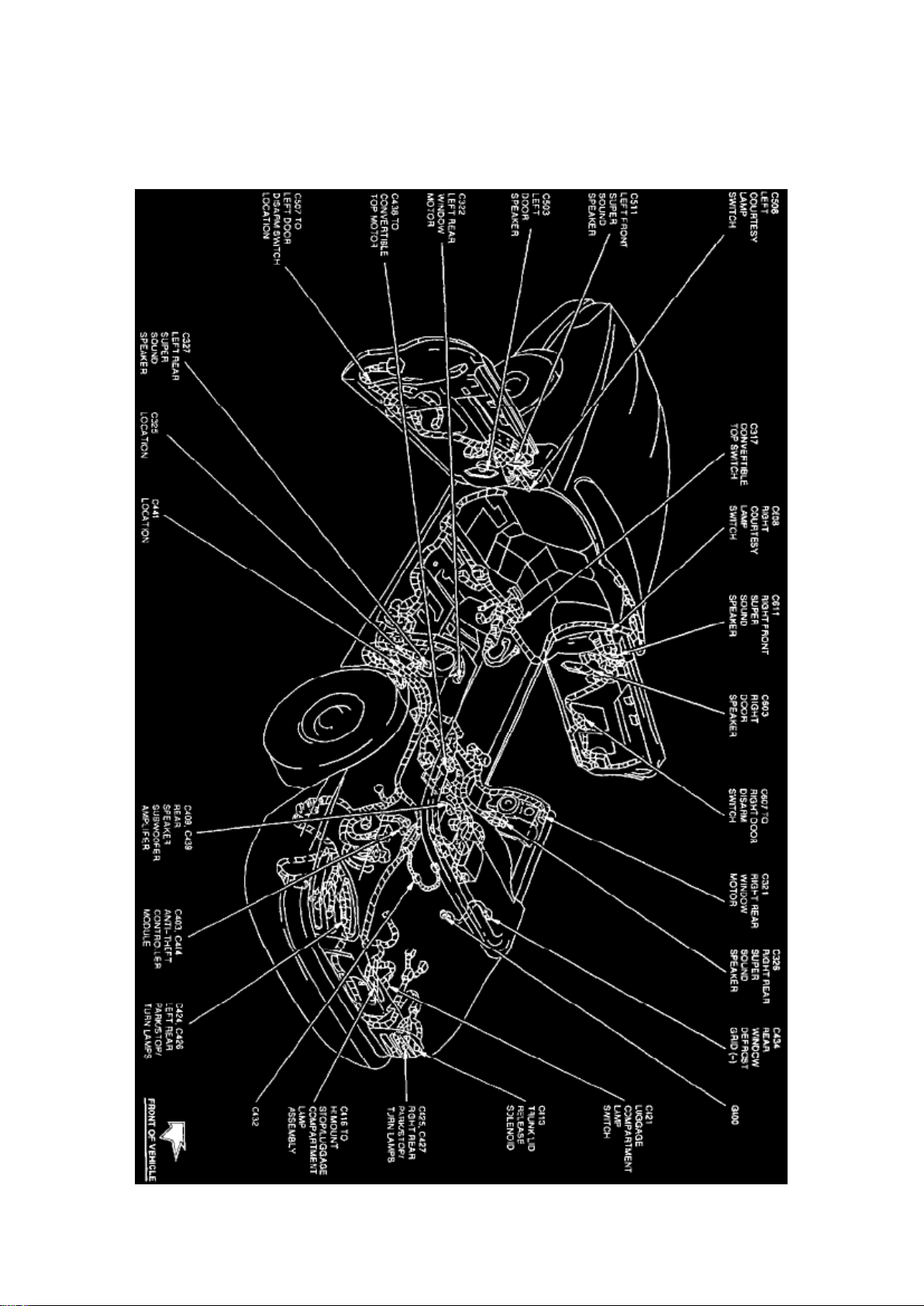
Alarm Module: Locations Anti-Theft Control Module
Convertible
Full Body View (Convertible)
The Anti-Theft Controller Module is located at the LH rear of the trunk, behind trim panel.
Coupe
Page 8
Ford Mustang Cobra Workshop Manual (V8-281 4.6L DOHC VIN V MFI (1997))
Ford Workshop Manuals > Relays and Modules > Relays and Modules - Accessories and Optional Equipment > Alarm
Module, (Vehicle Antitheft) > Component Information > Locations > Anti-Theft Control Module > Page 11
Page 9

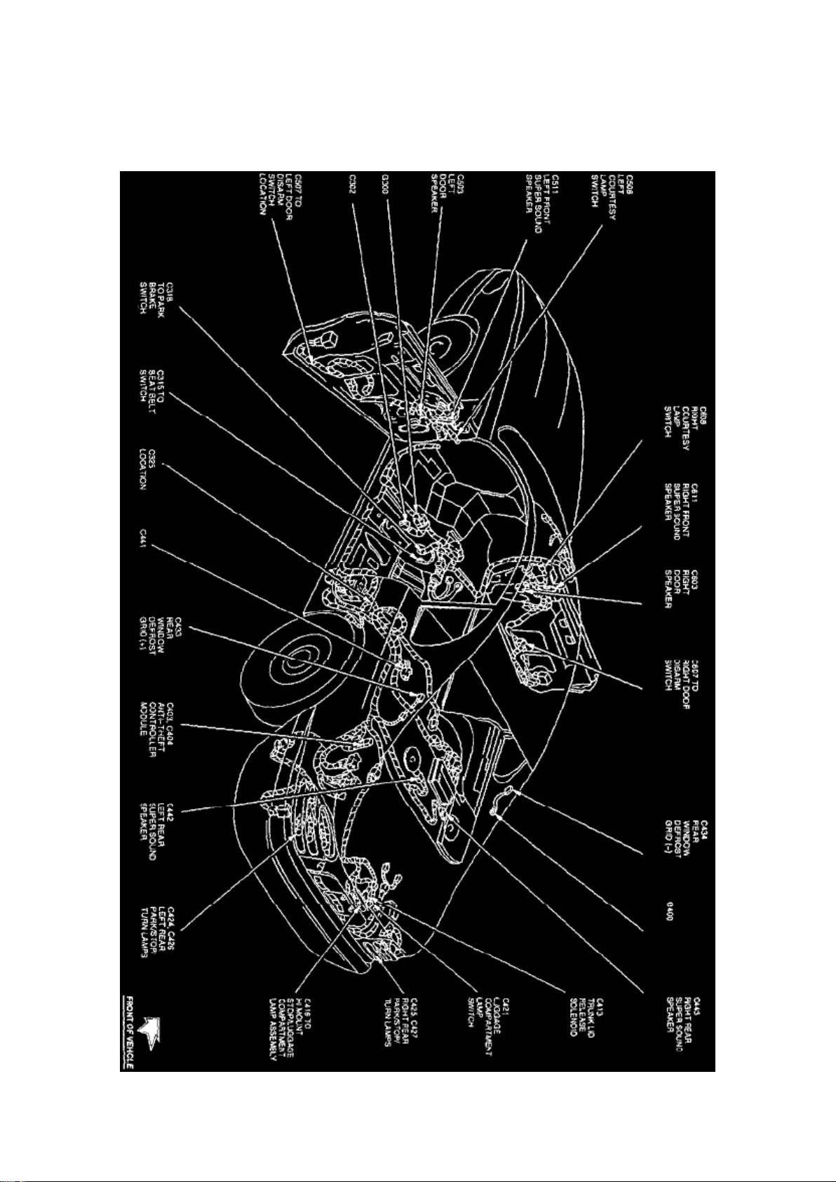
Full Body View (Coupe)
The Anti-Theft Controller Module is located at the LH rear of the trunk, behind trim panel.
Page 10
Ford Mustang Cobra Workshop Manual (V8-281 4.6L DOHC VIN V MFI (1997))
Ford Workshop Manuals > Relays and Modules > Relays and Modules - Accessories and Optional Equipment > Alarm
Module, (Vehicle Antitheft) > Component Information > Locations > Anti-Theft Control Module > Page 12
Page 11

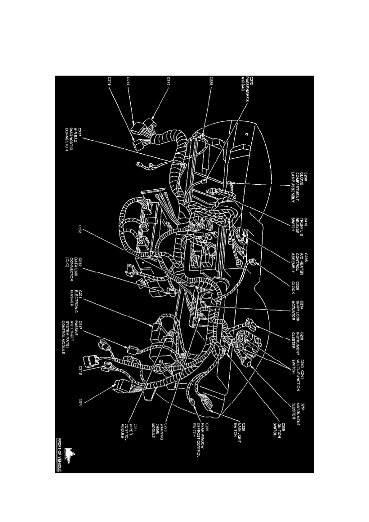
Alarm Module: Locations Passive Anti-Theft System Module
Instrument Panel View
The Passive Anti-Theft System Module is located in instrument panel near wiper control module.
Page 12
Ford Mustang Cobra Workshop Manual (V8-281 4.6L DOHC VIN V MFI (1997))
Ford Workshop Manuals > Relays and Modules > Relays and Modules - Accessories and Optional Equipment > Alarm
Module, (Vehicle Antitheft) > Component Information > Diagrams > Anti-Theft Controller Module
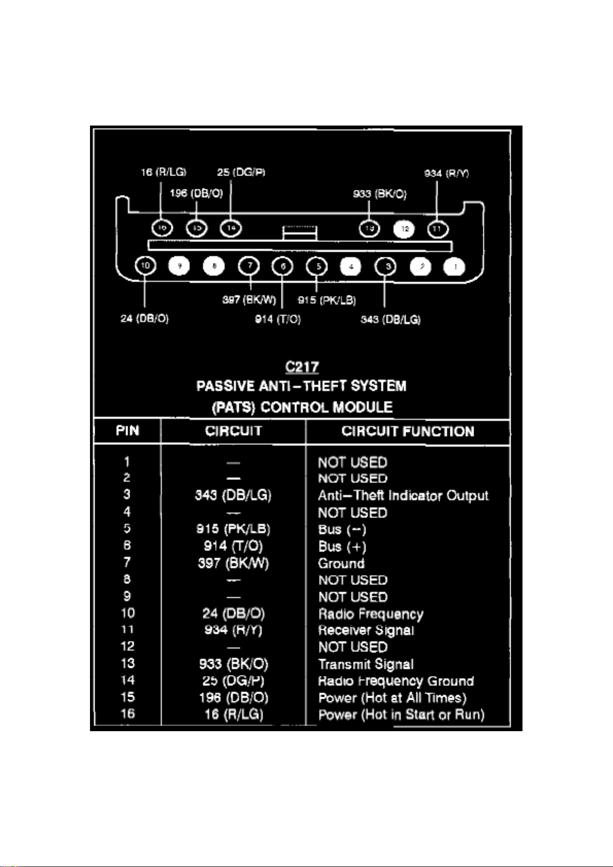
Alarm Module: Diagrams Anti-Theft Controller Module
Page 13

Passive Anti-Theft System Control Module
Page 14
Ford Mustang Cobra Workshop Manual (V8-281 4.6L DOHC VIN V MFI (1997))
Ford Workshop Manuals > Relays and Modules > Relays and Modules - Accessories and Optional Equipment > Alarm
Module, (Vehicle Antitheft) > Component Information > Diagrams > Anti-Theft Controller Module > Page 15
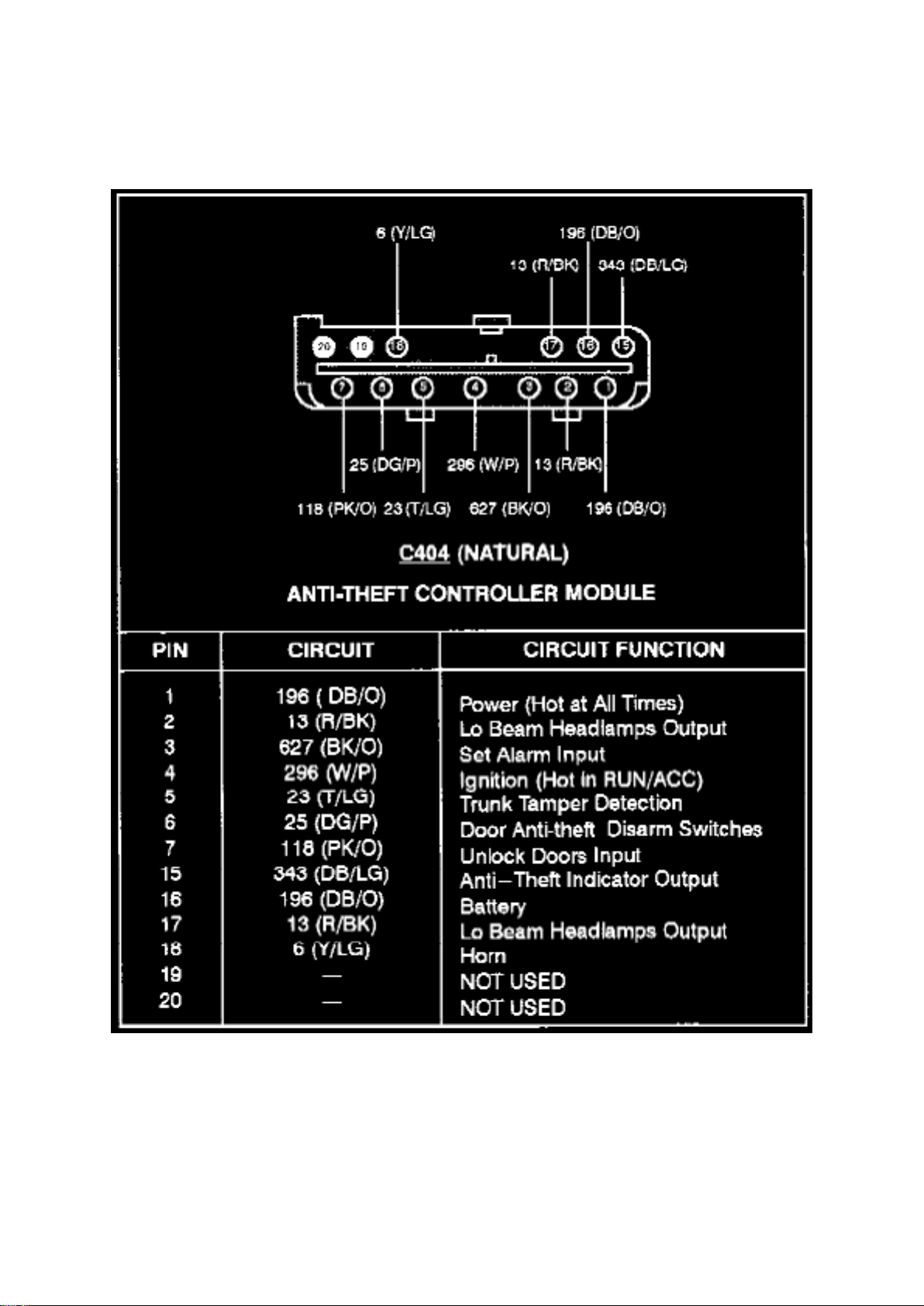
Anti-Theft Controller Module (C404)
Page 15
Ford Mustang Cobra Workshop Manual (V8-281 4.6L DOHC VIN V MFI (1997))
Ford Workshop Manuals > Relays and Modules > Relays and Modules - Accessories and Optional Equipment > Alarm
Module, (Vehicle Antitheft) > Component Information > Diagrams > Anti-Theft Controller Module > Page 16
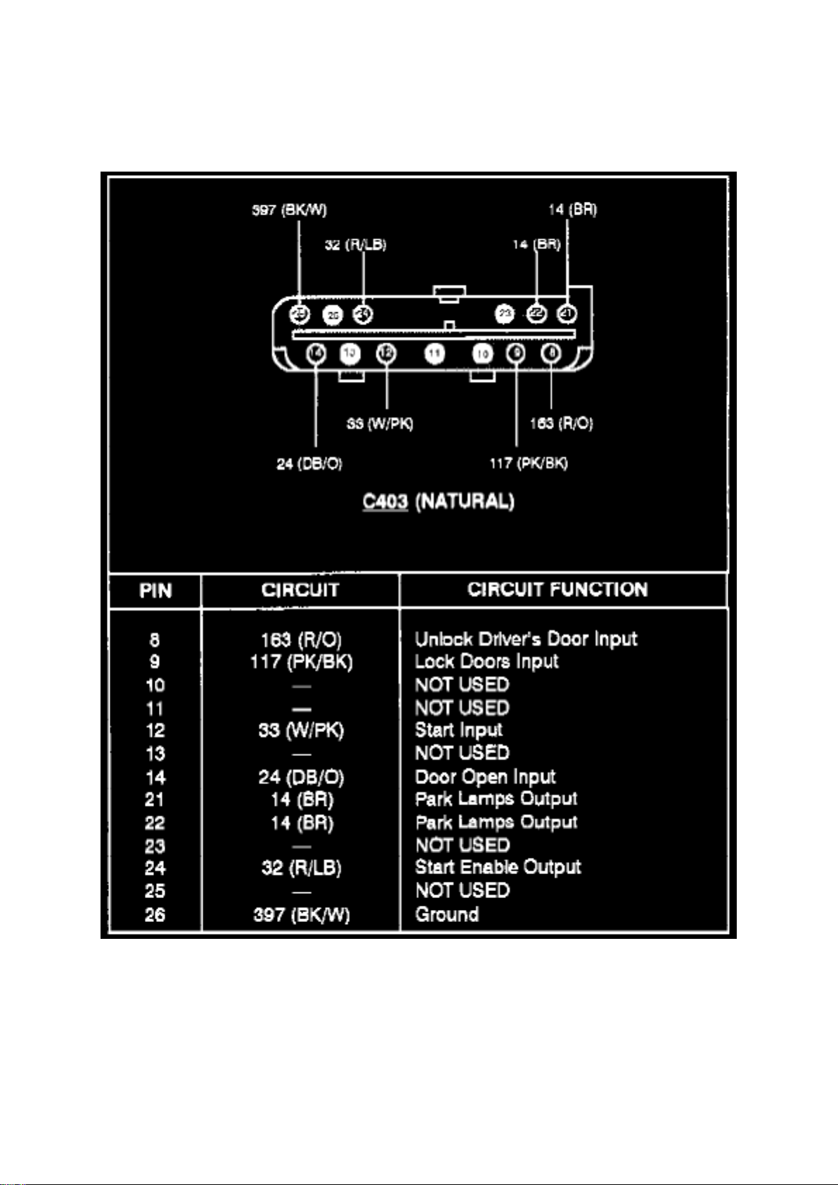
Anti-Theft Controller Module (C403)
Page 16
Ford Mustang Cobra Workshop Manual (V8-281 4.6L DOHC VIN V MFI (1997))
Ford Workshop Manuals > Relays and Modules > Relays and Modules - Accessories and Optional Equipment > Alarm
Module, (Vehicle Antitheft) > Component Information > Diagrams > Anti-Theft Controller Module > Page 17
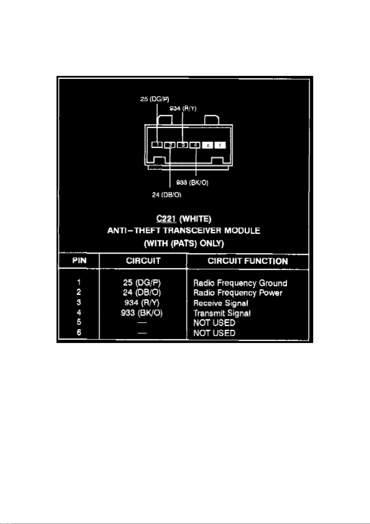
Anti-Theft Transceiver Module (With Passive Anti-Theft System Only)
Page 17

Ford Mustang Cobra Workshop Manual (V8-281 4.6L DOHC VIN V MFI (1997))
Ford Workshop Manuals > Relays and Modules > Relays and Modules - Accessories and Optional Equipment > Alarm
Module, (Vehicle Antitheft) > Component Information > Service and Repair > Key Initialization
Page 18

Alarm Module: Service and Repair Key Initialization
Key Initialization
The system provides a key initialization procedure in the event all keys programmed into the
system have been lost, or only one key was lost and the customer wants to make sure the lost key
will no longer start his vehicle.
The vehicle protection system also allows for the reprogramming of the system if the ignition lock
assembly requires replacement. This mode requires only one encoded key be programmed before
the passive anti-theft system module will send the vehicle enable message to the Powertrain
Control Module (PCM).
To erase all keys in memory and store an unprogrammed key in memory, See: Spare Key
Programming
- If a programmed encoded ignition key is available:
(1) Place key in ignition switch and turn to RUN position. (2) Enter NGS: PATS, ACTIVE
COMMAND modes. (3) Select ignition key code ERASE ON (within 5 seconds, all key codes
stored will be erased). (4) Turn ignition switch to OFF and then back to RUN position to program
the first key into memory. (5) Follow spare key programming procedure as described for
programming in any additional keys required.
- If no programmed keys are available follow the procedure outlined above; however, instead of
taking 5 seconds to complete key erasing, it will take a minimum of 8 minutes.
An alternate programming method is possible and is intended to keep a customer from being
stranded, and who has no access to a service facility equipped with diagnostic tools. This
interactive procedure takes approximately 45 minutes to maintain the high level of theft protection
provided by the system. When initializing the system using this procedure, it must be followed
precisely or the system will abort and the procedure will need to be started over.
The alternate programming method operates as follows:
- Insert an unprogrammed encoded key into the ignition lock and turn ignition switch to RUN. The
THEFT Indicator will begin flashing.
- Follow this procedure three times: After 15 minutes of flashing, the THEFT indicator will
extinguish. Within five minutes after the THEFT indicator has gone out, turn the ignition switch once
to OFF for a second, then back to RUN. The THEFT indicator will resume flashing for another 15
minutes.
- After the third time (at 45 minutes from start), the control module will erase all stored keys and
memorize the unprogrammed key as valid. This key will now start the vehicle. Additional keys can
be programmed using the Spare Key Programming procedure.
Page 19
Ford Mustang Cobra Workshop Manual (V8-281 4.6L DOHC VIN V MFI (1997))
Ford Workshop Manuals > Relays and Modules > Relays and Modules - Accessories and Optional Equipment > Alarm
Module, (Vehicle Antitheft) > Component Information > Service and Repair > Key Initialization > Page 20
Alarm Module: Service and Repair Removal and Installation
Anti-Theft System, Active
REMOVAL AND INSTALLATION
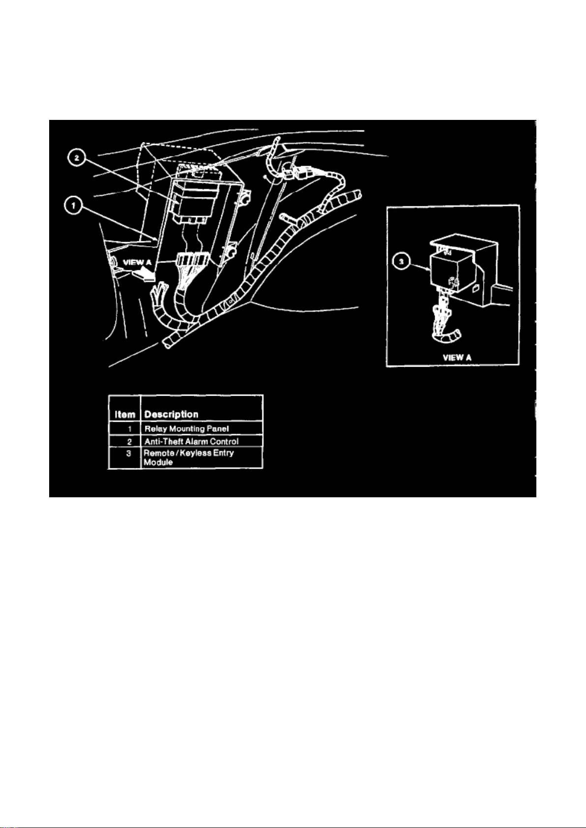
1. Disconnect battery ground cable. 2. Open the luggage compartment door. Remove trim from LH
side of luggage compartment. 3. Disconnect electrical connectors from anti-theft alarm control. 4.
Remove anti-theft alarm control by pushing on the panel retaining tab below the anti-theft alarm
control while sliding the anti-theft alarm control
down.
INSTALLATION
1. Follow removal procedure in reverse order. 2. Test system for proper operation.
Anti-Theft System, Passive
Page 20
Ford Mustang Cobra Workshop Manual (V8-281 4.6L DOHC VIN V MFI (1997))
Ford Workshop Manuals > Relays and Modules > Relays and Modules - Accessories and Optional Equipment > Alarm
Module, (Vehicle Antitheft) > Component Information > Service and Repair > Key Initialization > Page 21
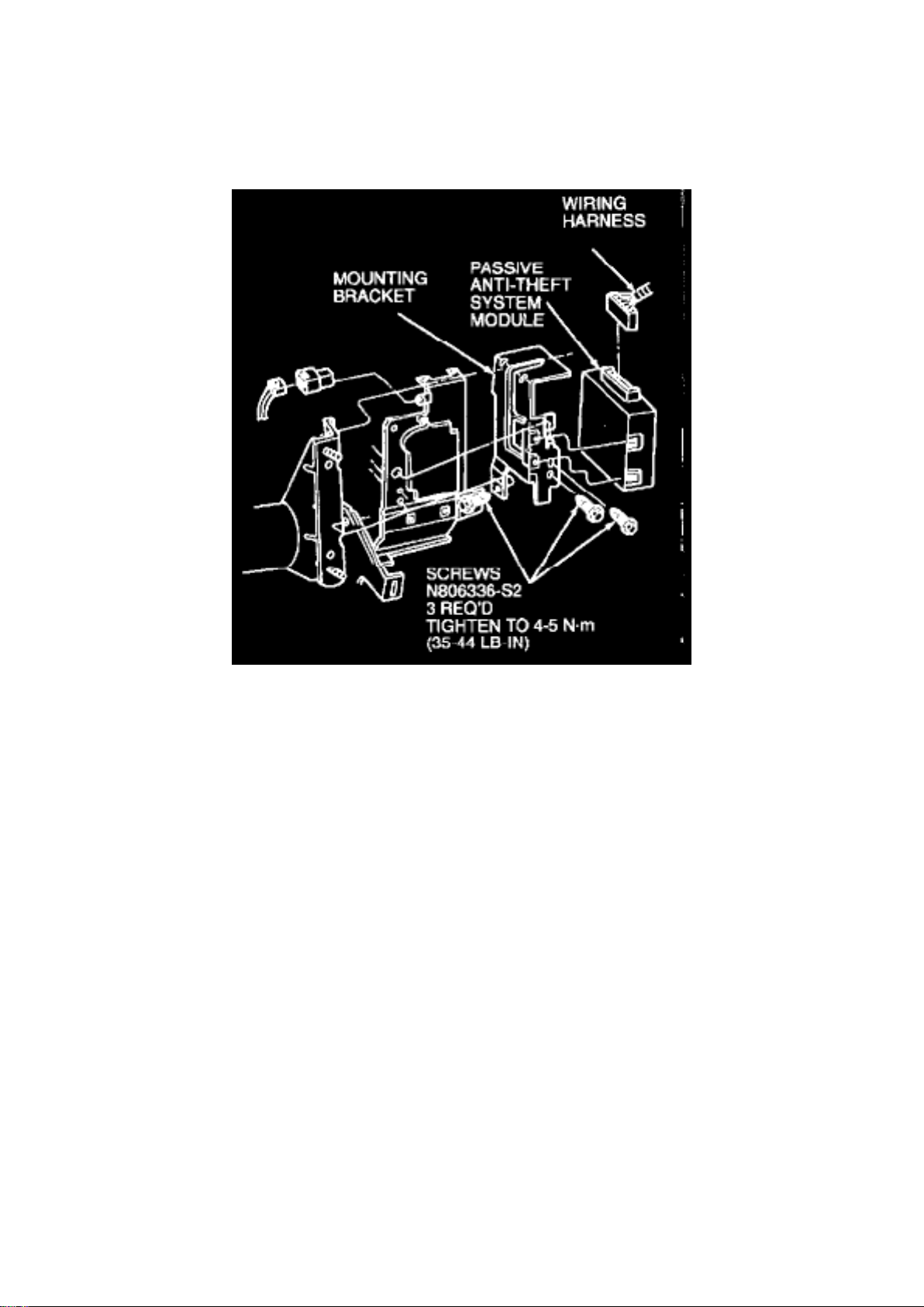
REMOVAL
1. Disconnect battery ground cable. 2. Remove driver side knee bolster to access passive anti-theft
system module located to right of fuse junction panel. 3. Remove three fasteners retaining module
and bracket and one fastener attaching metal brace near module. 4. Disconnect main wiring
harness connector and remove passive anti-theft system module and mounting bracket.
INSTALLATION
1. Follow removal procedure in reverse order. 2. Tighten all three screws to 4-5 N.m (35-44 lb-in).
Page 21

Ford Mustang Cobra Workshop Manual (V8-281 4.6L DOHC VIN V MFI (1997))
Ford Workshop Manuals > Relays and Modules > Relays and Modules - Accessories and Optional Equipment > Alarm
Module, (Vehicle Antitheft) > Component Information > Service and Repair > Key Initialization > Page 22
Page 22

Alarm Module: Service and Repair Spare Key Programming
Spare Key Programming
NOTE: Service control modules require only one key to be programmed before allowing the vehicle
to start. If a control module is changed, the technician must inform the customer to program any
additional keys using the Spare Key Programming procedure detailed in the Owner Guide.
The system has capacity to store a maximum of 16 keys. After the initial key has been
programmed or using any programmed key, follow the steps below:
NOTE: Encoded keys must have correct mechanical key cut for vehicle.
- Cycle ignition switch from RUN to OFF with a programmed key.
- Within 15 seconds after this cycle, insert a new encoded key into ignition switch and turn to RUN
or START
- If programming is successful, the THEFT indicator will illuminate for two seconds and the control
module will enable the vehicle to start.
- Repeat until all chosen keys have been programmed. up to 16 keys total.
- If programming is not successful, the THEFT indicator will:
- Flash for one minute if no key code is received. The key is either damaged or is a non-encoded
key. (Try a new key and start procedure over again.)
- Flash for 15 minutes if key code is received yet engine is dis abled. The key was not programmed
successfully. Start procedure over again.
- If programming is not successful, possibly the new key was not inserted within 15 seconds, all 16
key codes have been stored, or the key is a non-encoded key. If the key was not encoded or
inserted within 15 seconds, repeat procedure.
Page 23
Ford Mustang Cobra Workshop Manual (V8-281 4.6L DOHC VIN V MFI (1997))
Ford Workshop Manuals > Relays and Modules > Relays and Modules - Accessories and Optional Equipment > Keyless
Entry Module > Component Information > Locations > Convertible
Page 24

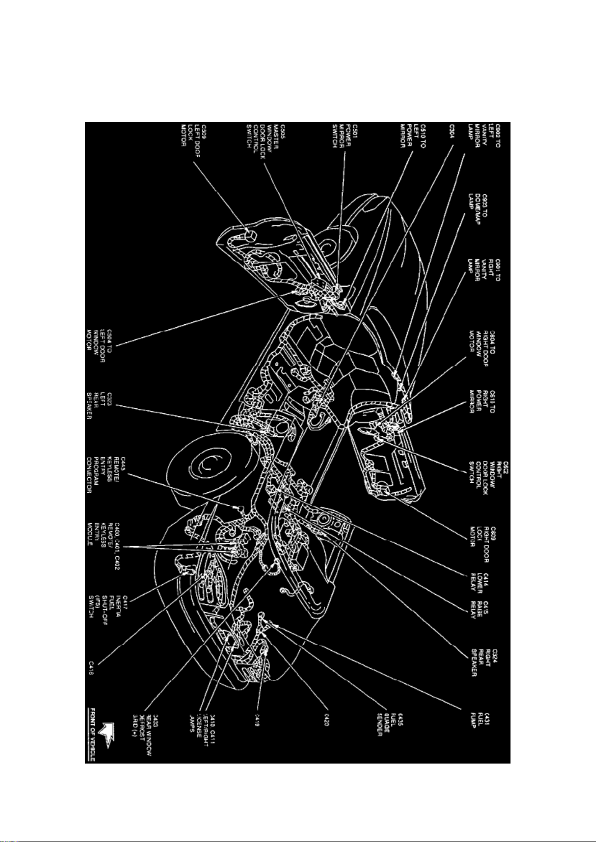
Keyless Entry Module: Locations Convertible
Full Body View (Convertible)
The Remote/Keyless Entry Module is located at the LH rear of trunk, behind side trim.
Page 25
Ford Mustang Cobra Workshop Manual (V8-281 4.6L DOHC VIN V MFI (1997))
Ford Workshop Manuals > Relays and Modules > Relays and Modules - Accessories and Optional Equipment > Keyless
Entry Module > Component Information > Locations > Convertible > Page 27
Page 26

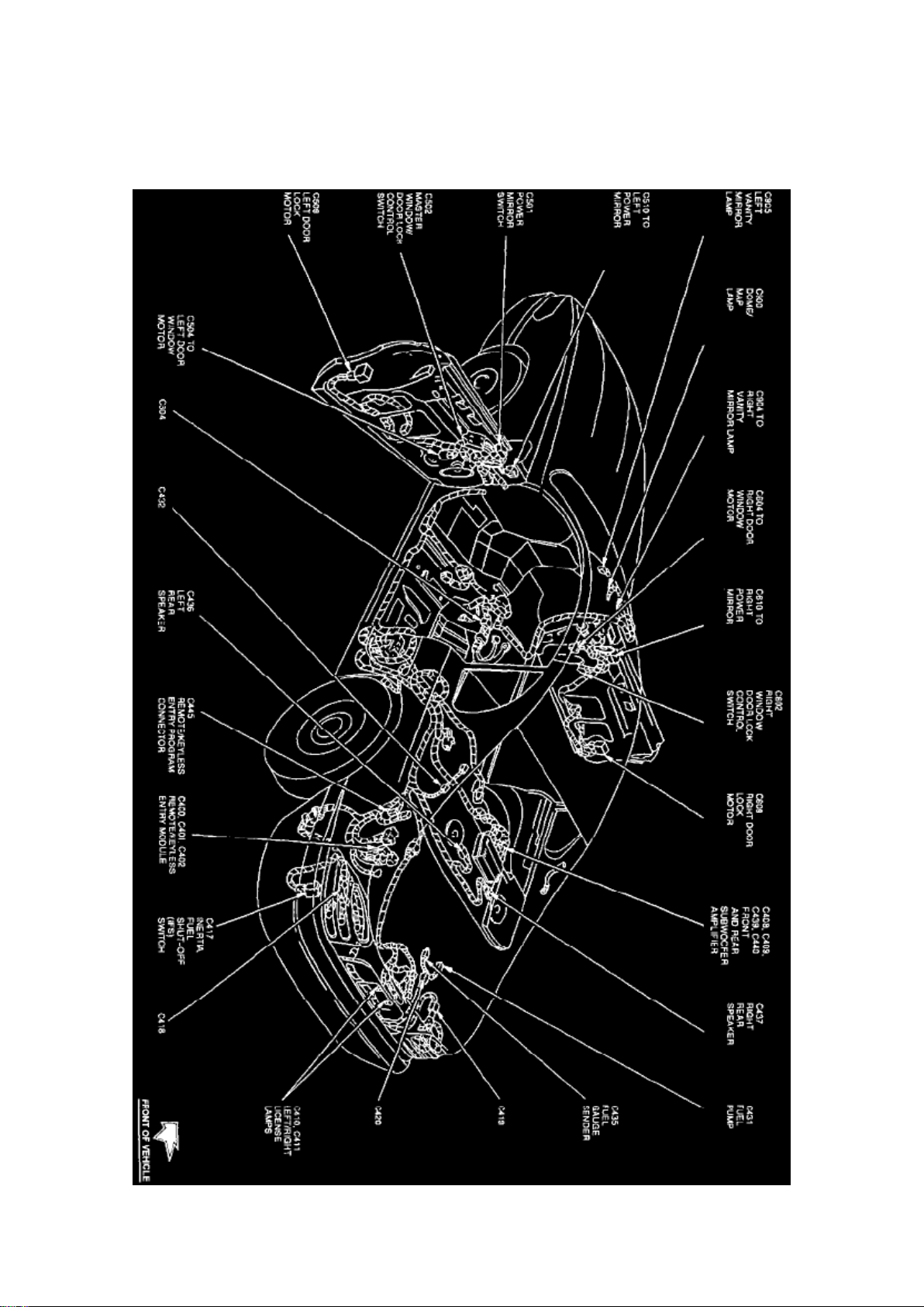
Keyless Entry Module: Locations Coupe
Full Body View (Coupe)
The Remote/Keyless Entry Module is located at the LH rear of trunk, behind side trim.
Page 27
Ford Mustang Cobra Workshop Manual (V8-281 4.6L DOHC VIN V MFI (1997))
Ford Workshop Manuals > Relays and Modules > Relays and Modules - Accessories and Optional Equipment > Keyless
Entry Module > Component Information > Locations > Page 28
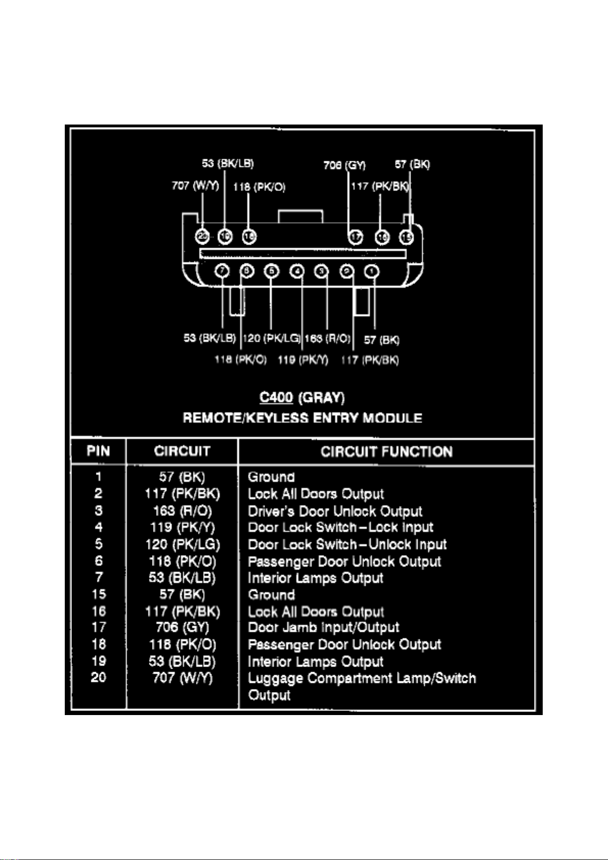
Keyless Entry Module: Diagrams
Remote/Keyless Entry Module (C400)
Page 28
Ford Mustang Cobra Workshop Manual (V8-281 4.6L DOHC VIN V MFI (1997))
Ford Workshop Manuals > Relays and Modules > Relays and Modules - Accessories and Optional Equipment > Keyless
Entry Module > Component Information > Locations > Page 29
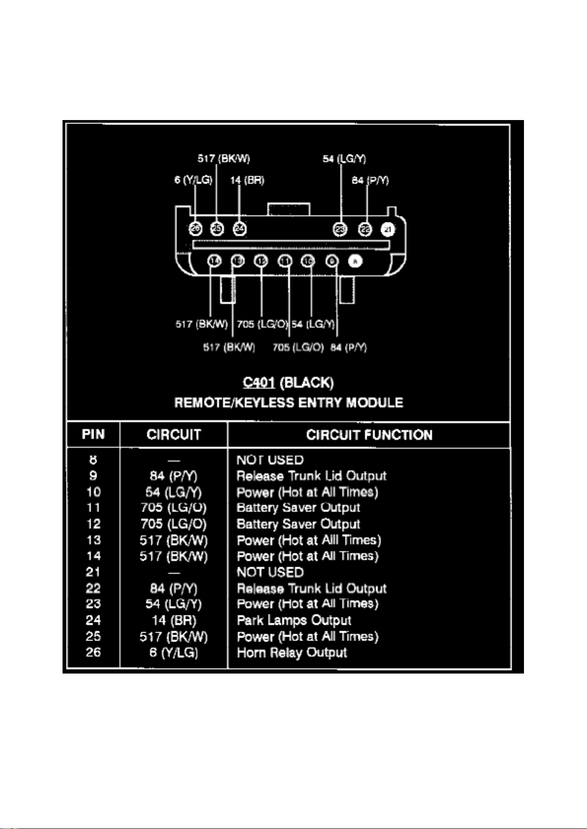
Remote/Keyless Entry Module (C401)
Page 29
Ford Mustang Cobra Workshop Manual (V8-281 4.6L DOHC VIN V MFI (1997))
Ford Workshop Manuals > Relays and Modules > Relays and Modules - Accessories and Optional Equipment > Keyless
Entry Module > Component Information > Locations > Page 30
Page 30

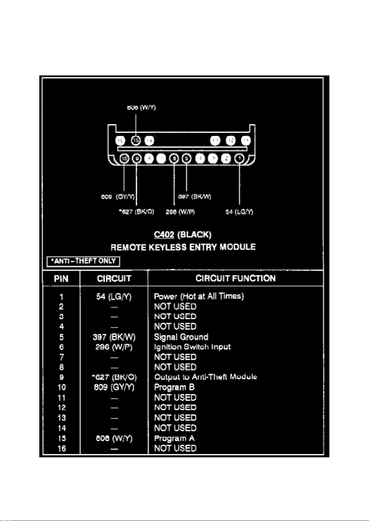
Remote/Keyless Entry Module (C402)
Page 31

Ford Mustang Cobra Workshop Manual (V8-281 4.6L DOHC VIN V MFI (1997))
Ford Workshop Manuals > Relays and Modules > Relays and Modules - Accessories and Optional Equipment > Keyless
Entry Module > Component Information > Description and Operation > Battery Saver
Page 32

Keyless Entry Module: Description and Operation Battery Saver
NOTE: The battery saver relay does NOT control power to the headlamps.
The remote keyless entry module includes a battery saver relay which supplies power to:
^ Convenience lamps (Circuit 705, LG/O).
^ Interior lamp (Circuit 53, BK/LB)
^ Luggage compartment lamp (Circuit 707, W/Y) when active. When the battery saver relay
deactivates, power is removed from these lamps.
The battery saver relay:
^ Activates any time the remote keyless entry module receives an input signal.
^ Deactivates 45 minutes after the last input to the remote keyless entry module.
Page 33

Ford Mustang Cobra Workshop Manual (V8-281 4.6L DOHC VIN V MFI (1997))
Ford Workshop Manuals > Relays and Modules > Relays and Modules - Accessories and Optional Equipment > Keyless
Entry Module > Component Information > Description and Operation > Battery Saver > Page 33
Page 34

Keyless Entry Module: Description and Operation Module, Keyless Entry Remote
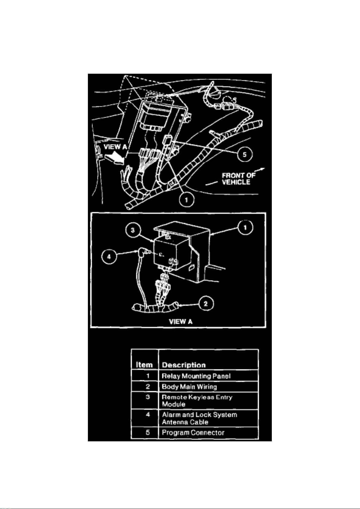
^ The remote keyless entry module is located behind the LH luggage compartment trim panel.
^ It contains a radio receiver that receives a signal from the keyless entry remote transmitter
through the remote keyless entry module antenna.
^ It sends the appropriate command to the power door locks, the horn relay, the park lamps, and
the anti-theft warning system if equipped.
^ The remote keyless entry module is equipped with battery backup which holds the programmed
code in memory when the vehicle battery is disconnected.
Page 35
Ford Mustang Cobra Workshop Manual (V8-281 4.6L DOHC VIN V MFI (1997))
Ford Workshop Manuals > Relays and Modules > Relays and Modules - Accessories and Optional Equipment > Keyless
Entry Module > Component Information > Description and Operation > Page 34
Keyless Entry Module: Service and Repair
Page 36

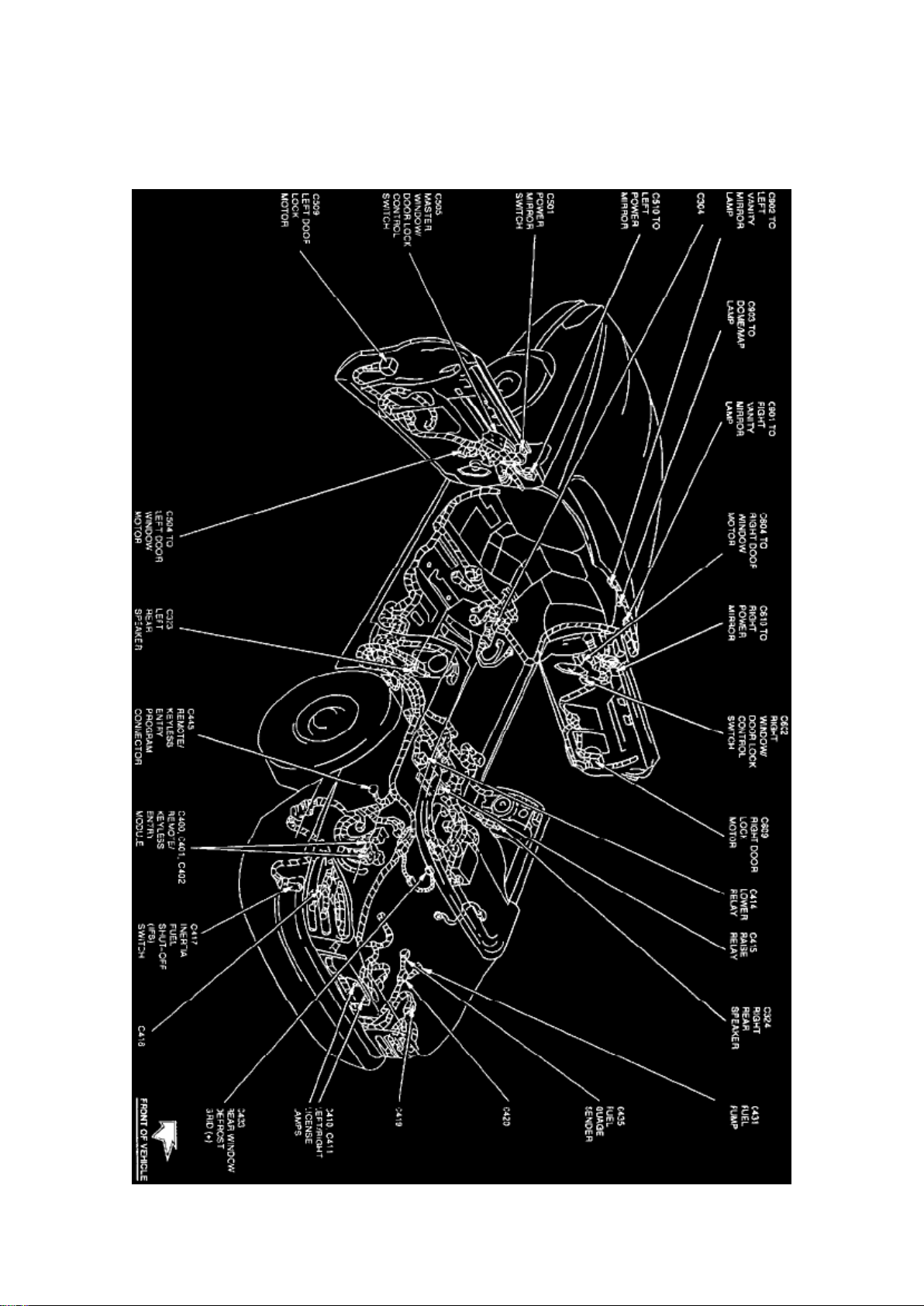
REMOVAL
1. Disconnect battery ground cable. 2. Open luggage compartment door. 3. Remove LH side
luggage compartment trim panel and locate remote keyless entry module in LH relay mounting
panel. 4. Disengage retaining tabs on relay mounting panel and lower relay mounting panel. 5.
Remove the remote keyless entry module from the relay mounting panel. 6. Disconnect three
connectors and alarm and lock system antenna connector.
INSTALLATION
1. Follow removal procedure in reverse order.
Page 37
Ford Mustang Cobra Workshop Manual (V8-281 4.6L DOHC VIN V MFI (1997))
Ford Workshop Manuals > Relays and Modules > Relays and Modules - Body and Frame > Convertible Top Relay >
Component Information > Locations > Lower Relay
Page 38

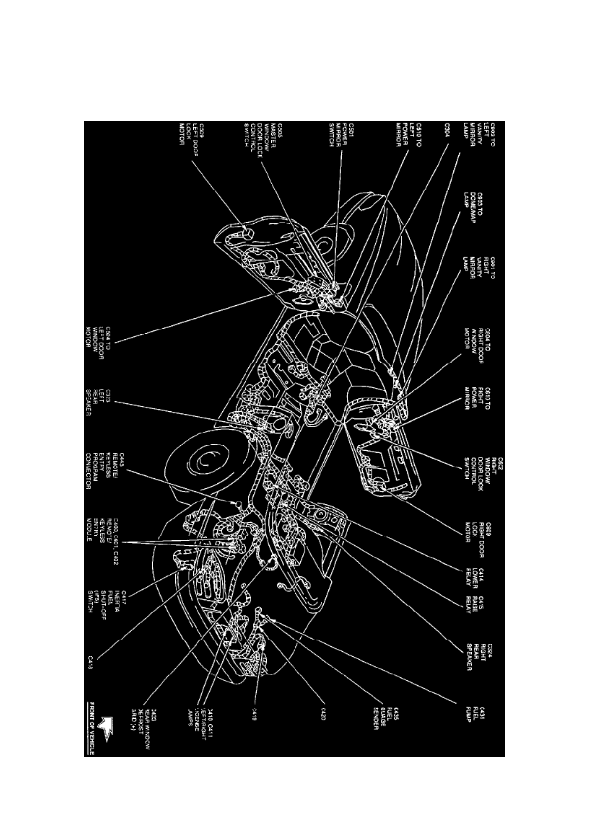
Convertible Top Relay: Locations Lower Relay
Full Body View (Convertible)
The Lower Relay is located behind rear seat, at the LH side of the convertible top motor.
Page 39
Ford Mustang Cobra Workshop Manual (V8-281 4.6L DOHC VIN V MFI (1997))
Ford Workshop Manuals > Relays and Modules > Relays and Modules - Body and Frame > Convertible Top Relay >
Component Information > Locations > Lower Relay > Page 40
Page 40

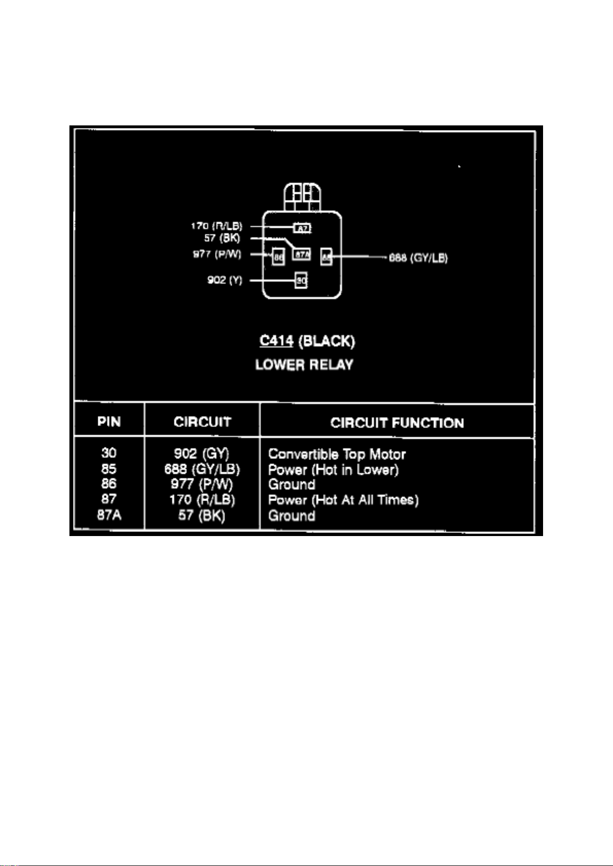
Convertible Top Relay: Locations Raise Relay
Full Body View (Convertible)
The Raise Relay is located behind top center of rear seat, at the LH side of the convertible top
motor.
Page 41
Ford Mustang Cobra Workshop Manual (V8-281 4.6L DOHC VIN V MFI (1997))
Ford Workshop Manuals > Relays and Modules > Relays and Modules - Body and Frame > Convertible Top Relay >
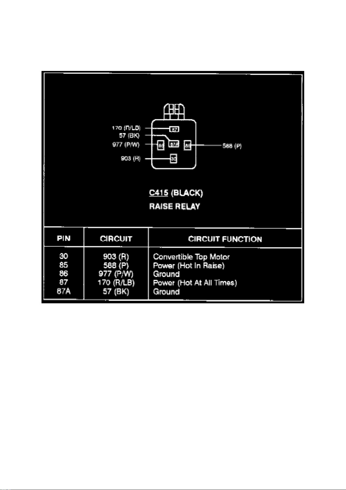
Component Information > Diagrams > Lower Relay
Lower Relay
Page 42
Ford Mustang Cobra Workshop Manual (V8-281 4.6L DOHC VIN V MFI (1997))
Ford Workshop Manuals > Relays and Modules > Relays and Modules - Body and Frame > Convertible Top Relay >
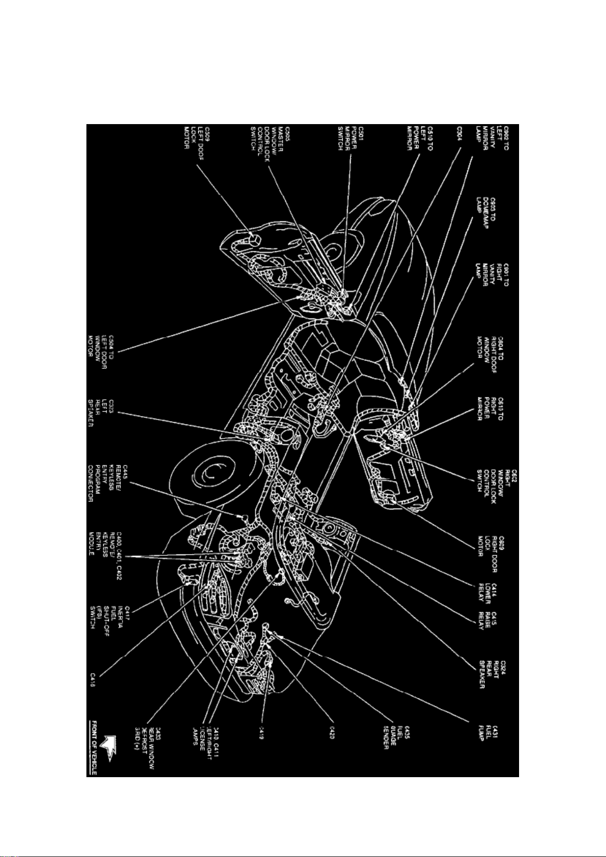
Component Information > Diagrams > Lower Relay > Page 43
Raise Relay
Page 43
Ford Mustang Cobra Workshop Manual (V8-281 4.6L DOHC VIN V MFI (1997))
Ford Workshop Manuals > Relays and Modules > Relays and Modules - Body and Frame > Keyless Entry Module >
Component Information > Locations > Convertible
Page 44

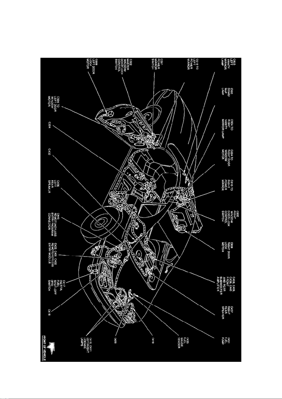
Keyless Entry Module: Locations Convertible
Full Body View (Convertible)
The Remote/Keyless Entry Module is located at the LH rear of trunk, behind side trim.
Page 45
Ford Mustang Cobra Workshop Manual (V8-281 4.6L DOHC VIN V MFI (1997))
Ford Workshop Manuals > Relays and Modules > Relays and Modules - Body and Frame > Keyless Entry Module >
Component Information > Locations > Convertible > Page 48
Page 46

Keyless Entry Module: Locations Coupe
Full Body View (Coupe)
The Remote/Keyless Entry Module is located at the LH rear of trunk, behind side trim.
Page 47
Ford Mustang Cobra Workshop Manual (V8-281 4.6L DOHC VIN V MFI (1997))
Ford Workshop Manuals > Relays and Modules > Relays and Modules - Body and Frame > Keyless Entry Module >
Component Information > Locations > Page 49
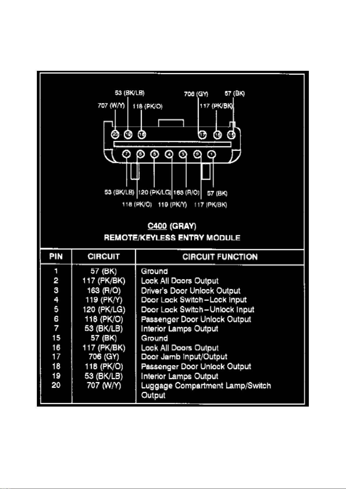
Keyless Entry Module: Diagrams
Remote/Keyless Entry Module (C400)
Page 48
Ford Mustang Cobra Workshop Manual (V8-281 4.6L DOHC VIN V MFI (1997))
Ford Workshop Manuals > Relays and Modules > Relays and Modules - Body and Frame > Keyless Entry Module >
Component Information > Locations > Page 50
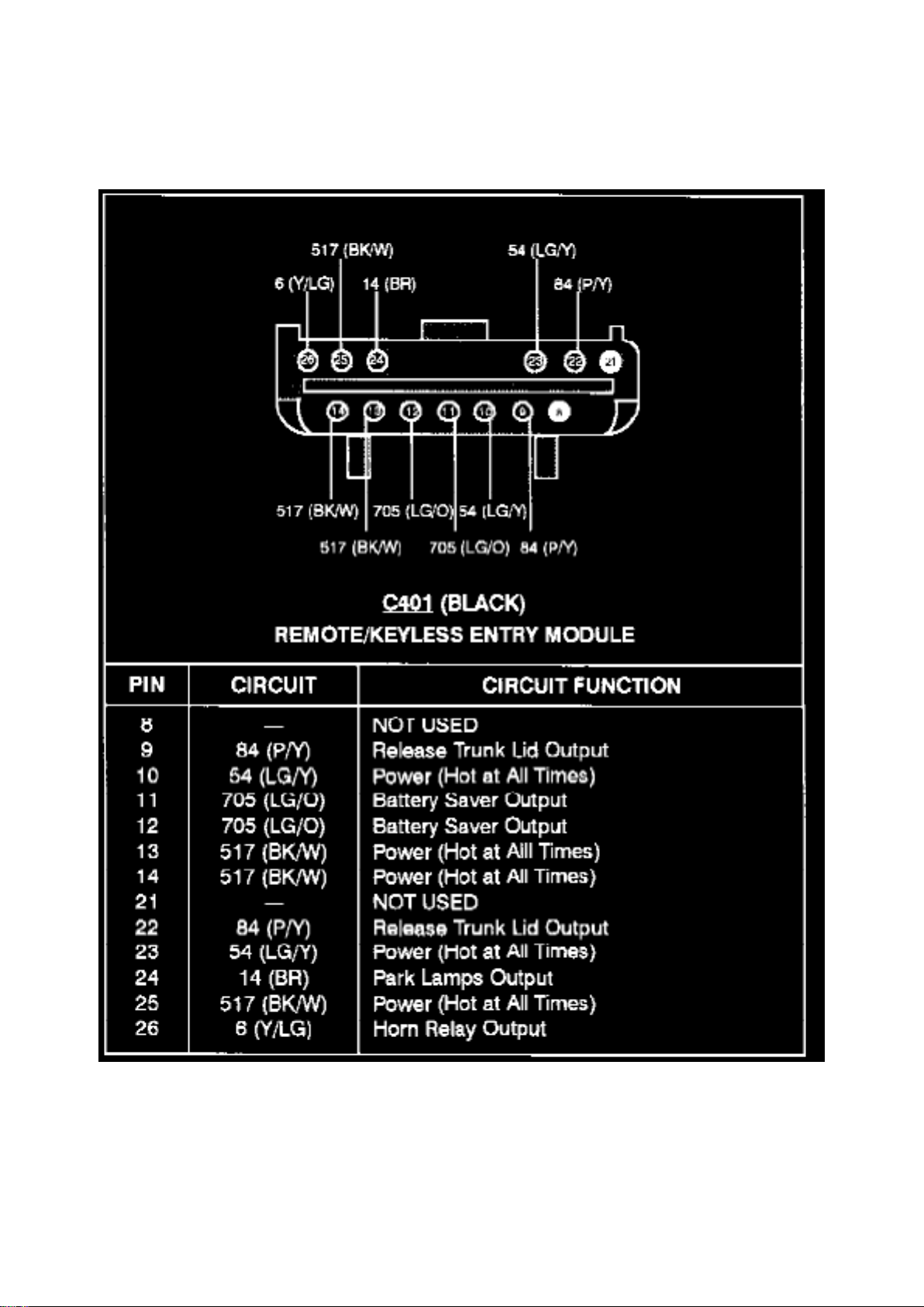
Remote/Keyless Entry Module (C401)
Page 49
Ford Mustang Cobra Workshop Manual (V8-281 4.6L DOHC VIN V MFI (1997))
Ford Workshop Manuals > Relays and Modules > Relays and Modules - Body and Frame > Keyless Entry Module >
Component Information > Locations > Page 51
Page 50

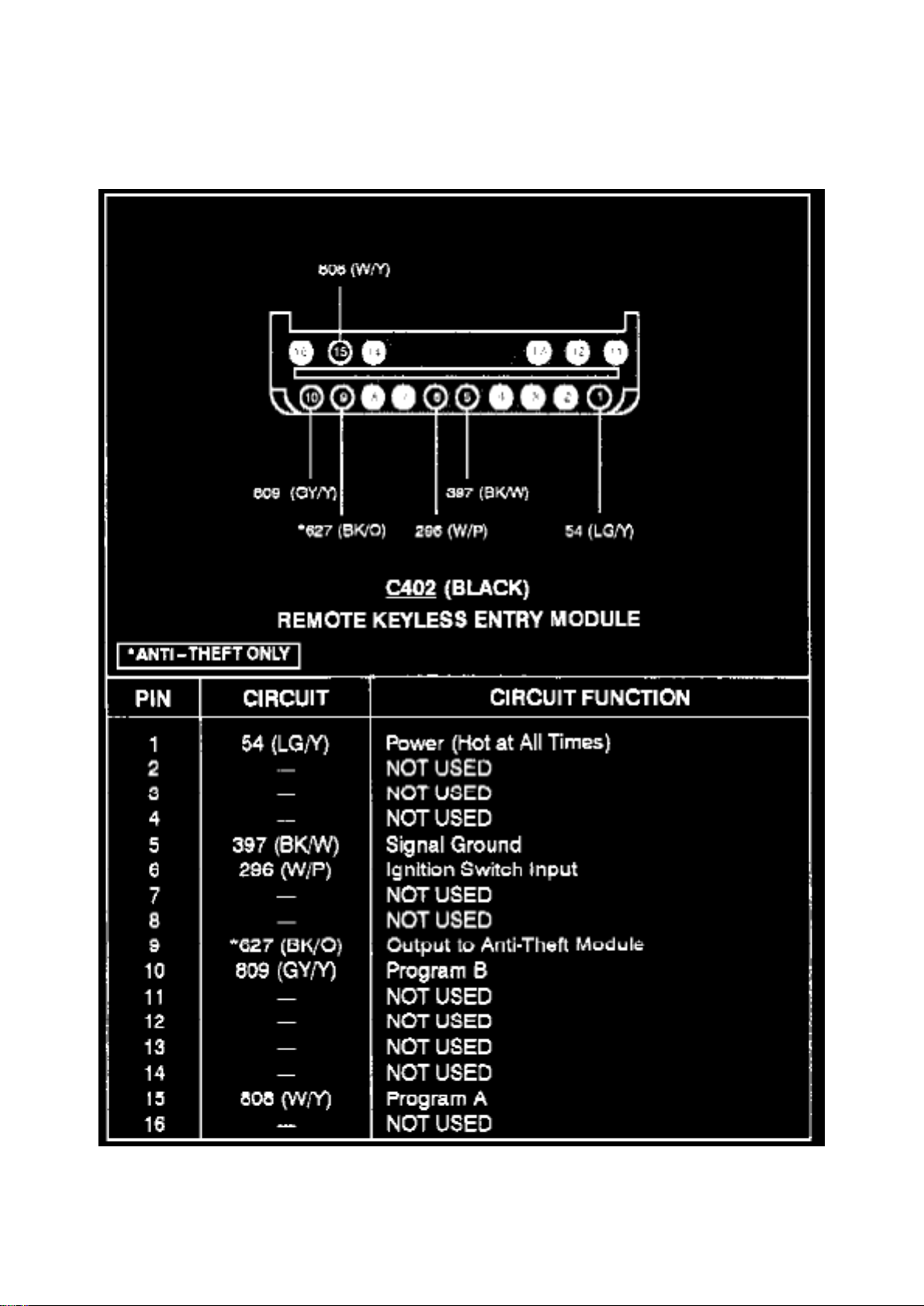
Remote/Keyless Entry Module (C402)
Page 51

Ford Mustang Cobra Workshop Manual (V8-281 4.6L DOHC VIN V MFI (1997))
Ford Workshop Manuals > Relays and Modules > Relays and Modules - Body and Frame > Keyless Entry Module >
Component Information > Description and Operation > Battery Saver
Page 52

Keyless Entry Module: Description and Operation Battery Saver
NOTE: The battery saver relay does NOT control power to the headlamps.
The remote keyless entry module includes a battery saver relay which supplies power to:
^ Convenience lamps (Circuit 705, LG/O).
^ Interior lamp (Circuit 53, BK/LB)
^ Luggage compartment lamp (Circuit 707, W/Y) when active. When the battery saver relay
deactivates, power is removed from these lamps.
The battery saver relay:
^ Activates any time the remote keyless entry module receives an input signal.
^ Deactivates 45 minutes after the last input to the remote keyless entry module.
Page 53

Ford Mustang Cobra Workshop Manual (V8-281 4.6L DOHC VIN V MFI (1997))
Ford Workshop Manuals > Relays and Modules > Relays and Modules - Body and Frame > Keyless Entry Module >
Component Information > Description and Operation > Battery Saver > Page 54
Page 54

Keyless Entry Module: Description and Operation Module, Keyless Entry Remote
^ The remote keyless entry module is located behind the LH luggage compartment trim panel.
^ It contains a radio receiver that receives a signal from the keyless entry remote transmitter
through the remote keyless entry module antenna.
^ It sends the appropriate command to the power door locks, the horn relay, the park lamps, and
the anti-theft warning system if equipped.
^ The remote keyless entry module is equipped with battery backup which holds the programmed
code in memory when the vehicle battery is disconnected.
Page 55
Ford Mustang Cobra Workshop Manual (V8-281 4.6L DOHC VIN V MFI (1997))
Ford Workshop Manuals > Relays and Modules > Relays and Modules - Body and Frame > Keyless Entry Module >
Component Information > Description and Operation > Page 55
Keyless Entry Module: Service and Repair
Page 56

REMOVAL
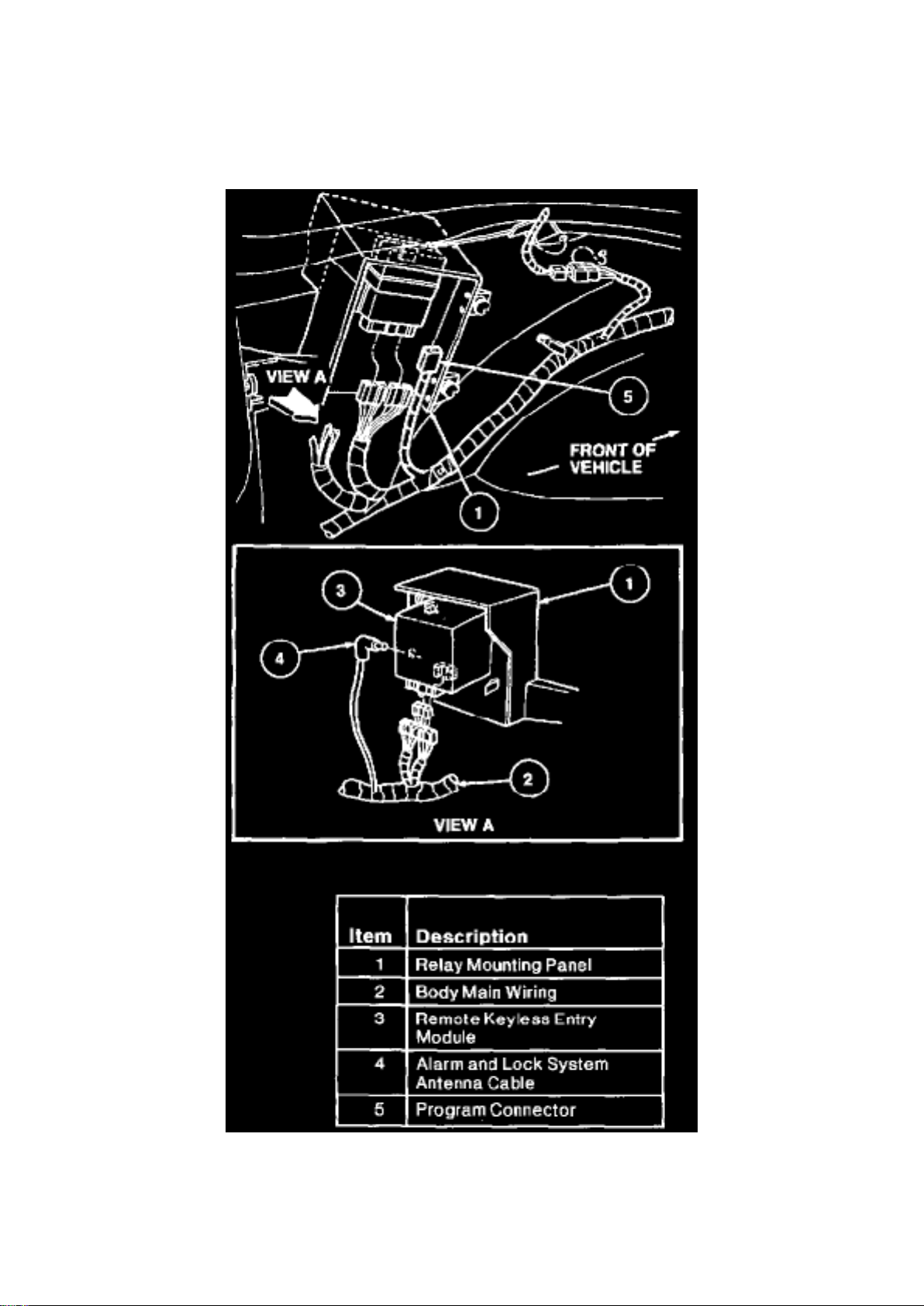
1. Disconnect battery ground cable. 2. Open luggage compartment door. 3. Remove LH side
luggage compartment trim panel and locate remote keyless entry module in LH relay mounting
panel. 4. Disengage retaining tabs on relay mounting panel and lower relay mounting panel. 5.
Remove the remote keyless entry module from the relay mounting panel. 6. Disconnect three
connectors and alarm and lock system antenna connector.
INSTALLATION
1. Follow removal procedure in reverse order.
Page 57
Ford Mustang Cobra Workshop Manual (V8-281 4.6L DOHC VIN V MFI (1997))
Ford Workshop Manuals > Relays and Modules > Relays and Modules - Brakes and Traction Control > Electronic Brake
Control Module > Component Information > Locations
Page 58

Electronic Brake Control Module: Locations
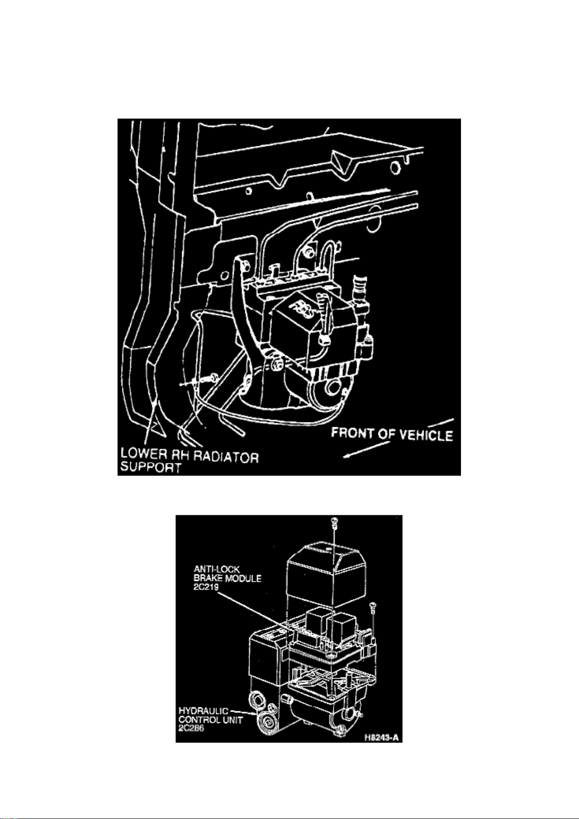
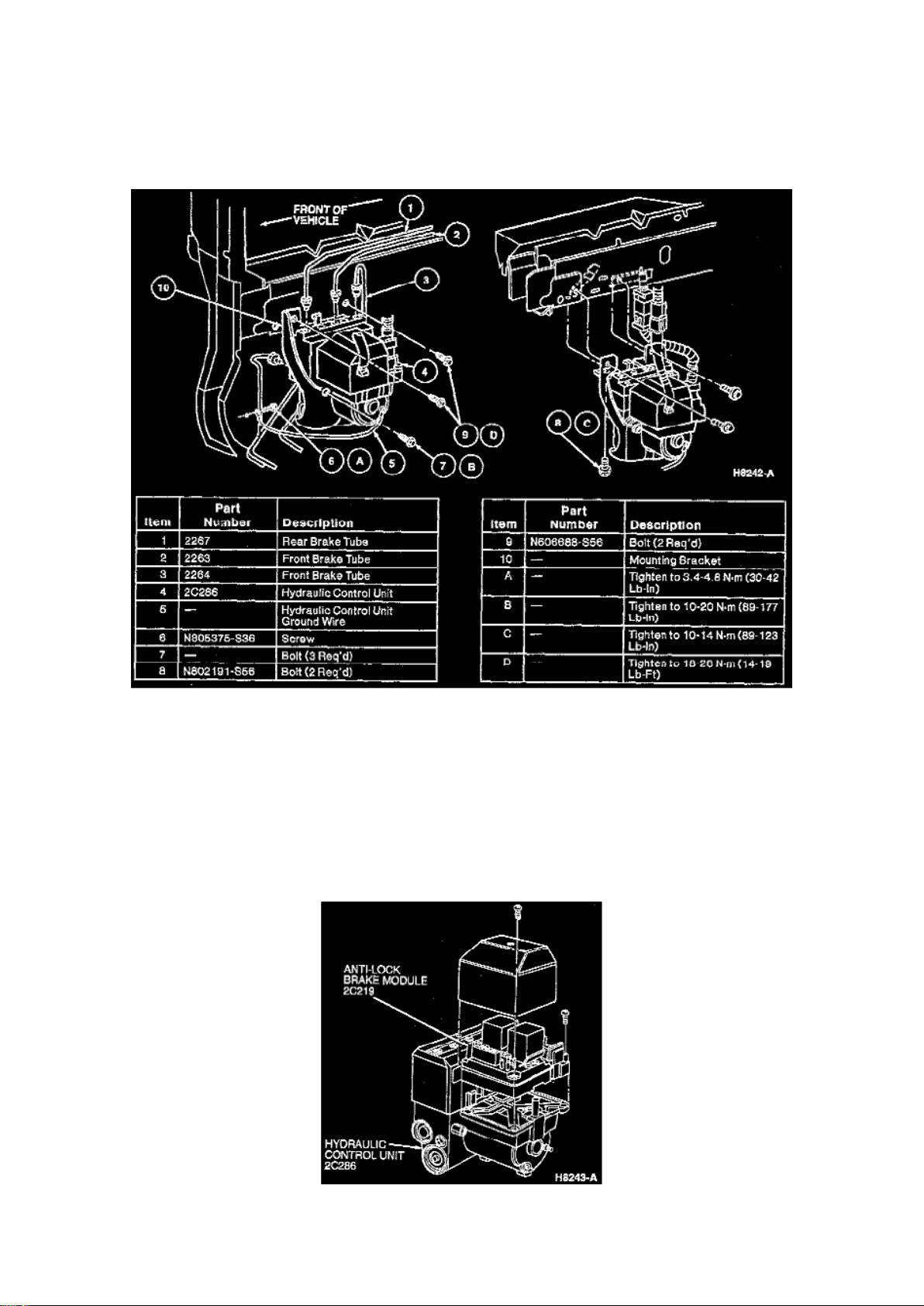
Fig. 1 ABS Hydraulic Control Unit & Anti-Lock Brake Control Module
Anti-Lock Brake Control Module/Hydraulic Control Unit
The ABS hydraulic control unit and anti-lock brake control module are assembled as a single unit.
The assembly is located in the RH lower front corner of the engine compartment, next to the
bottom of the radiator coolant recovery reservoir. The unit is mounted inside a bracket, which is
affixed to the RH frame rail.
Page 59
Ford Mustang Cobra Workshop Manual (V8-281 4.6L DOHC VIN V MFI (1997))
Ford Workshop Manuals > Relays and Modules > Relays and Modules - Brakes and Traction Control > Electronic Brake
Control Module > Component Information > Locations > Page 60
Page 60

Electronic Brake Control Module: Diagrams
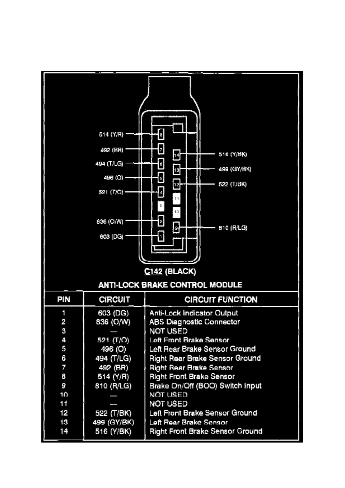
Anti-Lock Brake Control Module (C142)
Page 61
Ford Mustang Cobra Workshop Manual (V8-281 4.6L DOHC VIN V MFI (1997))
Ford Workshop Manuals > Relays and Modules > Relays and Modules - Brakes and Traction Control > Electronic Brake
Control Module > Component Information > Locations > Page 61
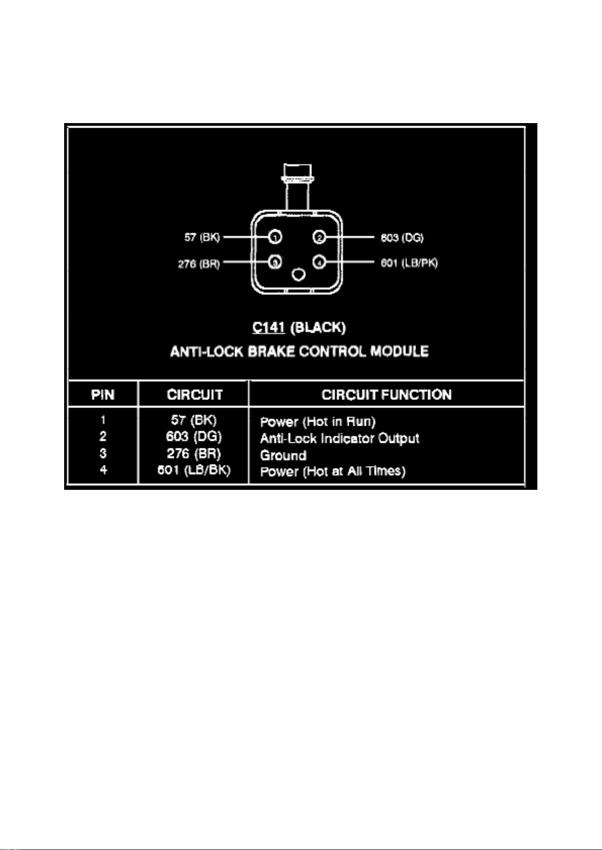
Anti-Lock Brake Control Module (C141)
Page 62
Ford Mustang Cobra Workshop Manual (V8-281 4.6L DOHC VIN V MFI (1997))
Ford Workshop Manuals > Relays and Modules > Relays and Modules - Brakes and Traction Control > Electronic Brake
Control Module > Component Information > Locations > Page 62
Electronic Brake Control Module: Description and Operation
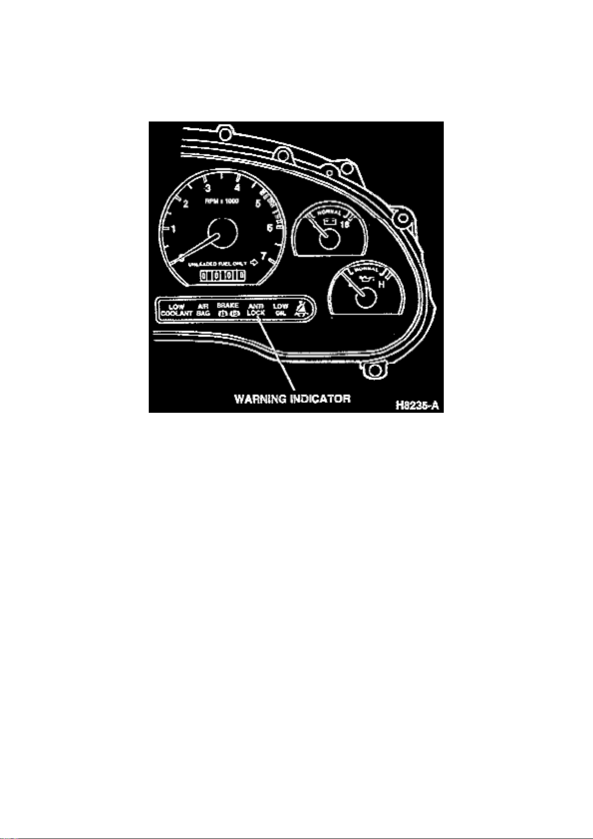
Anti-Lock Brake Warning Indicator
DESCRIPTION
The anti-lock brake control module monitors wheel speed and controls anti-lock brake system
(ABS) function. It also has on-board diagnostic (OBD) capabilities and stores diagnostic trouble
codes (DTCs) in its memory.
OPERATION
When the anti-lock brake control module detects an impending wheel lock, it modulates brake
pressure to the appropriate brake caliper. The anti-lock brake control module receives wheel speed
readings from each brake anti-lock sensor, and uses this information to compare wheel speeds. By
continuously monitoring and comparing the rotational speed of each wheel, the anti-lock brake
control module activates the anti-lock braking system only when it senses an impending wheel
lock-up under severe braking conditions. The anti-lock brake control module decides which brakes
need to be controlled, and sends the appropriate signals to the Hydraulic Control Unit (hydraulic
portion of the assembly). Impending wheel lock conditions trigger signals from the Hydraulic
Control Unit that open and close the appropriate modulator solenoid valves. This may result in
moderate pulsations in the brake pedal when applied. During normal braking (non-ABS stop),
brake pedal feel will be the same as a vehicle with a standard brake system (non-ABS).
DTCs
If a fault is detected in the system, a DTC will be stored in the anti-lock brake control module
memory, and the instrument panel ANTI-LOCK warning indicator will illuminate when the engine is
Page 63

running. The anti-lock brake control module has the ability to store three DTCs in memory.
Page 64
Ford Mustang Cobra Workshop Manual (V8-281 4.6L DOHC VIN V MFI (1997))
Ford Workshop Manuals > Relays and Modules > Relays and Modules - Brakes and Traction Control > Electronic Brake
Control Module > Component Information > Locations > Page 63
Page 65

Electronic Brake Control Module: Service and Repair
HYDRAULIC CONTROL UNIT REMOVAL
Hydraulic Control Unit Assembly
1. Disconnect battery ground cable. 2. Disconnect two wiring harnesses from the hydraulic control
unit. 3. Disconnect five brake tubes. 4. Remove hydraulic control unit ground wire. 5. Remove four
bolts. 6. Remove hydraulic control unit from the vehicle. 7. Remove three nuts and mounting
bracket from the hydraulic control unit.
DISASSEMBLY
Anti-Lock Brake Control Module/Hydraulic Control Unit
Page 66

Ford Mustang Cobra Workshop Manual (V8-281 4.6L DOHC VIN V MFI (1997))
Ford Workshop Manuals > Relays and Modules > Relays and Modules - Brakes and Traction Control > Electronic Brake
Control Module > Component Information > Locations > Page 64
Page 67

1. Remove TORX(R) head screw from black plastic cover and remove cover. 2. Remove 15 pin
connector. 3. Remove 4 pin connector. 4. Remove six TORX(R) head bolts securing anti-lock
brake control module to hydraulic control unit. 5. Remove anti-lock brake control module by pulling
straight up over ground post.
REASSEMBLY
1. Position anti-lock brake control module over ground post. 2. Install six TORX(R) bolts and secure
anti-lock brake control module to the hydraulic control unit. 3. Install 4 pin and 15 pin connector. 4.
Install cover and secure with screw.
INSTALLATION
1. Install three nuts and mounting bracket on the hydraulic control unit and tighten nuts to 10-20
Nm (89-177 inch lbs.). 2. Install hydraulic control unit and four bolts. Tighten bottom bolts to 10-14
Nm (89-123 inch lbs.). Tighten remaining bolts to 18-26 Nm (14-19 ft.
lbs.).
3. Install hydraulic control unit ground wire and screw. Tighten to 3.4-4.8 Nm (30-42 inch lbs.). 4.
Connect five brake tubes to hydraulic control unit. 5. Connect two wiring harnesses. 6. Connect
battery ground cable.
NOTE: Service to the ABS valve block and pump and motor assembly does not require any special
bleeding procedure. Follow manual or pressure bleeding procedures.
7. Bleed brake system.
Page 68

Ford Mustang Cobra Workshop Manual (V8-281 4.6L DOHC VIN V MFI (1997))
Ford Workshop Manuals > Relays and Modules > Relays and Modules - Cooling System > Radiator Cooling Fan Control
Module > Component Information > Specifications
Page 69

Radiator Cooling Fan Control Module: Specifications
Wiring Harness Bolt .............................................................................................................................
.................................... 1.3-2.0 Nm (12-18 inch lbs.)
Page 70

Ford Mustang Cobra Workshop Manual (V8-281 4.6L DOHC VIN V MFI (1997))
Ford Workshop Manuals > Relays and Modules > Relays and Modules - Cooling System > Radiator Cooling Fan Control
Module > Component Information > Specifications > Page 69
Page 71

Radiator Cooling Fan Control Module: Description and Operation
PURPOSE
The Constant Control Relay Module (CCRM) interfaces with the Powertrain Control Module (PCM)
to provide control of the cooling fan and A/C clutch. The module includes the PCM power relay to
provide power to the PCM. These relays are contained in one housing, resulting in longer service
life and reduced wiring requirements for operation.
CONSTRUCTION
The CCRM has one 24-pin connector. Relays contained in the housing are independent of one
another.
OPERATION
The relays contained within the CCRM are interdependent and work with each other. The following
describes the different relay functions within the CCRM:
EEC Power Relay
For any other circuit in the CCRM to operate, this circuit must be powered up. This prevents
actuators from being turned on without the EEC system having control over them.
Fuel Pump Relay
The fuel pump relay circuit controls the fuel pump. The PCM provides the ground circuit for the
primary side of the relay. The secondary side supplies Battery Voltage (B+) to the fuel pump itself.
Cooling Fan Motor Relay
The cooling fan motor is controlled during vehicle operation by the constant control relay module
(CCRM)(12B581) and powertrain control module (PCM)(12A650) which energizes the cooling fan
motor under the following conditions: -
When the engine temperature is higher than normal the cooling fan motor starts operating at 105°C
(221°F) and stops when temperature drops to 94°C (200°F).
- When vehicle A/C is on and vehicle speed does not provide enough natural airflow, the cooling
fan motor starts running at or below 69 km/h (43 mph) and stops at 77 km/h (48 mph).
Low Fan Control Relay
The Low Fan Control (LFC) relay controls the electric cooling fan. The primary control circuit of the
LFC relay is normally high (B+). In this state the low speed cooling fan runs continuously. To turn
the fan off, The PCM grounds this circuit, pulling it low (near zero volts). A "fail safe" is built into the
LFC circuit to run the fan anytime the EEC power relay is activated, should the PCM fail open
circuit.
High Fan Control Relay
The High Fan Control (HFC) relay circuit operates the high speed electric cooling fan. If the Engine
Coolant Temperature (ECT) sensor relays a high temperature or overheat condition to the PCM, it
activates the HFC. In order to turn the high speed cooling fan on, the PCM grounds the primary
circuit of the HFC relay. The secondary circuit applies B+ to the cooling fan motor.
Wide Open Throttle A/C Control Relay
This circuit controls the A/C compressor clutch during normal operation. This circuit also
disengages the A/C clutch as commanded by the PCM during Wide Open Throttle (WOT)
Page 72

conditions. This solid state relay has two control circuits. One is used to engage the A/C clutch
upon demand from the vehicle operator and the A/C cycling pressure switch. The other control is
used to disengage the clutch upon command from the PCM.
Power Ground
This circuit provides the CCRM with a ground source for operating various controls. The circuit
uses one pin that goes to the battery negative terminal.
Page 73
Ford Mustang Cobra Workshop Manual (V8-281 4.6L DOHC VIN V MFI (1997))
Ford Workshop Manuals > Relays and Modules > Relays and Modules - Cooling System > Radiator Cooling Fan Control
Module > Component Information > Specifications > Page 70
Radiator Cooling Fan Control Module: Service and Repair
REMOVAL
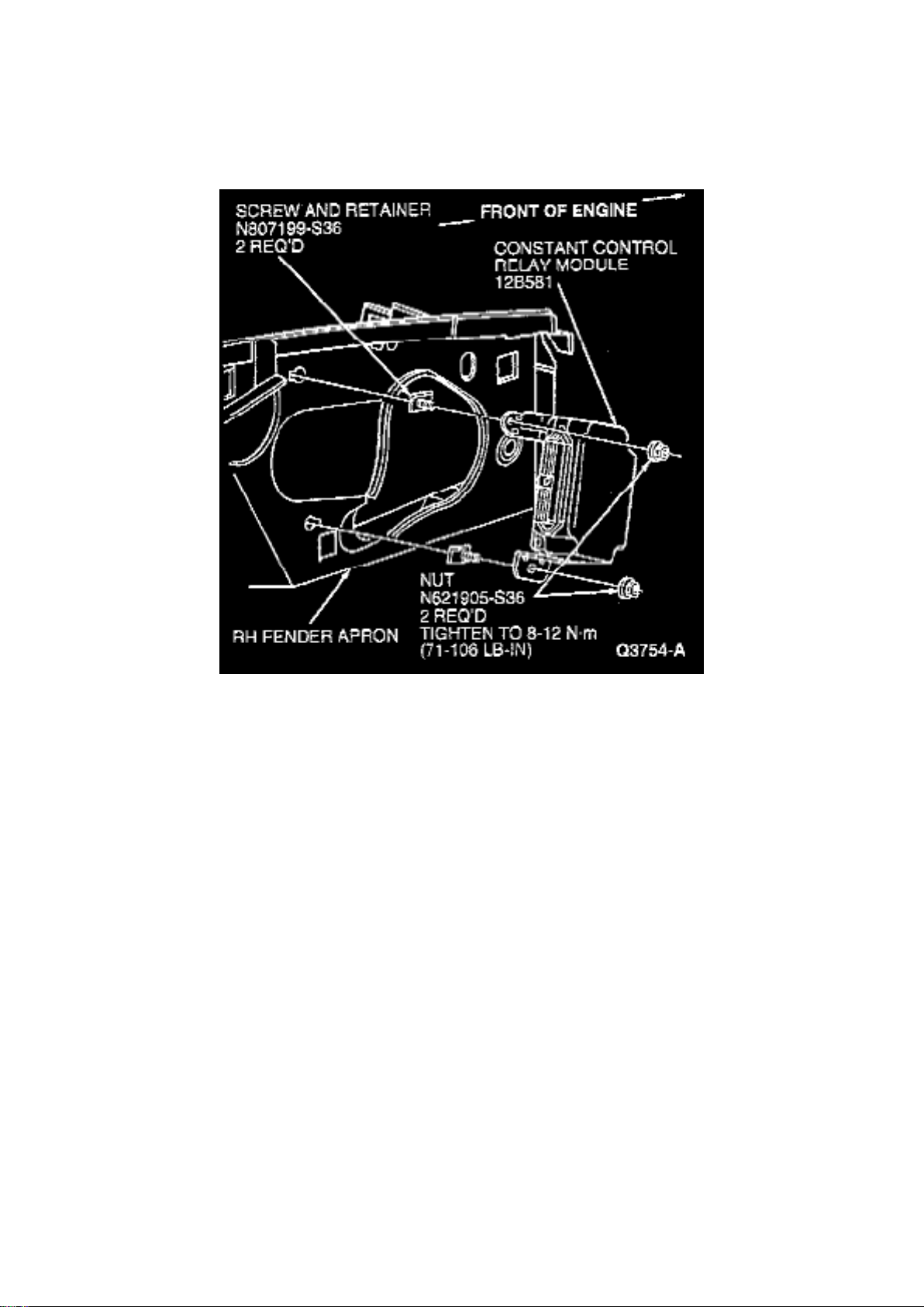
1. Remove constant control relay module retaining nuts. 2. Remove engine control sensor wiring
(12A581) from constant control relay module.
INSTALLATION
1. Follow removal procedure in reverse order. 2. Tighten retaining nuts to 8-12 Nm (6-8 ft. lbs.).
Page 74

Ford Mustang Cobra Workshop Manual (V8-281 4.6L DOHC VIN V MFI (1997))
Ford Workshop Manuals > Relays and Modules > Relays and Modules - Cooling System > Radiator Cooling Fan Motor
Relay > Component Information > Technical Service Bulletins > Engine Cooling Fan Module - Service Information
Page 75

Radiator Cooling Fan Motor Relay: Technical Service Bulletins Engine Cooling Fan Module Service Information
Article No. 97-10-4
05/12/97
^ ENGINE COOLING FAN - MODULE COMPONENT SERVICE INFORMATION
^ COOLING FAN - MODULE COMPONENT SERVICE INFORMATION
FORD: 1994-97 ESCORT, MUSTANG, TAURUS 1995-97 CONTOUR
LINCOLN-MERCURY: 1994-97 CONTINENTAL, MARK VIII, SABLE, TRACER 1995-97
MYSTIQUE
LIGHT TRUCK: 1994-97 VILLAGER, WINDSTAR
ISSUE: Currently, Service Manuals indicate that the Motor and Fan Assembly-Engine Cooling
(-80607-) should/can be serviced at the component level: Engine Cooling Fan Motor (-8k621-),
Shroud (-8146-), and Fan Blade (-8600-). This information is incorrect. The Motor and Fan
Assembly-Engine Cooling (-8C607-) should only be serviced as an assembly. The assembly is
dynamically balanced at the Original Equipment Manufacturer and should not be disassembled into
its component parts. If the assembly is serviced at the component level, the assembly balance
could be adversely affected, and a possible durability and Noise/Vibration/Harshness (NVH) issue
may arise.
ACTION: Service only the Motor and Fan Assembly-Engine Cooling (-8C607-). Do not service the
Engine Cooling Fan Motor (-8K621-), Shroud (-8146-), or the Fan Blade (-8600-). Servicing only
the assembly will eliminate durability and NVH issues related to component replacement. Refer to
the following text for details.
Electric Cooling Fan Blades (-8600-), Motors (-8K621-), and Shrouds (-8146-) will no longer be
serviced separately. These components will only be serviced in Cooling Fan Module Assemblies
(-8C607-). Refer to the Ford Part Manuals Base (-8C607-) for part number.
OTHER APPLICABLE ARTICLES: NONE WARRANTY STATUS: INFORMATION ONLY OASIS
CODES: 208000, 208999, 290000, 402000, 490000, 702000
Page 76
Ford Mustang Cobra Workshop Manual (V8-281 4.6L DOHC VIN V MFI (1997))
Ford Workshop Manuals > Relays and Modules > Relays and Modules - Cooling System > Radiator Cooling Fan Motor
Relay > Component Information > Technical Service Bulletins > Page 75
Page 77

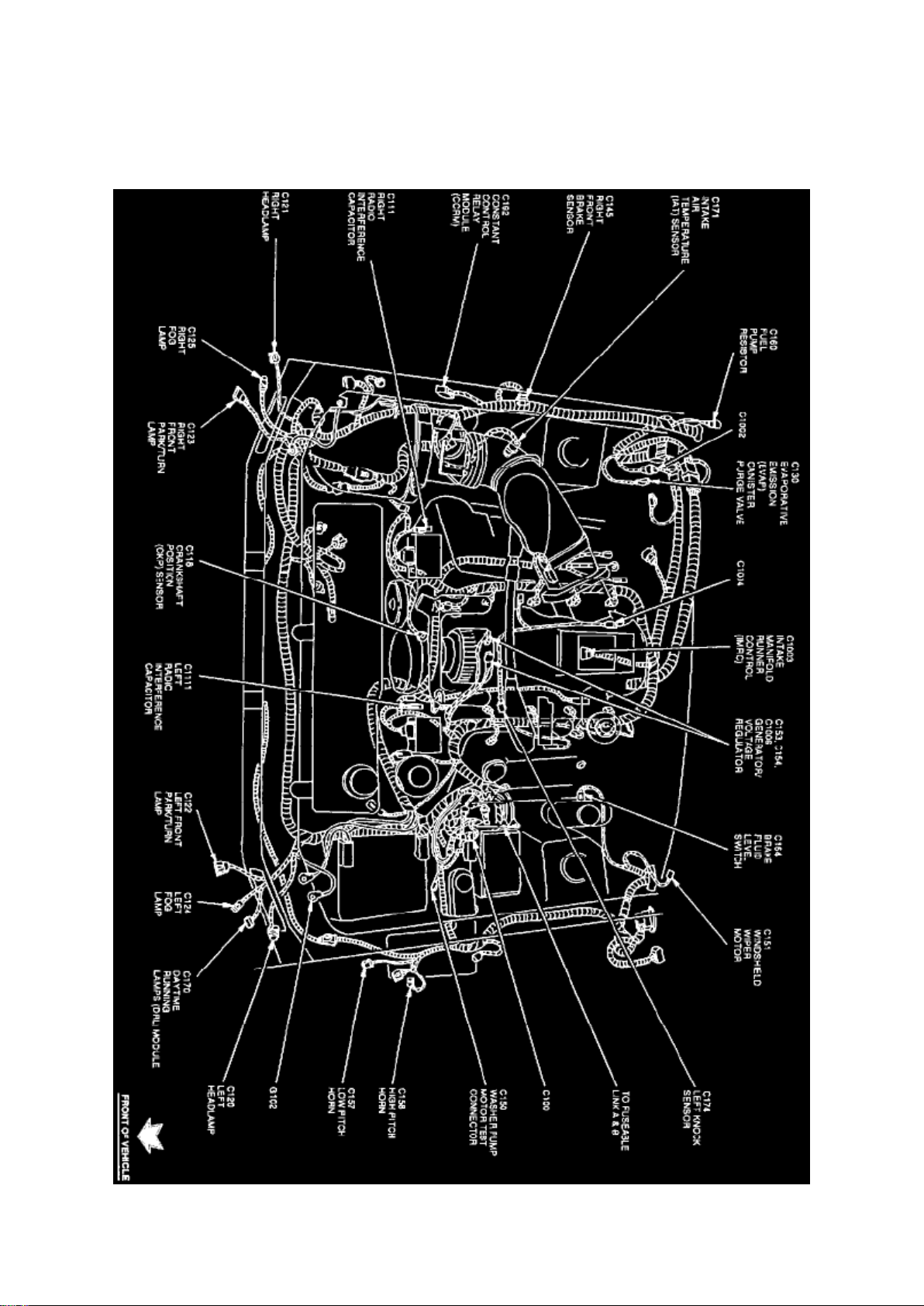
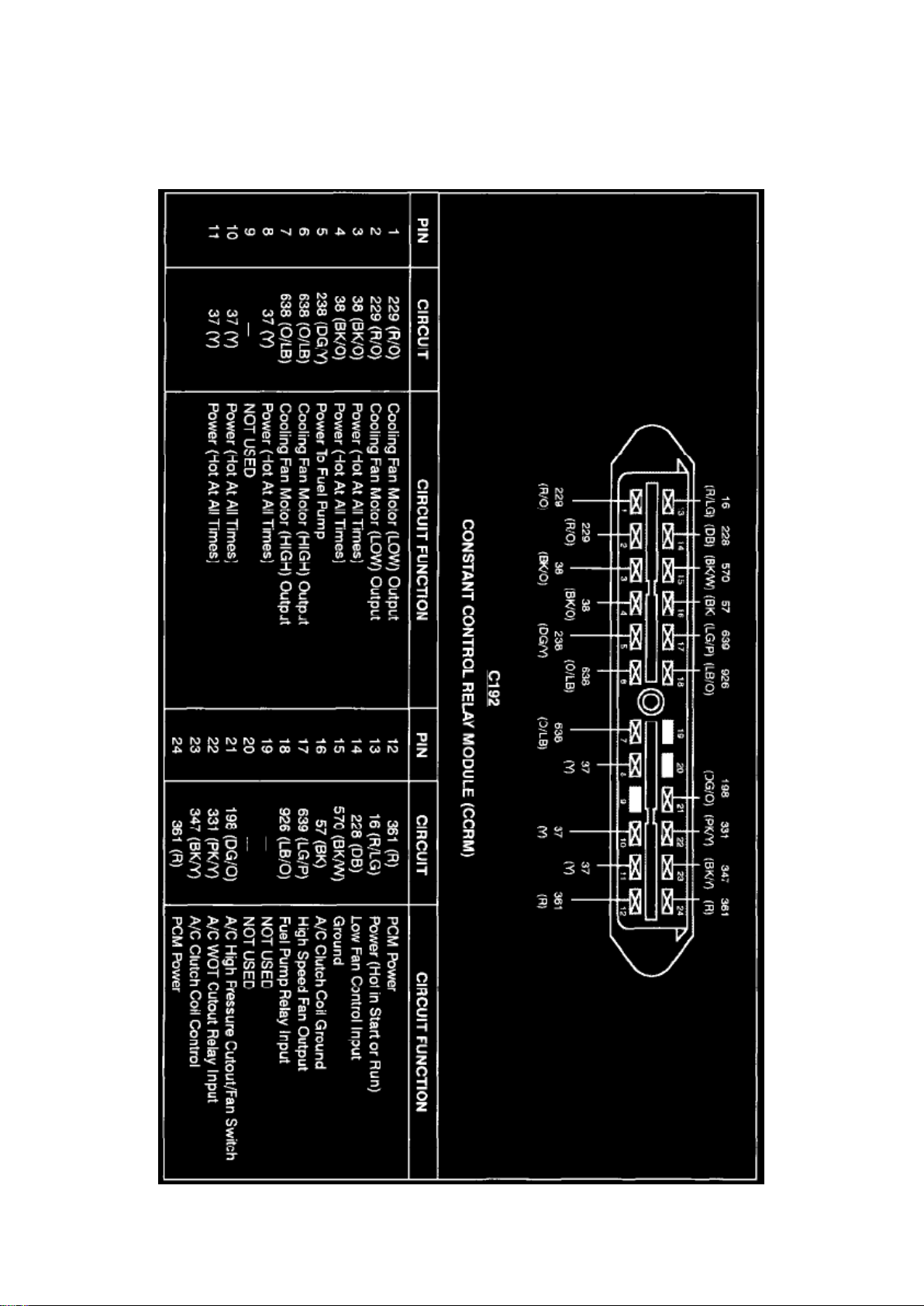
Radiator Cooling Fan Motor Relay: Locations
Engine View
Page 78
Ford Mustang Cobra Workshop Manual (V8-281 4.6L DOHC VIN V MFI (1997))
Ford Workshop Manuals > Relays and Modules > Relays and Modules - Cooling System > Radiator Cooling Fan Motor
Relay > Component Information > Technical Service Bulletins > Page 76
Page 79

Constant Control Relay Module
Page 80

Ford Mustang Cobra Workshop Manual (V8-281 4.6L DOHC VIN V MFI (1997))
Ford Workshop Manuals > Relays and Modules > Relays and Modules - Cooling System > Radiator Cooling Fan Motor
Relay > Component Information > Technical Service Bulletins > Page 77
Page 81

Radiator Cooling Fan Motor Relay: Description and Operation
PURPOSE
The Constant Control Relay Module (CCRM) interfaces with the Powertrain Control Module (PCM)
to provide control of the cooling fan and A/C clutch. The module includes the PCM power relay to
provide power to the PCM. These relays are contained in one housing, resulting in longer service
life and reduced wiring requirements for operation.
CONSTRUCTION
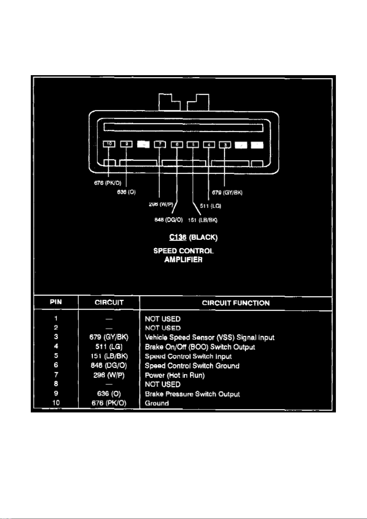
The CCRM has one 24-pin connector. Relays contained in the housing are independent of one
another.
OPERATION
The relays contained within the CCRM are interdependent and work with each other. The following
describes the different relay functions within the CCRM:
EEC Power Relay
For any other circuit in the CCRM to operate, this circuit must be powered up. This prevents
actuators from being turned on without the EEC system having control over them.
Fuel Pump Relay
The fuel pump relay circuit controls the fuel pump. The PCM provides the ground circuit for the
primary side of the relay. The secondary side supplies Battery Voltage (B+) to the fuel pump itself.
Cooling Fan Motor Relay
The cooling fan motor is controlled during vehicle operation by the constant control relay module
(CCRM)(12B581) and powertrain control module (PCM)(12A650) which energizes the cooling fan
motor under the following conditions: -
When the engine temperature is higher than normal the cooling fan motor starts operating at 105°C
(221°F) and stops when temperature drops to 94°C (200°F).
- When vehicle A/C is on and vehicle speed does not provide enough natural airflow, the cooling
fan motor starts running at or below 69 km/h (43 mph) and stops at 77 km/h (48 mph).
Low Fan Control Relay
The Low Fan Control (LFC) relay controls the electric cooling fan. The primary control circuit of the
LFC relay is normally high (B+). In this state the low speed cooling fan runs continuously. To turn
the fan off, The PCM grounds this circuit, pulling it low (near zero volts). A "fail safe" is built into the
LFC circuit to run the fan anytime the EEC power relay is activated, should the PCM fail open
circuit.
High Fan Control Relay
The High Fan Control (HFC) relay circuit operates the high speed electric cooling fan. If the Engine
Coolant Temperature (ECT) sensor relays a high temperature or overheat condition to the PCM, it
activates the HFC. In order to turn the high speed cooling fan on, the PCM grounds the primary
circuit of the HFC relay. The secondary circuit applies B+ to the cooling fan motor.
Wide Open Throttle A/C Control Relay
This circuit controls the A/C compressor clutch during normal operation. This circuit also
disengages the A/C clutch as commanded by the PCM during Wide Open Throttle (WOT)
Page 82

conditions. This solid state relay has two control circuits. One is used to engage the A/C clutch
upon demand from the vehicle operator and the A/C cycling pressure switch. The other control is
used to disengage the clutch upon command from the PCM.
Power Ground
This circuit provides the CCRM with a ground source for operating various controls. The circuit
uses one pin that goes to the battery negative terminal.
Page 83
Ford Mustang Cobra Workshop Manual (V8-281 4.6L DOHC VIN V MFI (1997))
Ford Workshop Manuals > Relays and Modules > Relays and Modules - Cruise Control > Cruise Control Module >
Component Information > Diagrams
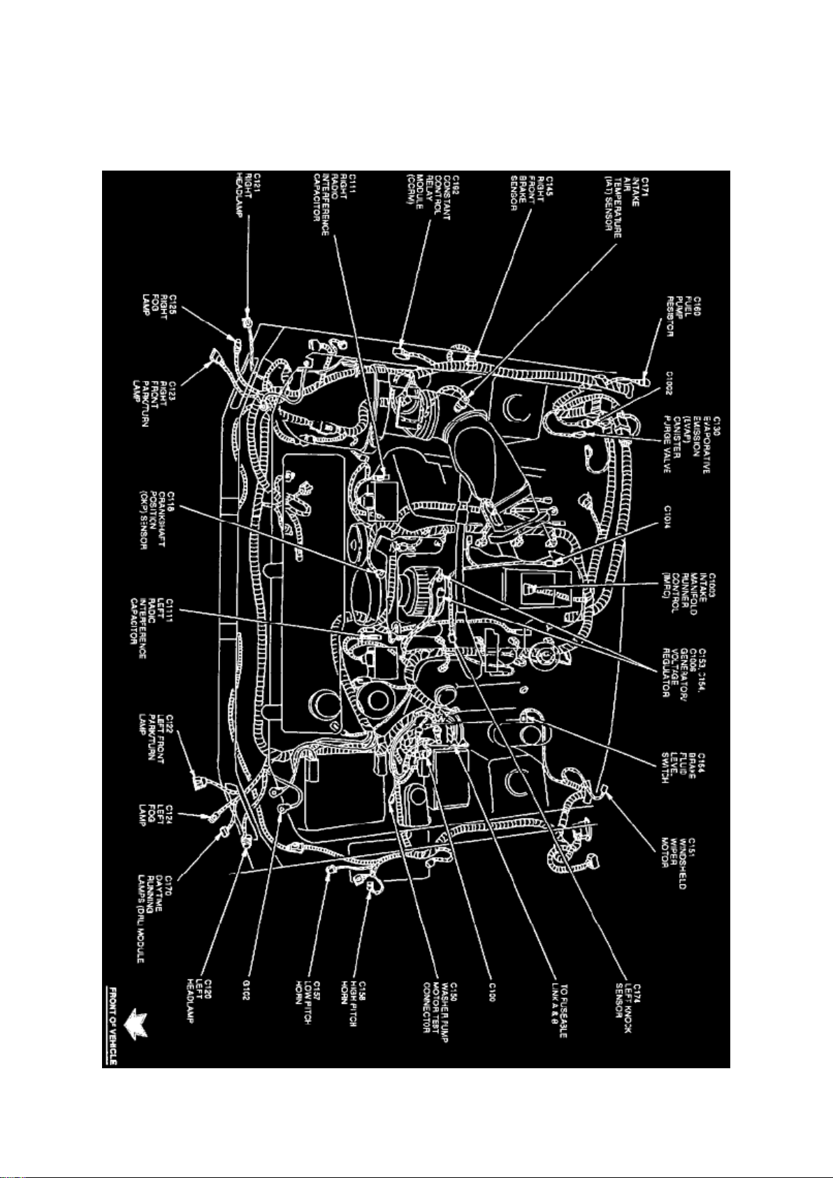
Speed Control Amplifier
Page 84
Ford Mustang Cobra Workshop Manual (V8-281 4.6L DOHC VIN V MFI (1997))
Ford Workshop Manuals > Relays and Modules > Relays and Modules - HVAC > Compressor Clutch Relay > Component
Information > Locations
Page 85

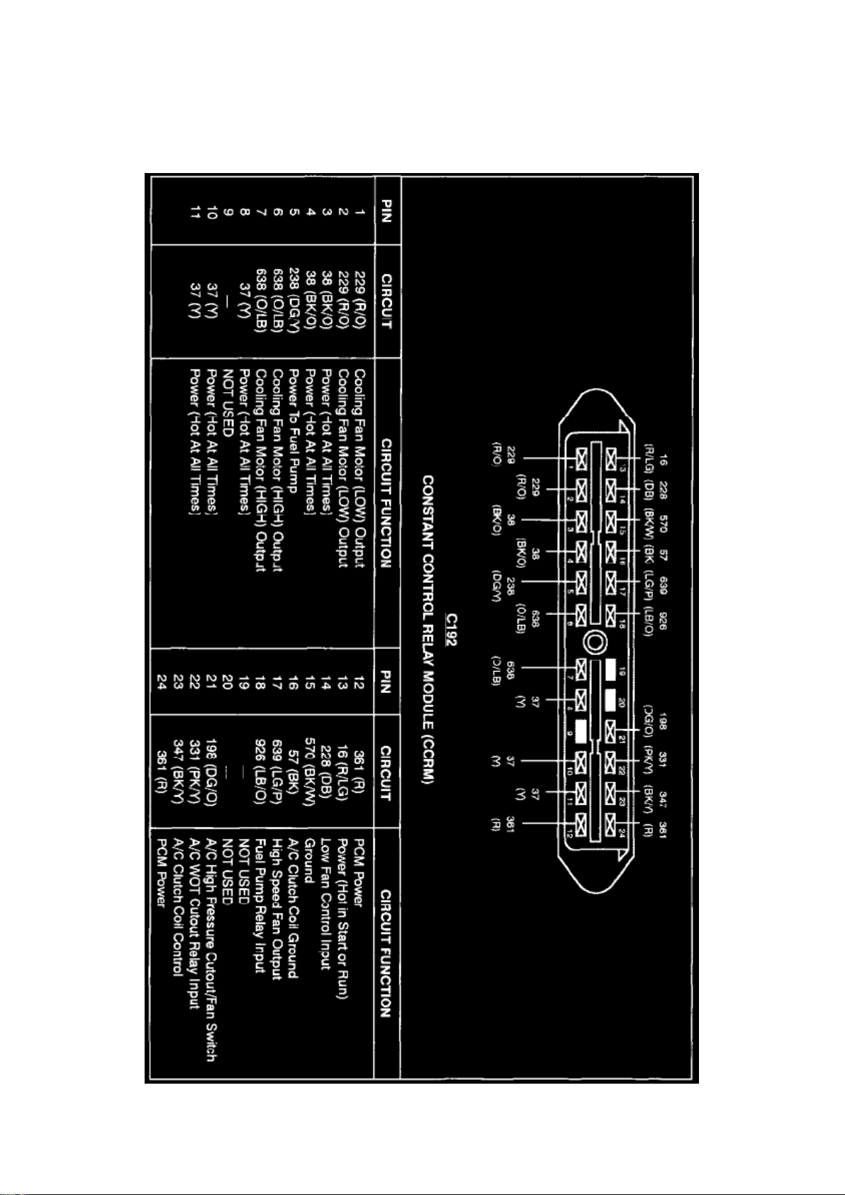
Compressor Clutch Relay: Locations
Engine View
Page 86
Ford Mustang Cobra Workshop Manual (V8-281 4.6L DOHC VIN V MFI (1997))
Ford Workshop Manuals > Relays and Modules > Relays and Modules - HVAC > Compressor Clutch Relay > Component
Information > Locations > Page 86
Page 87

Constant Control Relay Module
Page 88

Ford Mustang Cobra Workshop Manual (V8-281 4.6L DOHC VIN V MFI (1997))
Ford Workshop Manuals > Relays and Modules > Relays and Modules - HVAC > Compressor Clutch Relay > Component
Information > Locations > Page 87
Page 89

Compressor Clutch Relay: Description and Operation
PURPOSE
The Constant Control Relay Module (CCRM) interfaces with the Powertrain Control Module (PCM)
to provide control of the cooling fan and A/C clutch. The module includes the PCM power relay to
provide power to the PCM. These relays are contained in one housing, resulting in longer service
life and reduced wiring requirements for operation.
CONSTRUCTION
The CCRM has one 24-pin connector. Relays contained in the housing are independent of one
another.
OPERATION
The relays contained within the CCRM are interdependent and work with each other. The following
describes the different relay functions within the CCRM:
EEC Power Relay
For any other circuit in the CCRM to operate, this circuit must be powered up. This prevents
actuators from being turned on without the EEC system having control over them.
Fuel Pump Relay
The fuel pump relay circuit controls the fuel pump. The PCM provides the ground circuit for the
primary side of the relay. The secondary side supplies Battery Voltage (B+) to the fuel pump itself.
Cooling Fan Motor Relay
The cooling fan motor is controlled during vehicle operation by the constant control relay module
(CCRM)(12B581) and powertrain control module (PCM)(12A650) which energizes the cooling fan
motor under the following conditions: -
When the engine temperature is higher than normal the cooling fan motor starts operating at 105°C
(221°F) and stops when temperature drops to 94°C (200°F).
- When vehicle A/C is on and vehicle speed does not provide enough natural airflow, the cooling
fan motor starts running at or below 69 km/h (43 mph) and stops at 77 km/h (48 mph).
Low Fan Control Relay
The Low Fan Control (LFC) relay controls the electric cooling fan. The primary control circuit of the
LFC relay is normally high (B+). In this state the low speed cooling fan runs continuously. To turn
the fan off, The PCM grounds this circuit, pulling it low (near zero volts). A "fail safe" is built into the
LFC circuit to run the fan anytime the EEC power relay is activated, should the PCM fail open
circuit.
High Fan Control Relay
The High Fan Control (HFC) relay circuit operates the high speed electric cooling fan. If the Engine
Coolant Temperature (ECT) sensor relays a high temperature or overheat condition to the PCM, it
activates the HFC. In order to turn the high speed cooling fan on, the PCM grounds the primary
circuit of the HFC relay. The secondary circuit applies B+ to the cooling fan motor.
Wide Open Throttle A/C Control Relay
This circuit controls the A/C compressor clutch during normal operation. This circuit also
disengages the A/C clutch as commanded by the PCM during Wide Open Throttle (WOT)
Page 90

conditions. This solid state relay has two control circuits. One is used to engage the A/C clutch
upon demand from the vehicle operator and the A/C cycling pressure switch. The other control is
used to disengage the clutch upon command from the PCM.
Power Ground
This circuit provides the CCRM with a ground source for operating various controls. The circuit
uses one pin that goes to the battery negative terminal.
Page 91
Ford Mustang Cobra Workshop Manual (V8-281 4.6L DOHC VIN V MFI (1997))
Ford Workshop Manuals > Relays and Modules > Relays and Modules - Instrument Panel > Audible Warning Device
Control Module > Component Information > Locations
Page 92

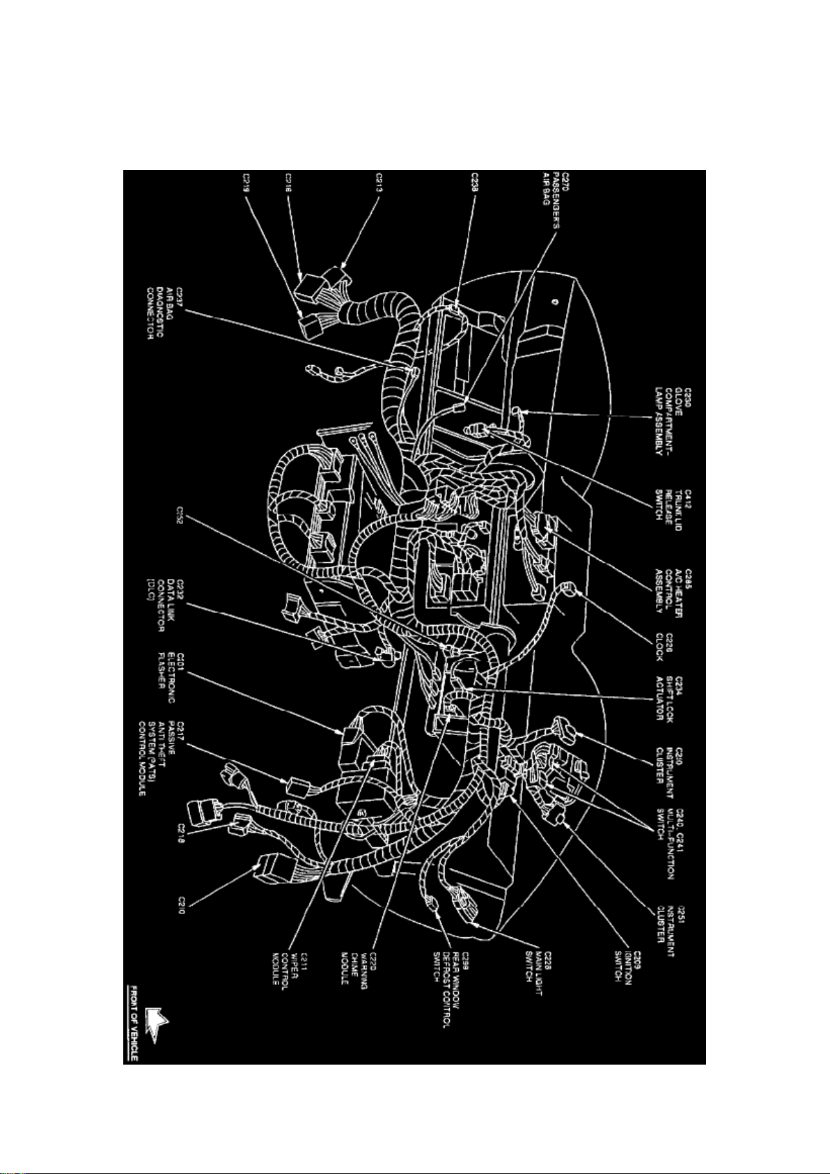
Audible Warning Device Control Module: Locations
Instrument Panel View
The Warning Chime Module is located behind center of the instrument panel, RH side of the radio.
Page 93
Ford Mustang Cobra Workshop Manual (V8-281 4.6L DOHC VIN V MFI (1997))
Ford Workshop Manuals > Relays and Modules > Relays and Modules - Instrument Panel > Audible Warning Device
Control Module > Component Information > Locations > Page 92
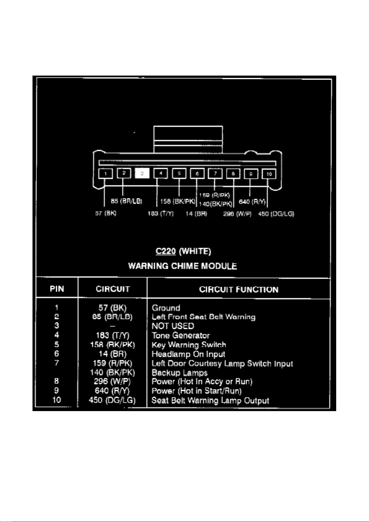
Warning Chime Module
Page 94

Ford Mustang Cobra Workshop Manual (V8-281 4.6L DOHC VIN V MFI (1997))
Ford Workshop Manuals > Relays and Modules > Relays and Modules - Instrument Panel > Audible Warning Device
Control Module > Component Information > Locations > Page 93
Page 95

Audible Warning Device Control Module: Description and Operation
WARNING CHIME SYSTEMS
The warning chime module will sound the following warnings:
- key-in-ignition warning
- safety belt warning
- headlamp switch ON warning
key-In-Ignition Warning
The warning chime sounds when the LH door is opened with the key in the ignition switch lock
cylinder:
- The chime continues to sound until the key is removed or the door is closed.
- When the key is in ignition switch lock cylinder, the ignition key warning switch is closed and
ground is supplied through Circuit 158 (Bk /Pk) to the warning chime module.
- When the LH door is open, the door lamp switch closes and power is supplied through Circuit 159
(R/Pk) to the module.
Safety Belt Warning
When ignition switch is turned to RUN or START:
- Power is supplied through Circuit 640 (R/Y) to the warning chime module.
- The module then supplies power through Circuit 450 (DG/LG) to illuminate the safety belt warning
indicator lamp for up to six seconds, whether or not the LH front safety belt is fastened. If ignition
key is quickly turned to OFF and then back to RUN, the warning lamp will illuminate for less than
six seconds.
- If the LH front safety belt is not fastened during this time, the safety belt buckle switch remains
closed, supplying ground through Circuit 85 (BR/LB) to the warning chime module and causing it to
sound for six seconds.
Headlamp Switch On Warning
The warning chime sounds when the LH door is opened while the main headlamp switch is in
headlamp or parking lamp position.
- It continues to sound until the headlamp switch is turned OFF or the door is closed.
- When the headlamp switch is in headlamp or parking lamp position, power is supplied through
Circuit 14 (BR) to the warning chime module.
- When the LH door is open, the LH door lamp switch is closed and power is supplied through
Circuit 159 (R/Pk) to the module.
Page 96

Ford Mustang Cobra Workshop Manual (V8-281 4.6L DOHC VIN V MFI (1997))
Ford Workshop Manuals > Relays and Modules > Relays and Modules - Instrument Panel > Audible Warning Device
Control Module > Component Information > Testing and Inspection > Initial Inspection and Diagnostic Overview
Page 97

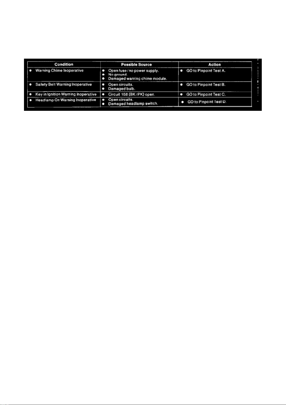
Audible Warning Device Control Module: Initial Inspection and Diagnostic Overview
Inspection and Verification
1. Verify the customer's concern by operating the warning chime system to duplicate the condition.
2. Inspect to determine if one of the following electrical concerns apply:
VISUAL INSPECTION CHART
Electrical
- Check fuse junction panel Fuses 6 (15A) 15(10A), 5(15A) or 8(10A).
- Check connectors for loose connection, damage. corrosion.
- Check circuits for shorts/opens.
3. If the inspection reveals obvious concerns that can be readily identified, service as required. 4. If
the concern(s) remains after the inspection, determine the symptom(s) and See: Symptom Related
Diagnostic Procedures
Page 98
Ford Mustang Cobra Workshop Manual (V8-281 4.6L DOHC VIN V MFI (1997))
Ford Workshop Manuals > Relays and Modules > Relays and Modules - Instrument Panel > Audible Warning Device
Control Module > Component Information > Testing and Inspection > Initial Inspection and Diagnostic Overview > Page 96
Page 99
Ford Mustang Cobra Workshop Manual (V8-281 4.6L DOHC VIN V MFI (1997))
Ford Workshop Manuals > Relays and Modules > Relays and Modules - Instrument Panel > Audible Warning Device
Control Module > Component Information > Testing and Inspection > Initial Inspection and Diagnostic Overview > Page 97
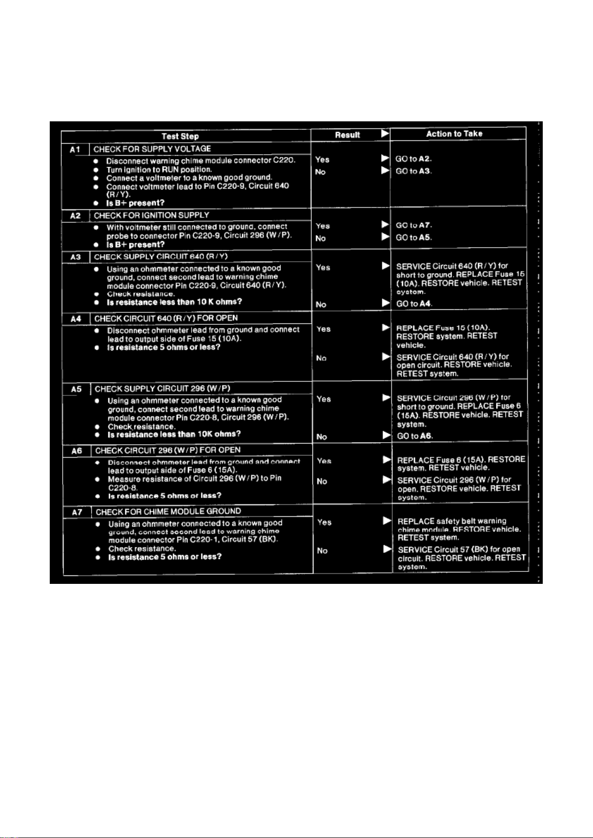
Audible Warning Device Control Module: Pinpoint Tests
Page 100
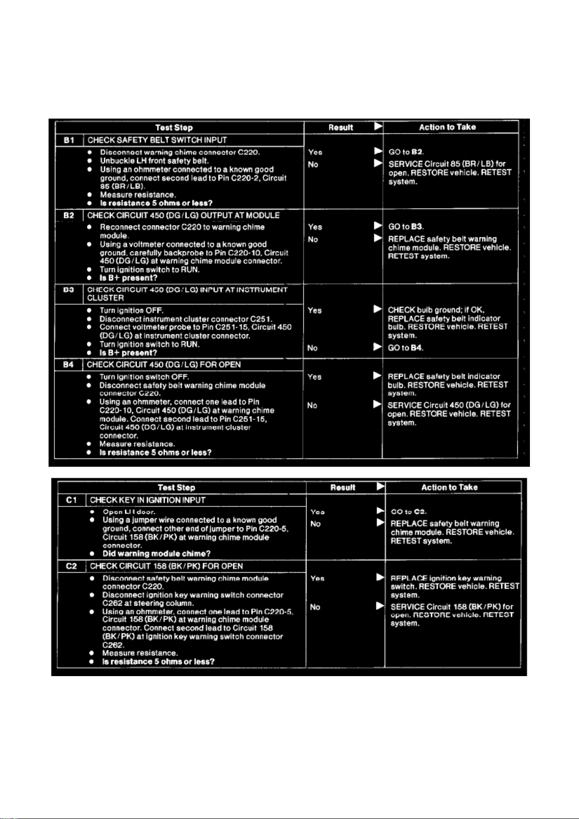
Ford Mustang Cobra Workshop Manual (V8-281 4.6L DOHC VIN V MFI (1997))
Ford Workshop Manuals > Relays and Modules > Relays and Modules - Instrument Panel > Audible Warning Device
Control Module > Component Information > Testing and Inspection > Initial Inspection and Diagnostic Overview > Page 98
 Loading...