

Page 1

Factory Workshop Manual
Ford
Mustang
V8-302 5.0L VIN M 4-bbl HP (1983)
Anonymous
1st January 2018
Make
Model
Engine and year
This manual was submitted by
Date
Page 2

Ford Mustang Workshop Manual (V8-302 5.0L VIN M 4-bbl HP (1983))
Ford Workshop Manuals > A L L Diagnostic Trouble Codes ( DTC ) > Codes by System > A L L Diagnostic Trouble Codes Engine Controls > System Information > System Diagnosis > Transmisson Codes
Page 3

A L L Diagnostic Trouble Codes - Engine Controls: Testing and Inspection Transmisson Codes
For Transmission related codes, proceed to Computers and Control Systems.
Page 4

Ford Mustang Workshop Manual (V8-302 5.0L VIN M 4-bbl HP (1983))
Ford Workshop Manuals > A L L Diagnostic Trouble Codes ( DTC ) > Codes by System > A L L Diagnostic Trouble Codes Trans and Drivetrain > System Information > System Diagnosis
Page 5

A L L Diagnostic Trouble Codes - Trans and Drivetrain: Testing and Inspection
For Transmission related codes, proceed to Computers and Control Systems.
Page 6

Ford Mustang Workshop Manual (V8-302 5.0L VIN M 4-bbl HP (1983))
Ford Workshop Manuals > Relays and Modules > Relays and Modules - Accessories and Optional Equipment > Alarm
Module, (Vehicle Antitheft) > Component Information > Technical Service Bulletins > Customer Interest for Alarm Module: >
83186 > Sep > 83 > Antitheft Module - Inoperative
Page 7

Alarm Module: Customer Interest Antitheft Module - Inoperative
Page 8

Article No. 83-18-6
ANTI-THEFT MODULE INOPERATIVE RESULTING FROM CONNECTOR CONTAMINATION
FORD ALL - 1983
LINCOLN-MERCURY ALL - 1983
An inoperative anti-theft system on 1983 vehicles built before July 1, 1983, may be caused by the
anti-theft module which has solder flux contamination present on the printed circuit board edge
connector.
Prior to performing system diagnostics and/or module replacement, clean the printed circuit
connector and the mating connector with a cloth saturated with denatured alcohol.
OTHER APPLICABLE ARTICLES: None WARRANTY STATUS: "INFORMATION ONLY"
Page 9

Ford Mustang Workshop Manual (V8-302 5.0L VIN M 4-bbl HP (1983))
Ford Workshop Manuals > Relays and Modules > Relays and Modules - Accessories and Optional Equipment > Alarm
Module, (Vehicle Antitheft) > Component Information > Technical Service Bulletins > All Technical Service Bulletins for
Alarm Module: > 83186 > Sep > 83 > Antitheft Module - Inoperative
Page 10

Alarm Module: All Technical Service Bulletins Antitheft Module - Inoperative
Page 11

Article No. 83-18-6
ANTI-THEFT MODULE INOPERATIVE RESULTING FROM CONNECTOR CONTAMINATION
FORD ALL - 1983
LINCOLN-MERCURY ALL - 1983
An inoperative anti-theft system on 1983 vehicles built before July 1, 1983, may be caused by the
anti-theft module which has solder flux contamination present on the printed circuit board edge
connector.
Prior to performing system diagnostics and/or module replacement, clean the printed circuit
connector and the mating connector with a cloth saturated with denatured alcohol.
OTHER APPLICABLE ARTICLES: None WARRANTY STATUS: "INFORMATION ONLY"
Page 12
Ford Mustang Workshop Manual (V8-302 5.0L VIN M 4-bbl HP (1983))
Ford Workshop Manuals > Relays and Modules > Relays and Modules - Body and Frame > Trunk / Liftgate Relay >
Component Information > Diagrams > Diagram Information and Instructions
Page 13

Trunk / Liftgate Relay: Diagram Information and Instructions
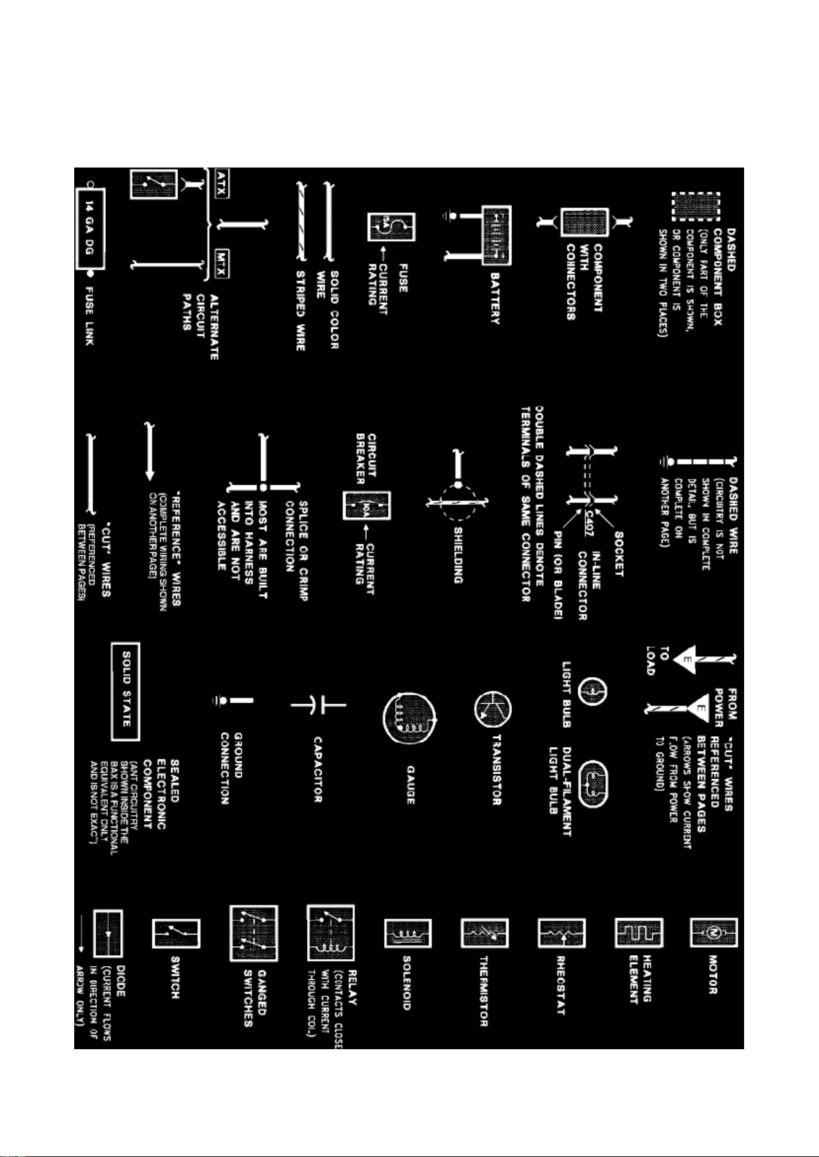
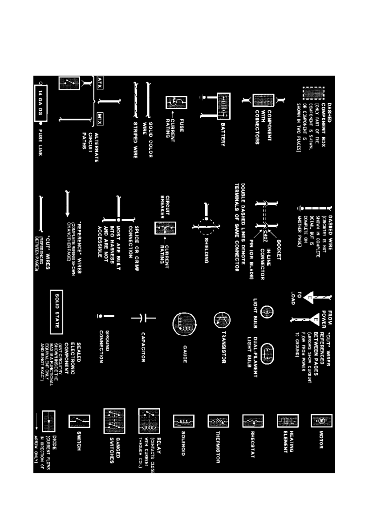
Symbol Identification
Wire Color Code Identification
NOTE: Whenever a wire is labeled with two colors; the first color listed is the basic color of the
wire, and the second color is the tracer marking of the wire. If the second color is followed by by a
D, the tracer is dots. If the second color is followed by an H, the tracer is hash marks.
For example: BR/O is a brown wire with an orange stripe, R/Y D is a red wire with yellow dots and
BK/W H is a black wire with white hash
Page 14

Ford Mustang Workshop Manual (V8-302 5.0L VIN M 4-bbl HP (1983))
Ford Workshop Manuals > Relays and Modules > Relays and Modules - Body and Frame > Trunk / Liftgate Relay >
Component Information > Diagrams > Diagram Information and Instructions > Page 31
Page 15

marks.
BL: Blue BK: Black BR: Brown DB: Dark Blue DG: Dark Green GR: Green GY: Gray LB: Light Blue
LG: Light Green N:
Natural
O: Orange
PK: Pink R:
Red
P: Purple
T: Tan
V: Violet
W: White
Y: Yellow
Page 16
Ford Mustang Workshop Manual (V8-302 5.0L VIN M 4-bbl HP (1983))
Ford Workshop Manuals > Relays and Modules > Relays and Modules - Body and Frame > Trunk / Liftgate Relay >
Component Information > Diagrams > Diagram Information and Instructions > Page 32
Page 17

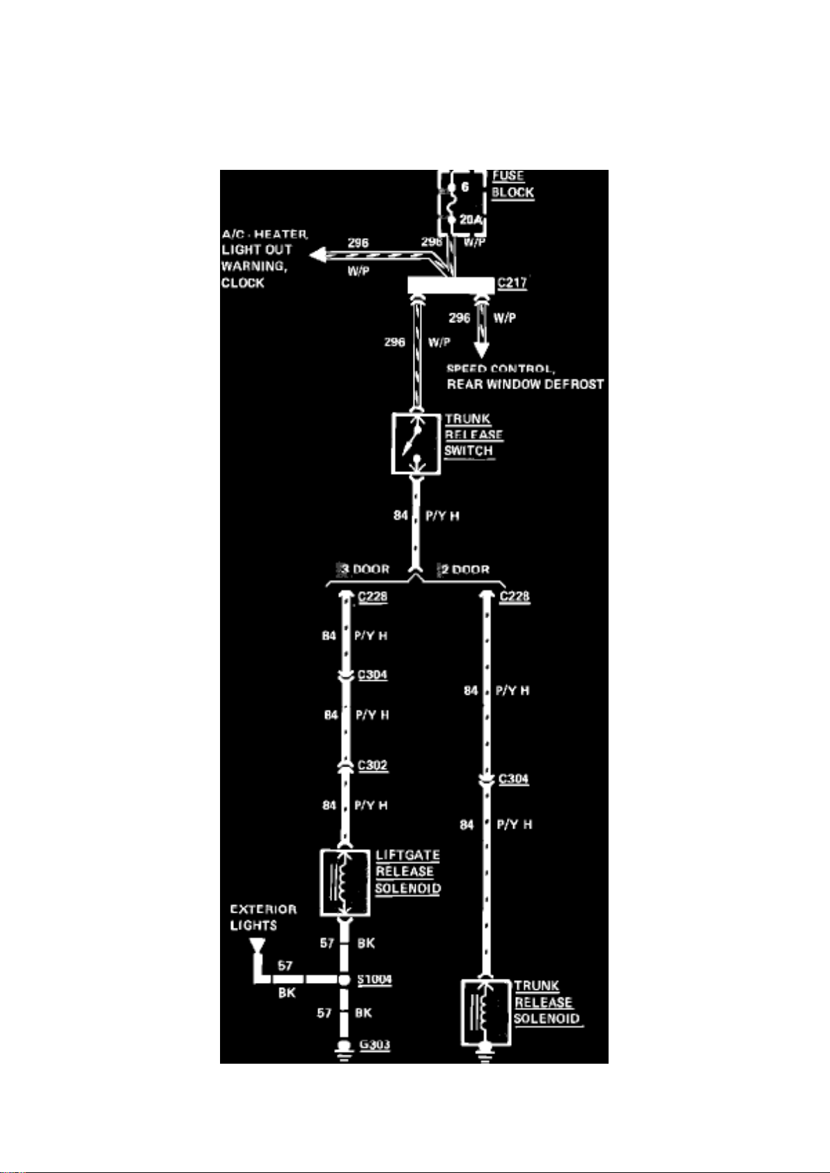
Fig. 54 Liftgate & trunk release wiring circuit. 1983-84 Capri & Mustang
Page 18

Ford Mustang Workshop Manual (V8-302 5.0L VIN M 4-bbl HP (1983))
Ford Workshop Manuals > Relays and Modules > Relays and Modules - Cruise Control > Cruise Control Module >
Component Information > Locations
Page 19

Cruise Control Module: Locations
LH Cowl Area
Page 20

Ford Mustang Workshop Manual (V8-302 5.0L VIN M 4-bbl HP (1983))
Ford Workshop Manuals > Relays and Modules > Relays and Modules - Cruise Control > Cruise Control Module >
Component Information > Locations > Page 37
Page 21

Cruise Control Module: Testing and Inspection
Use only a voltmeter of 5000 ohm/volt rating or higher when performing the following amplifier test.
``On'' Circuit Test
1. Turn ignition ``On.''
2. Connect a voltmeter between 296 and ground at the amplifier. Check battery voltage.
3. Connect a voltmeter to circuit 151 and ground at the amplifier. Voltmeter should read battery
voltage when speed control switch is ``On,'' depressed and held. If there is not voltage, refer to
``Control Switch Test.''
4. Release ``On'' button. Voltmeter should read approximately 7.8 volts, indicating the ``On'' circuit
is engaged. If voltmeter reads zero, check ground and amplifier. Also check the fuse and circuit
breaker.
Page 22

Ford Mustang Workshop Manual (V8-302 5.0L VIN M 4-bbl HP (1983))
Ford Workshop Manuals > Relays and Modules > Relays and Modules - HVAC > Compressor Clutch Relay > Component
Information > Locations
Page 23

Compressor Clutch Relay: Locations
At Carburetor
Page 24
Ford Mustang Workshop Manual (V8-302 5.0L VIN M 4-bbl HP (1983))
Ford Workshop Manuals > Relays and Modules > Relays and Modules - HVAC > Control Module HVAC > Component
Information > Locations
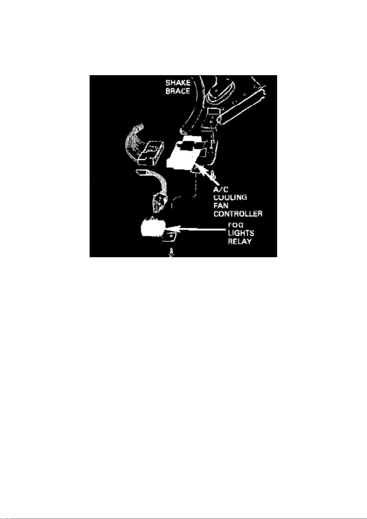
Control Module HVAC: Locations
A/C COOLING FAN CONTROLLER
Cooling Fan Controller
Attached To I/P Support
Page 25
Ford Mustang Workshop Manual (V8-302 5.0L VIN M 4-bbl HP (1983))
Ford Workshop Manuals > Relays and Modules > Relays and Modules - Lighting and Horns > Fog/Driving Lamp Relay >
Component Information > Locations
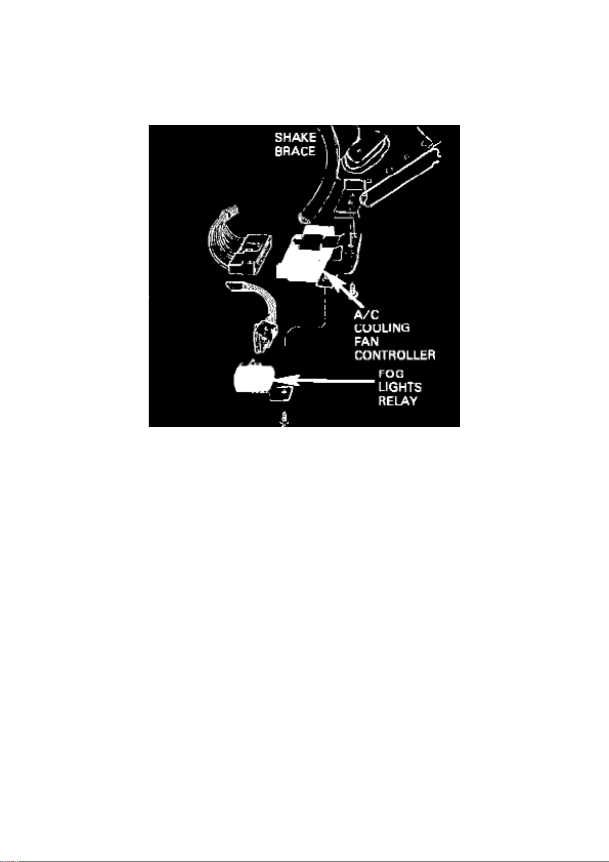
Fog/Driving Lamp Relay: Locations
Cooling Fan Controller
At Shake Brace Below Steering Column
Page 26
Ford Mustang Workshop Manual (V8-302 5.0L VIN M 4-bbl HP (1983))
Ford Workshop Manuals > Relays and Modules > Relays and Modules - Lighting and Horns > Headlamp Control Module >
Component Information > Diagrams > Diagram Information and Instructions
Page 27

Headlamp Control Module: Diagram Information and Instructions
Symbol Identification
Wire Color Code Identification
NOTE: Whenever a wire is labeled with two colors; the first color listed is the basic color of the
wire, and the second color is the tracer marking of the wire. If the second color is followed by by a
D, the tracer is dots. If the second color is followed by an H, the tracer is hash marks.
For example: BR/O is a brown wire with an orange stripe, R/Y D is a red wire with yellow dots and
BK/W H is a black wire with white hash
Page 28

Ford Mustang Workshop Manual (V8-302 5.0L VIN M 4-bbl HP (1983))
Ford Workshop Manuals > Relays and Modules > Relays and Modules - Lighting and Horns > Headlamp Control Module >
Component Information > Diagrams > Diagram Information and Instructions > Page 53
Page 29

marks.
BL: Blue BK: Black BR: Brown DB: Dark Blue DG: Dark Green GR: Green GY: Gray LB: Light Blue
LG: Light Green N:
Natural
O: Orange
PK: Pink R:
Red
P: Purple
T: Tan
V: Violet
W: White
Y: Yellow
Page 30
Ford Mustang Workshop Manual (V8-302 5.0L VIN M 4-bbl HP (1983))
Ford Workshop Manuals > Relays and Modules > Relays and Modules - Lighting and Horns > Headlamp Control Module >
Component Information > Diagrams > Diagram Information and Instructions > Page 54
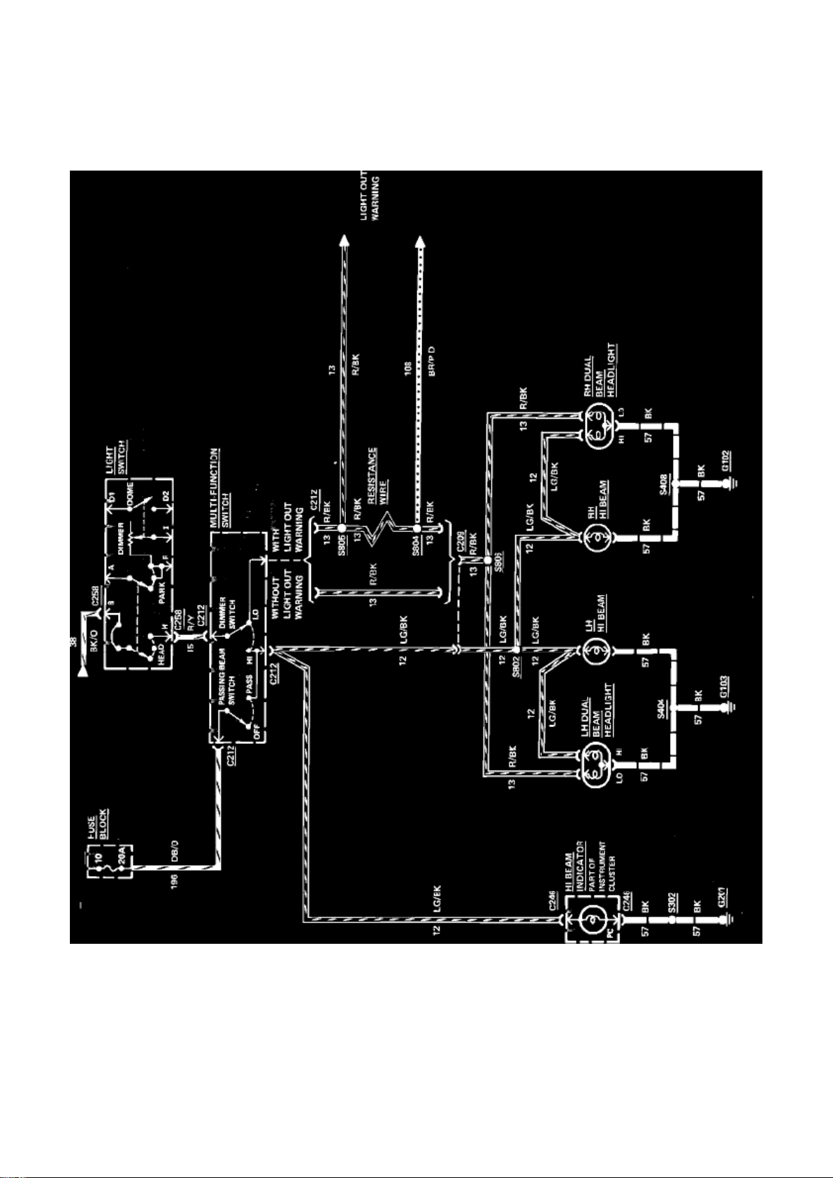
Fig. 38 Headlamp wiring circuit. 1983-84 Capri & Mustang
Page 31

Ford Mustang Workshop Manual (V8-302 5.0L VIN M 4-bbl HP (1983))
Ford Workshop Manuals > Relays and Modules > Relays and Modules - Lighting and Horns > Headlamp Dimmer Relay >
Component Information > Locations
Page 32

Headlamp Dimmer Relay: Locations
Behind I/P Right Of Column On Brace
Page 33
Ford Mustang Workshop Manual (V8-302 5.0L VIN M 4-bbl HP (1983))
Ford Workshop Manuals > Relays and Modules > Relays and Modules - Powertrain Management > Relays and Modules Computers and Control Systems > Engine Control Module > Component Information > Locations
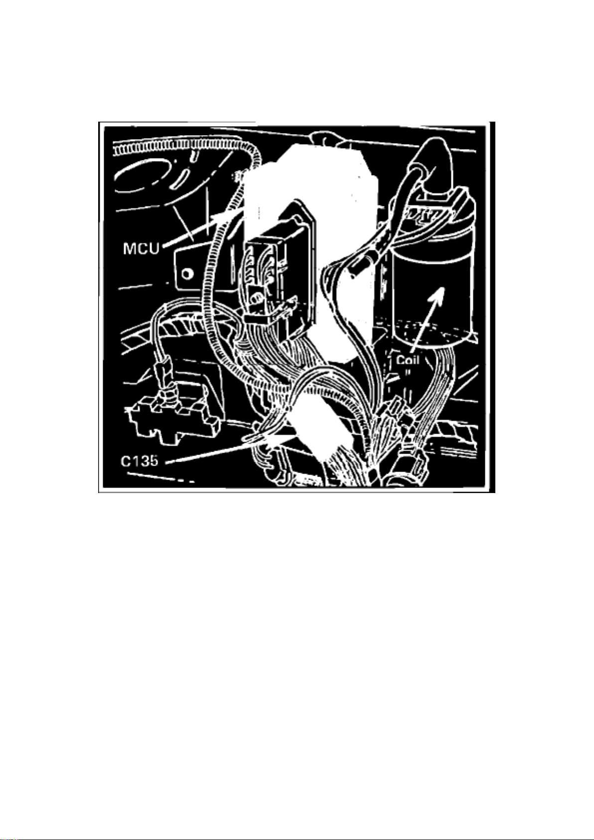
Component Location - LH Fender Duraspark II
Page 34

Ford Mustang Workshop Manual (V8-302 5.0L VIN M 4-bbl HP (1983))
Ford Workshop Manuals > Relays and Modules > Relays and Modules - Powertrain Management > Relays and Modules Computers and Control Systems > Engine Control Module > Component Information > Locations > Page 63
Page 35

Engine Control Module: Testing and Inspection
Ford provides trouble code/symptom driven diagnostics for this component. For complete diagnosis
and pinpoint testing, refer to Computers and Control Systems, Testing and Inspection.
Page 36

Ford Mustang Workshop Manual (V8-302 5.0L VIN M 4-bbl HP (1983))
Ford Workshop Manuals > Relays and Modules > Relays and Modules - Powertrain Management > Relays and Modules Computers and Control Systems > Main Relay (Computer/Fuel System) > Component Information > Locations
Page 37

Main Relay (Computer/Fuel System): Locations
On Bracket Under Passenger Seat
Page 38

Ford Mustang Workshop Manual (V8-302 5.0L VIN M 4-bbl HP (1983))
Ford Workshop Manuals > Relays and Modules > Relays and Modules - Powertrain Management > Relays and Modules Computers and Control Systems > Main Relay (Computer/Fuel System) > Component Information > Locations > Page 67
Page 39

Main Relay (Computer/Fuel System): Testing and Inspection
Ford provides trouble code/symptom driven diagnostics for this component. For complete diagnosis
and pinpoint testing, refer to Computers and Control Systems, Testing and Inspection.
Page 40

Ford Mustang Workshop Manual (V8-302 5.0L VIN M 4-bbl HP (1983))
Ford Workshop Manuals > Relays and Modules > Relays and Modules - Powertrain Management > Relays and Modules Emission Control Systems > Air Injection Pump Relay > Component Information > Locations
Page 41

Air Injection Pump Relay: Locations
Under I/P At RH Side Of Steering Column
Page 42

Ford Mustang Workshop Manual (V8-302 5.0L VIN M 4-bbl HP (1983))
Ford Workshop Manuals > Relays and Modules > Relays and Modules - Powertrain Management > Relays and Modules Fuel Delivery and Air Induction > Choke Relay > Component Information > Locations
Page 43

Choke Relay: Locations
RH Fender Apron Near Voltage Regulator
Page 44

Ford Mustang Workshop Manual (V8-302 5.0L VIN M 4-bbl HP (1983))
Ford Workshop Manuals > Relays and Modules > Relays and Modules - Powertrain Management > Relays and Modules Fuel Delivery and Air Induction > Choke Relay > Component Information > Diagrams > Diagram Information and
Instructions
Page 45
Choke Relay: Diagram Information and Instructions
Page 46

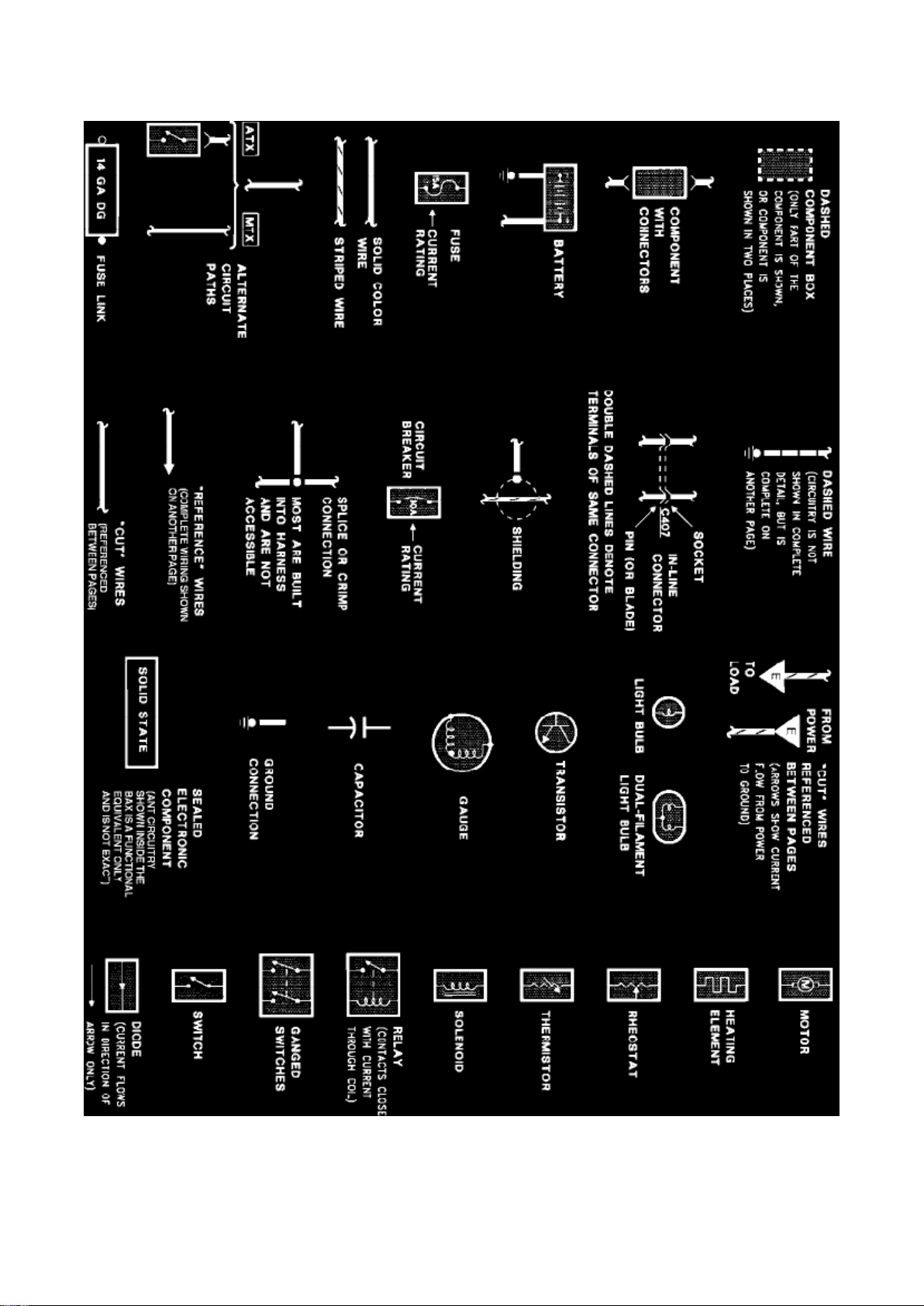
Symbol Identification
Wire Color Code Identification
NOTE: Whenever a wire is labeled with two colors; the first color listed is the basic color of the
wire, and the second color is the tracer marking of the wire. If the second color is followed by by a
D, the tracer is dots. If the second color is followed by an H, the tracer is hash marks.
For example: BR/O is a brown wire with an orange stripe, R/Y D is a red wire with yellow dots and
BK/W H is a black wire with white hash
Page 47

Ford Mustang Workshop Manual (V8-302 5.0L VIN M 4-bbl HP (1983))
Ford Workshop Manuals > Relays and Modules > Relays and Modules - Powertrain Management > Relays and Modules Fuel Delivery and Air Induction > Choke Relay > Component Information > Diagrams > Diagram Information and
Instructions > Page 78
Page 48

marks.
Page 49

BL: Blue BK: Black BR: Brown DB: Dark Blue DG: Dark Green GR: Green GY: Gray LB: Light Blue
LG: Light Green N:
Natural
O: Orange
PK: Pink R:
Red
P: Purple
T: Tan
V: Violet
W: White
Y: Yellow
Page 50

Ford Mustang Workshop Manual (V8-302 5.0L VIN M 4-bbl HP (1983))
Ford Workshop Manuals > Relays and Modules > Relays and Modules - Powertrain Management > Relays and Modules Fuel Delivery and Air Induction > Choke Relay > Component Information > Diagrams > Diagram Information and
Instructions > Page 79
Page 51
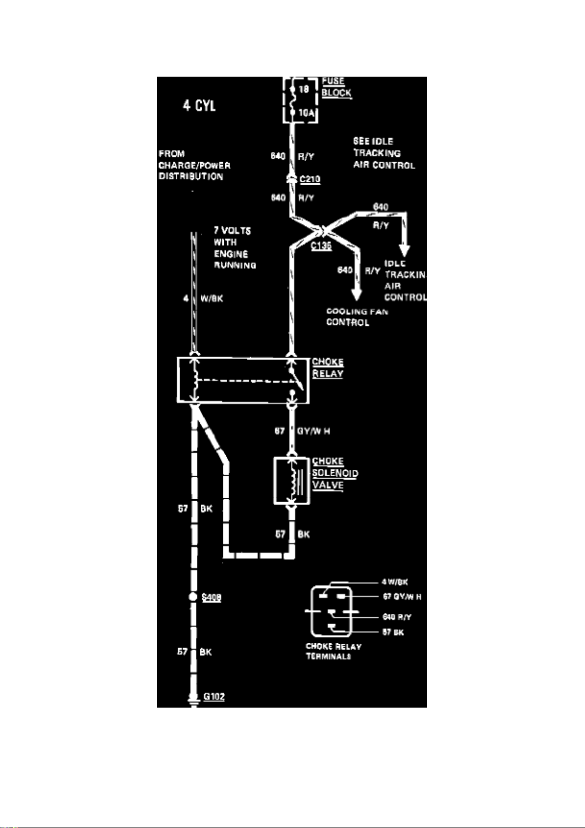
Fig. 66 Restart choke control wiring circuit. 1983 Capri & Mustang
Page 52

Ford Mustang Workshop Manual (V8-302 5.0L VIN M 4-bbl HP (1983))
Ford Workshop Manuals > Relays and Modules > Relays and Modules - Powertrain Management > Relays and Modules Fuel Delivery and Air Induction > Fuel Pump Relay > Component Information > Technical Service Bulletins > Customer
Interest for Fuel Pump Relay: > 90183 > Aug > 90 > Fuel Pump - Buzzing/Humming After Engine Shut Down
Page 53

Fuel Pump Relay: Customer Interest Fuel Pump - Buzzing/Humming After Engine Shut Down
Page 54

^ NO START - 1.9L, 2.3L, 3.0L, 3.8L, 4.9L, 5.0L, 5.8L, 7.5L - LOW STATE OF BATTERY
CHARGE
^ BATTERY - DISCHARGED - 1.9L, 2.3L, 3.0L, 3.8L, 4.9L, 5.0L, 5.8L, 7.5L
^ FUEL PUMP - NOISY - 1.9L, 2.3L, 3.0L, 3.8L, 4.9L, 5.0L, 5.8L, 7.5L
^ NOISE - "BUZZING" OR "HUMMING" FROM FUEL PUMP AFTER ENGINE IS TURNED OFF
Article No. 90-18-3 FORD:
1983-90 CROWN VICTORIA, ESCORT, EXP, MUSTANG, TEMPO, THUNDERBIRD 1986 LTD
1986-90 TAURUS
LINCOLN-MERCURY: 1983-87 LYNX
1983-90 CONTINENTAL, COUGAR, GRAND MARQUIS, MARK VII, TOPAZ, TOWN CAR 1985-86
CAPRI, MARQUIS 1986-90 SABLE
LIGHT TRUCK: 1983-90 BRONCO II, BRONCO, ECONOLINE, F-150, F-250, F-350, RANGER
1988-90 F SUPER DUTY
ISSUE: A "buzzing" or "humming" noise from the fuel pump may occur after the engine has been
shut off. There may also be a no start condition or a discharged battery. These conditions are
caused by a sticking fuel pump relay.
ACTION: Install a new fuel pump relay. Refer to the following procedure for service details.
1. Check the fuel pump relay circuit for proper operation. Refer to the appropriate EVTM for
troubleshooting details.
2. Install a new fuel pump relay, if the old one is defective.
3. Check the vehicle for proper operation.
PART NUMBER PART NAME
F19Z-9345-A Fuel Pump Relay Assy.
OTHER APPLICABLE ARTICLES: None WARRANTY STATUS:
Eligible Under Basic Warranty Coverage
OPERATION DESCRIPTION TIME
901803A 1985-86 LTD/Marquis 0.6 Hr.
(includes pinpoint test)
901803A 1990 Town Car (includes 0.4 Hr.
pinpoint test)
901803A All Other Cars (includes 0.5 Hr.
pinpoint test)
901803A All Trucks (includes pinpoint 0.5 Hr.
test)
Page 55

DEALER CODING
BASIC PART NO. CONDITION CODE
9345 09
OASIS CODES: 404000, 603300, 203000, 203100, 702000
Page 56

Ford Mustang Workshop Manual (V8-302 5.0L VIN M 4-bbl HP (1983))
Ford Workshop Manuals > Relays and Modules > Relays and Modules - Powertrain Management > Relays and Modules Fuel Delivery and Air Induction > Fuel Pump Relay > Component Information > Technical Service Bulletins > All Technical
Service Bulletins for Fuel Pump Relay: > 90183 > Aug > 90 > Fuel Pump - Buzzing/Humming After Engine Shut Down
Page 57

Fuel Pump Relay: All Technical Service Bulletins Fuel Pump - Buzzing/Humming After Engine Shut
Down
Page 58

^ NO START - 1.9L, 2.3L, 3.0L, 3.8L, 4.9L, 5.0L, 5.8L, 7.5L - LOW STATE OF BATTERY
CHARGE
^ BATTERY - DISCHARGED - 1.9L, 2.3L, 3.0L, 3.8L, 4.9L, 5.0L, 5.8L, 7.5L
^ FUEL PUMP - NOISY - 1.9L, 2.3L, 3.0L, 3.8L, 4.9L, 5.0L, 5.8L, 7.5L
^ NOISE - "BUZZING" OR "HUMMING" FROM FUEL PUMP AFTER ENGINE IS TURNED OFF
Article No. 90-18-3 FORD:
1983-90 CROWN VICTORIA, ESCORT, EXP, MUSTANG, TEMPO, THUNDERBIRD 1986 LTD
1986-90 TAURUS
LINCOLN-MERCURY: 1983-87 LYNX
1983-90 CONTINENTAL, COUGAR, GRAND MARQUIS, MARK VII, TOPAZ, TOWN CAR 1985-86
CAPRI, MARQUIS 1986-90 SABLE
LIGHT TRUCK: 1983-90 BRONCO II, BRONCO, ECONOLINE, F-150, F-250, F-350, RANGER
1988-90 F SUPER DUTY
ISSUE: A "buzzing" or "humming" noise from the fuel pump may occur after the engine has been
shut off. There may also be a no start condition or a discharged battery. These conditions are
caused by a sticking fuel pump relay.
ACTION: Install a new fuel pump relay. Refer to the following procedure for service details.
1. Check the fuel pump relay circuit for proper operation. Refer to the appropriate EVTM for
troubleshooting details.
2. Install a new fuel pump relay, if the old one is defective.
3. Check the vehicle for proper operation.
PART NUMBER PART NAME
F19Z-9345-A Fuel Pump Relay Assy.
OTHER APPLICABLE ARTICLES: None WARRANTY STATUS:
Eligible Under Basic Warranty Coverage
OPERATION DESCRIPTION TIME
901803A 1985-86 LTD/Marquis 0.6 Hr.
(includes pinpoint test)
901803A 1990 Town Car (includes 0.4 Hr.
pinpoint test)
901803A All Other Cars (includes 0.5 Hr.
pinpoint test)
901803A All Trucks (includes pinpoint 0.5 Hr.
test)
Page 59

DEALER CODING
BASIC PART NO. CONDITION CODE
9345 09
OASIS CODES: 404000, 603300, 203000, 203100, 702000
Page 60

Ford Mustang Workshop Manual (V8-302 5.0L VIN M 4-bbl HP (1983))
Ford Workshop Manuals > Relays and Modules > Relays and Modules - Powertrain Management > Relays and Modules Fuel Delivery and Air Induction > Fuel Pump Relay > Component Information > Technical Service Bulletins > Page 93
Page 61

Fuel Pump Relay: Locations
On Bracket Under Passenger Seat
Page 62

Ford Mustang Workshop Manual (V8-302 5.0L VIN M 4-bbl HP (1983))
Ford Workshop Manuals > Relays and Modules > Relays and Modules - Powertrain Management > Relays and Modules Fuel Delivery and Air Induction > Idle Up Control Relay > Component Information > Locations
Page 63

Idle Up Control Relay: Locations
Attached To RH Fender Apron
Page 64

Ford Mustang Workshop Manual (V8-302 5.0L VIN M 4-bbl HP (1983))
Ford Workshop Manuals > Relays and Modules > Relays and Modules - Powertrain Management > Relays and Modules Fuel Delivery and Air Induction > Main Relay (Computer/Fuel System) > Component Information > Locations
Page 65

Main Relay (Computer/Fuel System): Locations
On Bracket Under Passenger Seat
Page 66

Ford Mustang Workshop Manual (V8-302 5.0L VIN M 4-bbl HP (1983))
Ford Workshop Manuals > Relays and Modules > Relays and Modules - Powertrain Management > Relays and Modules Fuel Delivery and Air Induction > Main Relay (Computer/Fuel System) > Component Information > Locations > Page 100
Page 67

Main Relay (Computer/Fuel System): Testing and Inspection
Ford provides trouble code/symptom driven diagnostics for this component. For complete diagnosis
and pinpoint testing, refer to Computers and Control Systems, Testing and Inspection.
Page 68

Ford Mustang Workshop Manual (V8-302 5.0L VIN M 4-bbl HP (1983))
Ford Workshop Manuals > Relays and Modules > Relays and Modules - Powertrain Management > Relays and Modules Fuel Delivery and Air Induction > Turbocharger Control Module > Component Information > Locations
Page 69

Turbocharger Control Module: Locations
Under RH Front Seat
Page 70
Ford Mustang Workshop Manual (V8-302 5.0L VIN M 4-bbl HP (1983))
Ford Workshop Manuals > Relays and Modules > Relays and Modules - Powertrain Management > Relays and Modules Ignition System > Ignition Control Module > Component Information > Technical Service Bulletins > Customer Interest: >
86220 > Jan > 86 > Ignition System - Weak/No Spark
Ignition Control Module: Customer Interest Ignition System - Weak/No Spark
Article No. 86-2-20
IGNITION SYSTEM - TFI - WEAK OR NO SPARK - DIAGNOSTIC TIP
FORD 1982-86 ESCORT, EXP; 1983-86 THUNDERBIRD, LTD, CROWN VICTORIA, MUSTANG;
1984-86 TEMPO; 1986 TAURUS
LINCOLN-MERCURY 1982-83 LN7; 1982-86 LYNX; 1983-86 COUGAR, MERCURY, GRAND
MARQUIS, CONTINENTAL, MARK VII, LINCOLN; 1984-86 TOPAZ; 1986 SABLE
LIGHT TRUCK 1983-86 EAND F-SERIES, RANGER, BRONCO; 1984-86 BRONCO II; 1986
AEROSTAR
CALIBRATIONS: All with TFI Systems
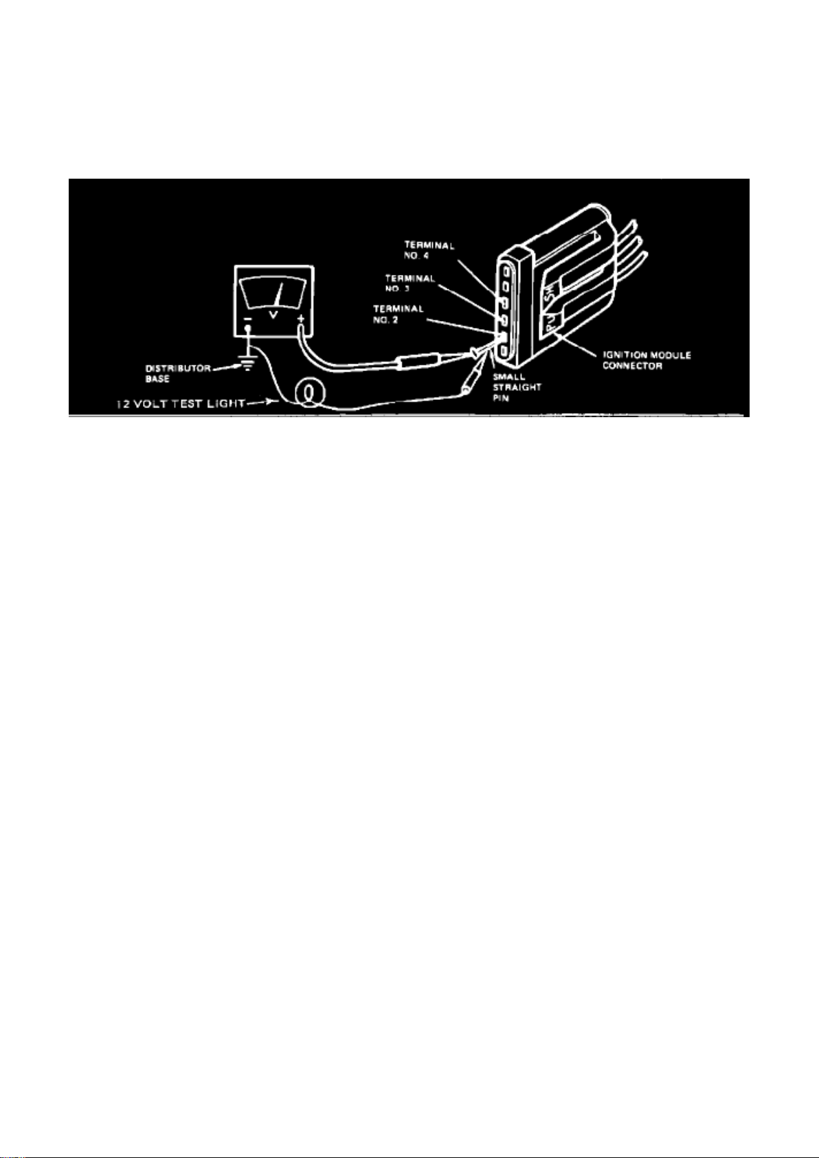
If the TFI module fails and causes a short to ground, the primary winding of the ignition coil can be
damaged. The TFI diagnostic procedure published in the Shop Manual will not identify this
condition.
When servicing a weak or no spark condition, perform the following:
1. Check for spark using the procedures found in the Manual Information, Computerized Engine,
Quick Test Section, Test 1.
2. If there is no spark, test the coil primary resistance using Rotunda digital volt-ohmmeter
007-00001, as shown.
3. If the coil primary resistance is O.K., continue with the diagnostic procedure in Test 1.
4. If the coil primary resistance is not O.K., replace the coil and recheck for weak or no spark. If the
spark is now O.K., the problem is resolved.
5. If the spark is still NOT O.K., continue with normal diagnostic procedure in Test 1.
OTHER APPLICABLE ARTICLES: None WARRANTY STATUS: "INFORMATION ONLY"
Wiring Harness
Page 71

TFI-IV
Part 2
Test 5
TEST EQUIPMENT: VOM, STRAIGHT PIN
TEST PROCEDURE
1. Separate wiring harness connector from ignition module. Inspect for dirt, corrosion, and damage.
NOTE: PUSH connector tabs to separate.
2. Disconnect wire at S terminal of starter relay.
3. Attach negative (-) VOM, Rotunda Number 007-00001, lead to distributor base.
4. Measure battery voltage.
Page 72
Ford Mustang Workshop Manual (V8-302 5.0L VIN M 4-bbl HP (1983))
Ford Workshop Manuals > Relays and Modules > Relays and Modules - Powertrain Management > Relays and Modules Ignition System > Ignition Control Module > Component Information > Technical Service Bulletins > Customer Interest: >
86220 > Jan > 86 > Ignition System - Weak/No Spark > Page 113
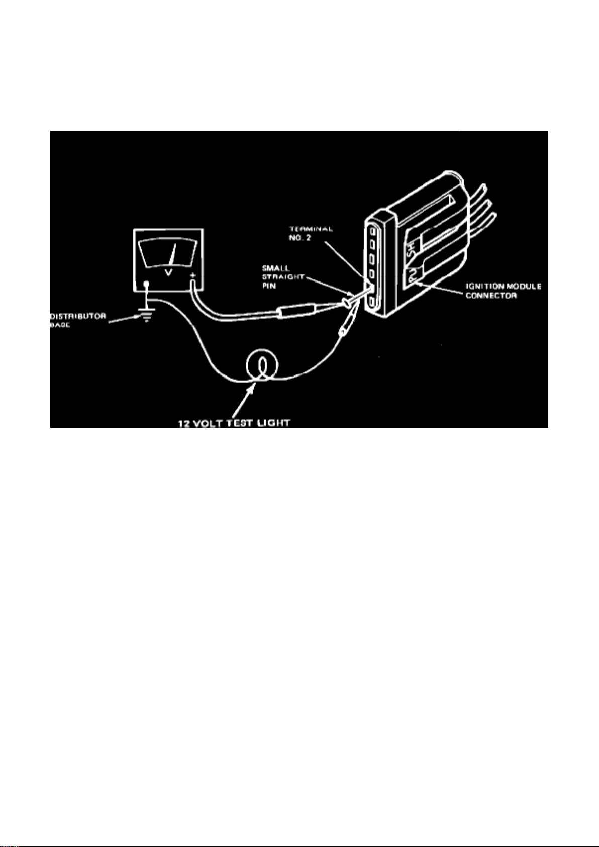
5. Following table below, measure connector terminal voltage by attaching VOM to small straight
pin inserted into connector terminal and turning ignition switch to position shown.
CAUTION: Do not allow straight pin to contact electrical ground.
CONNECTOR IGNITION SWITCH
TERMINAL WIRE/CIRCUIT TEST POSITION
#2 TO IGNITION RUN
COIL (-) TERMINAL
#3 RUN CIRCUIT RUN AND START
#4 START CIRCUIT START
6. Turn ignition switch to Off position.
7. Remove straight pin.
8. Reconnect wire to S terminal of starter relay.
TEST RESULT TEST RESOLUTION
90 percent of ^ Test result OK.
battery ^ Go to Part 2, Test 6.
Page 73

voltage minimum
Less than 90 ^ Inspect for faults in wiring
percent of harness and connectors.
battery ^ Refer to vehicle wiring
voltage diagram for appropriate
circuit.
^ Damaged or worn ignition switch, Refer to Shop Manual, Group 33.
Primary Circuit Continuity
TFI-IV
Part 2
Test 8
TEST EQUIPMENT: VOM, STRAIGHT PIN
TEST PROCEDURE
1. Separate wiring harness connector from ignition module. Inspect for dirt, corrosion, and damage.
NOTE: PUSH connector tabs to separate.
Page 74
Ford Mustang Workshop Manual (V8-302 5.0L VIN M 4-bbl HP (1983))
Ford Workshop Manuals > Relays and Modules > Relays and Modules - Powertrain Management > Relays and Modules Ignition System > Ignition Control Module > Component Information > Technical Service Bulletins > Customer Interest: >
86220 > Jan > 86 > Ignition System - Weak/No Spark > Page 114
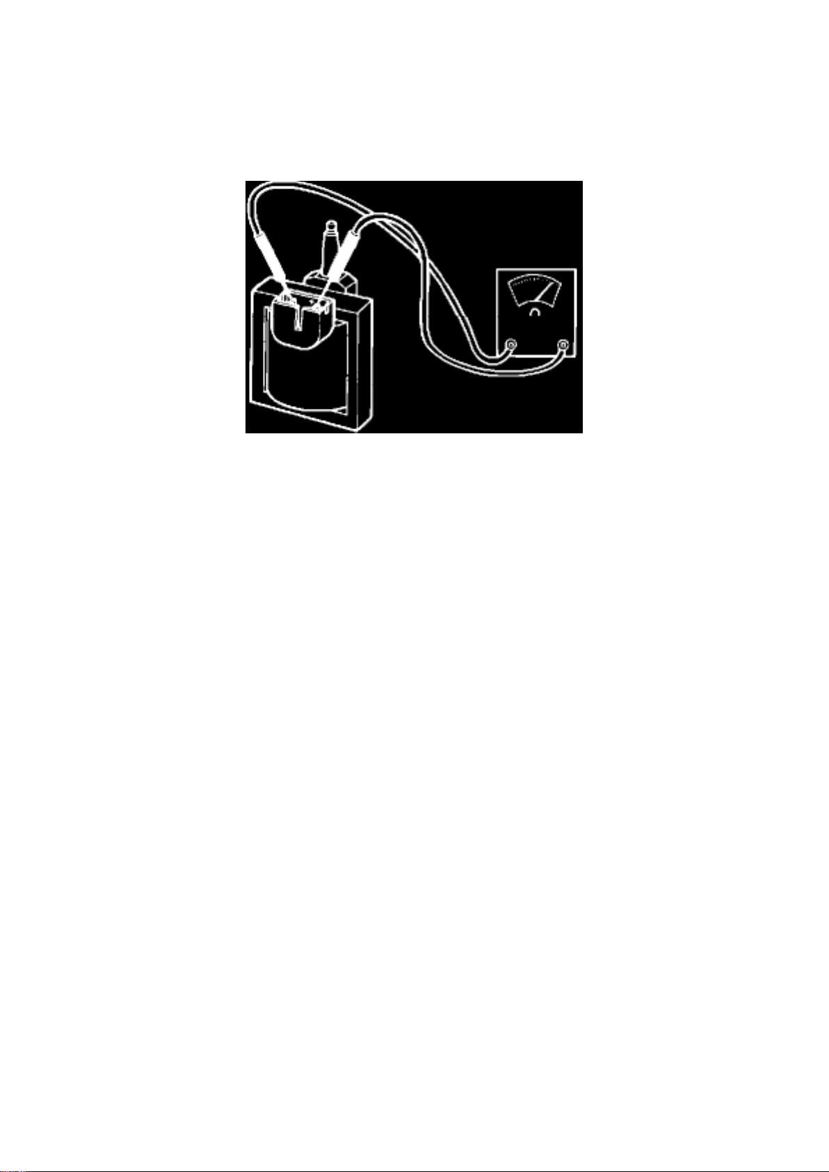
2. Attach negative (-) VOM, Rotunda Number 007-00001, lead to distributor base.
3. Measure battery voltage.
4. Attach VOM to small straight pin inserted into connector terminal No. 2.
CAUTION: Do not allow straight pin to contact electrical ground.
5. Turn ignition switch to Run position and measure terminal No. 2 voltage.
6. Turn ignition switch to Off position.
7. Remove straight pin.
TEST RESULT TEST RESOLUTION
90 percent of ^ Go to Part 2, Test 5.
battery voltage minimum
Less than 90 ^ Go to Part 2, Test 9.
percent of battery voltage
Ignition Coil Primary Resistance
TFI-IV
Part 2
Test 3
TEST EQUIPMENT: VOM
TEST PROCEDURE
1. Turn ignition switch to Off.
2. Disconnect ignition coil connector. Inspect for dirt, corrosion, and damage.
Page 75

3. Measure resistance from positive (+) to negative (-) terminal of ignition coil, using Rotunda digital
volt-ohmmeter 007-00001.
TEST RESULT TEST RESOLUTION
0.3 to 1.0 ^ Test result OK.
ohm ^ Go to Test 4.
Less than ^ Replace ignition coil.
0.3 ohm or greater than 1.0 ohm
Page 76

Ford Mustang Workshop Manual (V8-302 5.0L VIN M 4-bbl HP (1983))
Ford Workshop Manuals > Relays and Modules > Relays and Modules - Powertrain Management > Relays and Modules Ignition System > Ignition Control Module > Component Information > Technical Service Bulletins > Customer Interest: >
832313 > Nov > 83 > TFI Module - No Start/Intermittent Run
Page 77

Ignition Control Module: Customer Interest TFI Module - No Start/Intermittent Run
Page 78

Article No. 83-23-13
NO START - INTERMITTENT RUN - ALL ENGINES WITH T.F.I.
FORD 1983 ESCORT, EXP, MUSTANG, T-BIRD; 1984 ESCORT, EXP, MUSTANG, TEMPO,
LTD, T-BIRD, CROWN VICTORIA
LINCOLN-MERCURY 1983 LYNX, LN7; 1984 CAPRI, TOPAZ, MARQUIS, GRAND MARQUIS,
LINCOLN, MARK, CONTINENTAL
LIGHT TRUCKS 1983 RANGER
CALIBRATIONS: All with T.F.I. (Thick Film Ignition)
No start or intermittent run conditions can be caused by plastic housing of the T.F.I. module
separating from the metal base plate.
Page 79

Ford Mustang Workshop Manual (V8-302 5.0L VIN M 4-bbl HP (1983))
Ford Workshop Manuals > Relays and Modules > Relays and Modules - Powertrain Management > Relays and Modules Ignition System > Ignition Control Module > Component Information > Technical Service Bulletins > Customer Interest: >
832313 > Nov > 83 > TFI Module - No Start/Intermittent Run > Page 119
Page 80
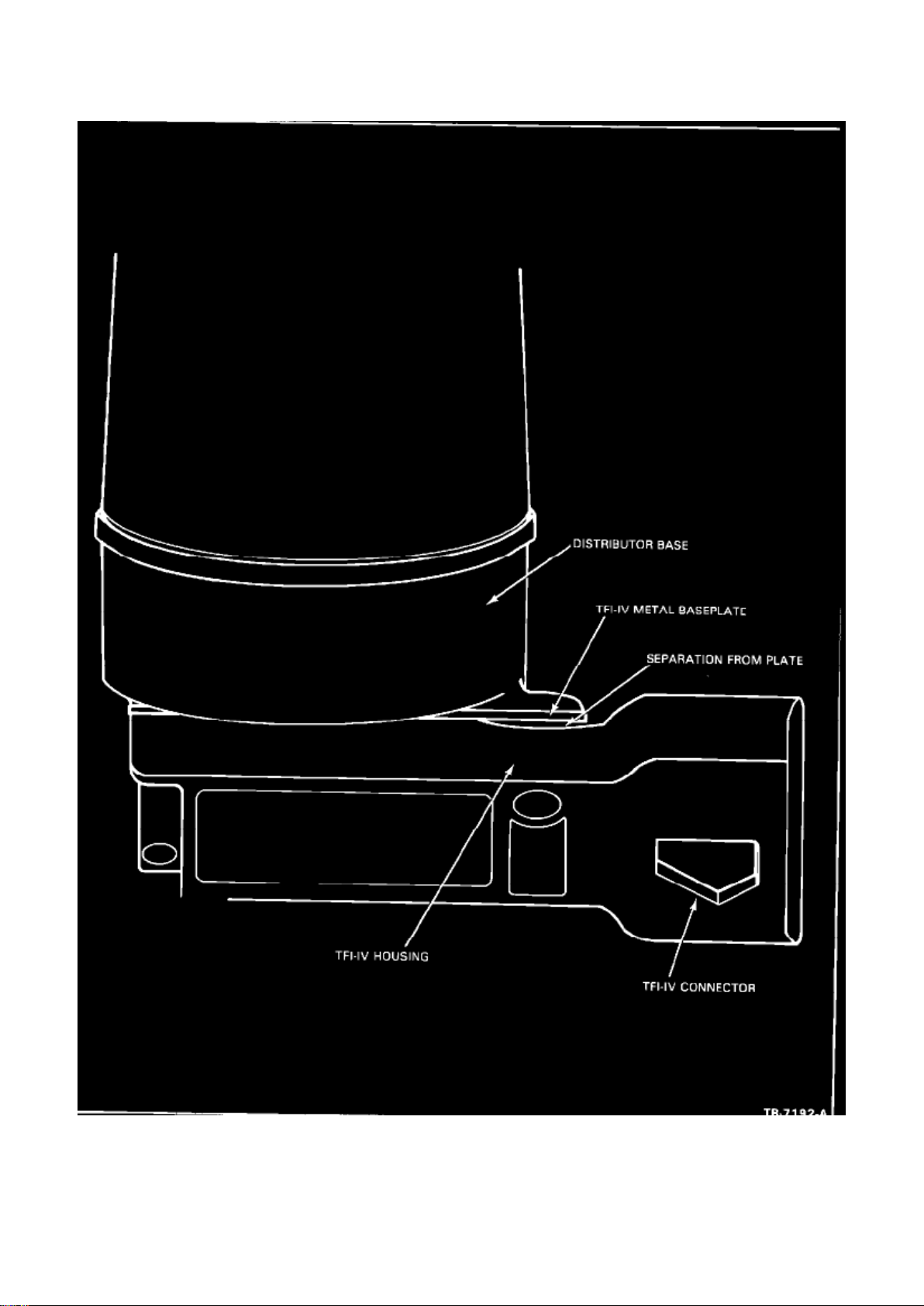
Figure 7
Page 81

For the above customer concern, visually inspect the T.F.I. ignition module to determine if the
plastic housing has partially separated from the metal base plate next to the connector (Figure 7). If
the module has separated replace it. Coat the metal base plate of the T.F.I. module with silicon
compound (D7AZ-19A331-A or equivalent), approximately 1/32 inch thick. Tighten the mounting
screws to 2.5-2.8 N-m of torque. This concern can be caused if the module is used as a handle for
adjusting or moving the distributor. PART NUMBER
PART NAME CLASS
D7AZ-19A331-A Silicon Compound A
OTHER APPLICABLE ARTICLES: None WARRANTY STATUS: Reimbursable within the
provisions of the Warranty and Policy Manual.
Page 82

Ford Mustang Workshop Manual (V8-302 5.0L VIN M 4-bbl HP (1983))
Ford Workshop Manuals > Relays and Modules > Relays and Modules - Powertrain Management > Relays and Modules Ignition System > Ignition Control Module > Component Information > Technical Service Bulletins > Customer Interest: >
832313 > Nov > 83 > TFI Module - No Start/Intermittent Run > Page 120
Page 83

OPERATION/TIME: Refer to the Labor Time Standards Manual for applicable operation and time.
DLR. CODING: Basic Part No. 12A297 Code: 02
Page 84
Ford Mustang Workshop Manual (V8-302 5.0L VIN M 4-bbl HP (1983))
Ford Workshop Manuals > Relays and Modules > Relays and Modules - Powertrain Management > Relays and Modules Ignition System > Ignition Control Module > Component Information > Technical Service Bulletins > All Technical Service
Bulletins for Ignition Control Module: > 9015 > Jan > 90 > Duraspark II Ignition - Revised Applications
Ignition Control Module: All Technical Service Bulletins Duraspark II Ignition - Revised Applications
HARD START - ALL WITH DURASPARK II IGNITION, MODULES - REVISED APPLICATIONS
Article No. 90-1-5
FORD: 1976-83 THUNDERBIRD 1976-86 MUSTANG 1978-83 FAIRMONT 1978-86 CROWN
VICTORIA 1981-82 ESCORT, EXP 1983-86 LTD 1984-87 TEMPO
Page 85

LINCOLN-MERCURY: 1976-83 COUGAR 1976-86 CAPRI 1978-83 ZEPHYR 1978-86 GRAND
MARQUIS 1981-82 LN7, LYNX 1982-83 TOWN CAR 1983 CONTINENTAL 1983-86 MARQUIS
1984-87 TOPAZ
LIGHT TRUCK: 1973-78 BRONCO 1976-83 ECONOLINE, F-150-350 SERIES 1983-88 RANGER
MEDIUM/HEAVY TRUCK: 1979-89 C SERIES, F & B SERIES, L SERIES
Page 86
Ford Mustang Workshop Manual (V8-302 5.0L VIN M 4-bbl HP (1983))
Ford Workshop Manuals > Relays and Modules > Relays and Modules - Powertrain Management > Relays and Modules Ignition System > Ignition Control Module > Component Information > Technical Service Bulletins > All Technical Service
Bulletins for Ignition Control Module: > 9015 > Jan > 90 > Duraspark II Ignition - Revised Applications > Page 126
Page 87

This TSB article is being republished in its entirety to correct the Motorcraft part number for the
E9VZ-12A199-A Ignition Module.
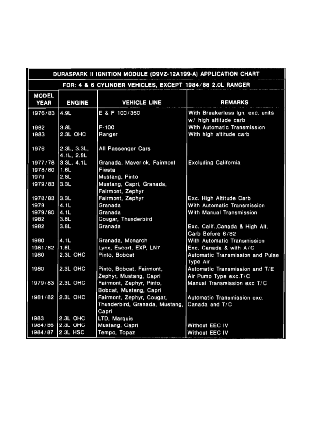
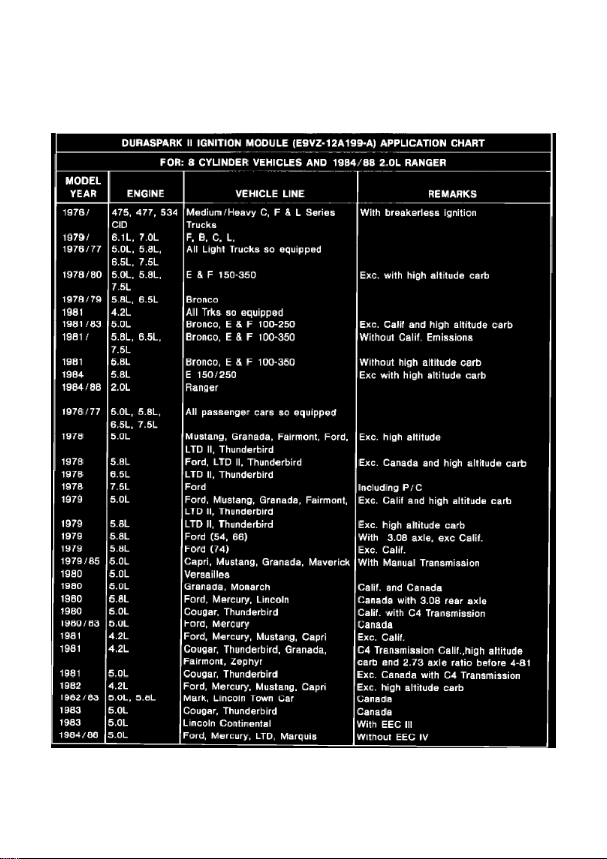
ISSUE: A hard starting condition may exist if the incorrect Duraspark II ignition module is used.
Revised Duraspark II ignition module assembly application charts are shown below.
ACTION: If service is required, refer to the following Duraspark II Ignition Module Assembly
Application Charts for correct parts usage. Although some earlier models such as the Fiesta,
Granada, Monarch, etc. are no longer carried in the TSB index, they are shown in the charts for
easy reference.
NOTE: IT'S IMPORTANT TO NOTE THAT DURASPARK II IGNITION MODULE (D9VZ-12AI99-A)
CAN NOT BE USED ON 1984-88 2.0L
RANGERS OR ON 1984-91 6.1L OR 7.0L, F, B, C, AND L MEDIUM/HEAVY TRUCKS.
PART NUMBER PART NAME
D9VZ-12A199-A Duraspark Ignition Module B
Assy.(Motorcraft No. DY 184C)
E9VZ-12A199-A Duraspark Ignition Module B
Page 88

Ford Mustang Workshop Manual (V8-302 5.0L VIN M 4-bbl HP (1983))
Ford Workshop Manuals > Relays and Modules > Relays and Modules - Powertrain Management > Relays and Modules Ignition System > Ignition Control Module > Component Information > Technical Service Bulletins > All Technical Service
Bulletins for Ignition Control Module: > 9015 > Jan > 90 > Duraspark II Ignition - Revised Applications > Page 127
Page 89

Assy.(Motorcraft No. DY 611)
Page 90

OTHER APPLICABLE ARTICLES: None SUPERSEDES:
89-19-3
WARRANTY STATUS: INFORMATION ONLY OASIS CODES:
610300
Page 91

Ford Mustang Workshop Manual (V8-302 5.0L VIN M 4-bbl HP (1983))
Ford Workshop Manuals > Relays and Modules > Relays and Modules - Powertrain Management > Relays and Modules Ignition System > Ignition Control Module > Component Information > Technical Service Bulletins > All Technical Service
Bulletins for Ignition Control Module: > 872110 > Oct > 87 > TFI Module/PIP Sensor - New Diagnostic Procedure
Page 92

Technical Service Bulletin # 872110 Date: 871021
Page 93

TFI Module/PIP Sensor - New Diagnostic Procedure
EEC IV - TFI MODULE AND PIP SENSOR - Article No.
NEW DIAGNOSTIC PROCEDURE 87-21-10
FORD: 1983-88 ESCORT/EXP, MUSTANG, THUNDERBIRD, FORD 1984-88 TEMPO 1986-88
TAURUS
LINCOLN-MERCURY: 1983 MARK VI
1983-86 CAPRI 1983-87 LYNX 1983-88 COUGAR, MERCURY, CONTINENTAL, LINCOLN TOWN
CAR 1984-88 TOPAZ, MARK VII 1986-88 SABLE
MERKUR: 1985-88 XR4Ti 1988 SCORPIO
LIGHT TRUCK: 1983-88 ALL LIGHT TRUCK LINES
ISSUE: A new diagnostic procedure for testing the TFI module and PIP sensor has been
developed. This new procedure allows the technician to take a direct path when testing the TFI
module and PIP sensor with the use of the new TFI IV diagnostic tester (Rotunda No. 105-00003).
ACTION: If service is required, use the diagnostic procedures on pages 29 through 60 of this TSB.
Insert these pages in the Engine/Emission Diagnosis Manual, Volume H, Section 15.
OTHER APPLICABLE ARTICLES: None WARRANTY STATUS: "INFORMATION ONLY"
Preliminary Checkout, Equipment & Notes
CHECKOUT
^ Visually inspect the engine compartment to ensure all vacuum hoses and spark plug wires are
properly routed and securely connected.
^ Examine all wiring harnesses and connectors for insulation damage, burned, overheated, loose
or broken conditions.
^ Check that the TFI module is securely fastened to the distributor base.
^ Be certain the battery is fully charged.
^ All accessories should be off during diagnosis.
EQUIPMENT
Obtain the following test equipment or an equivalent:
^ Spark Tester, Special Service Tool D81P-6666-A. See note.
^ Volt/Ohm Meter Rotunda 014-00407.
^ 12 Volt Test Light.
^ Small straight pin.
^ Remote Starter Switch.
^ TFI Ignition Tester, Rotunda 105-00002.
NOTES
Page 94

^ A spark plug with a broken side electrode is not sufficient to check for spark and may lead to
incorrect results.
^ When instructed to inspect a wiring harness, both a visual inspection and a continuity test should
be performed.
^ When making measurements on a wiring harness or connector, it is good practice to wiggle the
wires while measuring.
^ References to pin-in-line connector apply to a shorting bar type connector used to set base
timing.
^ This procedure is intended to identify faulty components or wiring while the fault is present. If the
complaint is of an intermittent condition, refer to Intermittent Diagnosis.
Page 95

Ford Mustang Workshop Manual (V8-302 5.0L VIN M 4-bbl HP (1983))
Ford Workshop Manuals > Relays and Modules > Relays and Modules - Powertrain Management > Relays and Modules Ignition System > Ignition Control Module > Component Information > Technical Service Bulletins > All Technical Service
Bulletins for Ignition Control Module: > 872110 > Oct > 87 > TFI Module/PIP Sensor - New Diagnostic Procedure > Page
132
Page 96
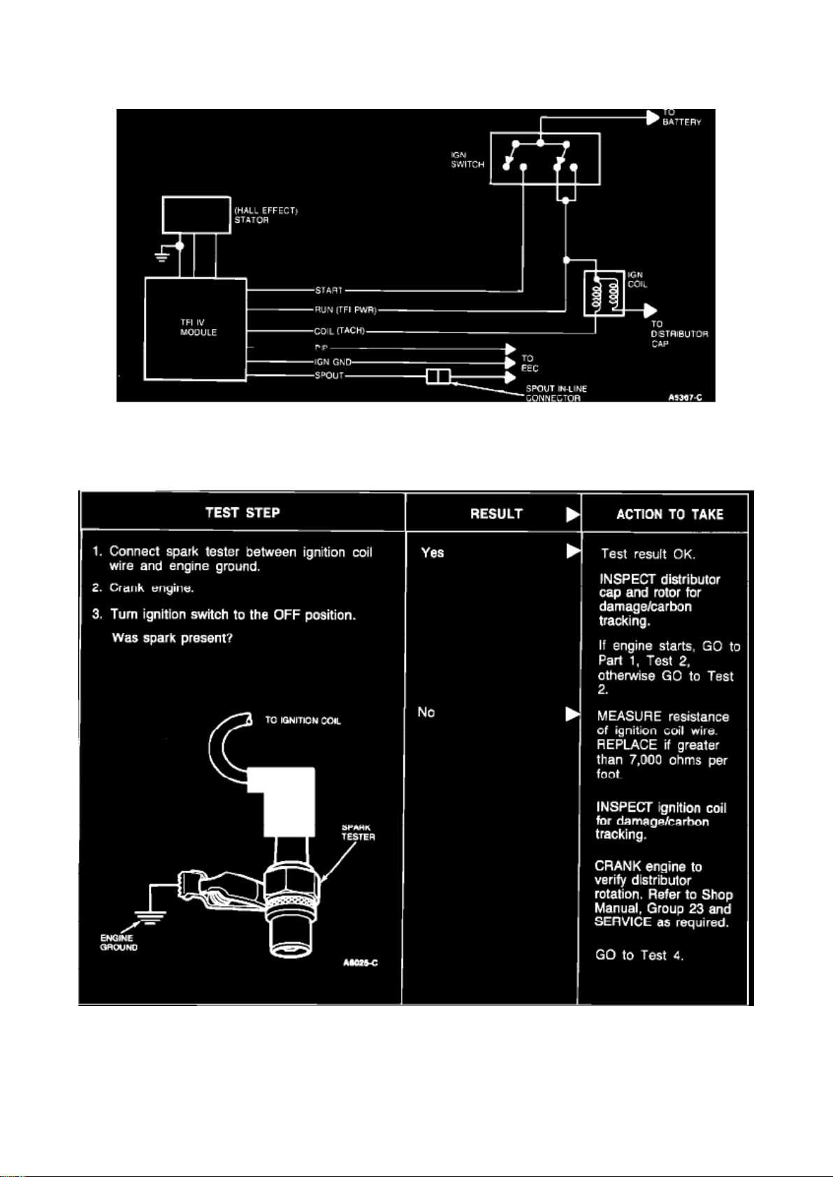
Functional Schematic
Page 97

TFI-IV
The TFI-IV system electrical schematic is shown below. For detailed information, refer to the
vehicle wiring diagram.
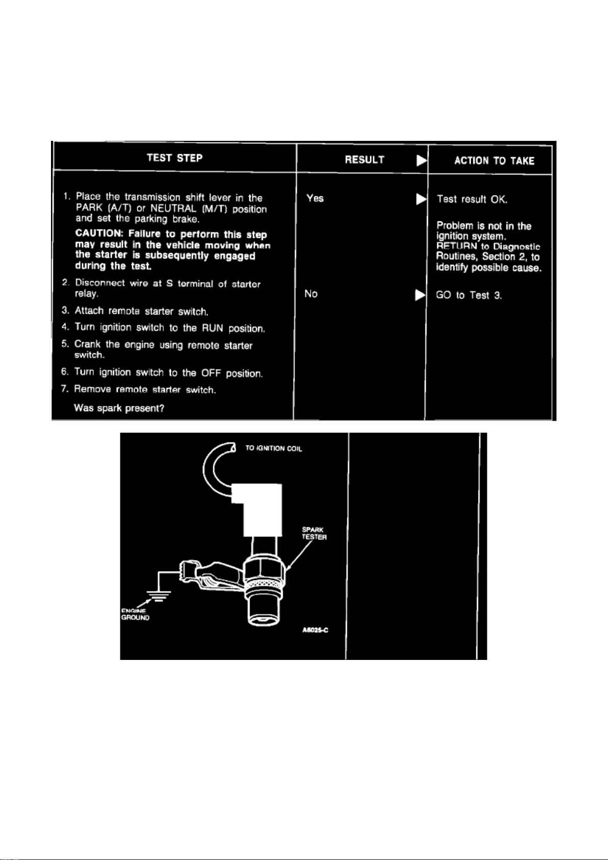
Ignition Coil Secondary Voltage (Crank Mode)
TFI-IV Part 2
Test 1 & 2
Page 98
Ford Mustang Workshop Manual (V8-302 5.0L VIN M 4-bbl HP (1983))
Ford Workshop Manuals > Relays and Modules > Relays and Modules - Powertrain Management > Relays and Modules Ignition System > Ignition Control Module > Component Information > Technical Service Bulletins > All Technical Service
Bulletins for Ignition Control Module: > 872110 > Oct > 87 > TFI Module/PIP Sensor - New Diagnostic Procedure > Page
133
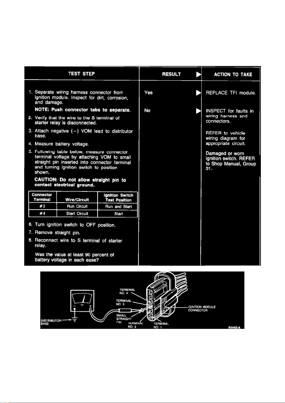
Ignition Coil Secondary Voltage
(Run Mode) TFI-IV Part 2
Test 2
Wiring Harness
Page 99
Ford Mustang Workshop Manual (V8-302 5.0L VIN M 4-bbl HP (1983))
Ford Workshop Manuals > Relays and Modules > Relays and Modules - Powertrain Management > Relays and Modules Ignition System > Ignition Control Module > Component Information > Technical Service Bulletins > All Technical Service
Bulletins for Ignition Control Module: > 872110 > Oct > 87 > TFI Module/PIP Sensor - New Diagnostic Procedure > Page
134
TFI-IV Part 2
Test 3
Stator - TFI
Page 100

Ford Mustang Workshop Manual (V8-302 5.0L VIN M 4-bbl HP (1983))
Ford Workshop Manuals > Relays and Modules > Relays and Modules - Powertrain Management > Relays and Modules Ignition System > Ignition Control Module > Component Information > Technical Service Bulletins > All Technical Service
Bulletins for Ignition Control Module: > 872110 > Oct > 87 > TFI Module/PIP Sensor - New Diagnostic Procedure > Page
135
 Loading...