

Page 1

Factory Workshop Manual
Ford
Mustang
V8-4.6L DOHC (1996)
Anonymous
1st January 2018
Make
Model
Engine and year
This manual was submitted by
Date
Page 2
Ford Mustang Workshop Manual (V8-4.6L DOHC (1996))
Ford Workshop Manuals > Relays and Modules > Relays and Modules - Accessories and Optional Equipment > Alarm
Module, (Vehicle Antitheft) > Component Information > Locations > Anti-Theft Control Module
Page 3

Alarm Module: Locations Anti-Theft Control Module
Convertible
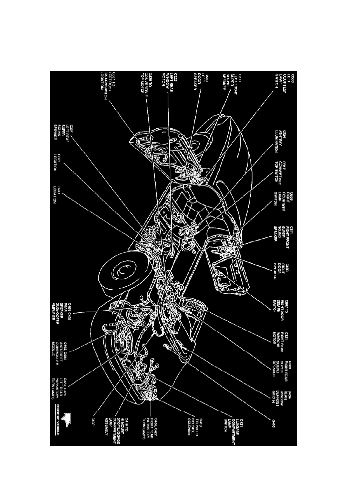
Full-body View (Convertible)
The Anti-Theft Controller Module is located at the LH rear of the trunk, behind trim panel.
Coupe
Page 4
Ford Mustang Workshop Manual (V8-4.6L DOHC (1996))
Ford Workshop Manuals > Relays and Modules > Relays and Modules - Accessories and Optional Equipment > Alarm
Module, (Vehicle Antitheft) > Component Information > Locations > Anti-Theft Control Module > Page 8
Page 5

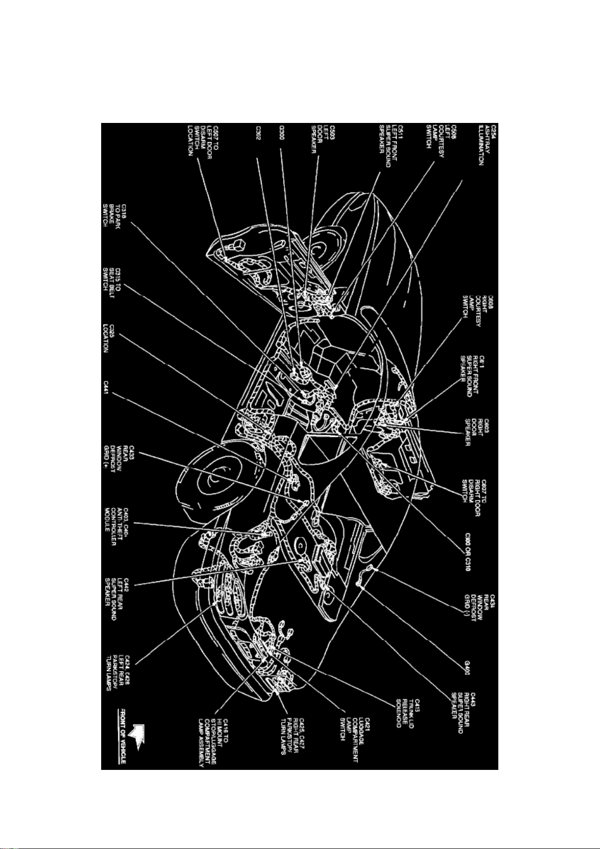
Full-body View (Coupe)
The Anti-Theft Controller Module is located at the LH rear of the trunk, behind trim panel.
Page 6
Ford Mustang Workshop Manual (V8-4.6L DOHC (1996))
Ford Workshop Manuals > Relays and Modules > Relays and Modules - Accessories and Optional Equipment > Alarm
Module, (Vehicle Antitheft) > Component Information > Locations > Anti-Theft Control Module > Page 9
Page 7

Alarm Module: Locations Passive Anti-Theft System Module
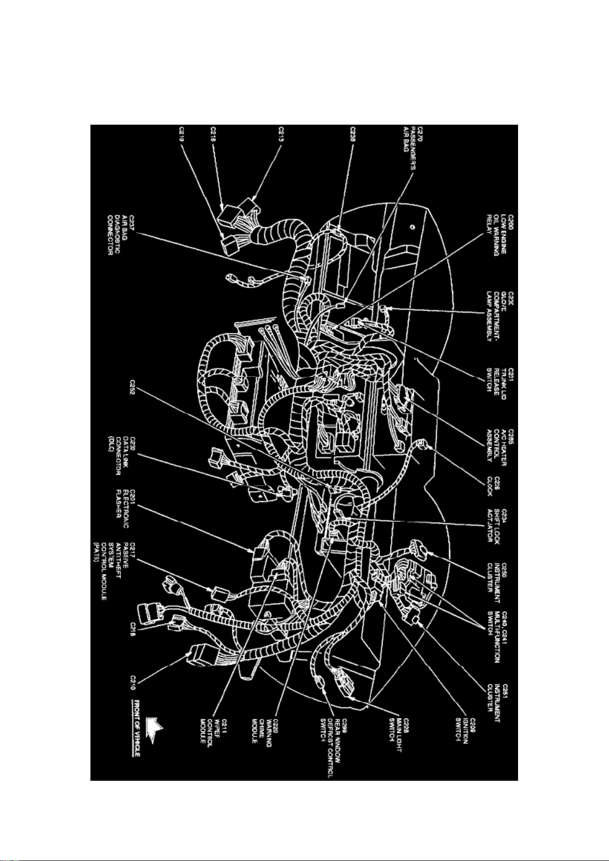
Instrument Panel View
Passive Anti-Theft System Module is located in instrument panel near wiper control module.
Page 8
Ford Mustang Workshop Manual (V8-4.6L DOHC (1996))
Ford Workshop Manuals > Relays and Modules > Relays and Modules - Accessories and Optional Equipment > Alarm
Module, (Vehicle Antitheft) > Component Information > Diagrams > Anti-Theft Controller Module
Alarm Module: Diagrams Anti-Theft Controller Module
Page 9

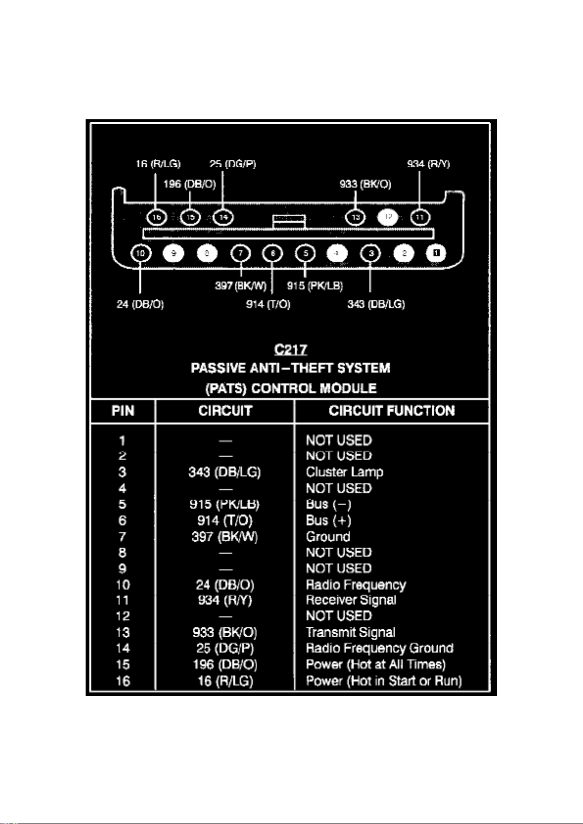
Passive Anti-Theft System Control Module
Page 10
Ford Mustang Workshop Manual (V8-4.6L DOHC (1996))
Ford Workshop Manuals > Relays and Modules > Relays and Modules - Accessories and Optional Equipment > Alarm
Module, (Vehicle Antitheft) > Component Information > Diagrams > Anti-Theft Controller Module > Page 12
Page 11

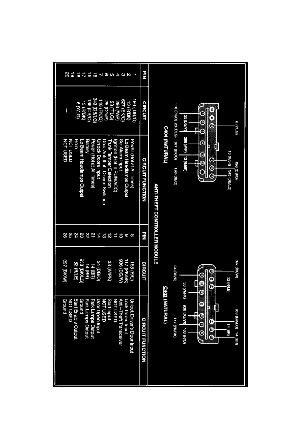
Anti-Theft Controller Module
Page 12
Ford Mustang Workshop Manual (V8-4.6L DOHC (1996))
Ford Workshop Manuals > Relays and Modules > Relays and Modules - Accessories and Optional Equipment > Alarm
Module, (Vehicle Antitheft) > Component Information > Diagrams > Anti-Theft Controller Module > Page 13
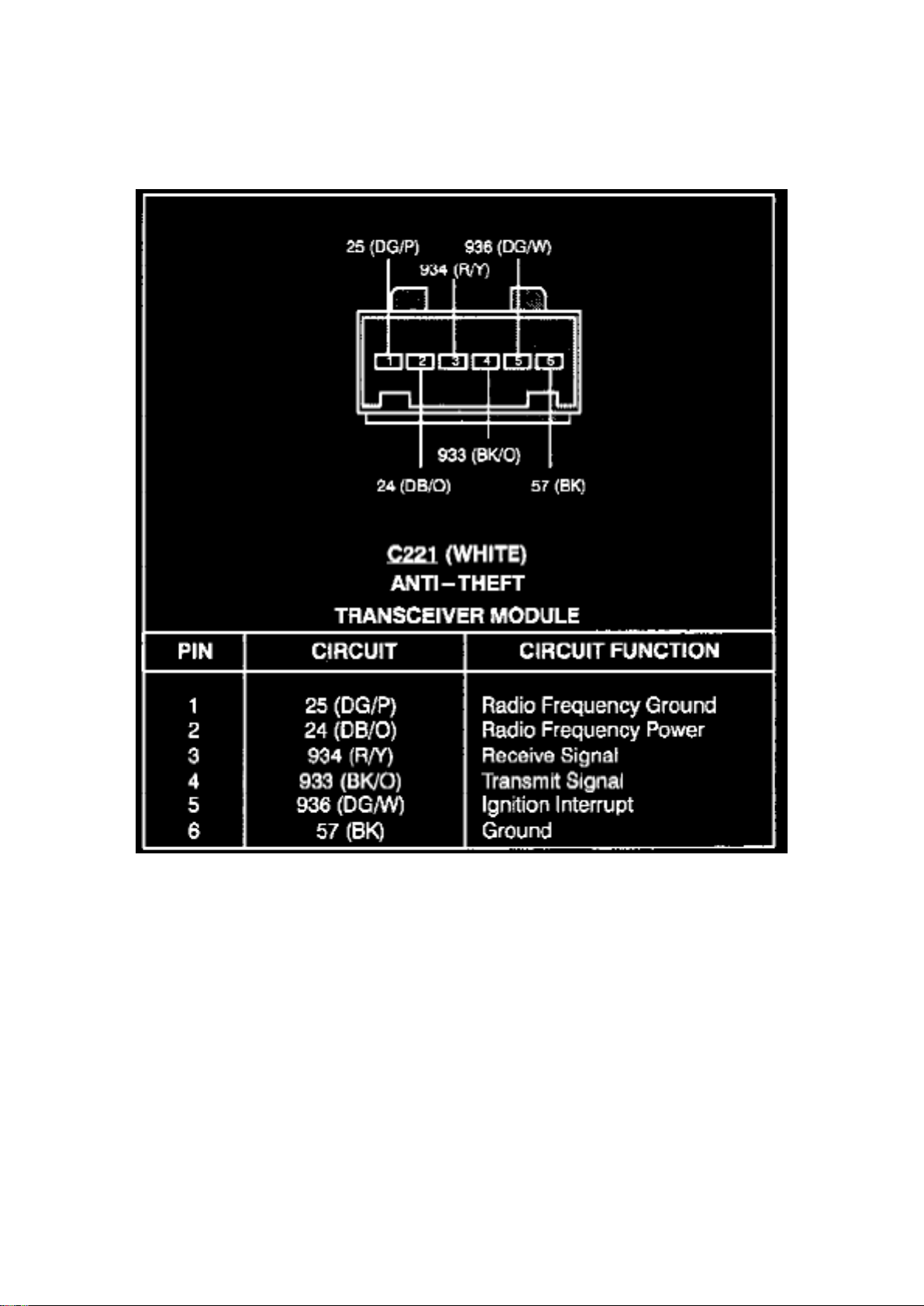
Transceiver Module
Page 13
Ford Mustang Workshop Manual (V8-4.6L DOHC (1996))
Ford Workshop Manuals > Relays and Modules > Relays and Modules - Accessories and Optional Equipment > Keyless
Entry Module > Component Information > Locations > Convertible
Page 14

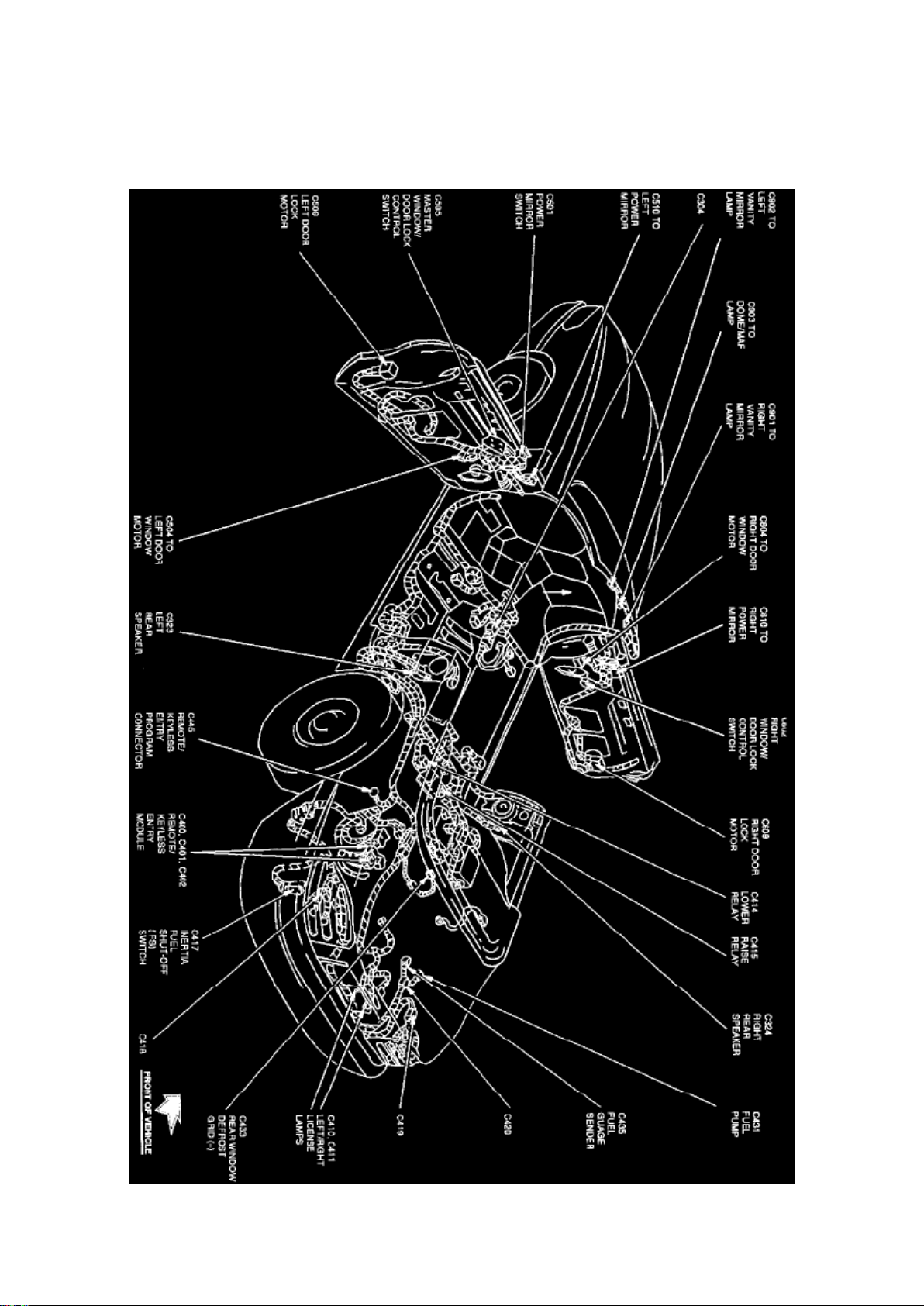
Keyless Entry Module: Locations Convertible
Full-body View (Convertible)
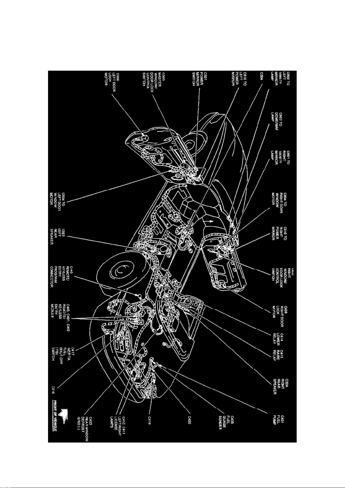
The Remote/Keyless Entry Module is located at the LH rear of trunk, behind side trim.
Page 15
Ford Mustang Workshop Manual (V8-4.6L DOHC (1996))
Ford Workshop Manuals > Relays and Modules > Relays and Modules - Accessories and Optional Equipment > Keyless
Entry Module > Component Information > Locations > Convertible > Page 18
Page 16

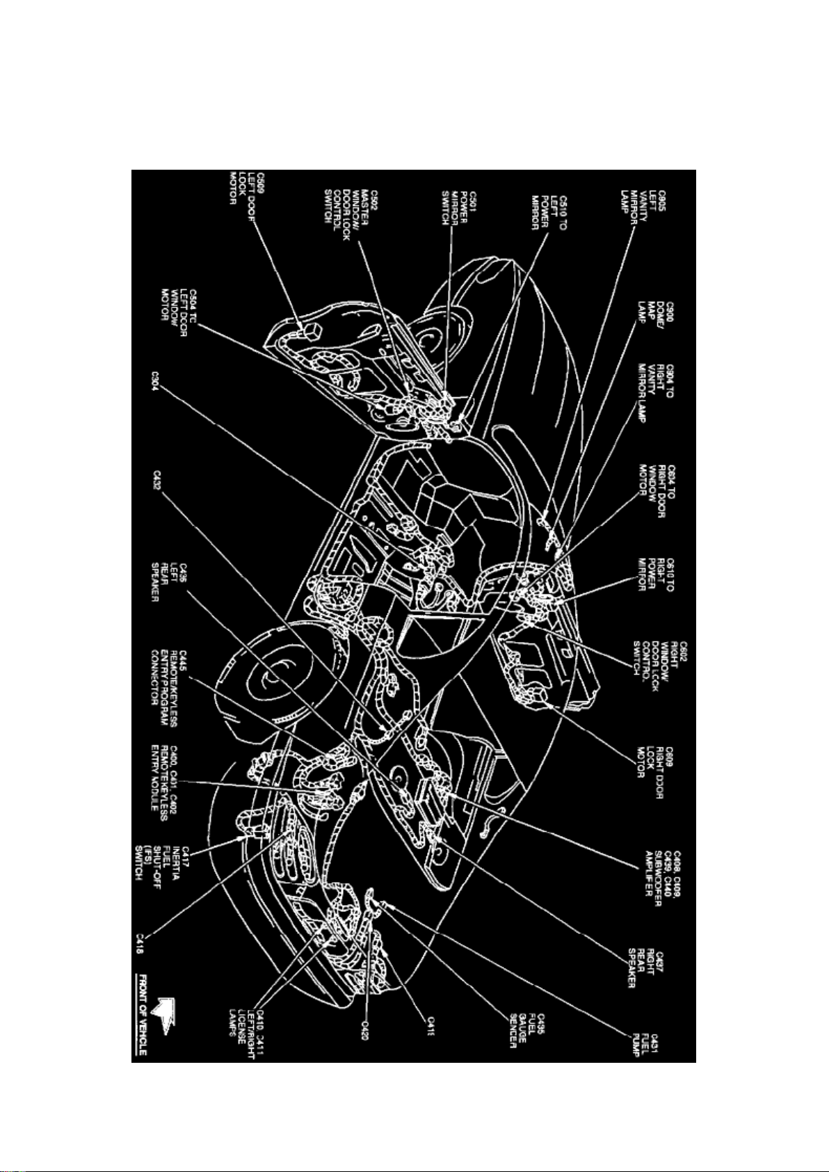
Keyless Entry Module: Locations Coupe
Full-Body View (Coupe)
The Remote/Keyless Entry Module is located at the LH rear of trunk, behind side trim.
Page 17
Ford Mustang Workshop Manual (V8-4.6L DOHC (1996))
Ford Workshop Manuals > Relays and Modules > Relays and Modules - Accessories and Optional Equipment > Keyless
Entry Module > Component Information > Locations > Page 19
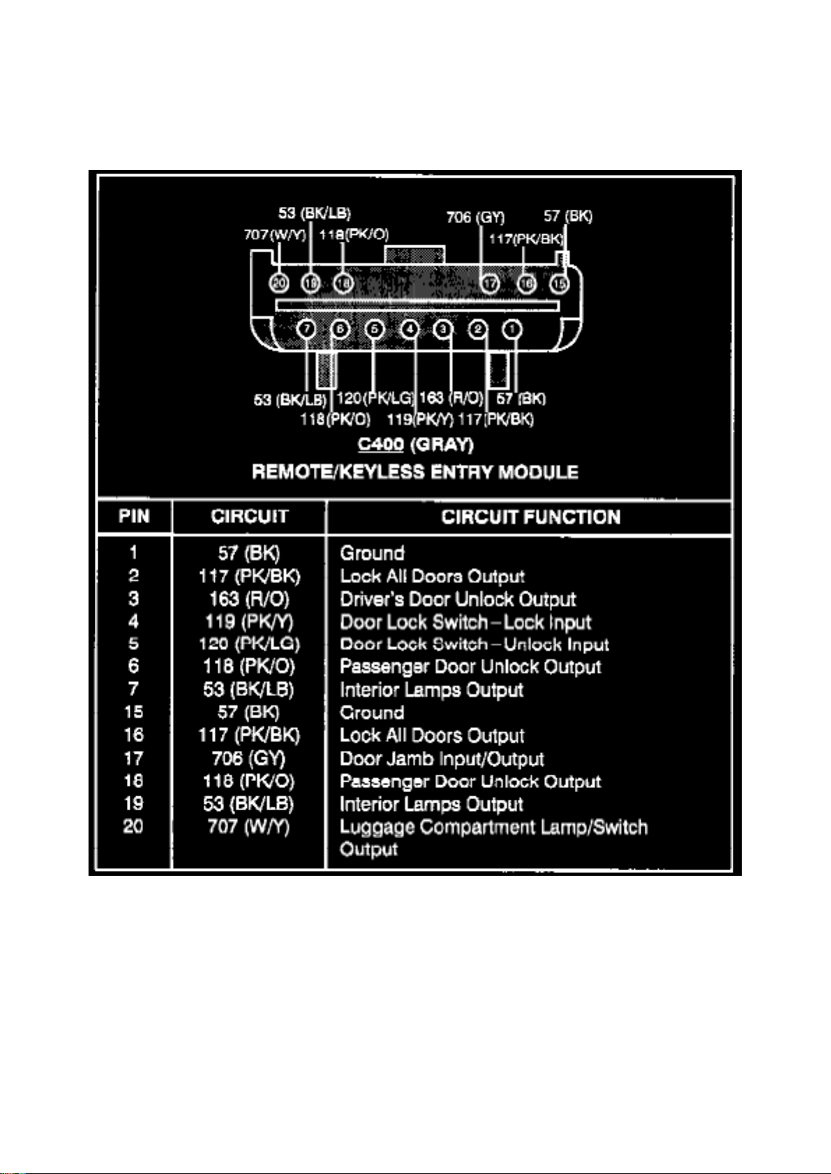
Keyless Entry Module: Diagrams
Remote/Keyless Entry Module (C400)
Page 18
Ford Mustang Workshop Manual (V8-4.6L DOHC (1996))
Ford Workshop Manuals > Relays and Modules > Relays and Modules - Accessories and Optional Equipment > Keyless
Entry Module > Component Information > Locations > Page 20
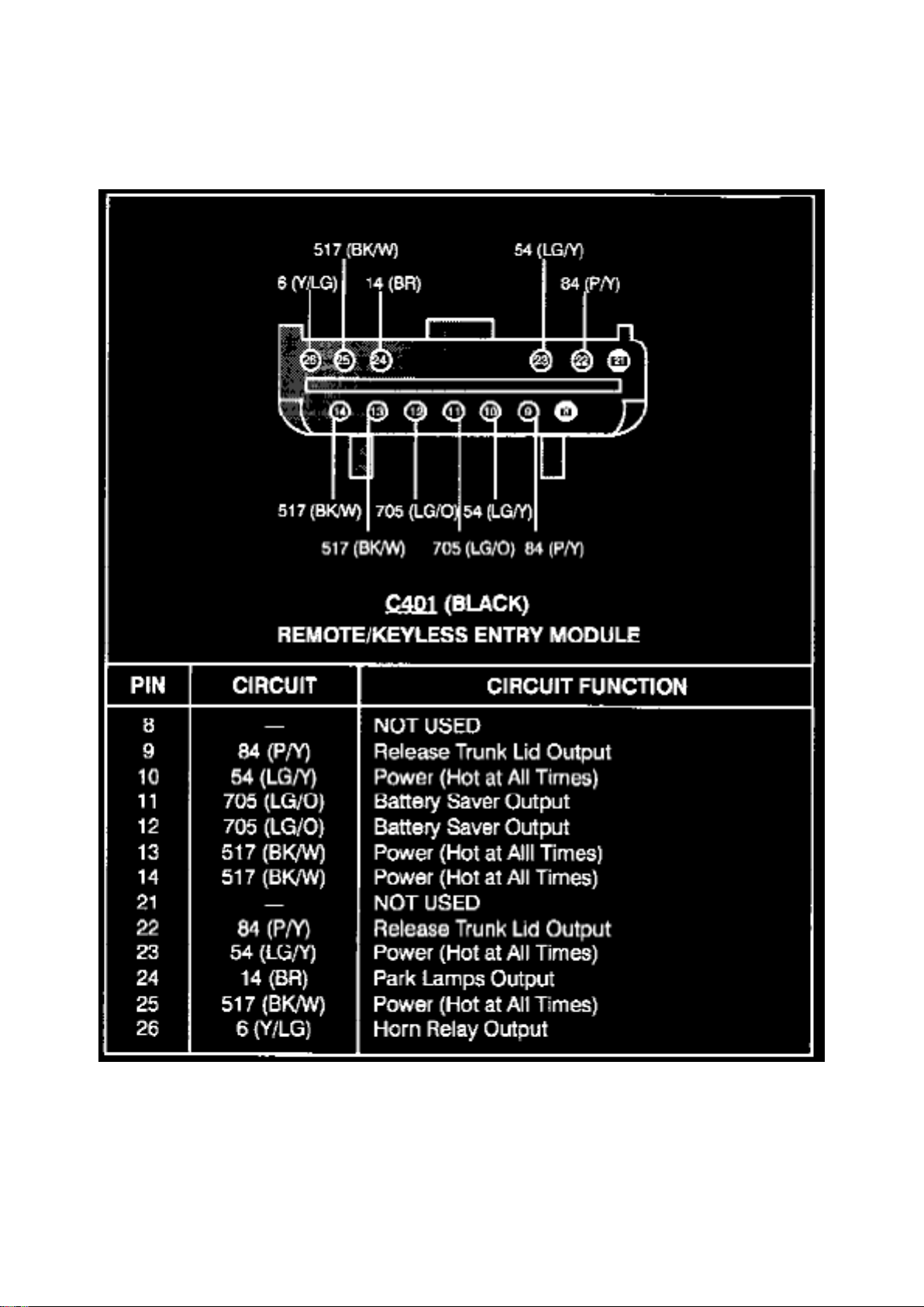
Remote/Keyless Entry Module (C401)
Page 19
Ford Mustang Workshop Manual (V8-4.6L DOHC (1996))
Ford Workshop Manuals > Relays and Modules > Relays and Modules - Accessories and Optional Equipment > Keyless
Entry Module > Component Information > Locations > Page 21
Page 20

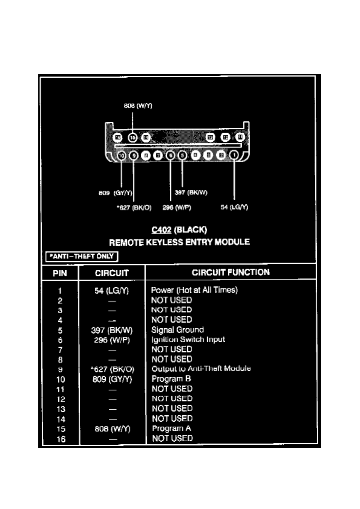
Remote/Keyless Entry Module (C402)
Page 21
Ford Mustang Workshop Manual (V8-4.6L DOHC (1996))
Ford Workshop Manuals > Relays and Modules > Relays and Modules - Body and Frame > Convertible Top Relay >
Component Information > Locations > Lower Relay
Page 22

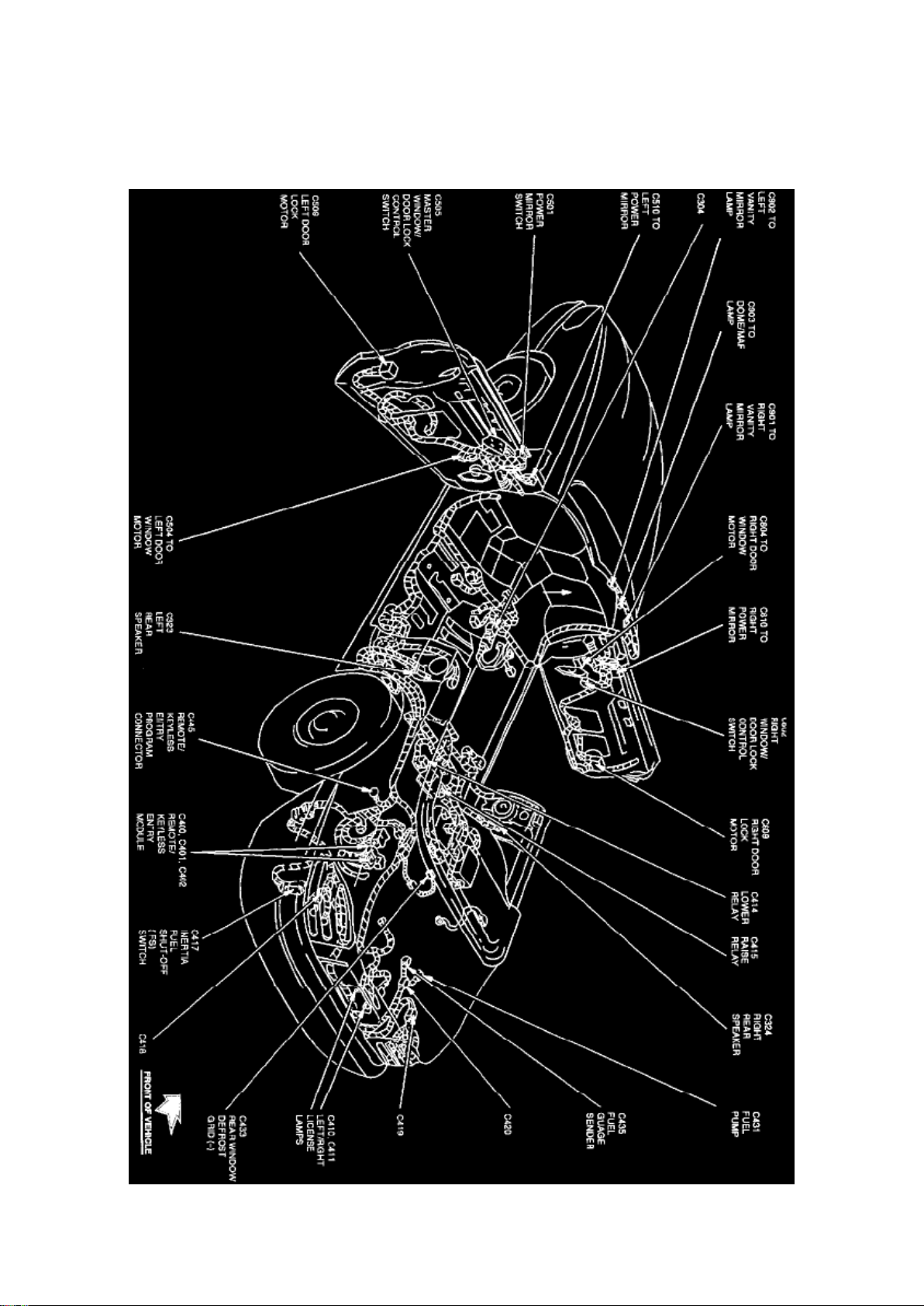
Convertible Top Relay: Locations Lower Relay
Full-body View (Convertible)
The Lower Relay is located behind rear seat, LH side of convertible top motor.
Page 23
Ford Mustang Workshop Manual (V8-4.6L DOHC (1996))
Ford Workshop Manuals > Relays and Modules > Relays and Modules - Body and Frame > Convertible Top Relay >
Component Information > Locations > Lower Relay > Page 27
Page 24

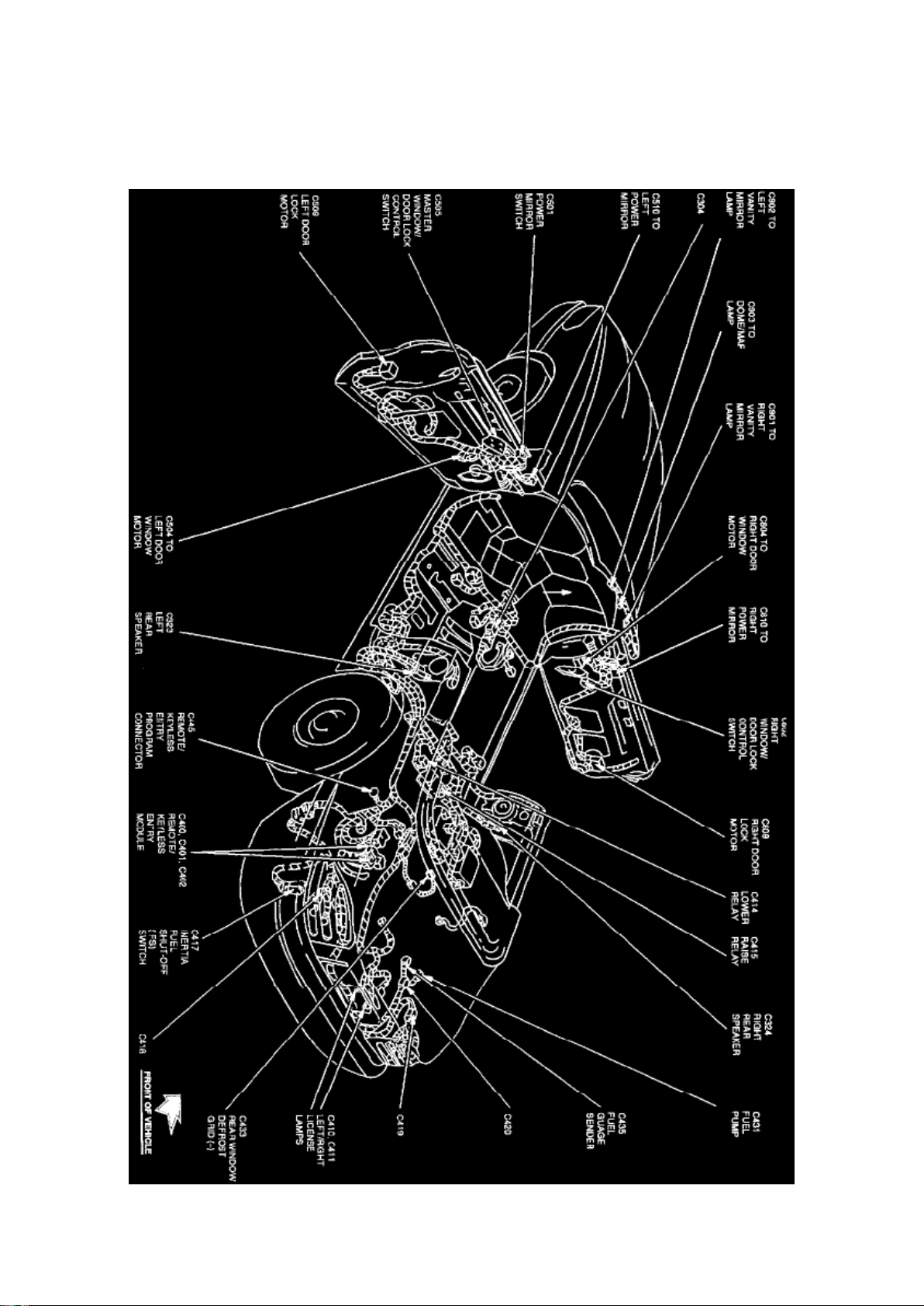
Convertible Top Relay: Locations Raise Relay
Full-body View (Convertible)
The Raise Relay is located behind top center of rear seat, LH side of convertible top motor.
Page 25
Ford Mustang Workshop Manual (V8-4.6L DOHC (1996))
Ford Workshop Manuals > Relays and Modules > Relays and Modules - Body and Frame > Convertible Top Relay >
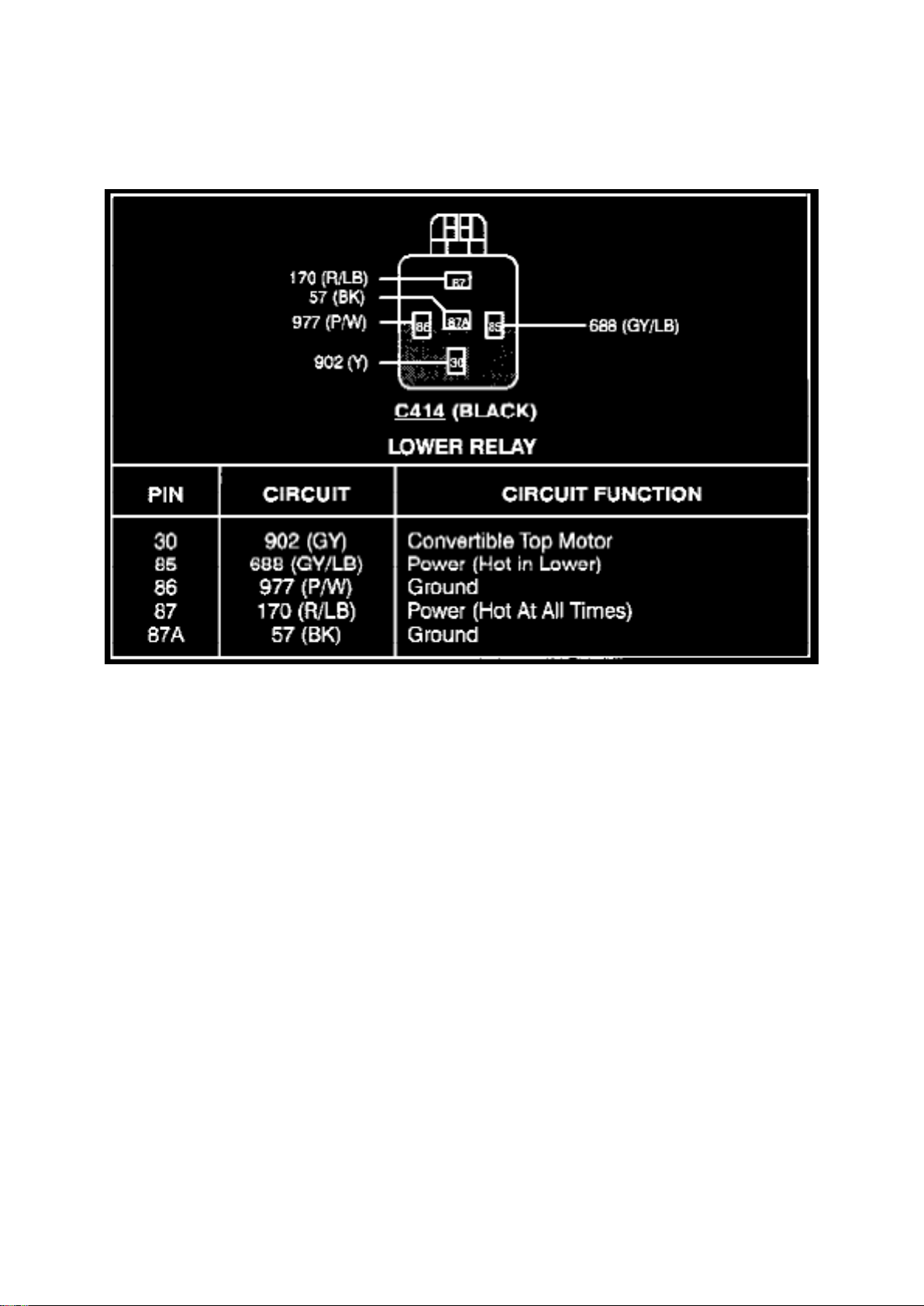
Component Information > Diagrams > Lower Relay
Lower Relay
Page 26
Ford Mustang Workshop Manual (V8-4.6L DOHC (1996))
Ford Workshop Manuals > Relays and Modules > Relays and Modules - Body and Frame > Convertible Top Relay >
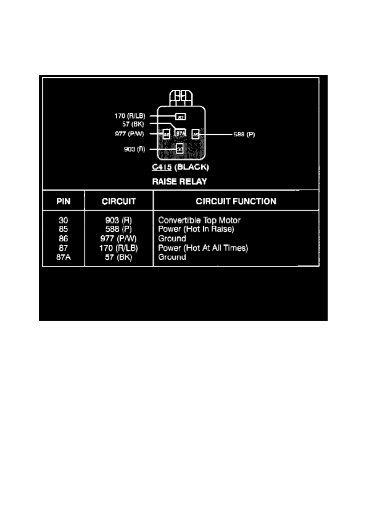
Component Information > Diagrams > Lower Relay > Page 30
Raise Relay
Page 27
Ford Mustang Workshop Manual (V8-4.6L DOHC (1996))
Ford Workshop Manuals > Relays and Modules > Relays and Modules - Body and Frame > Keyless Entry Module >
Component Information > Locations > Convertible
Page 28

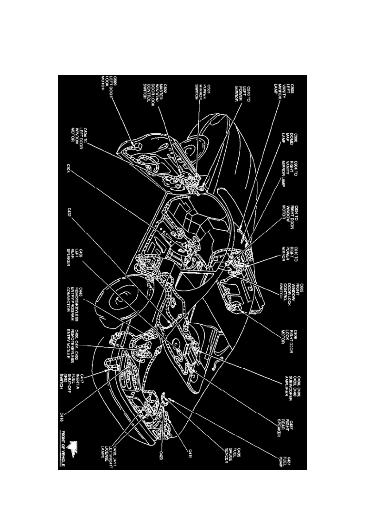
Keyless Entry Module: Locations Convertible
Full-body View (Convertible)
The Remote/Keyless Entry Module is located at the LH rear of trunk, behind side trim.
Page 29
Ford Mustang Workshop Manual (V8-4.6L DOHC (1996))
Ford Workshop Manuals > Relays and Modules > Relays and Modules - Body and Frame > Keyless Entry Module >
Component Information > Locations > Convertible > Page 35
Page 30

Keyless Entry Module: Locations Coupe
Full-Body View (Coupe)
The Remote/Keyless Entry Module is located at the LH rear of trunk, behind side trim.
Page 31
Ford Mustang Workshop Manual (V8-4.6L DOHC (1996))
Ford Workshop Manuals > Relays and Modules > Relays and Modules - Body and Frame > Keyless Entry Module >
Component Information > Locations > Page 36
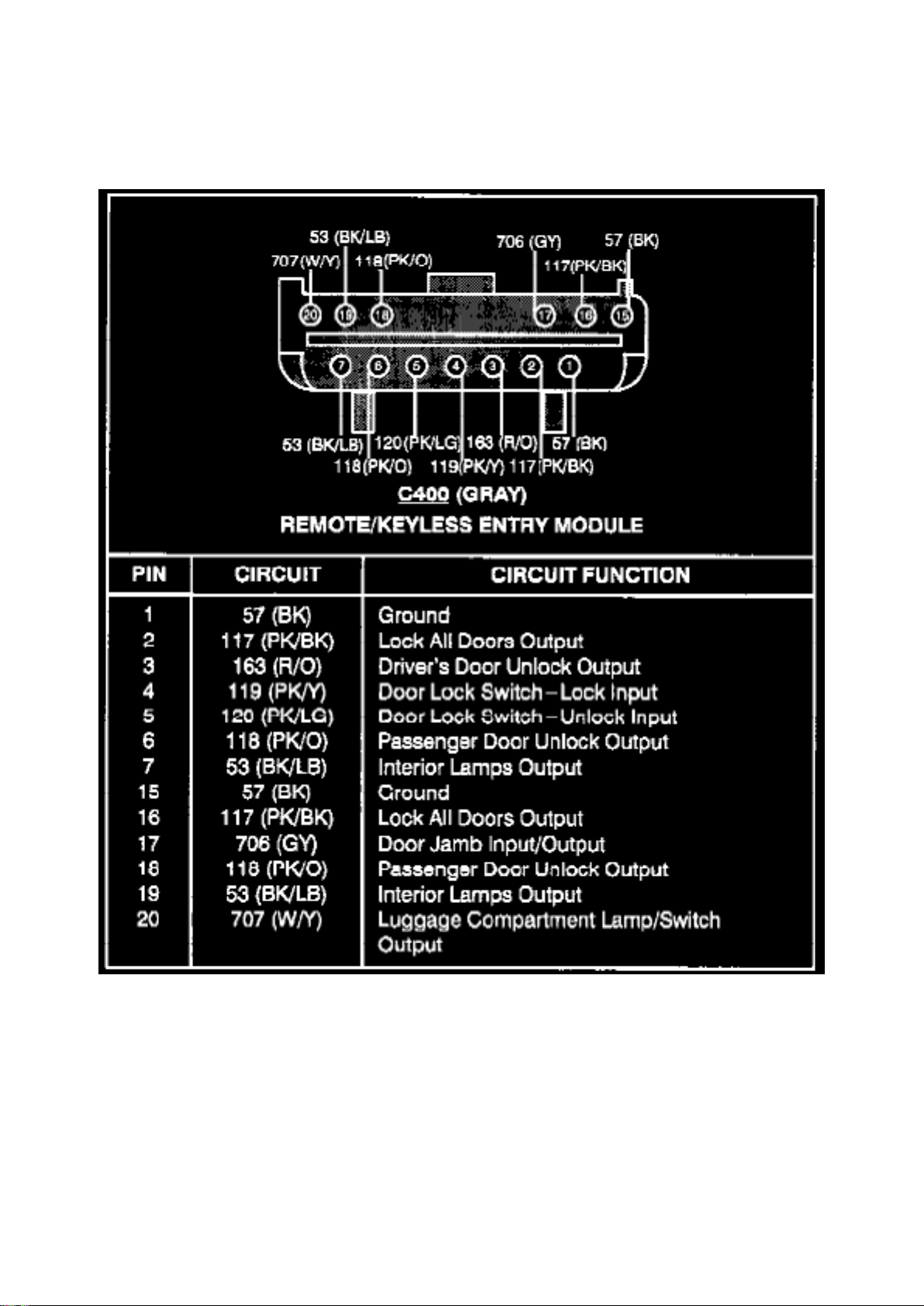
Keyless Entry Module: Diagrams
Remote/Keyless Entry Module (C400)
Page 32
Ford Mustang Workshop Manual (V8-4.6L DOHC (1996))
Ford Workshop Manuals > Relays and Modules > Relays and Modules - Body and Frame > Keyless Entry Module >
Component Information > Locations > Page 37
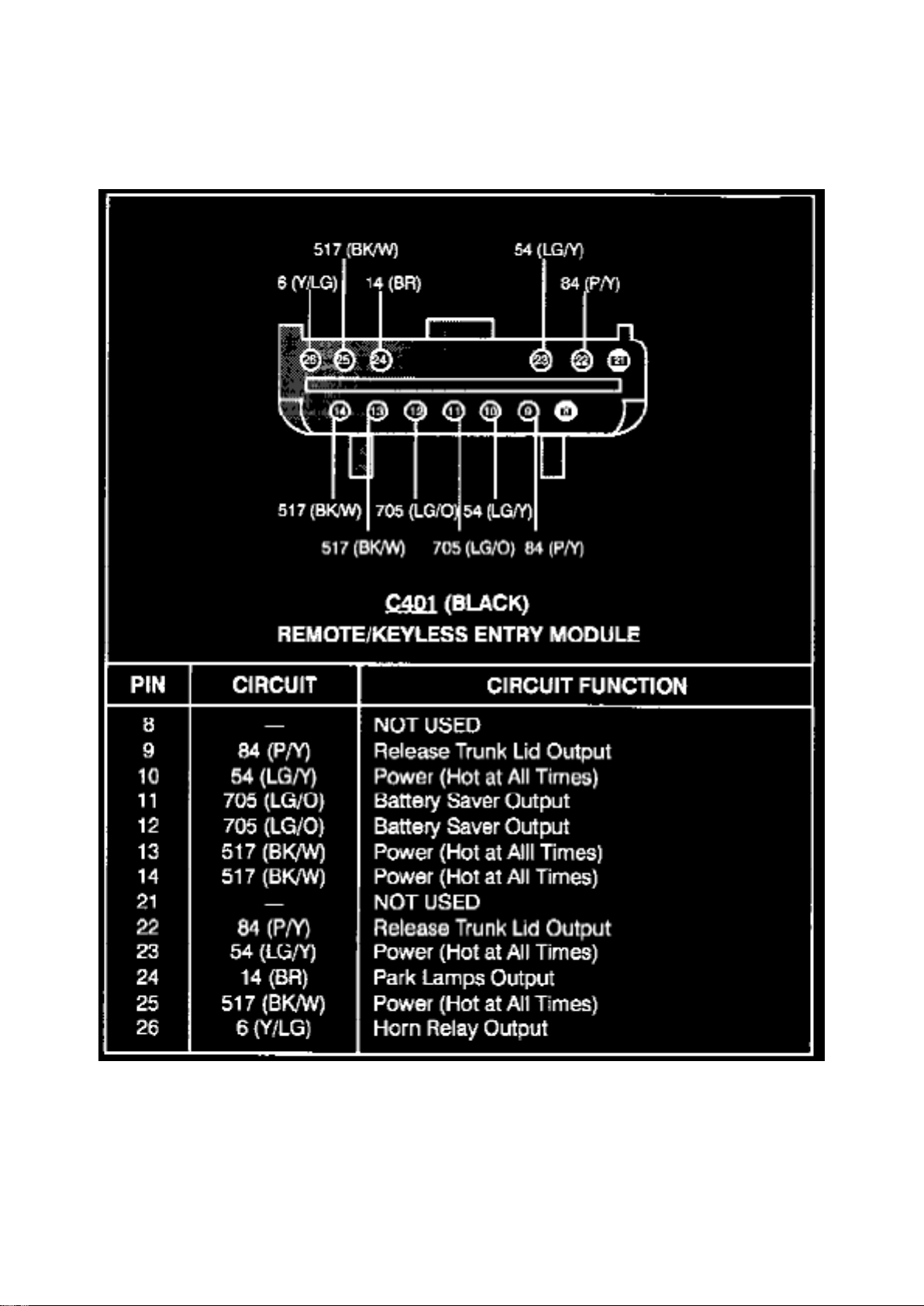
Remote/Keyless Entry Module (C401)
Page 33
Ford Mustang Workshop Manual (V8-4.6L DOHC (1996))
Ford Workshop Manuals > Relays and Modules > Relays and Modules - Body and Frame > Keyless Entry Module >
Component Information > Locations > Page 38
Page 34

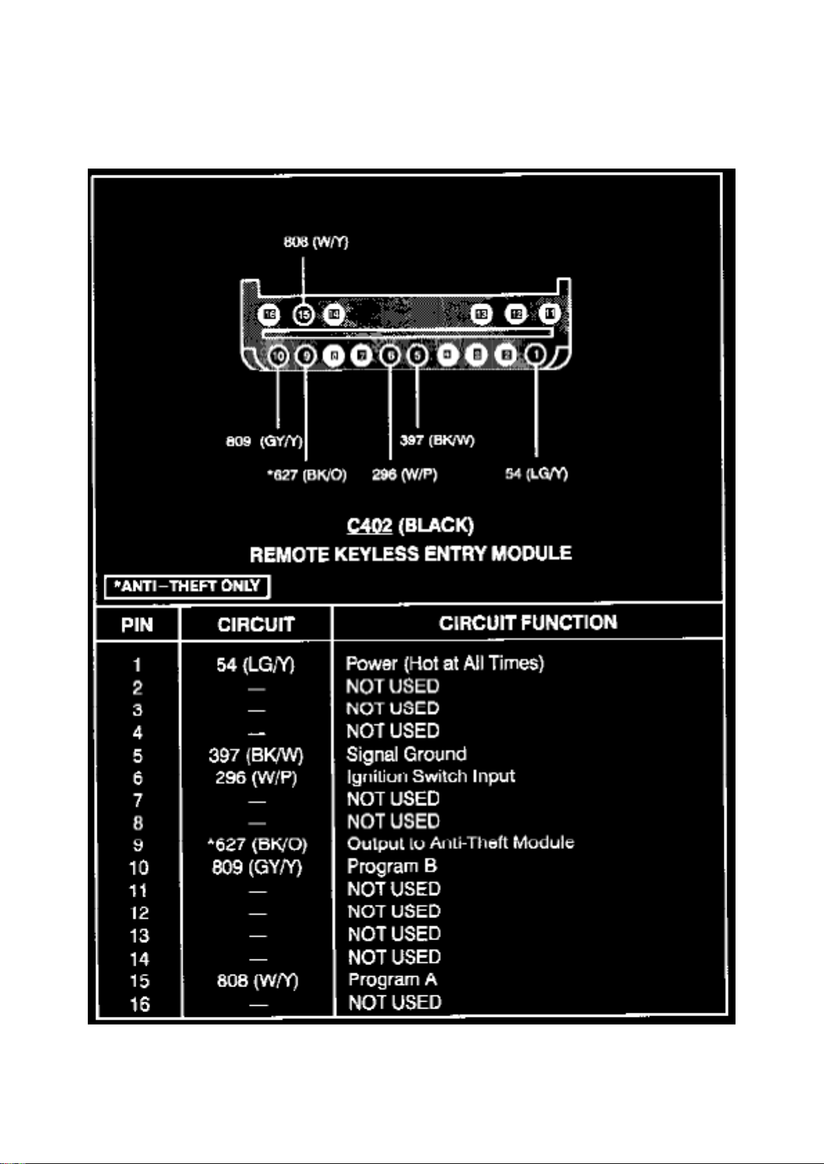
Remote/Keyless Entry Module (C402)
Page 35
Ford Mustang Workshop Manual (V8-4.6L DOHC (1996))
Ford Workshop Manuals > Relays and Modules > Relays and Modules - Brakes and Traction Control > Electronic Brake
Control Module > Component Information > Locations
Page 36

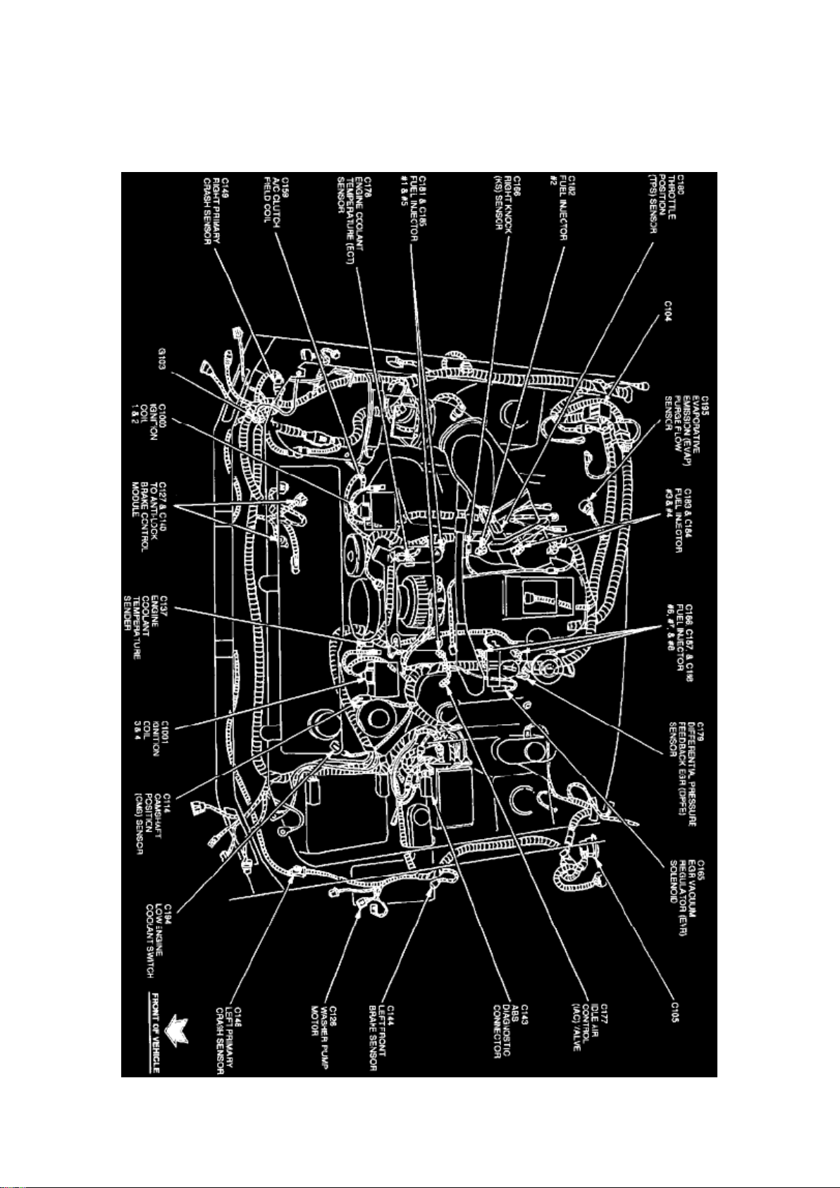
Electronic Brake Control Module: Locations
Engine View
The Anti-Lock Brake Control Module is located at the RH front of the engine compartment, behind
radiator.
Page 37
Ford Mustang Workshop Manual (V8-4.6L DOHC (1996))
Ford Workshop Manuals > Relays and Modules > Relays and Modules - Brakes and Traction Control > Electronic Brake
Control Module > Component Information > Locations > Page 43
Page 38

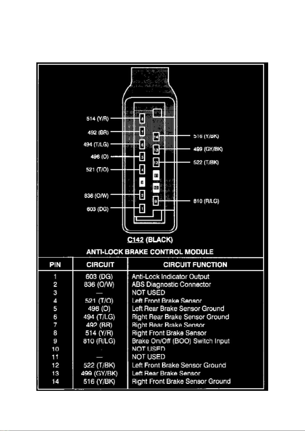
Electronic Brake Control Module: Diagrams
Anti-Lock Brake Control Module C142
Page 39
Ford Mustang Workshop Manual (V8-4.6L DOHC (1996))
Ford Workshop Manuals > Relays and Modules > Relays and Modules - Brakes and Traction Control > Electronic Brake
Control Module > Component Information > Locations > Page 44
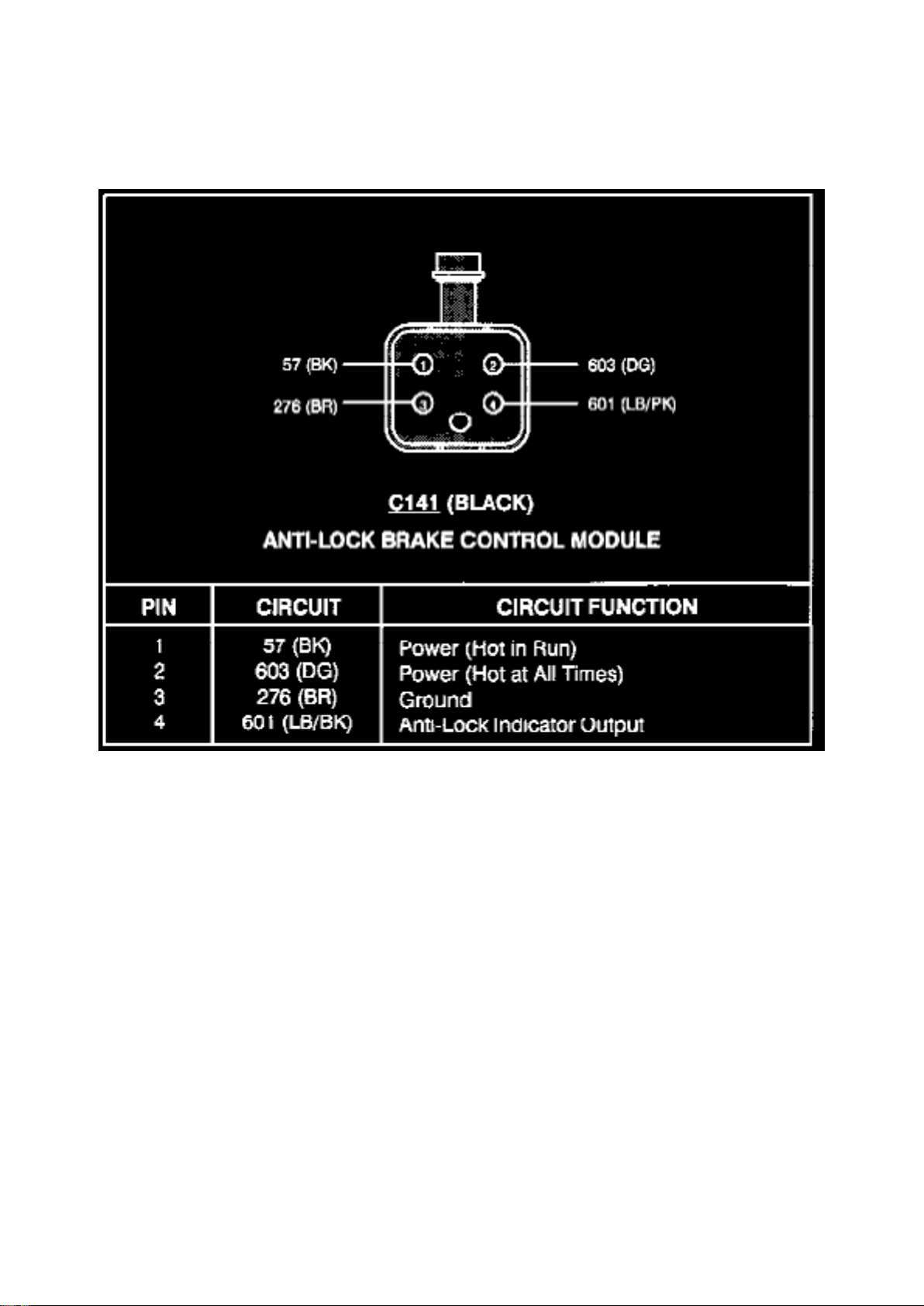
Anti-Lock Brake Control Module C141
Page 40
Ford Mustang Workshop Manual (V8-4.6L DOHC (1996))
Ford Workshop Manuals > Relays and Modules > Relays and Modules - Brakes and Traction Control > Electronic Brake
Control Module > Component Information > Locations > Page 45
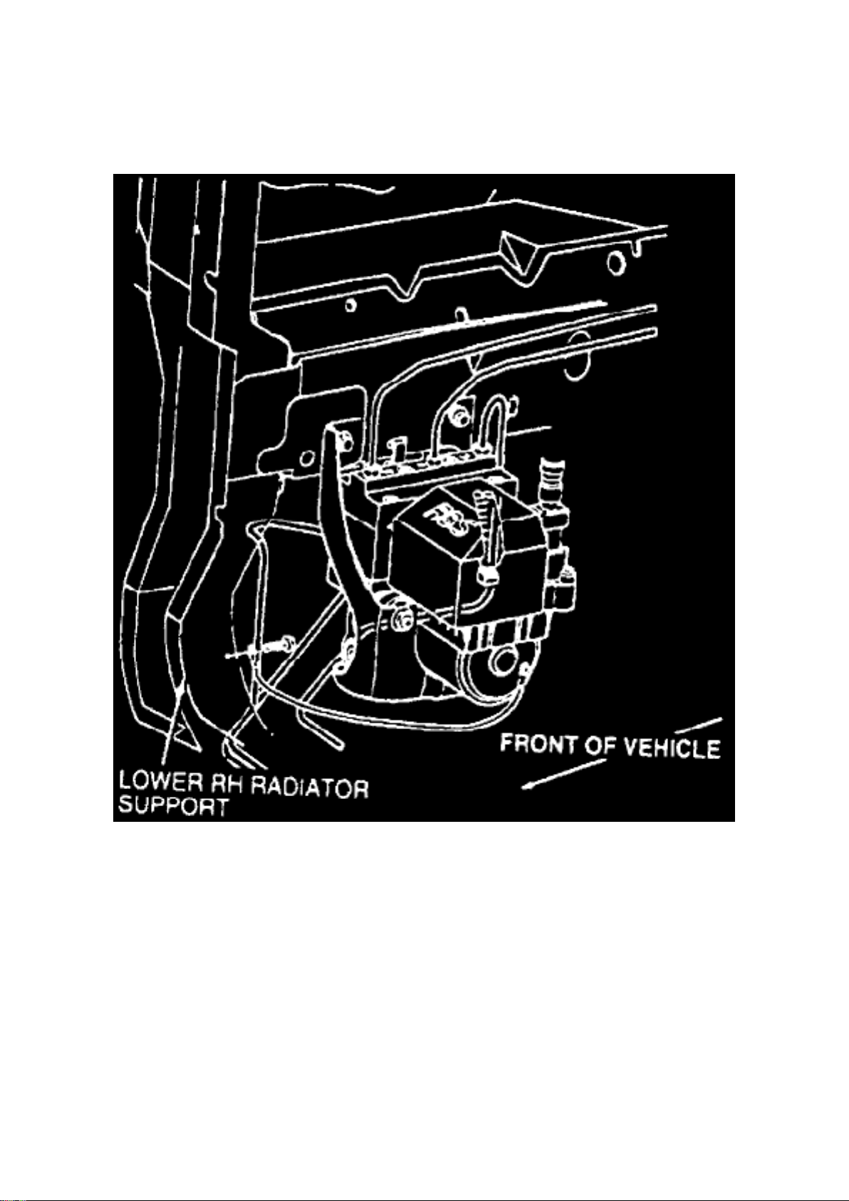
Electronic Brake Control Module: Description and Operation
Fig. 1 ABS Hydraulic Control Unit & Anti-Lock Brake Control Module
The anti-lock hydraulic control unit and anti-lock brake control module are a complete assembly.
The assembly is located in the righthand lower front corner of the engine compartment, next to the
bottom of the radiator coolant recovery reservoir. The unit is mounted in a bracket, attached to the
righthand frame rail. Both the control unit and control module have on-board diagnostics.
Page 41

Ford Mustang Workshop Manual (V8-4.6L DOHC (1996))
Ford Workshop Manuals > Relays and Modules > Relays and Modules - Brakes and Traction Control > Electronic Brake
Control Module > Component Information > Locations > Page 46
Page 42

Electronic Brake Control Module: Service and Repair
1. Remove hydraulic assembly. 2. Remove Torx(r) head screw from black plastic cover, then the
cover. 3. Remove 15- and 4-pin connectors. 4. Remove six anti-lock brake control module to
hydraulic control unit Torx(r) head bolts. 5. Remove control module by pulling straight up over
ground post. 6. Reverse procedure to install.
Page 43

Ford Mustang Workshop Manual (V8-4.6L DOHC (1996))
Ford Workshop Manuals > Relays and Modules > Relays and Modules - Cooling System > Radiator Cooling Fan Control
Module > Component Information > Description and Operation
Page 44

Radiator Cooling Fan Control Module: Description and Operation
PURPOSE
The Constant Control Relay Module (CCRM) interfaces with the Powertrain Control Module (PCM)
to provide control of the cooling fan and A/C clutch. The module includes the PCM power relay to
provide power to the PCM. These relays are contained in one housing, resulting in longer service
life and reduced wiring requirements for operation.
CONSTRUCTION
The CCRM has one 24-pin connector. Relays contained in the housing are independent of one
another.
OPERATION
The relays contained within the CCRM are interdependent and work with each other. The following
describes the different relay functions within the CCRM:
EEC Power Relay
For any other circuit in the CCRM to operate, this circuit must be powered up. This prevents
actuators from being turned on without the EEC system having control over them.
Fuel Pump Relay
The fuel pump relay circuit controls the fuel pump. The PCM provides the ground circuit for the
primary side of the relay. The secondary side supplies Battery Voltage (B+) to the fuel pump itself.
Cooling Fan Motor Relay
The cooling fan motor is controlled during vehicle operation by the constant control relay module
(CCRM)(12B581) and powertrain control module (PCM)(12A650) which energizes the cooling fan
motor under the following conditions: -
When the engine temperature is higher than normal the cooling fan motor starts operating at 105°C
(221°F) and stops when temperature drops to 94°C (200°F).
- When vehicle A/C is on and vehicle speed does not provide enough natural airflow, the cooling
fan motor starts running at or below 69 km/h (43 mph) and stops at 77 km/h (48 mph).
Low Fan Control Relay
The Low Fan Control (LFC) relay controls the electric cooling fan. The primary control circuit of the
LFC relay is normally high (B+). In this state the low speed cooling fan runs continuously. To turn
the fan off, The PCM grounds this circuit, pulling it low (near zero volts). A "fail safe" is built into the
LFC circuit to run the fan anytime the EEC power relay is activated, should the PCM fail open
circuit.
High Fan Control Relay
The High Fan Control (HFC) relay circuit operates the high speed electric cooling fan. If the Engine
Coolant Temperature (ECT) sensor relays a high temperature or overheat condition to the PCM, it
activates the HFC. In order to turn the high speed cooling fan on, the PCM grounds the primary
circuit of the HFC relay. The secondary circuit applies B+ to the cooling fan motor.
Wide Open Throttle A/C Control Relay
This circuit controls the A/C compressor clutch during normal operation. This circuit also
disengages the A/C clutch as commanded by the PCM during Wide Open Throttle (WOT)
Page 45

conditions. This solid state relay has two control circuits. One is used to engage the A/C clutch
upon demand from the vehicle operator and the A/C cycling pressure switch. The other control is
used to disengage the clutch upon command from the PCM.
Power Ground
This circuit provides the CCRM with a ground source for operating various controls. The circuit
uses one pin that goes to the battery negative terminal.
Page 46

Ford Mustang Workshop Manual (V8-4.6L DOHC (1996))
Ford Workshop Manuals > Relays and Modules > Relays and Modules - Cooling System > Radiator Cooling Fan Control
Module > Component Information > Description and Operation > Page 51
Page 47

Radiator Cooling Fan Control Module: Service and Repair
1. Disconnect battery ground cable, then electrical connector from module. 2. Remove module
bracket retainers and bracket from radiator support, then separate module from bracket. 3.
Reverse procedure to install.
Page 48

Ford Mustang Workshop Manual (V8-4.6L DOHC (1996))
Ford Workshop Manuals > Relays and Modules > Relays and Modules - Cooling System > Radiator Cooling Fan Motor
Relay > Component Information > Technical Service Bulletins > Engine Cooling Fan Module - Service Information
Page 49

Radiator Cooling Fan Motor Relay: Technical Service Bulletins Engine Cooling Fan Module Service Information
Article No. 97-10-4
05/12/97
^ ENGINE COOLING FAN - MODULE COMPONENT SERVICE INFORMATION
^ COOLING FAN - MODULE COMPONENT SERVICE INFORMATION
FORD: 1994-97 ESCORT, MUSTANG, TAURUS 1995-97 CONTOUR
LINCOLN-MERCURY: 1994-97 CONTINENTAL, MARK VIII, SABLE, TRACER 1995-97
MYSTIQUE
LIGHT TRUCK: 1994-97 VILLAGER, WINDSTAR
ISSUE: Currently, Service Manuals indicate that the Motor and Fan Assembly-Engine Cooling
(-80607-) should/can be serviced at the component level: Engine Cooling Fan Motor (-8k621-),
Shroud (-8146-), and Fan Blade (-8600-). This information is incorrect. The Motor and Fan
Assembly-Engine Cooling (-8C607-) should only be serviced as an assembly. The assembly is
dynamically balanced at the Original Equipment Manufacturer and should not be disassembled into
its component parts. If the assembly is serviced at the component level, the assembly balance
could be adversely affected, and a possible durability and Noise/Vibration/Harshness (NVH) issue
may arise.
ACTION: Service only the Motor and Fan Assembly-Engine Cooling (-8C607-). Do not service the
Engine Cooling Fan Motor (-8K621-), Shroud (-8146-), or the Fan Blade (-8600-). Servicing only
the assembly will eliminate durability and NVH issues related to component replacement. Refer to
the following text for details.
Electric Cooling Fan Blades (-8600-), Motors (-8K621-), and Shrouds (-8146-) will no longer be
serviced separately. These components will only be serviced in Cooling Fan Module Assemblies
(-8C607-). Refer to the Ford Part Manuals Base (-8C607-) for part number.
OTHER APPLICABLE ARTICLES: NONE WARRANTY STATUS: INFORMATION ONLY OASIS
CODES: 208000, 208999, 290000, 402000, 490000, 702000
Page 50
Ford Mustang Workshop Manual (V8-4.6L DOHC (1996))
Ford Workshop Manuals > Relays and Modules > Relays and Modules - Cooling System > Radiator Cooling Fan Motor
Relay > Component Information > Technical Service Bulletins > Page 56
Page 51

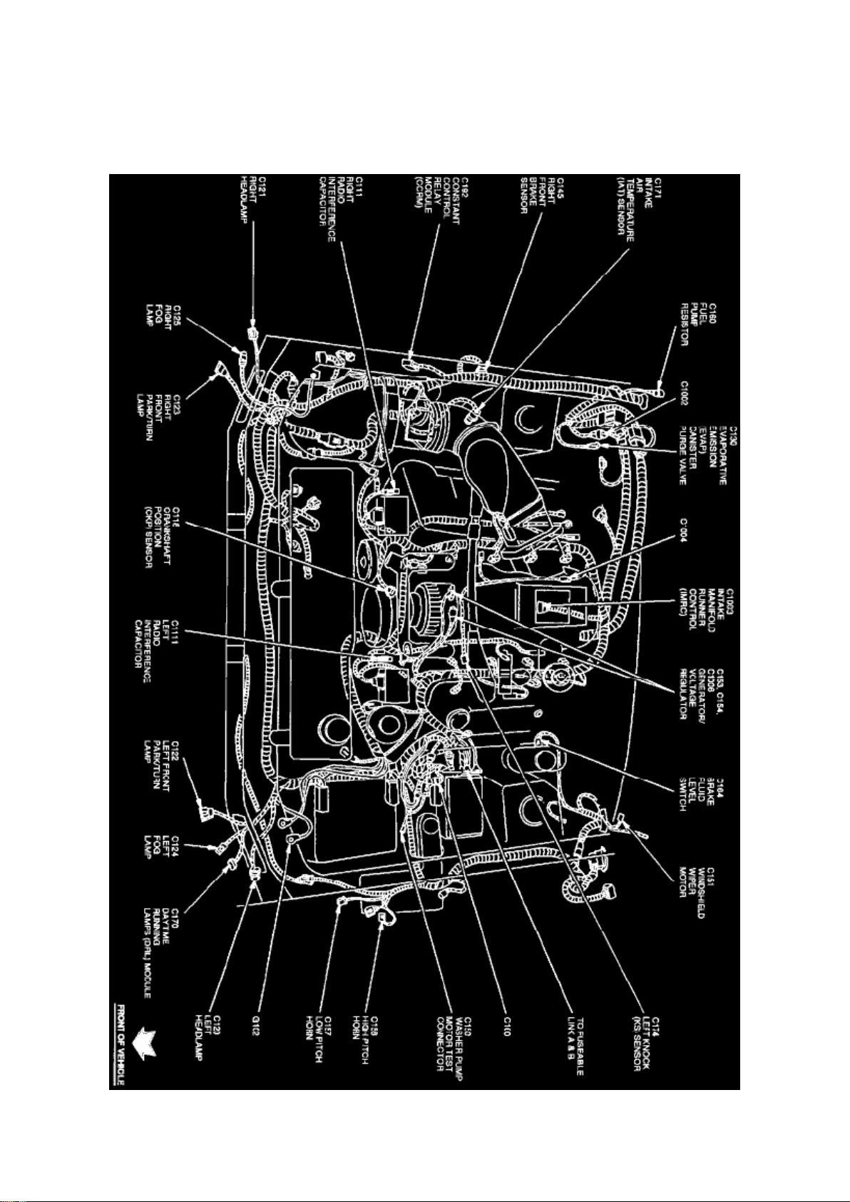
Radiator Cooling Fan Motor Relay: Locations
Engine View
Page 52
Ford Mustang Workshop Manual (V8-4.6L DOHC (1996))
Ford Workshop Manuals > Relays and Modules > Relays and Modules - Cooling System > Radiator Cooling Fan Motor
Relay > Component Information > Technical Service Bulletins > Page 57
Page 53

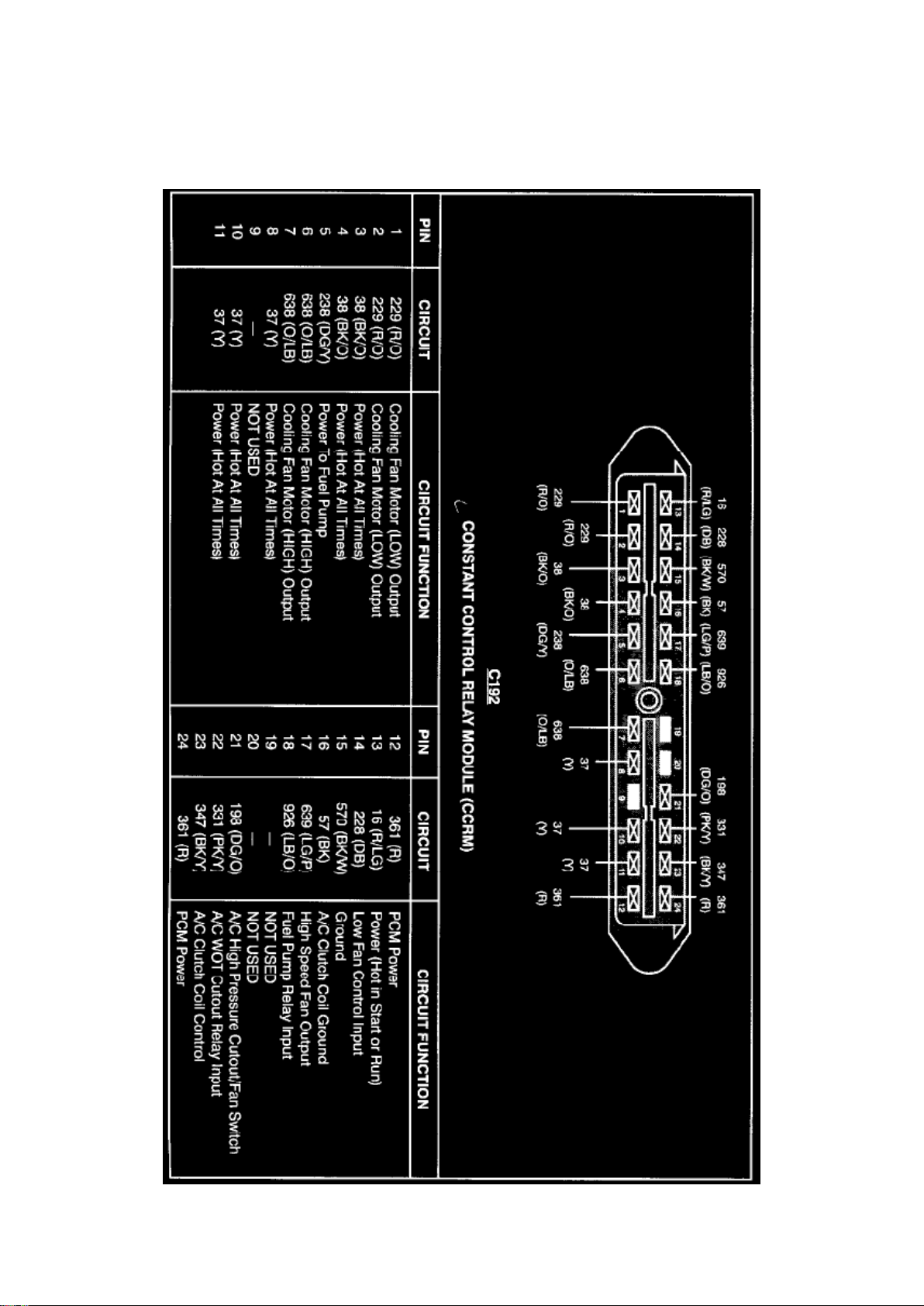
Constant Control Relay Module
Page 54

Ford Mustang Workshop Manual (V8-4.6L DOHC (1996))
Ford Workshop Manuals > Relays and Modules > Relays and Modules - Cooling System > Radiator Cooling Fan Motor
Relay > Component Information > Technical Service Bulletins > Page 58
Page 55

Radiator Cooling Fan Motor Relay: Description and Operation
PURPOSE
The Constant Control Relay Module (CCRM) interfaces with the Powertrain Control Module (PCM)
to provide control of the cooling fan and A/C clutch. The module includes the PCM power relay to
provide power to the PCM. These relays are contained in one housing, resulting in longer service
life and reduced wiring requirements for operation.
CONSTRUCTION
The CCRM has one 24-pin connector. Relays contained in the housing are independent of one
another.
OPERATION
The relays contained within the CCRM are interdependent and work with each other. The following
describes the different relay functions within the CCRM:
EEC Power Relay
For any other circuit in the CCRM to operate, this circuit must be powered up. This prevents
actuators from being turned on without the EEC system having control over them.
Fuel Pump Relay
The fuel pump relay circuit controls the fuel pump. The PCM provides the ground circuit for the
primary side of the relay. The secondary side supplies Battery Voltage (B+) to the fuel pump itself.
Cooling Fan Motor Relay
The cooling fan motor is controlled during vehicle operation by the constant control relay module
(CCRM)(12B581) and powertrain control module (PCM)(12A650) which energizes the cooling fan
motor under the following conditions: -
When the engine temperature is higher than normal the cooling fan motor starts operating at 105°C
(221°F) and stops when temperature drops to 94°C (200°F).
- When vehicle A/C is on and vehicle speed does not provide enough natural airflow, the cooling
fan motor starts running at or below 69 km/h (43 mph) and stops at 77 km/h (48 mph).
Low Fan Control Relay
The Low Fan Control (LFC) relay controls the electric cooling fan. The primary control circuit of the
LFC relay is normally high (B+). In this state the low speed cooling fan runs continuously. To turn
the fan off, The PCM grounds this circuit, pulling it low (near zero volts). A "fail safe" is built into the
LFC circuit to run the fan anytime the EEC power relay is activated, should the PCM fail open
circuit.
High Fan Control Relay
The High Fan Control (HFC) relay circuit operates the high speed electric cooling fan. If the Engine
Coolant Temperature (ECT) sensor relays a high temperature or overheat condition to the PCM, it
activates the HFC. In order to turn the high speed cooling fan on, the PCM grounds the primary
circuit of the HFC relay. The secondary circuit applies B+ to the cooling fan motor.
Wide Open Throttle A/C Control Relay
This circuit controls the A/C compressor clutch during normal operation. This circuit also
disengages the A/C clutch as commanded by the PCM during Wide Open Throttle (WOT)
Page 56

conditions. This solid state relay has two control circuits. One is used to engage the A/C clutch
upon demand from the vehicle operator and the A/C cycling pressure switch. The other control is
used to disengage the clutch upon command from the PCM.
Power Ground
This circuit provides the CCRM with a ground source for operating various controls. The circuit
uses one pin that goes to the battery negative terminal.
Page 57
Ford Mustang Workshop Manual (V8-4.6L DOHC (1996))
Ford Workshop Manuals > Relays and Modules > Relays and Modules - Cruise Control > Cruise Control Module >
Component Information > Diagrams
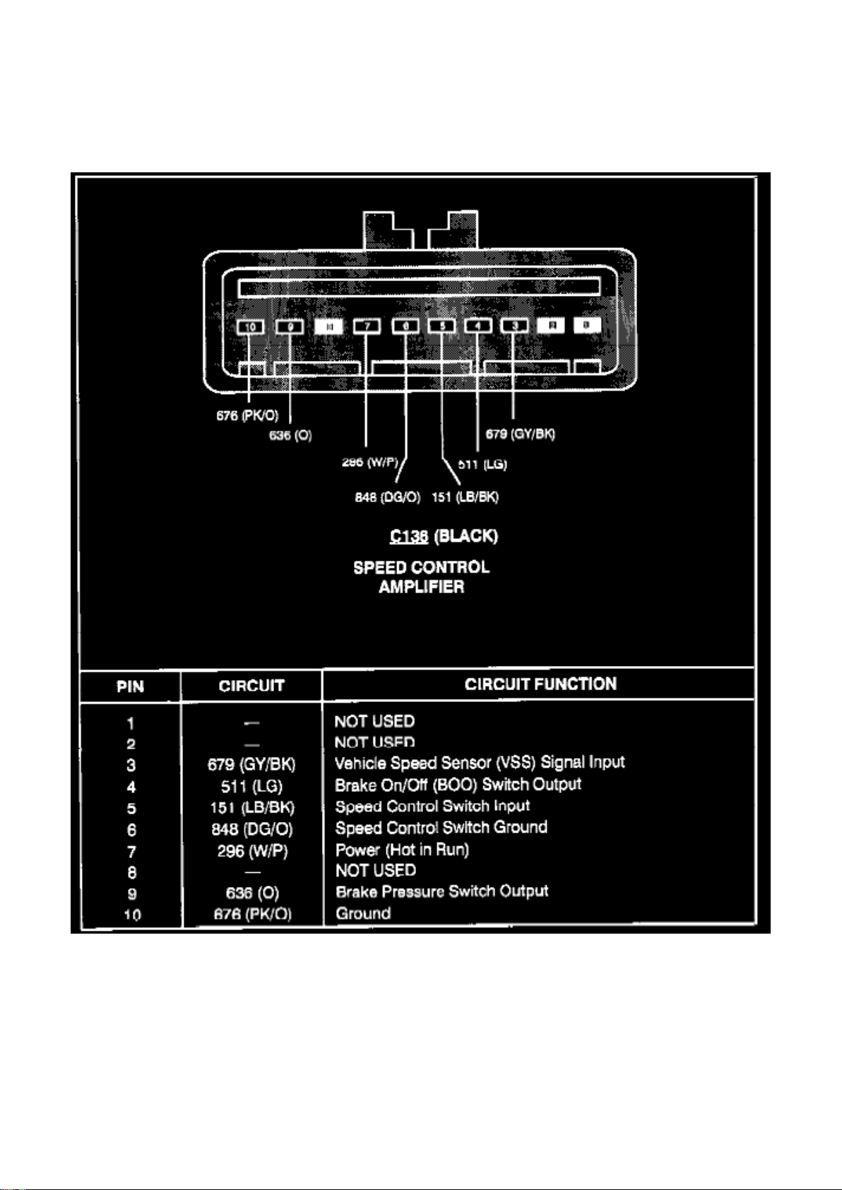
Speed Control amplifier
Page 58
Ford Mustang Workshop Manual (V8-4.6L DOHC (1996))
Ford Workshop Manuals > Relays and Modules > Relays and Modules - Engine > Oil Level Warning Indicator Relay >
Component Information > Locations
Page 59

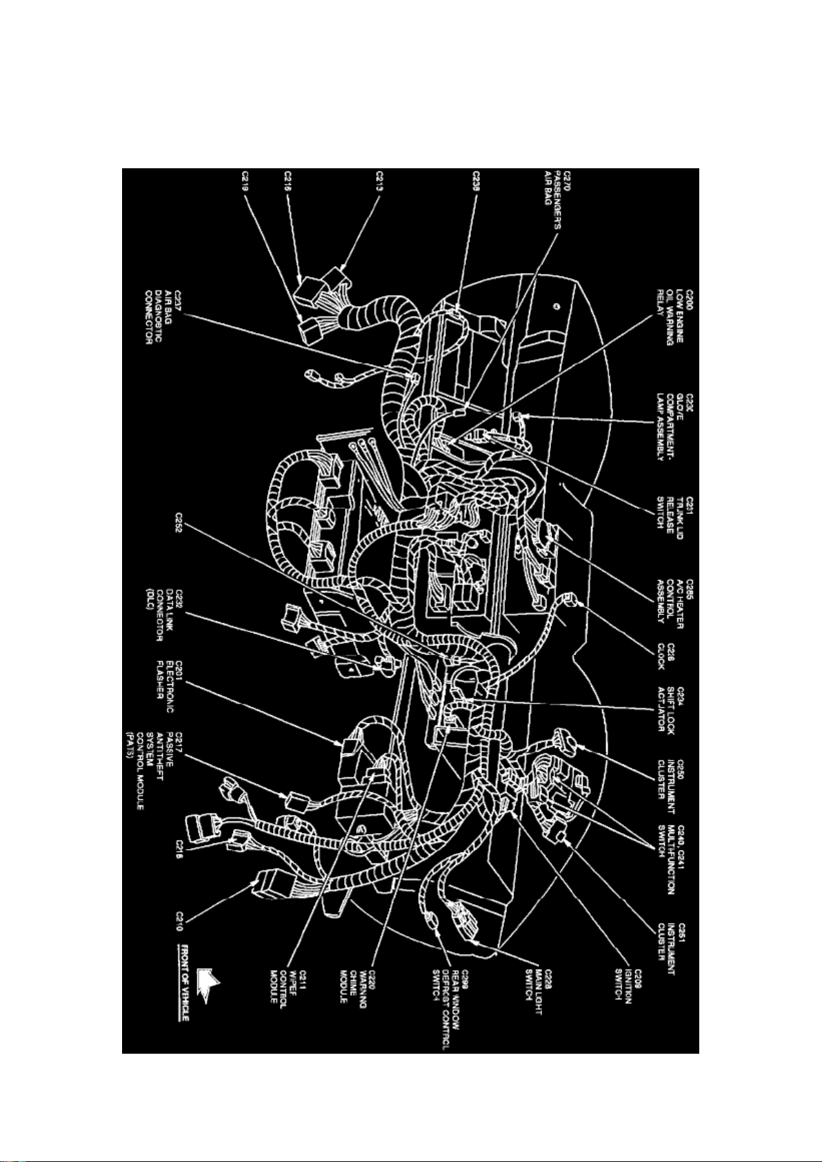
Oil Level Warning Indicator Relay: Locations
Instrument Panel View
The Low Engine Oil Warning Relay is located behind instrument panel, at the LH side of steering
column brace.
Page 60
Ford Mustang Workshop Manual (V8-4.6L DOHC (1996))
Ford Workshop Manuals > Relays and Modules > Relays and Modules - Engine > Oil Level Warning Indicator Relay >
Component Information > Locations > Page 67
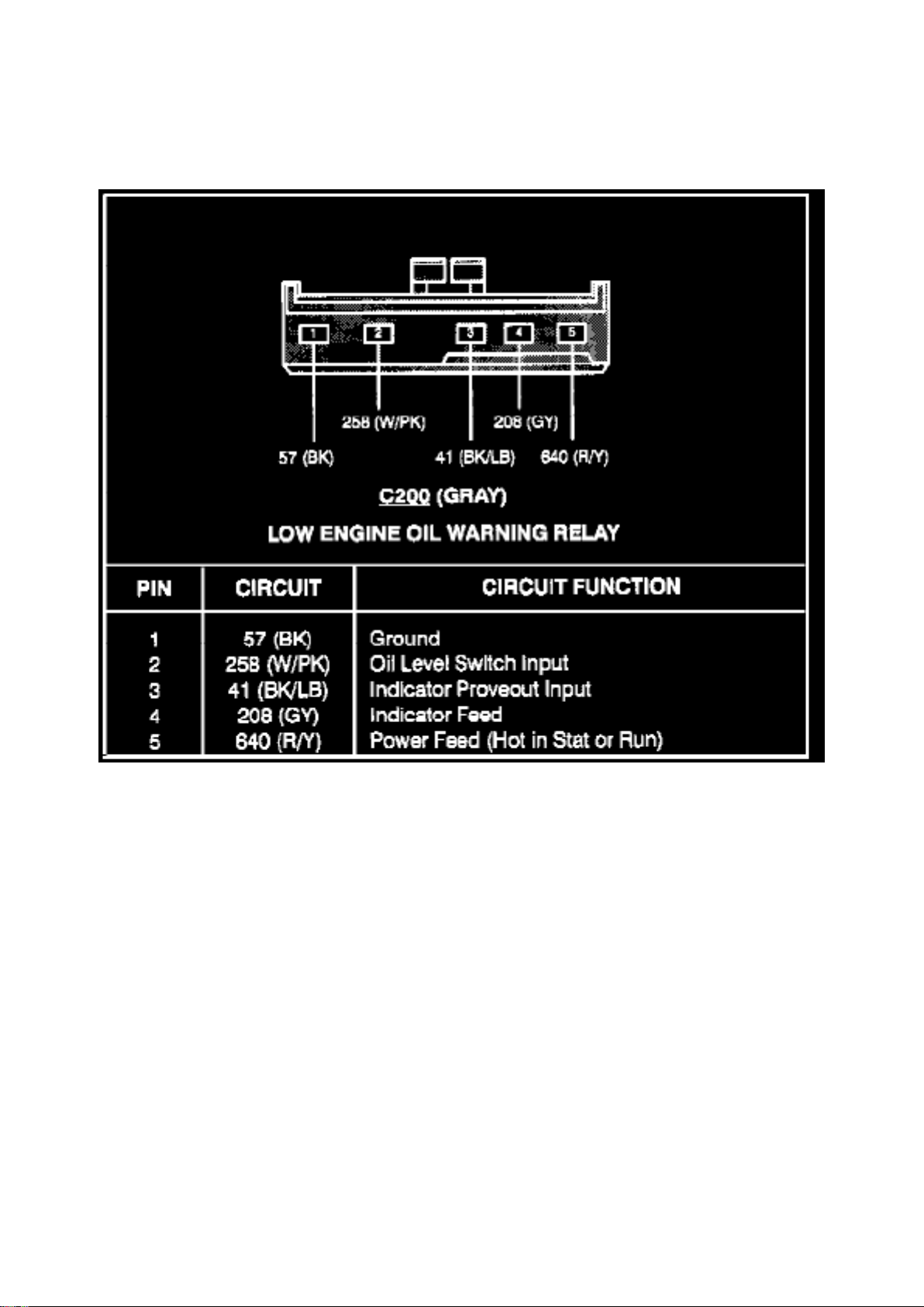
Low Engine Oil Warning Relay
Page 61
Ford Mustang Workshop Manual (V8-4.6L DOHC (1996))
Ford Workshop Manuals > Relays and Modules > Relays and Modules - HVAC > Compressor Clutch Relay > Component
Information > Locations
Page 62

Compressor Clutch Relay: Locations
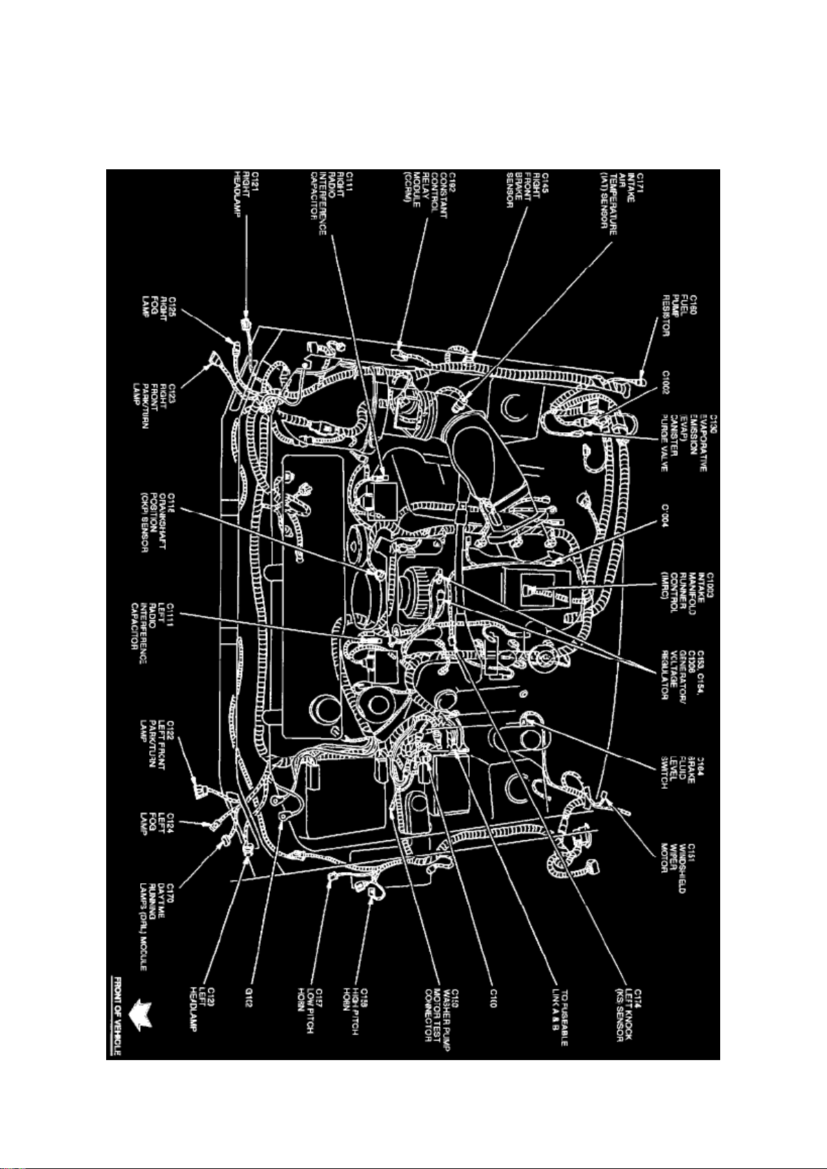
Engine View
Page 63
Ford Mustang Workshop Manual (V8-4.6L DOHC (1996))
Ford Workshop Manuals > Relays and Modules > Relays and Modules - HVAC > Compressor Clutch Relay > Component
Information > Locations > Page 72
Page 64

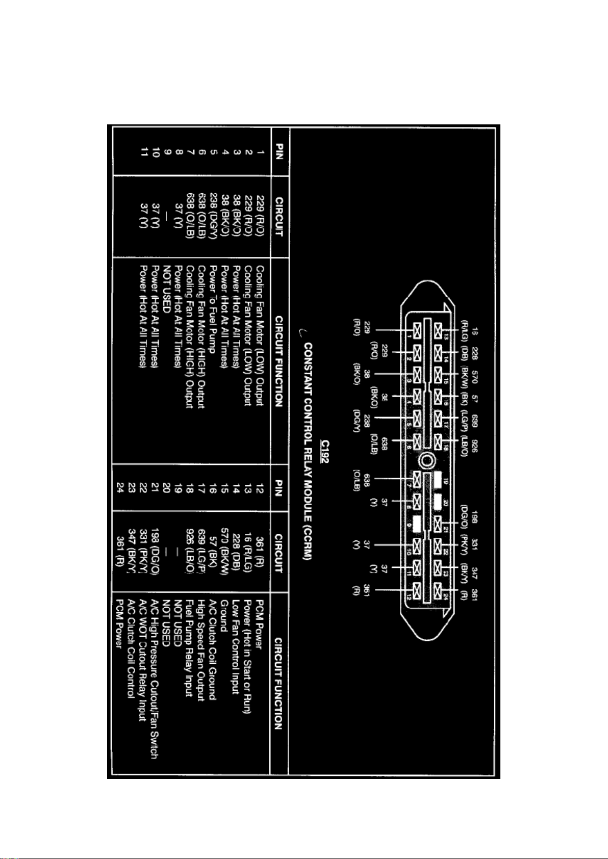
Constant Control Relay Module
Page 65

Ford Mustang Workshop Manual (V8-4.6L DOHC (1996))
Ford Workshop Manuals > Relays and Modules > Relays and Modules - HVAC > Compressor Clutch Relay > Component
Information > Locations > Page 73
Page 66

Compressor Clutch Relay: Description and Operation
PURPOSE
The Constant Control Relay Module (CCRM) interfaces with the Powertrain Control Module (PCM)
to provide control of the cooling fan and A/C clutch. The module includes the PCM power relay to
provide power to the PCM. These relays are contained in one housing, resulting in longer service
life and reduced wiring requirements for operation.
CONSTRUCTION
The CCRM has one 24-pin connector. Relays contained in the housing are independent of one
another.
OPERATION
The relays contained within the CCRM are interdependent and work with each other. The following
describes the different relay functions within the CCRM:
EEC Power Relay
For any other circuit in the CCRM to operate, this circuit must be powered up. This prevents
actuators from being turned on without the EEC system having control over them.
Fuel Pump Relay
The fuel pump relay circuit controls the fuel pump. The PCM provides the ground circuit for the
primary side of the relay. The secondary side supplies Battery Voltage (B+) to the fuel pump itself.
Cooling Fan Motor Relay
The cooling fan motor is controlled during vehicle operation by the constant control relay module
(CCRM)(12B581) and powertrain control module (PCM)(12A650) which energizes the cooling fan
motor under the following conditions: -
When the engine temperature is higher than normal the cooling fan motor starts operating at 105°C
(221°F) and stops when temperature drops to 94°C (200°F).
- When vehicle A/C is on and vehicle speed does not provide enough natural airflow, the cooling
fan motor starts running at or below 69 km/h (43 mph) and stops at 77 km/h (48 mph).
Low Fan Control Relay
The Low Fan Control (LFC) relay controls the electric cooling fan. The primary control circuit of the
LFC relay is normally high (B+). In this state the low speed cooling fan runs continuously. To turn
the fan off, The PCM grounds this circuit, pulling it low (near zero volts). A "fail safe" is built into the
LFC circuit to run the fan anytime the EEC power relay is activated, should the PCM fail open
circuit.
High Fan Control Relay
The High Fan Control (HFC) relay circuit operates the high speed electric cooling fan. If the Engine
Coolant Temperature (ECT) sensor relays a high temperature or overheat condition to the PCM, it
activates the HFC. In order to turn the high speed cooling fan on, the PCM grounds the primary
circuit of the HFC relay. The secondary circuit applies B+ to the cooling fan motor.
Wide Open Throttle A/C Control Relay
This circuit controls the A/C compressor clutch during normal operation. This circuit also
disengages the A/C clutch as commanded by the PCM during Wide Open Throttle (WOT)
Page 67

conditions. This solid state relay has two control circuits. One is used to engage the A/C clutch
upon demand from the vehicle operator and the A/C cycling pressure switch. The other control is
used to disengage the clutch upon command from the PCM.
Power Ground
This circuit provides the CCRM with a ground source for operating various controls. The circuit
uses one pin that goes to the battery negative terminal.
Page 68
Ford Mustang Workshop Manual (V8-4.6L DOHC (1996))
Ford Workshop Manuals > Relays and Modules > Relays and Modules - Instrument Panel > Audible Warning Device
Control Module > Component Information > Locations
Page 69

Audible Warning Device Control Module: Locations
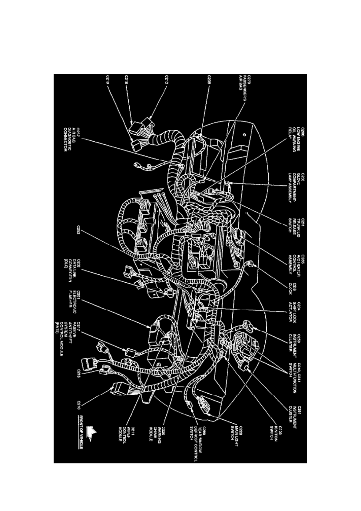
Instrument Panel View
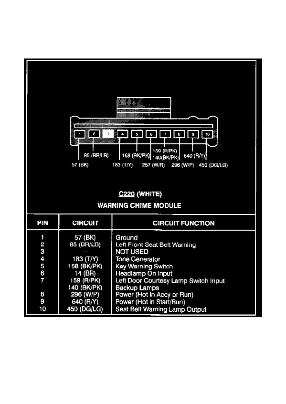
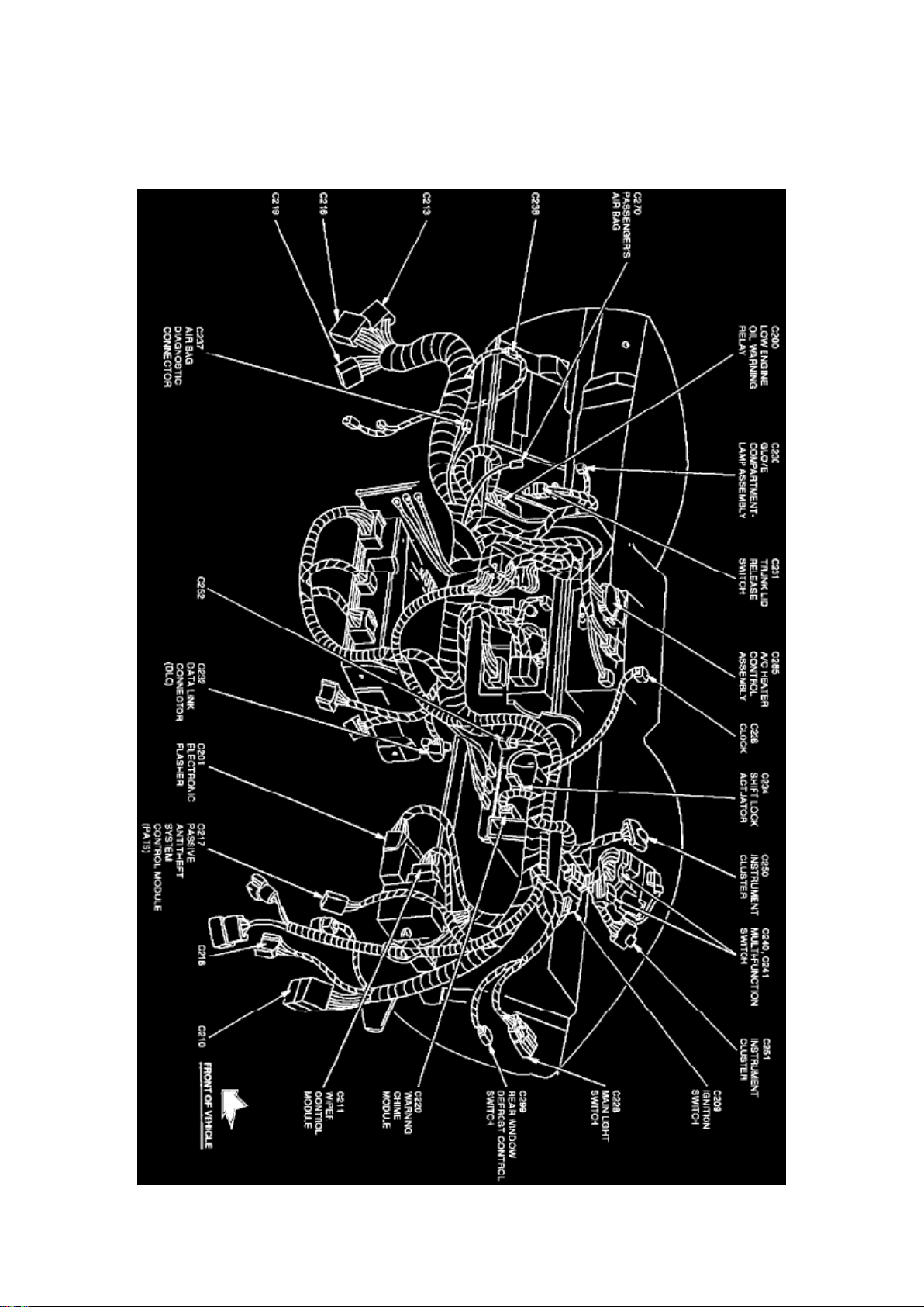
The Warning Chime Module is located behind center of the instrument panel, RH side of the radio.
Page 70
Ford Mustang Workshop Manual (V8-4.6L DOHC (1996))
Ford Workshop Manuals > Relays and Modules > Relays and Modules - Instrument Panel > Audible Warning Device
Control Module > Component Information > Locations > Page 78
Warning Chime Module
Page 71
Ford Mustang Workshop Manual (V8-4.6L DOHC (1996))
Ford Workshop Manuals > Relays and Modules > Relays and Modules - Instrument Panel > Oil Level Warning Indicator
Relay > Component Information > Locations
Page 72

Oil Level Warning Indicator Relay: Locations
Instrument Panel View
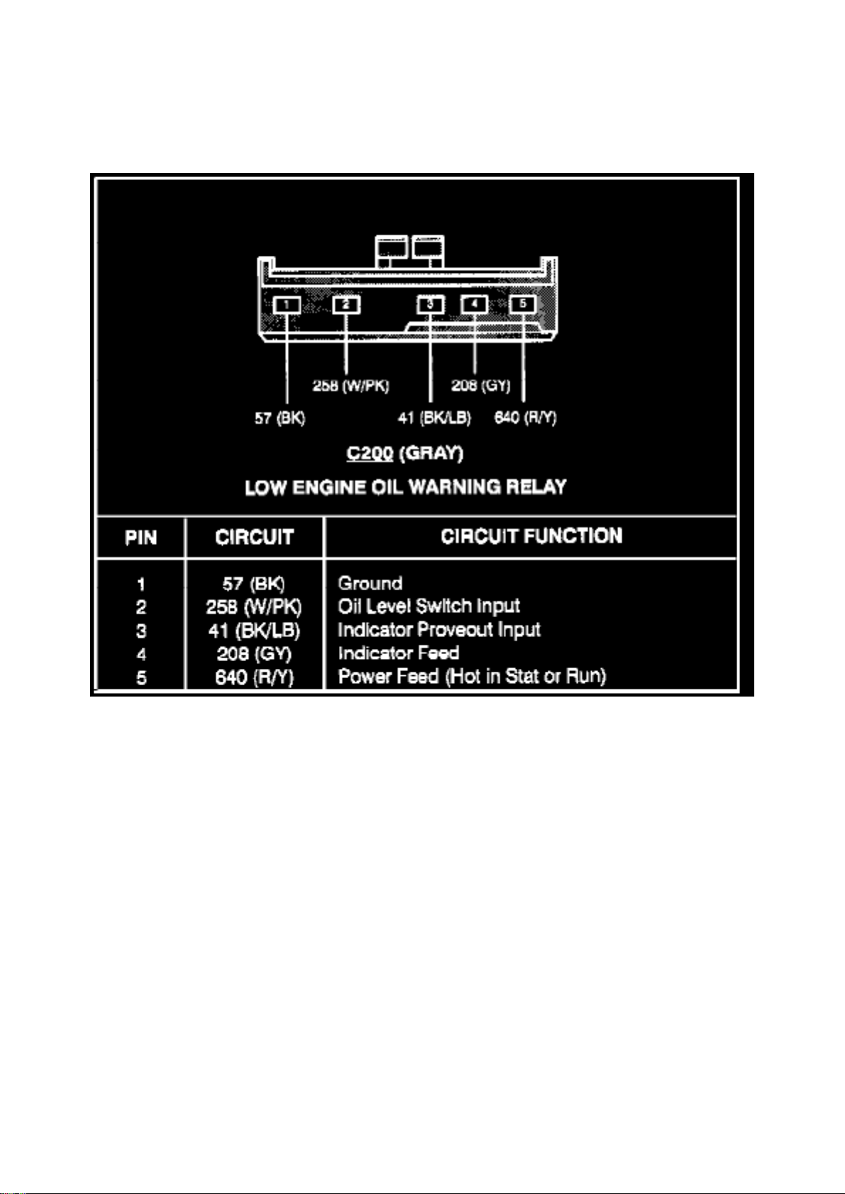
The Low Engine Oil Warning Relay is located behind instrument panel, at the LH side of steering
column brace.
Page 73
Ford Mustang Workshop Manual (V8-4.6L DOHC (1996))
Ford Workshop Manuals > Relays and Modules > Relays and Modules - Instrument Panel > Oil Level Warning Indicator
Relay > Component Information > Locations > Page 82
Low Engine Oil Warning Relay
Page 74
Ford Mustang Workshop Manual (V8-4.6L DOHC (1996))
Ford Workshop Manuals > Relays and Modules > Relays and Modules - Lighting and Horns > Daytime Running Lamp
Control Unit > Component Information > Locations
Page 75

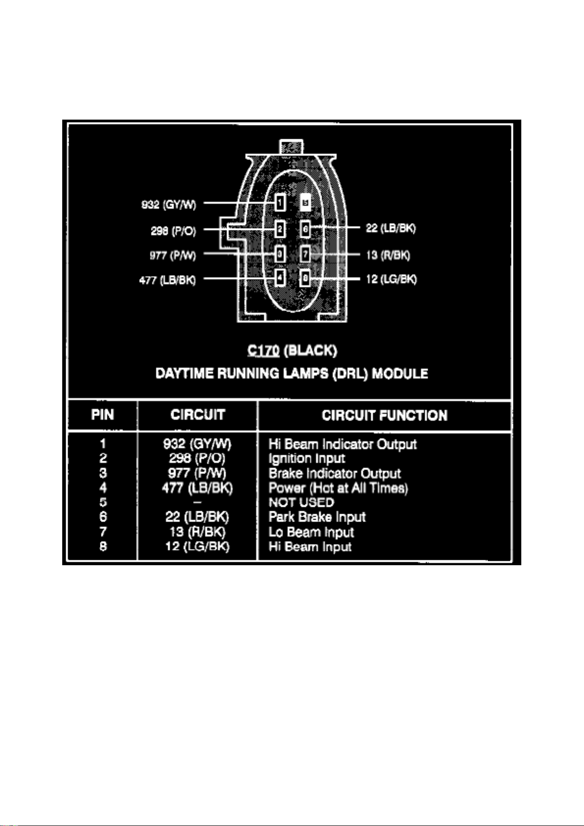
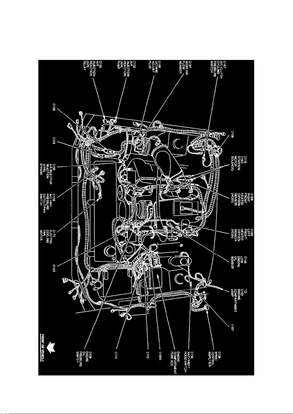
Daytime Running Lamp Control Unit: Locations
Engine View
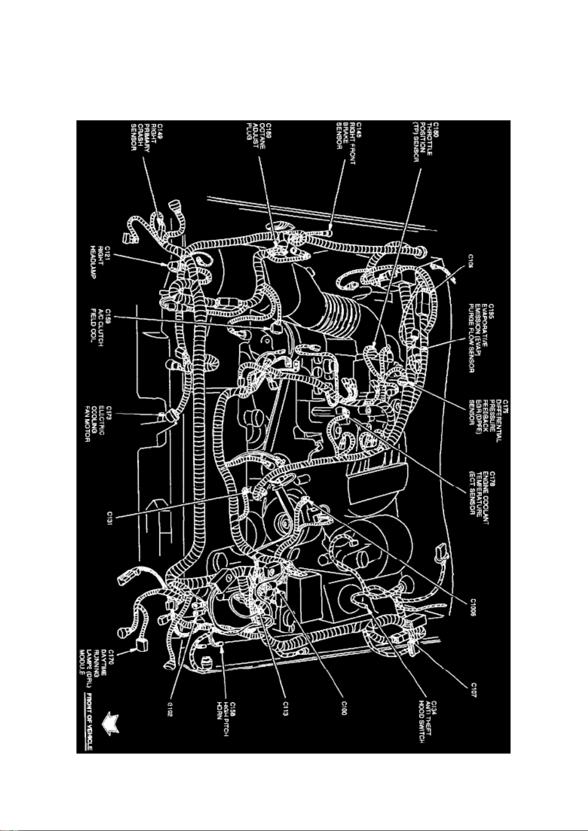
The Daytime Running Lamps Module is located in front of the LH front fender, below horns.
Page 76
Ford Mustang Workshop Manual (V8-4.6L DOHC (1996))
Ford Workshop Manuals > Relays and Modules > Relays and Modules - Lighting and Horns > Daytime Running Lamp
Control Unit > Component Information > Locations > Page 87
Daytime Running Lamps Module
Page 77
Ford Mustang Workshop Manual (V8-4.6L DOHC (1996))
Ford Workshop Manuals > Relays and Modules > Relays and Modules - Lighting and Horns > Fog/Driving Lamp Relay >
Component Information > Locations
Page 78

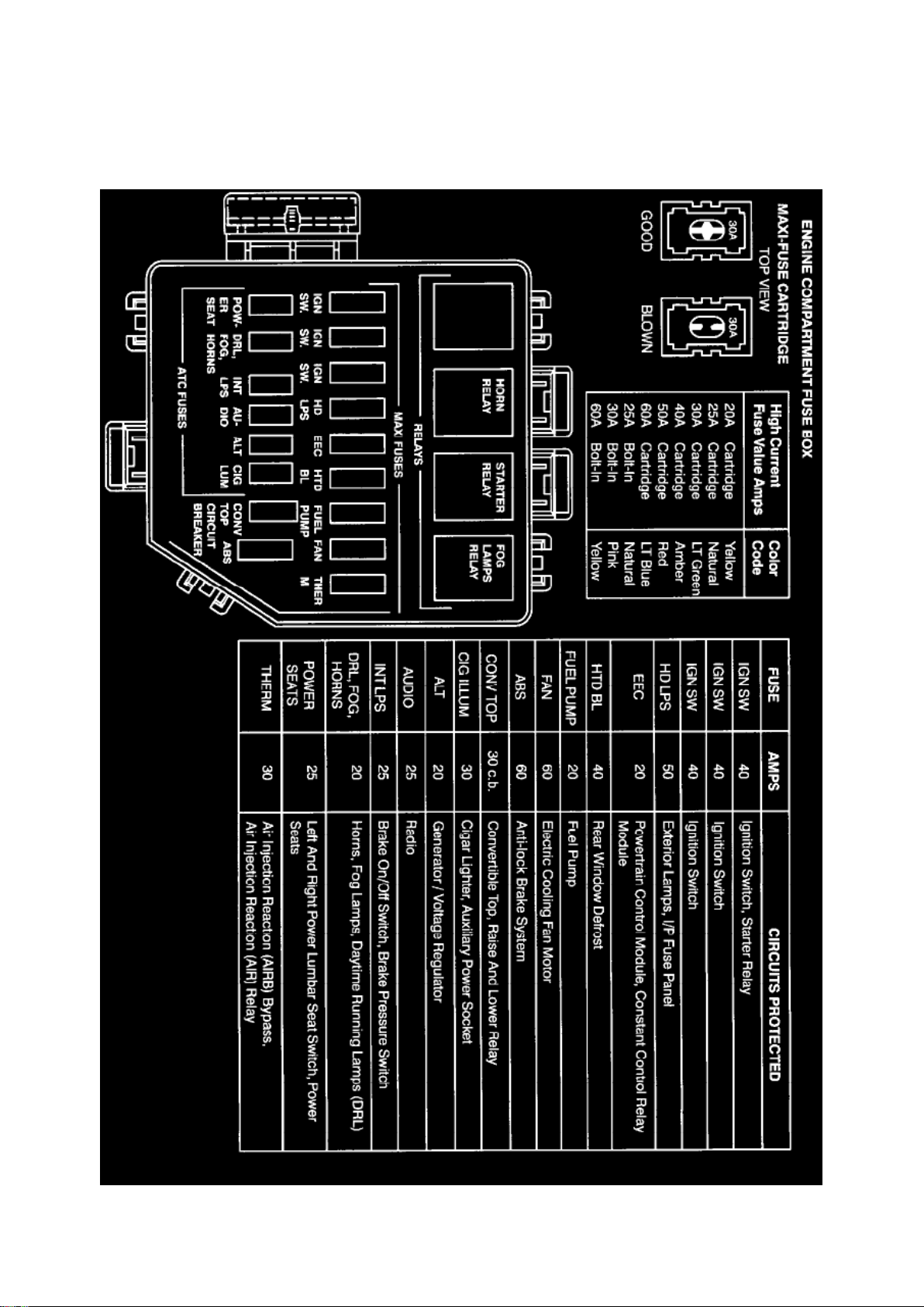
Fog/Driving Lamp Relay: Locations
Engine View
Page 79
Ford Mustang Workshop Manual (V8-4.6L DOHC (1996))
Ford Workshop Manuals > Relays and Modules > Relays and Modules - Lighting and Horns > Fog/Driving Lamp Relay >
Component Information > Locations > Page 91
Page 80

Engine Compartment Fuse Box
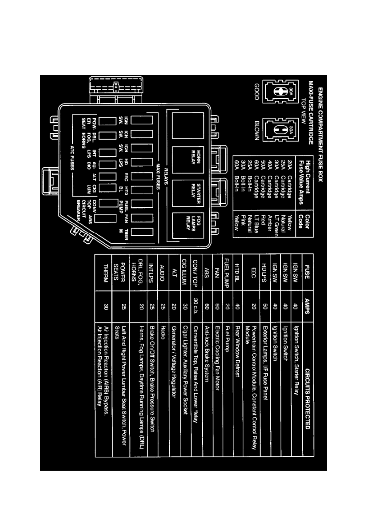
The Fog Lamp Relay is located at the LH side of engine compartment in the engine compartment
fuse box.
Page 81
Ford Mustang Workshop Manual (V8-4.6L DOHC (1996))
Ford Workshop Manuals > Relays and Modules > Relays and Modules - Lighting and Horns > Horn Relay > Component
Information > Locations
Page 82

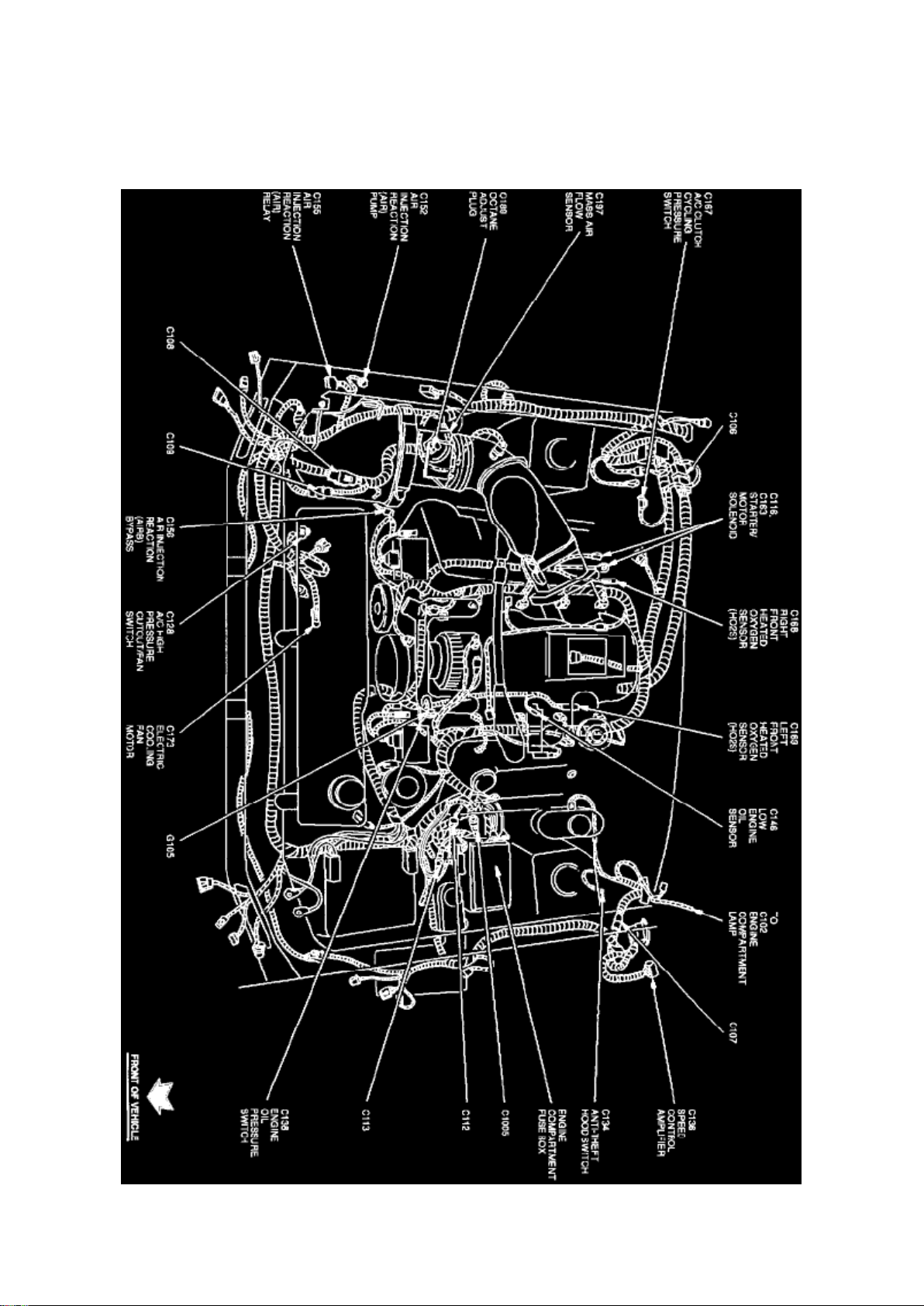
Horn Relay: Locations
Engine View
Page 83
Ford Mustang Workshop Manual (V8-4.6L DOHC (1996))
Ford Workshop Manuals > Relays and Modules > Relays and Modules - Lighting and Horns > Horn Relay > Component
Information > Locations > Page 95
Page 84

Engine Compartment Fuse Box
Horn Relay is located at the LH side of engine compartment, in engine compartment fuse box.
Page 85

Ford Mustang Workshop Manual (V8-4.6L DOHC (1996))
Ford Workshop Manuals > Relays and Modules > Relays and Modules - Powertrain Management > Relays and Modules Computers and Control Systems > Engine Control Module > Component Information > Technical Service Bulletins >
Customer Interest: > 96179 > Aug > 96 > PCM - MIL ON/DTCs P0300 through P0308 Stored
Page 86

Engine Control Module: Customer Interest PCM - MIL ON/DTCs P0300 through P0308 Stored
Page 87

Article No. 96-179
08/12/96
^ MALFUNCTION INDICATOR LAMP (MIL) ILLUMINATION - DIAGNOSTIC TROUBLE CODES
(DTCS) P0300, P0301, P03O2, P0303, P0304, P0305, P0306, P0307, OR P0308 IN MEMORY NO DRIVEABILITY CONCERNS PRESENT - VEHICLES BUILT WITH 3.8L, 4.2L, OR 4.6L
ENGINE
^ LAMP - MALFUNCTION INDICATOR LAMP (MIL) ILLUMINATION - DIAGNOSTIC TROUBLE
CODES (DTCS) P0300, P0301, P0302, P0303, P0304, P0305, P0306, P0307, OR P0308 IN
MEMORY - NO DRIVEABILITY CONCERNS - VEHICLES BUILT WITH 3.8L, 4.2L, OR 4.6L
ENGINE
FORD: 1996-97 MUSTANG, THUNDERBIRD
LINCOLN-MERCURY: 1996-97 COUGAR
LIGHT TRUCK: 1996-97 WINDSTAR 1997 E-150, F-150
ISSUE: The Malfunction Indicator Lamp (MIL) may illuminate and set Diagnostic Trouble Code(s)
(DTC) P0300, P0301, P0302, P0303, P0304, P0305, P0306, P0307, or P0308 on some vehicles.
This may be due to the pulse ring of the crankshaft pulley and damper assembly being removed,
replaced or reinstalled. This causes an incompatibility with the profile correction, or "learning", data
stored within the Powertrain Control Module (PCM), which will illuminate the MIL when the engine
is started
ACTION: Remove the negative battery cable for at least 5 minutes to erase the original profile
correction memory when removing, replacing, or reinstalling a pulse ring.
OTHER APPLICABLE ARTICLES: NONE
WARRANTY STATUS: INFORMATION ONLY
OASIS CODES: 206000, 499000, 698298
Page 88

Ford Mustang Workshop Manual (V8-4.6L DOHC (1996))
Ford Workshop Manuals > Relays and Modules > Relays and Modules - Powertrain Management > Relays and Modules Computers and Control Systems > Engine Control Module > Component Information > Technical Service Bulletins > All
Technical Service Bulletins for Engine Control Module: > 99-4-3 > Mar > 99 > PCM - Reprogramming Out of Vehicle
Page 89

Engine Control Module: All Technical Service Bulletins PCM - Reprogramming Out of Vehicle
Page 90

Article No. 99-4-3
03/08/99
REPROGRAMMING POWERTRAIN CONTROL MODULES (PCMS) - OUT-OF-VEHICLE - EEC V
VEHICLES ONLY
FORD: 1994-97 THUNDERBIRD 1994-99 MUSTANG 1995-99 CROWN VICTORIA 1996-97
PROBE 1996-99 CONTOUR, ESCORT, TAURUS
LINCOLN-MERCURY: 1994-97 COUGAR 1995-99 CONTINENTAL, GRAND MARQUIS, TOWN
CAR 1996-98 MARK VIII 1996-99 MYSTIQUE, SABLE, TRACER 1999 COUGAR
LIGHT TRUCK: 1994-97 F SUPER DUTY, F-250 HD, F-350 1995-99 ECONOLINE, RANGER,
WINDSTAR 1996 BRONCO 1996-97 AEROSTAR 1996-99 EXPLORER, F-150, F-250 LD 1997-99
EXPEDITION, MOUNTAINEER 1998-99 NAVIGATOR 1999 SUPER DUTY F SERIES
This TSB article is being republished in its entirety to update the affected vehicles and to include an
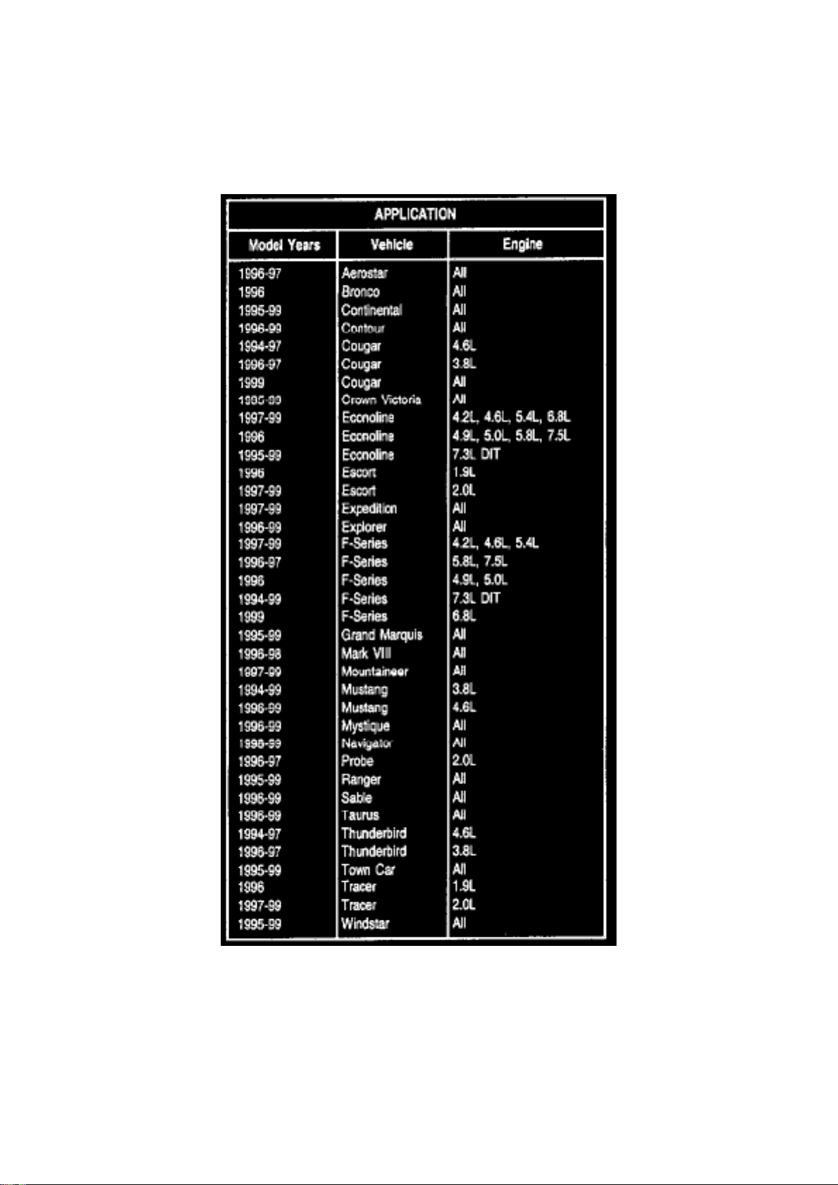
Application Chart for the affected vehicles.
ISSUE The Federal Environmental Protection Agency (EPA) has mandated that all aftermarket
service centers shall be able to either reprogram Powertrain Control Modules (PCMs) or obtain
reasonably priced, timely PCM programming services at dealerships. Ford has released an
out-of-vehicle EEC V reprogramming cable to support this requirement. Also, PCMs are
reprogrammable to update calibration levels or to reprogram a common hardware type to a new
calibration in order to fill a service need without ordering a new PCM.
Page 91
Ford Mustang Workshop Manual (V8-4.6L DOHC (1996))
Ford Workshop Manuals > Relays and Modules > Relays and Modules - Powertrain Management > Relays and Modules Computers and Control Systems > Engine Control Module > Component Information > Technical Service Bulletins > All
Technical Service Bulletins for Engine Control Module: > 99-4-3 > Mar > 99 > PCM - Reprogramming Out of Vehicle > Page
111
ACTION Refer to the Application Chart in this article to use the new 15- to 104-Pin Flash Cable to
handle all necessary out-of-vehicle programming of EEC V modules in the vehicles listed. This may
allow added flexibility in servicing aftermarket and fleet accounts as well as provide the ability to
have modules updated to new calibrations through the Parts Department instead of ordering new
parts.
Page 92

Currently, EEC V modules must be installed in a vehicle to reprogram a new calibration in the
module. An aftermarket service center may bring a module to a dealership for a calibration update
or may request an updated calibration be installed to a new service part. The EPA regulations
require "reasonably priced, timely service" be provided by the dealer. The new 15- to 104-Pin Flash
Cable works with the New Generation Star (NGS) Tester to provide the capability to reprogram a
calibration on a PCM out of the vehicle.
The 15- to 104-Pin Flash Cable connects between the NGS Tester and PCM 104-pin connector.
The proper calibration must be downloaded to the Data Transfer Card through Service Bay
Technical System (SBTS). Once the card is inserted into the NGS Tester and the cable is
connected, follow the calibration download instructions displayed on the NGS screen.
The 15- to 104-Pin Flash Cable (007-00587) can be ordered from Rotunda by calling
1-800-ROTUNDA.
OTHER APPLICABLE ARTICLES: NONE
SUPERSEDES: 98-26-3
WARRANTY STATUS: INFORMATION ONLY
OASIS CODES: 203000, 206000, 290000, 690000, 698298
Page 93

Ford Mustang Workshop Manual (V8-4.6L DOHC (1996))
Ford Workshop Manuals > Relays and Modules > Relays and Modules - Powertrain Management > Relays and Modules Computers and Control Systems > Engine Control Module > Component Information > Technical Service Bulletins > All
Technical Service Bulletins for Engine Control Module: > 97-9-8 > Apr > 97 > PCM - Reprogramming Tips
Page 94

Engine Control Module: All Technical Service Bulletins PCM - Reprogramming Tips
Page 95

Article No. 97-9-8
04/28/97
POWERTRAIN CONTROL MODULE - REPROGRAM POWERTRAIN CONTROL MODULE (PCM)
- SERVICE PROCEDURES - SERVICE TIP
FORD: 1994-97 CROWN VICTORIA, MUSTANG, THUNDERBIRD 1996-97 CONTOUR, ESCORT,
PROBE, TAURUS
LINCOLN-MERCURY: 1994-97 COUGAR, GRAND MARQUIS 1995-97 CONTINENTAL, TOWN
CAR 1996-97 MARK VIII, MYSTIQUE, SABLE, TRACER
LIGHT TRUCK: 1994-97 ECONOLINE, F-150-350 SERIES 1995-97 RANGER 1995-98
WINDSTAR 1996 BRONCO 1996-97 AEROSTAR, EXPLORER 1997 EXPEDITION,
MOUNTAINEER
This TSB article is being republished in its entirety to include Windstar.
ISSUE: Powertrain Control Modules (PCMs) no longer need to be replaced when servicing
driveability concerns. The only time a PCM needs replacing is when it can no longer be
reprogrammed and/or is damaged. In all other cases, the PCM must be reprogrammed and NOT
REPLACED.
ACTION: Use the following Service Procedure to properly reprogram a PCM.
SERVICE PROCEDURE
PCM REPROGRAMMING USING SBDS
1. At the Main menu, select Powertrain and enter the Vehicle Identification Number (VIN). Select
"Continue."
2. From the Powertrain menu, select Electronic Engine category.
3. Scroll through the "Tool List" to PCM Reprogramming and select "Continue."
4. Any TSBs or Recalls for the entered vehicle will be displayed. There is up to a 6 week delay for
TSB/Recall information updates on SBDS. New TSBs/Recalls may not appear or only the TSB
number will be displayed even though the new calibration is on the current calibration CD-ROM.
Also, if the vehicle calibration is being updated because of a Special Service Message, Broadcast
Message or the PCM was replaced and requires calibration, no screen may appear. This is not a
concern and will not prevent programming updates or being paid for programming updates.
5. Follow all hook-up instructions and continue as prompted to the calibration screen. Typically, a
list of calibration numbers will appear. Answer as appropriate for the vehicle and select "Continue."
SBDS will then validate the information entered against the information read in the PCM, and any
mismatch of software or hardware will be displayed for technician action.
6. Insert the proper calibration or the latest level CD-ROM when prompted and follow the
instructions as displayed by SBDS. Do not crank the engine. SBDS will update the engine
calibration to the latest level calibration for the selected calibration.
7. After programming is complete, SBDS will display a representation of the Authorized
Modification Decal with the Engineering Part Number for the PCM installed. It is important that the
label be completed and attached to the vehicle. S8DS will also automatically print a copy of the
vehicle log for filing with the Repair Order.
8. Selecting "Continue" will call for a KOEO self test. Any hard faults present after performing self
test were not caused by reprogramming. The calibration has now been validated and the PCM is
Page 96

operating properly. Unless directed by other Service Procedures, the vehicle can be released to
Page 97

Ford Mustang Workshop Manual (V8-4.6L DOHC (1996))
Ford Workshop Manuals > Relays and Modules > Relays and Modules - Powertrain Management > Relays and Modules Computers and Control Systems > Engine Control Module > Component Information > Technical Service Bulletins > All
Technical Service Bulletins for Engine Control Module: > 97-9-8 > Apr > 97 > PCM - Reprogramming Tips > Page 116
Page 98

the customer.
Page 99

PCM REPROGRAMMING WITH SBTS/NGS
1. Select "NGS," then follow procedure "Touring PLM Recalibration."
2. Be sure to use cable with oversized DCL connector. The oversized connector incorporates an
18-volt transformer supplying the required voltage to reprogram the PCM.
OTHER APPLICABLE ARTICLES: NONE SUPERSEDES: 96-25-11 WARRANTY STATUS:
INFORMATION ONLY OASIS CODES: 206000, 690000, 698298
Page 100

Ford Mustang Workshop Manual (V8-4.6L DOHC (1996))
Ford Workshop Manuals > Relays and Modules > Relays and Modules - Powertrain Management > Relays and Modules Computers and Control Systems > Engine Control Module > Component Information > Technical Service Bulletins > All
Technical Service Bulletins for Engine Control Module: > 96179 > Aug > 96 > PCM - MIL ON/DTCs P0300 through P0308
Stored
 Loading...