

Page 1

Factory Workshop Manual
Ford
Mustang
V6-4.0L (2008)
Anonymous
1st January 2018
Make
Model
Engine and year
This manual was submitted by
Date
Page 2
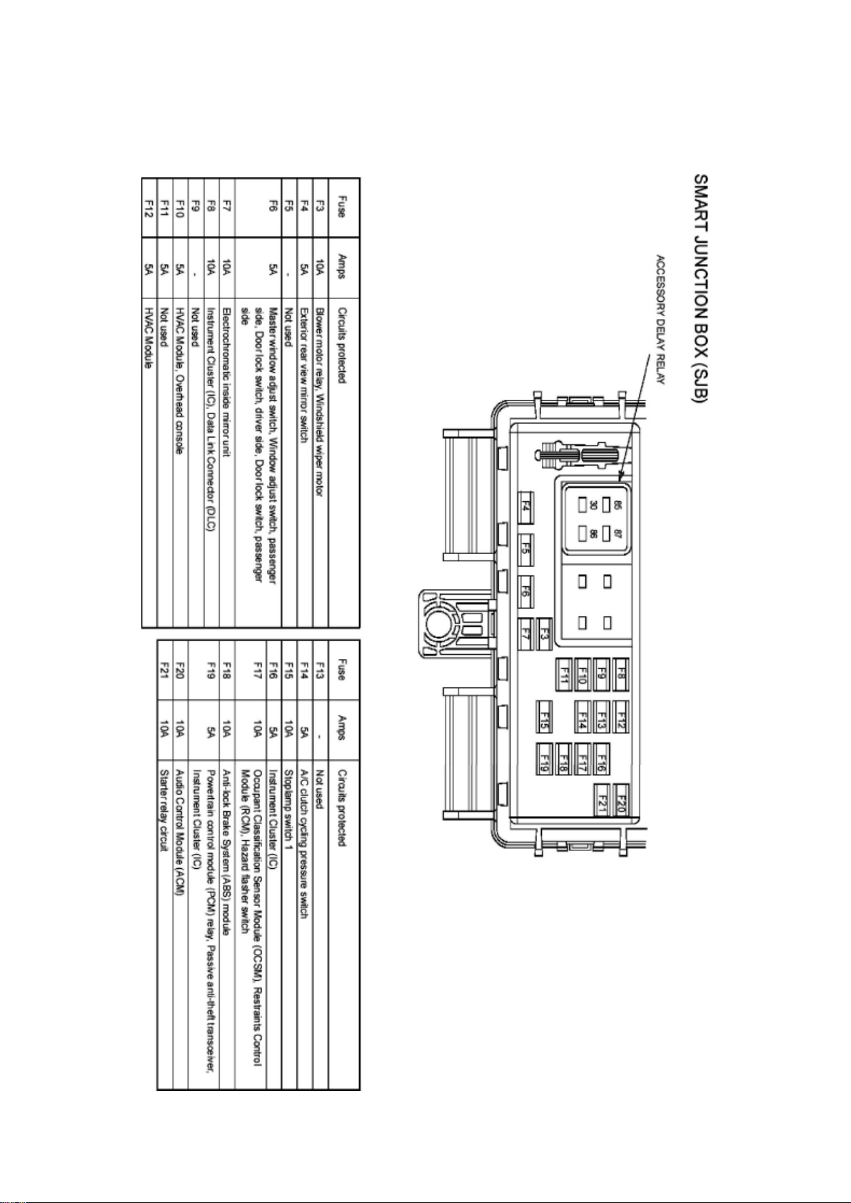
Ford Mustang Workshop Manual (V6-4.0L (2008))
Ford Workshop Manuals > Relays and Modules > Relays and Modules - Accessories and Optional Equipment > Accessory
Delay Module > Accessory Delay Relay > Component Information > Locations
Page 3

Page 4

Ford Mustang Workshop Manual (V6-4.0L (2008))
Ford Workshop Manuals > Relays and Modules > Relays and Modules - Accessories and Optional Equipment >
Communications Control Module > Component Information > Technical Service Bulletins > Customer Interest for
Communications Control Module: > 10-2-8 > Feb > 10 > SYNC(R) System - Defaults To 'Privacy Mode'
Communications Control Module: Customer Interest SYNC(R) System - Defaults To 'Privacy Mode'
TSB 10-2-8
02/15/10
SYNC SYSTEM DEFAULTS TO OR STAYS IN PRIVACY MODE, MULTIPLE VEHICLE LINES
FORD: 2008-2009 Taurus X 2008-2010 Focus, Fusion, Mustang, Taurus, Edge, Escape,
Expedition, Explorer Sport Trac, Explorer, F-150, F-250, F-350, F-450 2009-2010 Flex
LINCOLN: 2008-2010 MKZ 2009-2010 MKS 2008 Mark LT 2008-2010 MKX, Navigator 2010 MKT
MERCURY: 2008-2009 Sable 2008-2010 Milan, Mariner, Mountaineer
ISSUE Some customers of 2008-2010 SYNC-equipped vehicles may express concern with their
SYNC paired device defaulting, switching or staying on privacy mode. The customer may not be
able to accept the call through the SYNC system or must answer the call manually on their
personal device.
ACTION Follow the Service Procedure steps to correct the condition.
SERVICE PROCEDURE
1. Set the Privacy mode to Off on the device and recheck Sync operation.
2. If necessary, test the device on another vehicle with the same version SYNC. If the concern is
still present, the device is the concern. Continue with
normal WSM Diagnostics.
NOTE
PRIVACY MODE MEANS THAT THE PHONE IS CONTROLLING THE AUDIO. SYNC ONLY
MAKES REQUESTS TO THE PHONE TO TRANSFER THIS RESPONSIBILITY OR AUDIO TO
SYNC. IF THE PHONE DOES NOT ACCEPT THIS REQUEST OR THERE IS A PROBLEM IN
THE COMMUNICATION TO MAKE THIS HAPPEN, YOU ARE BY DEFAULT IN PRIVACY MODE.
WARRANTY STATUS: Information Only
Disclaimer
Page 5

Ford Mustang Workshop Manual (V6-4.0L (2008))
Ford Workshop Manuals > Relays and Modules > Relays and Modules - Accessories and Optional Equipment >
Communications Control Module > Component Information > Technical Service Bulletins > All Technical Service Bulletins
for Communications Control Module: > 10-2-8 > Feb > 10 > SYNC(R) System - Defaults To 'Privacy Mode'
Communications Control Module: All Technical Service Bulletins SYNC(R) System - Defaults To
'Privacy Mode'
TSB 10-2-8
02/15/10
SYNC SYSTEM DEFAULTS TO OR STAYS IN PRIVACY MODE, MULTIPLE VEHICLE LINES
FORD: 2008-2009 Taurus X 2008-2010 Focus, Fusion, Mustang, Taurus, Edge, Escape,
Expedition, Explorer Sport Trac, Explorer, F-150, F-250, F-350, F-450 2009-2010 Flex
LINCOLN: 2008-2010 MKZ 2009-2010 MKS 2008 Mark LT 2008-2010 MKX, Navigator 2010 MKT
MERCURY: 2008-2009 Sable 2008-2010 Milan, Mariner, Mountaineer
ISSUE Some customers of 2008-2010 SYNC-equipped vehicles may express concern with their
SYNC paired device defaulting, switching or staying on privacy mode. The customer may not be
able to accept the call through the SYNC system or must answer the call manually on their
personal device.
ACTION Follow the Service Procedure steps to correct the condition.
SERVICE PROCEDURE
1. Set the Privacy mode to Off on the device and recheck Sync operation.
2. If necessary, test the device on another vehicle with the same version SYNC. If the concern is
still present, the device is the concern. Continue with
normal WSM Diagnostics.
NOTE
PRIVACY MODE MEANS THAT THE PHONE IS CONTROLLING THE AUDIO. SYNC ONLY
MAKES REQUESTS TO THE PHONE TO TRANSFER THIS RESPONSIBILITY OR AUDIO TO
SYNC. IF THE PHONE DOES NOT ACCEPT THIS REQUEST OR THERE IS A PROBLEM IN
THE COMMUNICATION TO MAKE THIS HAPPEN, YOU ARE BY DEFAULT IN PRIVACY MODE.
WARRANTY STATUS: Information Only
Disclaimer
Page 6
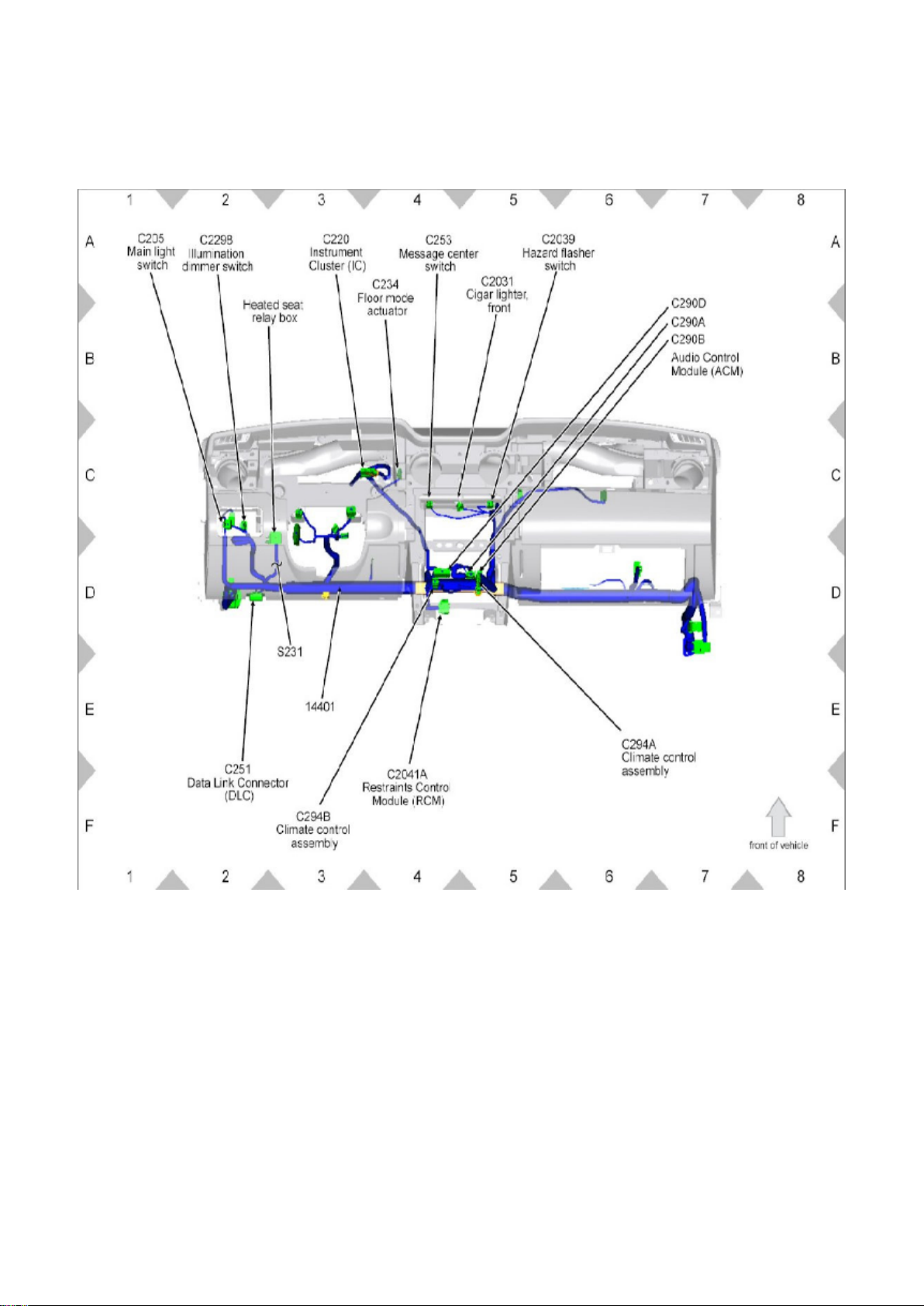
Ford Mustang Workshop Manual (V6-4.0L (2008))
Ford Workshop Manuals > Relays and Modules > Relays and Modules - Accessories and Optional Equipment >
Communications Control Module > Component Information > Technical Service Bulletins > Page 21
View 151-14
Page 7
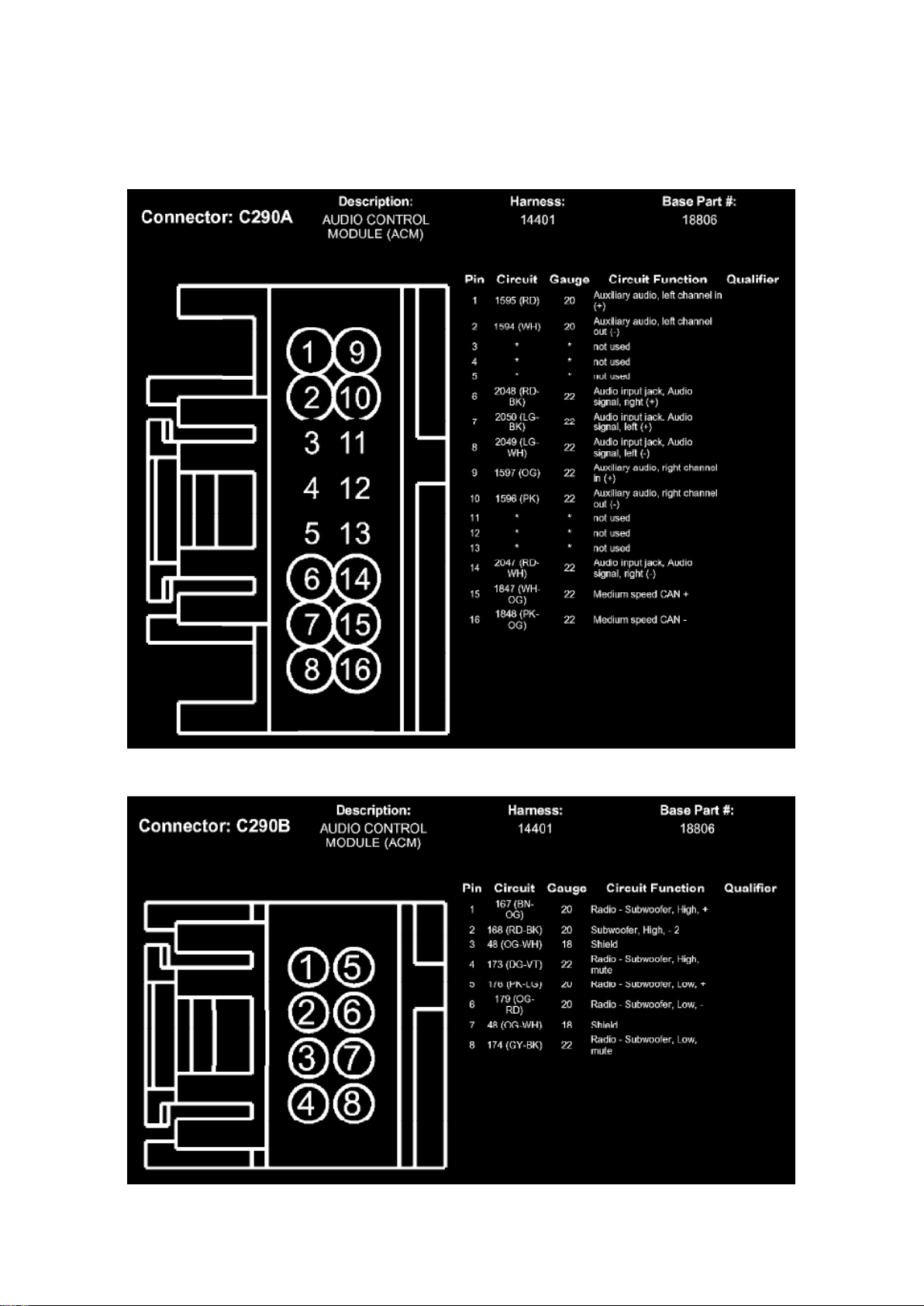
Ford Mustang Workshop Manual (V6-4.0L (2008))
Ford Workshop Manuals > Relays and Modules > Relays and Modules - Accessories and Optional Equipment >
Communications Control Module > Component Information > Technical Service Bulletins > Page 22
Page 8

Communications Control Module: Diagrams
C290A
Page 9
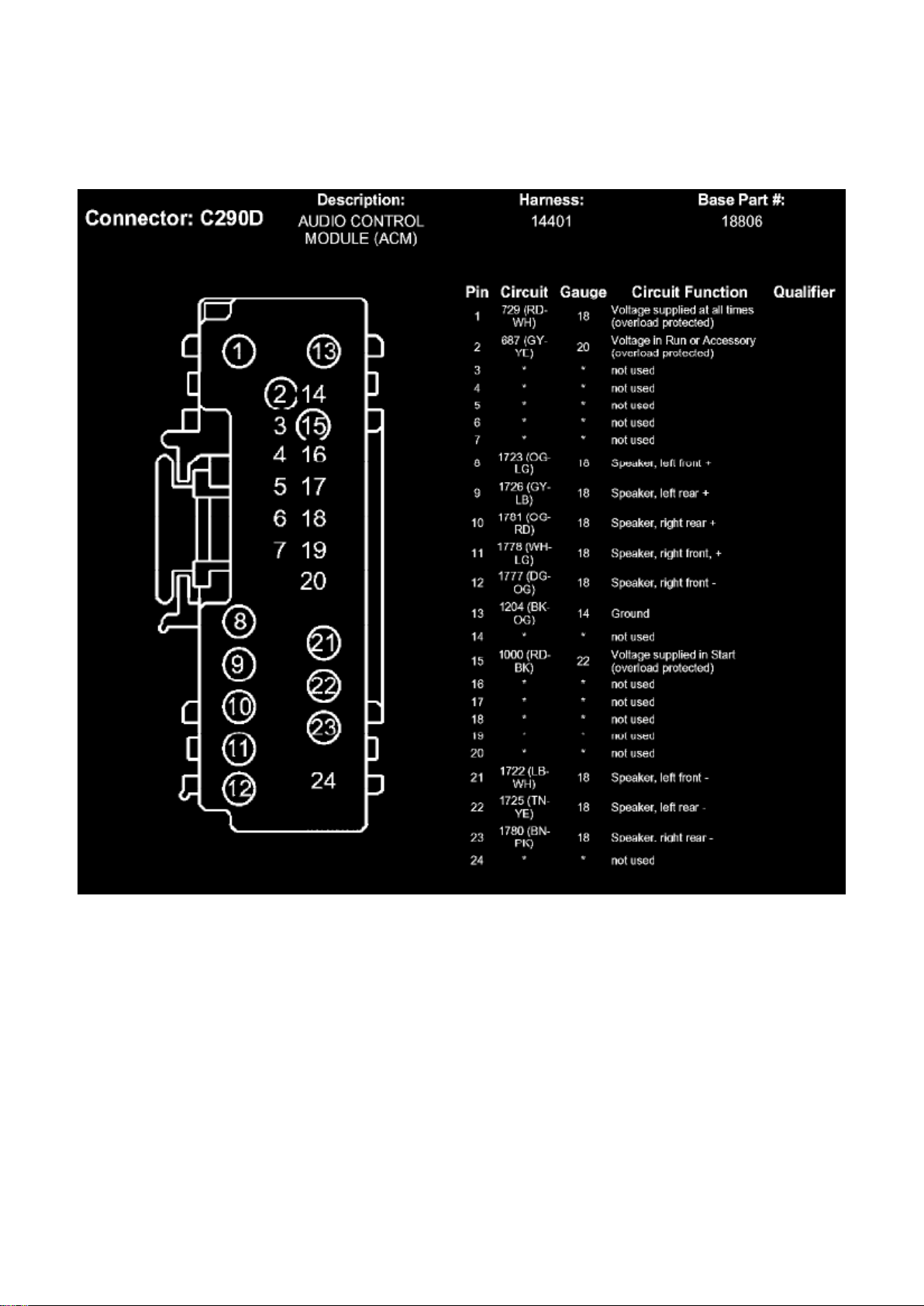
Ford Mustang Workshop Manual (V6-4.0L (2008))
Ford Workshop Manuals > Relays and Modules > Relays and Modules - Accessories and Optional Equipment >
Communications Control Module > Component Information > Technical Service Bulletins > Page 23
C290B
C290D
Page 10
Ford Mustang Workshop Manual (V6-4.0L (2008))
Ford Workshop Manuals > Relays and Modules > Relays and Modules - Accessories and Optional Equipment >
Communications Control Module > Component Information > Technical Service Bulletins > Page 24
Communications Control Module: Service and Repair
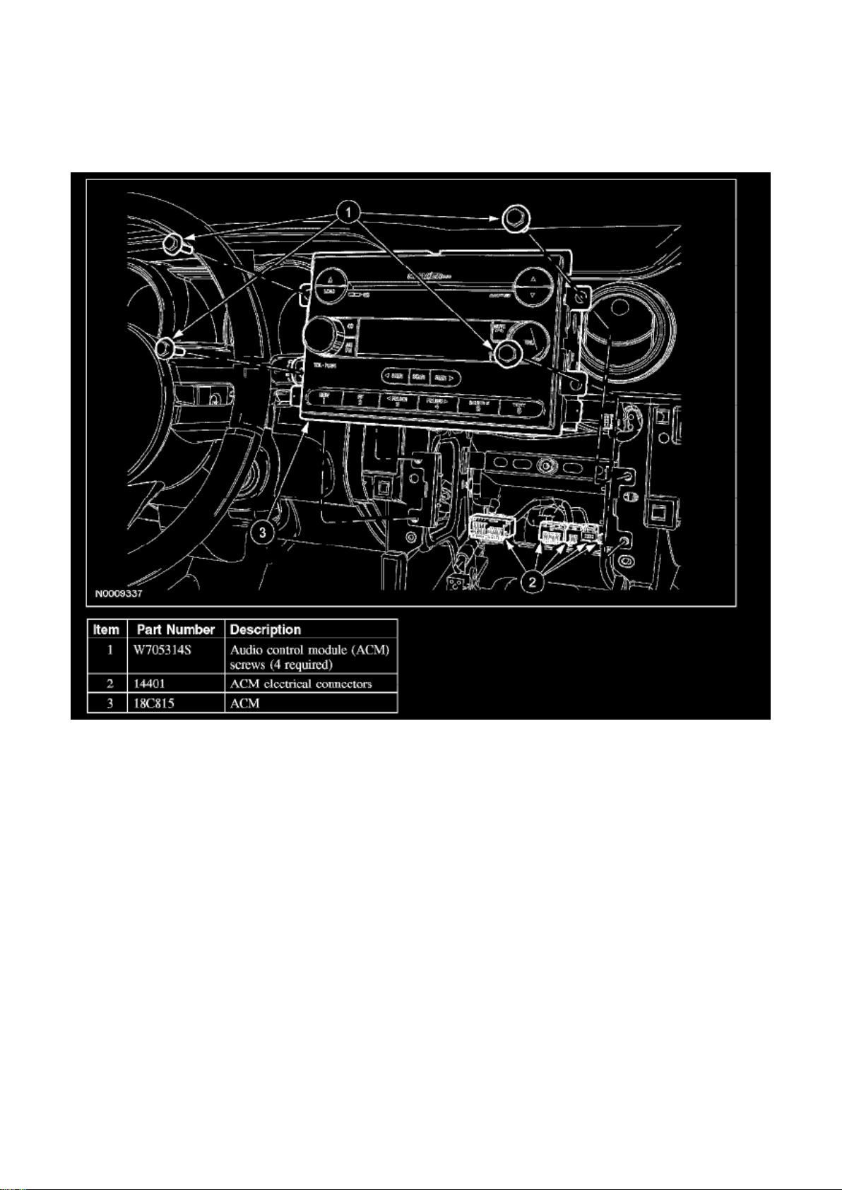
AUDIO CONTROL MODULE (ACM)
Removal and Installation
NOTE:
- It is not necessary to remove the audio control module (ACM) to retrieve the part number.
- If installing a new navigation ACM, remove the navigation DVD, if possible, before sending the
ACM to an authorized audio system repair facility.
1. NOTE: Module configuration is only required if a new ACM is being installed.
Upload the ACM configuration information to the scan tool.
2. Remove the instrument panel center finish panel. 3. Remove the 4 screws and the ACM.
- Disconnect the electrical connectors and the antenna lead-in cable.
Page 11

4. To install, reverse the removal procedure.
- Download the configuration information to the ACM.
Page 12
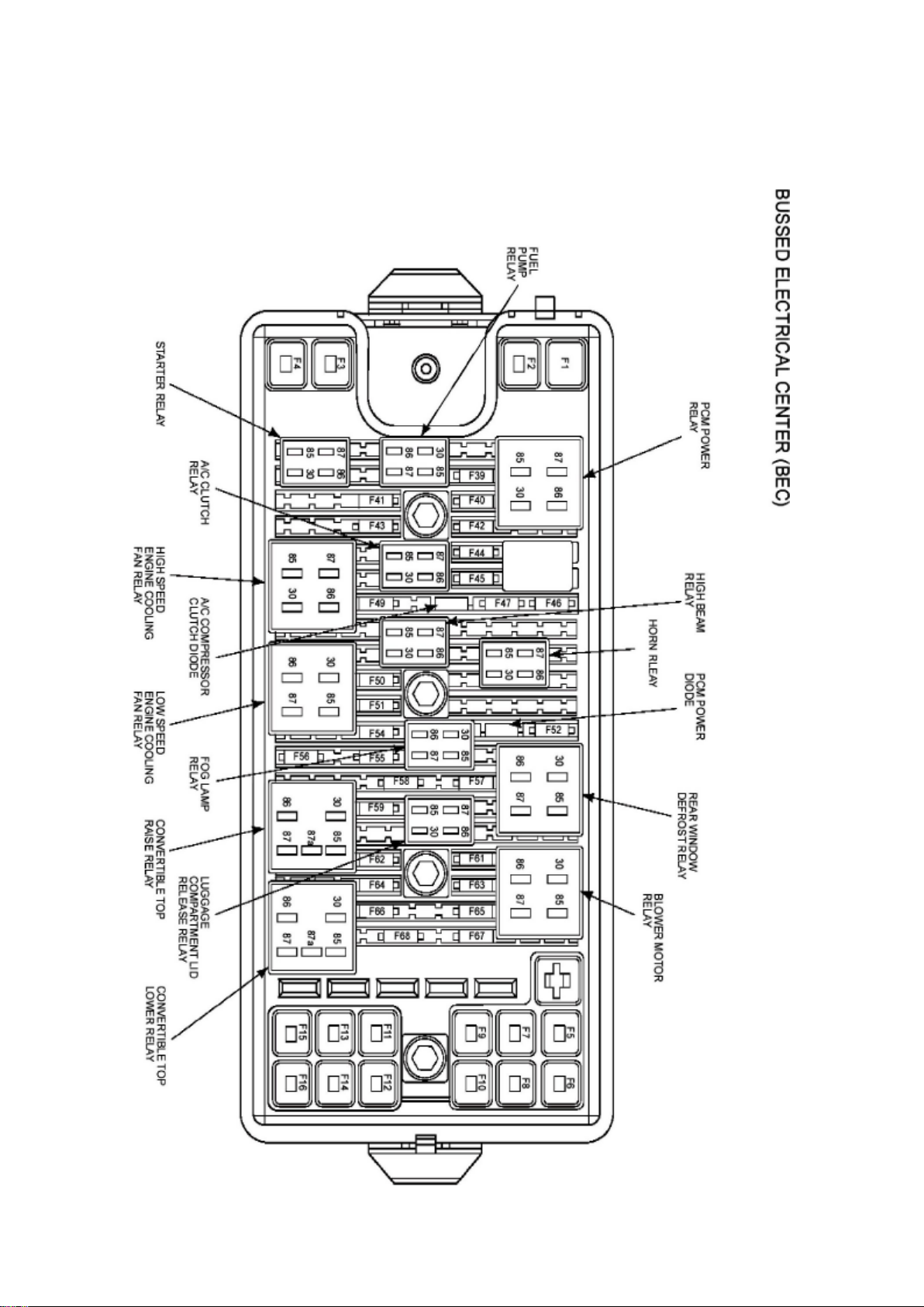
Ford Mustang Workshop Manual (V6-4.0L (2008))
Ford Workshop Manuals > Relays and Modules > Relays and Modules - Body and Frame > Convertible Top Relay >
Component Information > Locations > Convertible Top Raise Relay
Page 13

Page 14
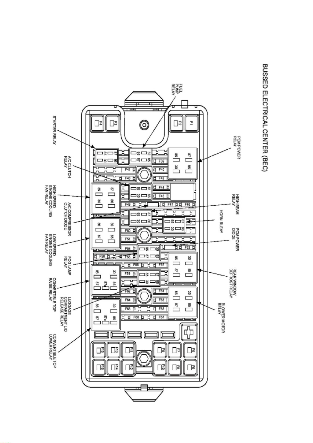
Ford Mustang Workshop Manual (V6-4.0L (2008))
Ford Workshop Manuals > Relays and Modules > Relays and Modules - Body and Frame > Convertible Top Relay >
Component Information > Locations > Convertible Top Raise Relay > Page 30
Page 15

Page 16
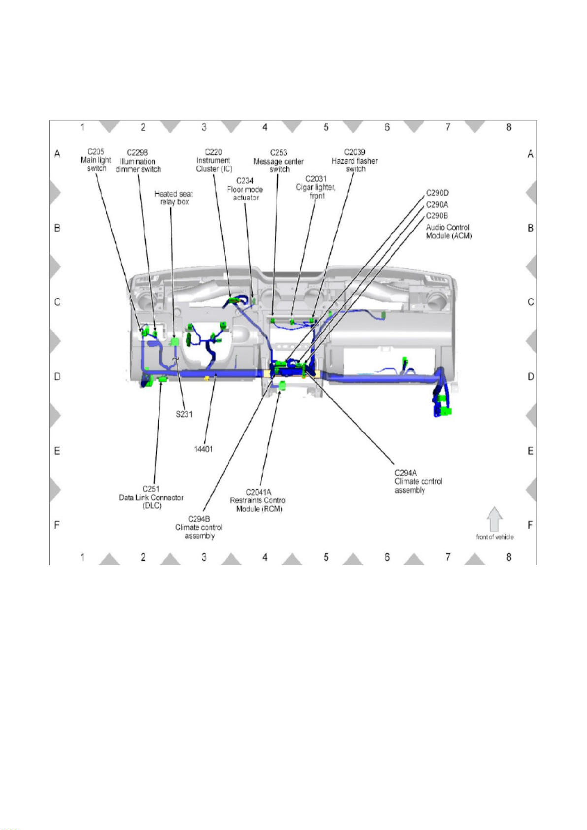
Ford Mustang Workshop Manual (V6-4.0L (2008))
Ford Workshop Manuals > Relays and Modules > Relays and Modules - Body and Frame > Seat Heater Relay >
Component Information > Locations > Heated Seat Relay Box
View 151-14
Page 17
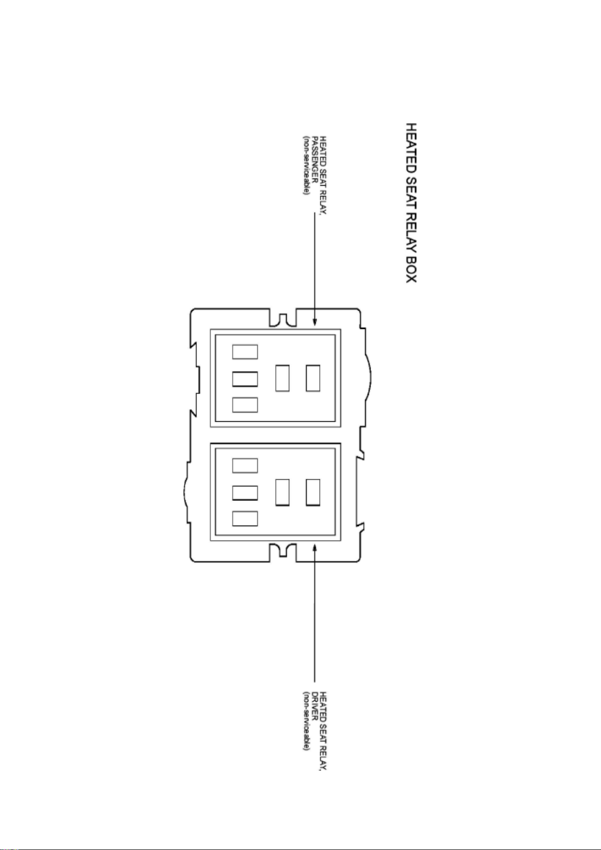
Ford Mustang Workshop Manual (V6-4.0L (2008))
Ford Workshop Manuals > Relays and Modules > Relays and Modules - Body and Frame > Seat Heater Relay >
Component Information > Locations > Heated Seat Relay Box > Page 35
Page 18

Seat Heater Relay: Locations Heated Seat Relay
Page 19
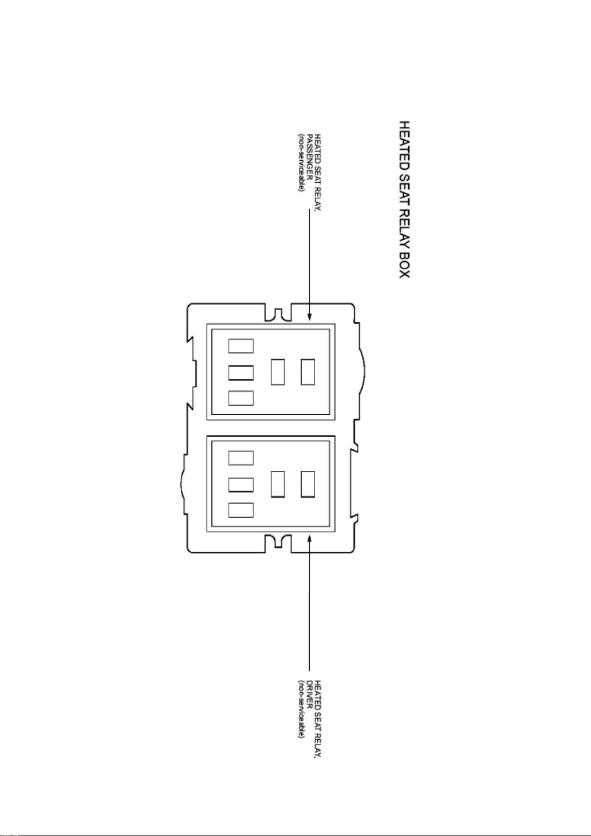
Ford Mustang Workshop Manual (V6-4.0L (2008))
Ford Workshop Manuals > Relays and Modules > Relays and Modules - Body and Frame > Seat Heater Relay >
Component Information > Locations > Heated Seat Relay Box > Page 36
Page 20

Page 21
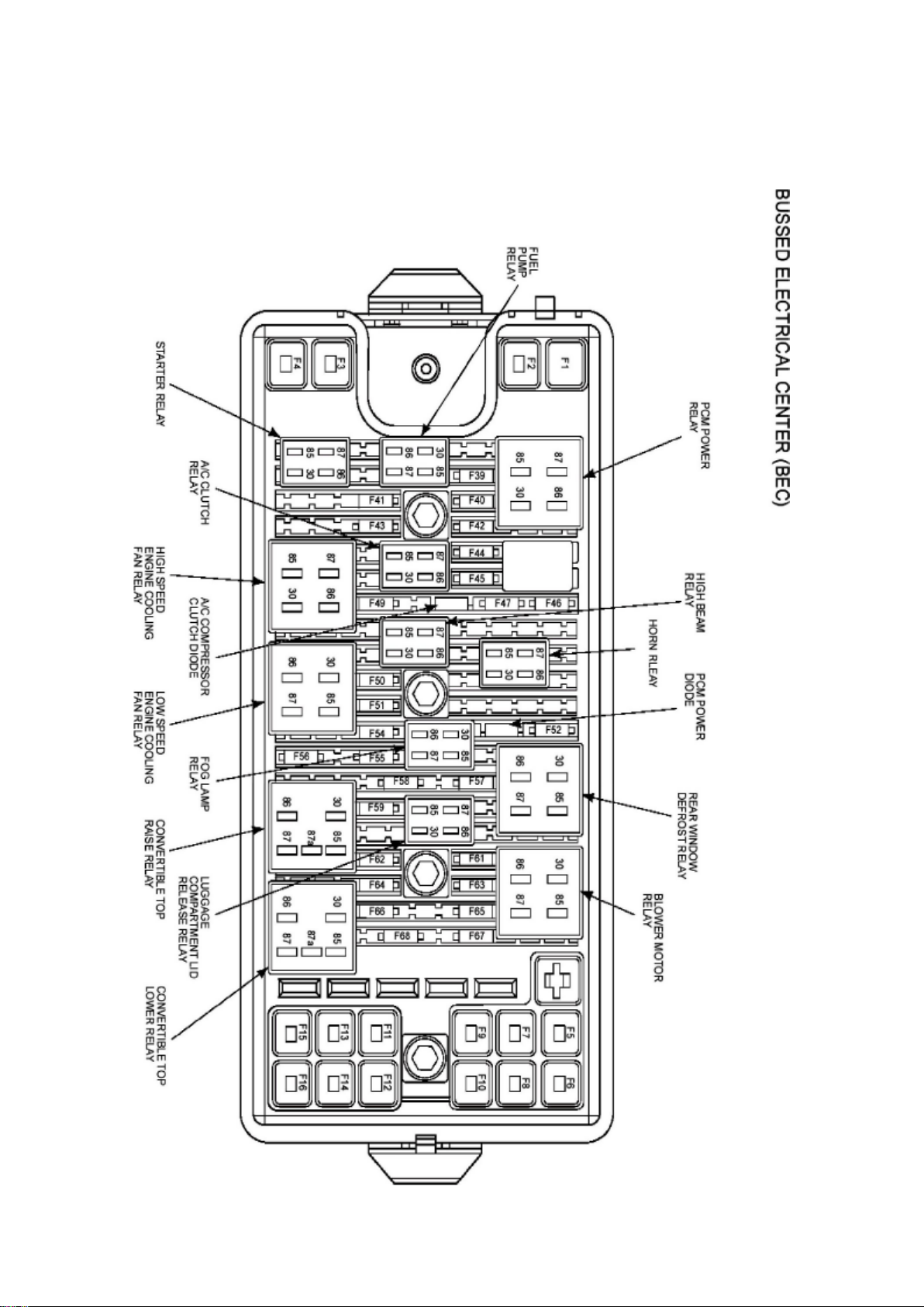
Ford Mustang Workshop Manual (V6-4.0L (2008))
Ford Workshop Manuals > Relays and Modules > Relays and Modules - Body and Frame > Trunk / Liftgate Relay >
Component Information > Locations
Page 22

Page 23
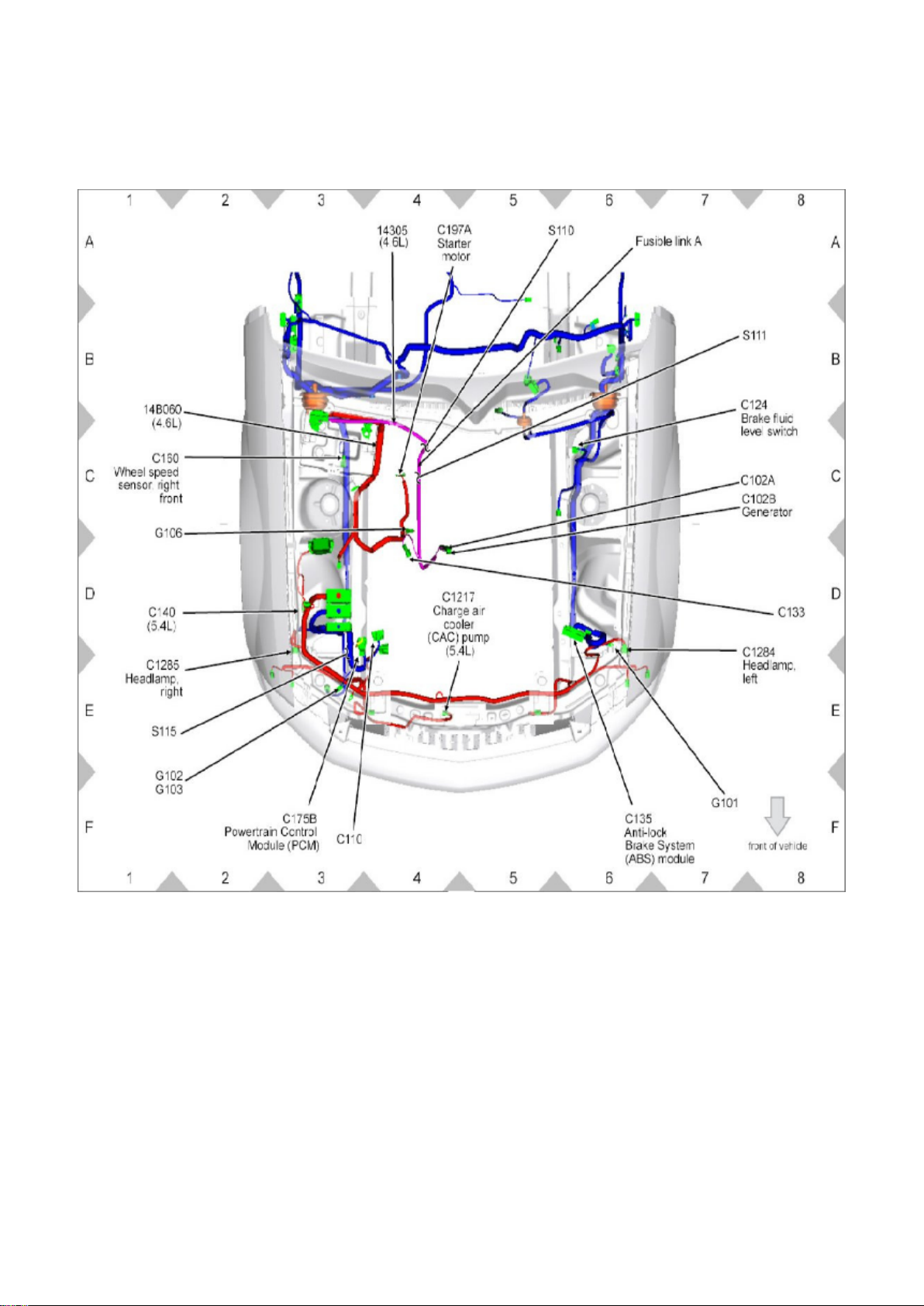
Ford Mustang Workshop Manual (V6-4.0L (2008))
Ford Workshop Manuals > Relays and Modules > Relays and Modules - Brakes and Traction Control > Electronic Brake
Control Module > Component Information > Locations
View 151-2
Page 24
Ford Mustang Workshop Manual (V6-4.0L (2008))
Ford Workshop Manuals > Relays and Modules > Relays and Modules - Brakes and Traction Control > Electronic Brake
Control Module > Component Information > Locations > Page 44
Page 25

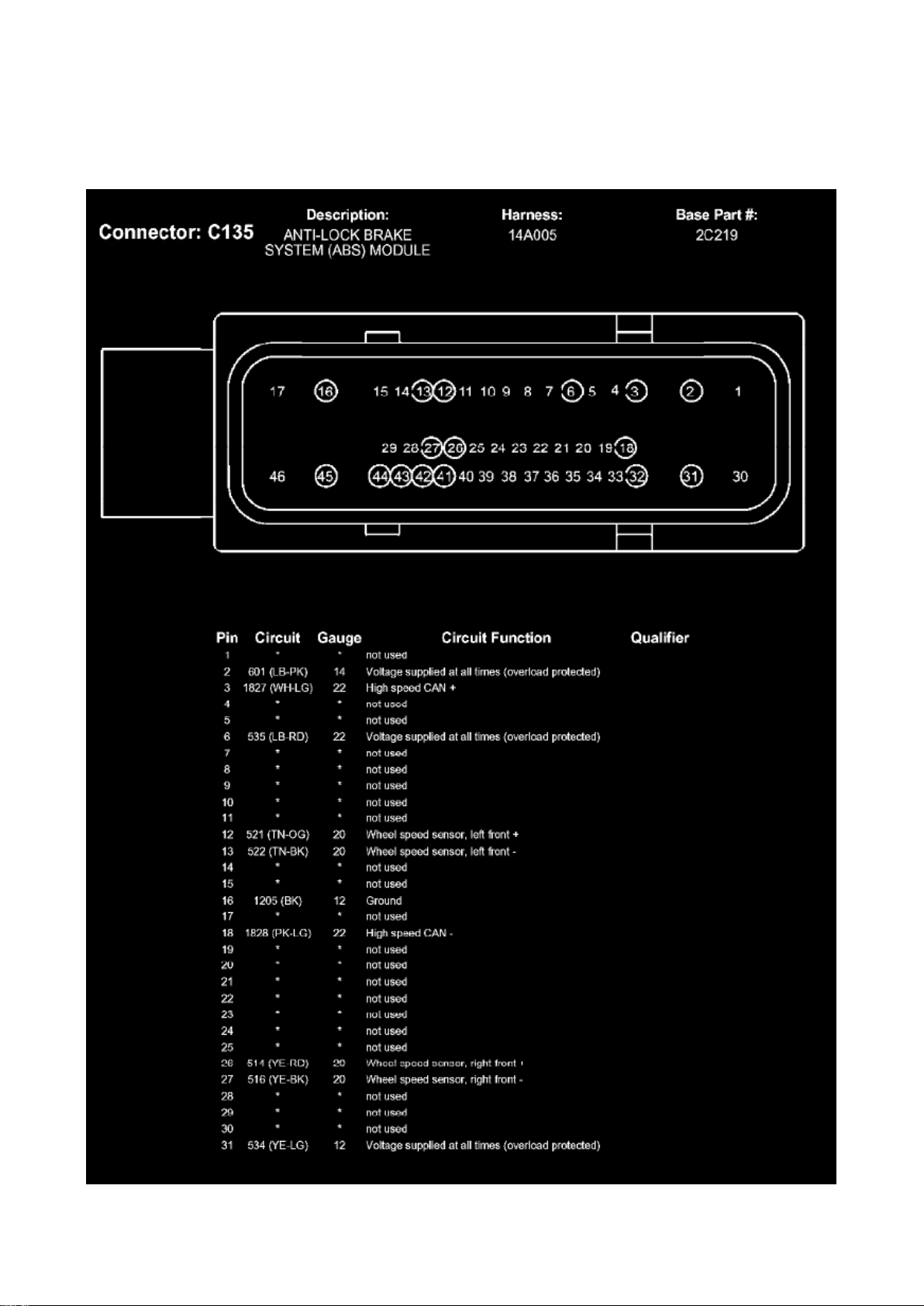
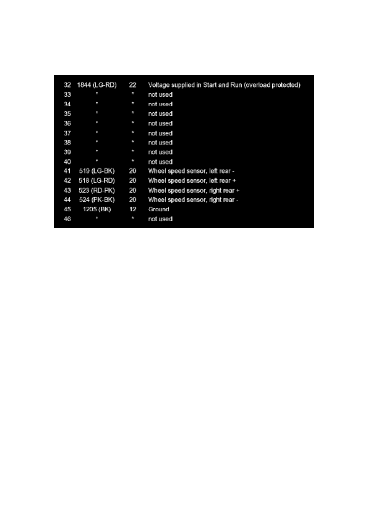
Electronic Brake Control Module: Diagrams
C135 (Part 1)
Page 26
Ford Mustang Workshop Manual (V6-4.0L (2008))
Ford Workshop Manuals > Relays and Modules > Relays and Modules - Brakes and Traction Control > Electronic Brake
Control Module > Component Information > Locations > Page 45
C135 (Part 2)
Page 27
Ford Mustang Workshop Manual (V6-4.0L (2008))
Ford Workshop Manuals > Relays and Modules > Relays and Modules - Brakes and Traction Control > Electronic Brake
Control Module > Component Information > Locations > Page 46
Electronic Brake Control Module: Service and Repair
Page 28

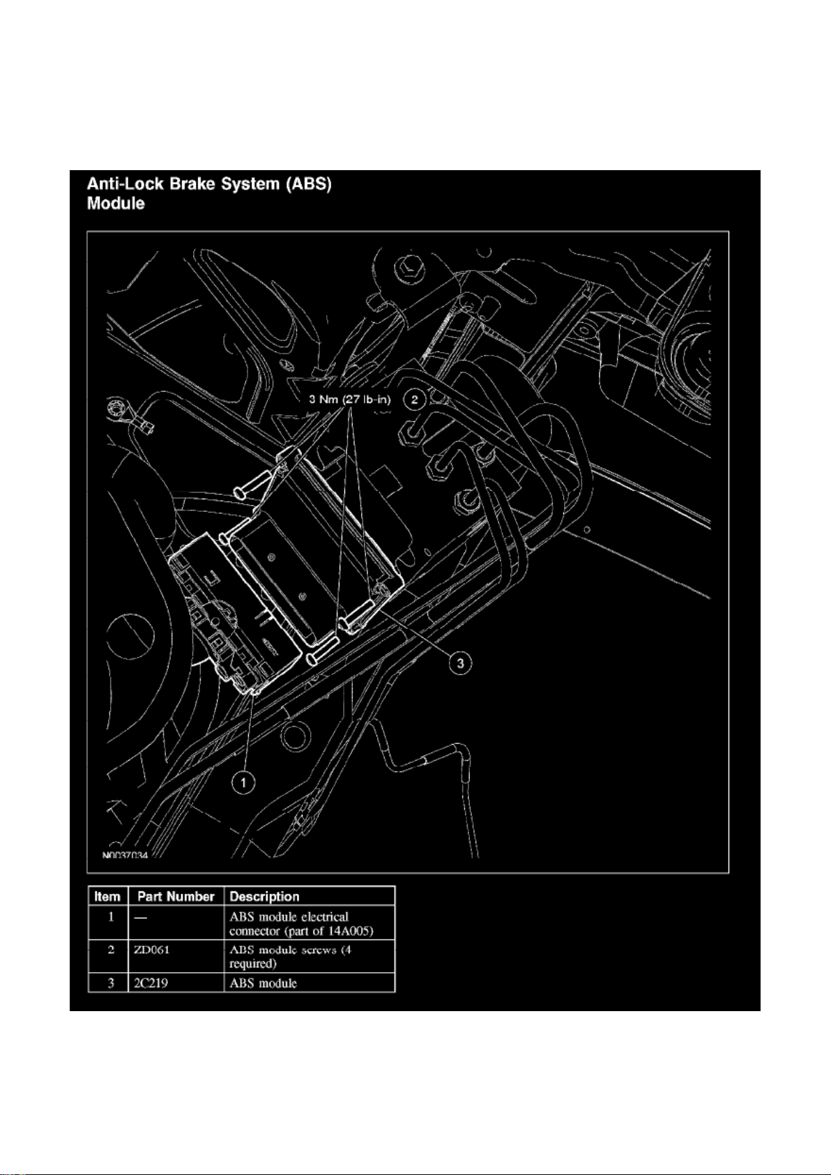
Anti-Lock Brake System (ABS) Module
Removal and Installation
CAUTION: Electronic modules are sensitive to electrical charges. The anti-lock brake system
(ABS) module can be damaged if exposed to these charges.
1. Disconnect the battery ground cable. For additional information, refer to Battery. 2. Remove the
air cleaner assembly. For additional information, refer to Fuel Delivery and Air Induction. 3.
Disconnect the ABS module electrical connector.
Page 29
Ford Mustang Workshop Manual (V6-4.0L (2008))
Ford Workshop Manuals > Relays and Modules > Relays and Modules - Brakes and Traction Control > Electronic Brake
Control Module > Component Information > Locations > Page 47
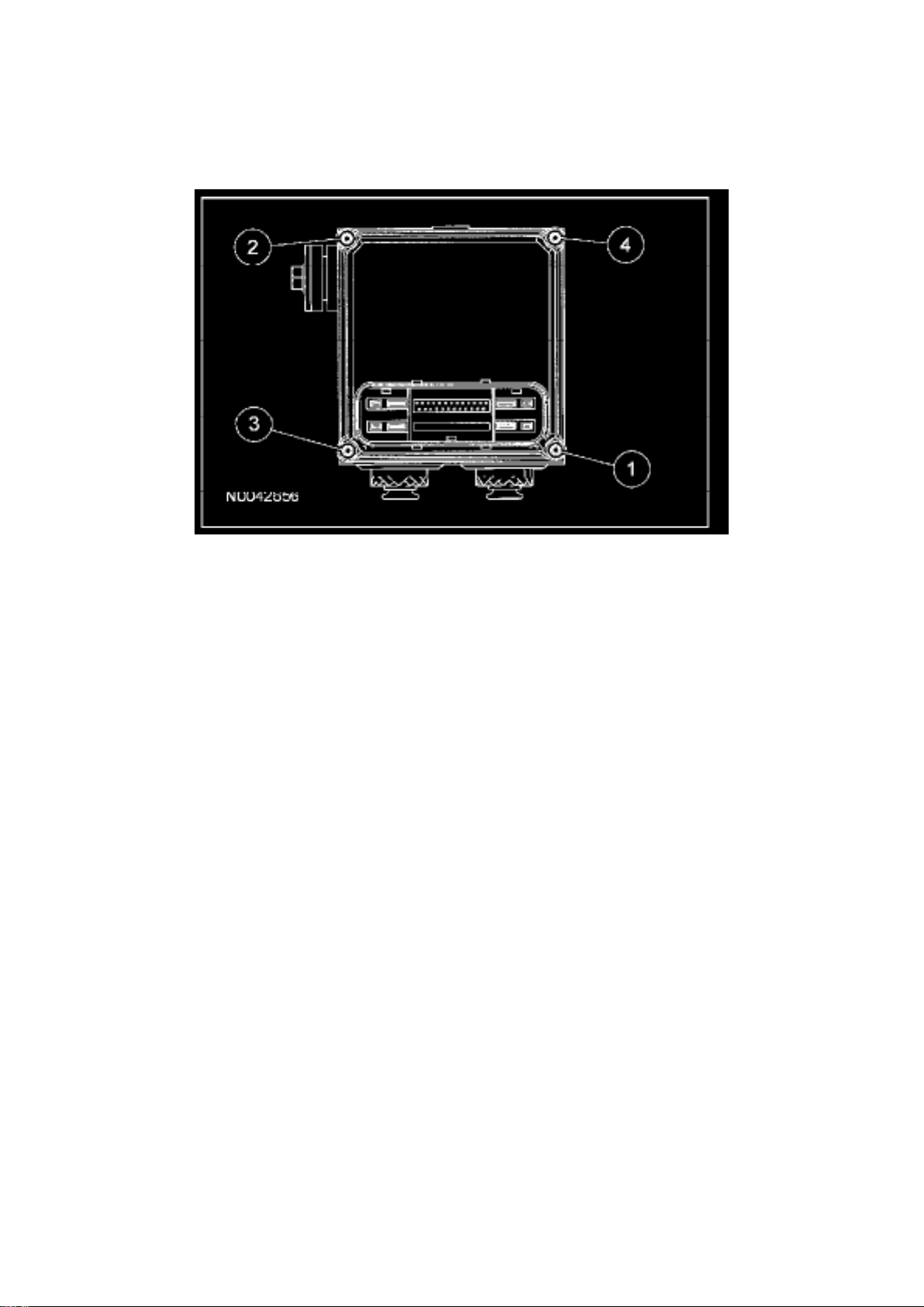
4. Remove the 4 screws and the ABS module.
^ To install, tighten to 3 Nm (27 lb-in) in the sequence shown.
5. To install, reverse the removal procedure.
Page 30
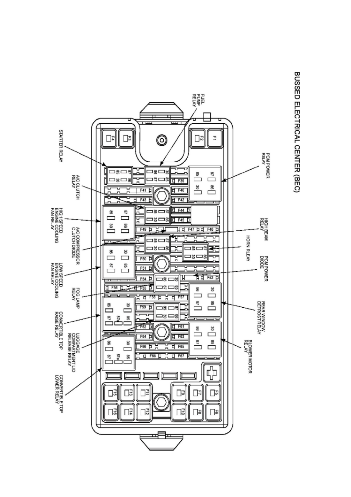
Ford Mustang Workshop Manual (V6-4.0L (2008))
Ford Workshop Manuals > Relays and Modules > Relays and Modules - Cooling System > Radiator Cooling Fan Motor
Relay > Component Information > Locations > High Speed Engine Cooling Fan Relay
Page 31

Page 32
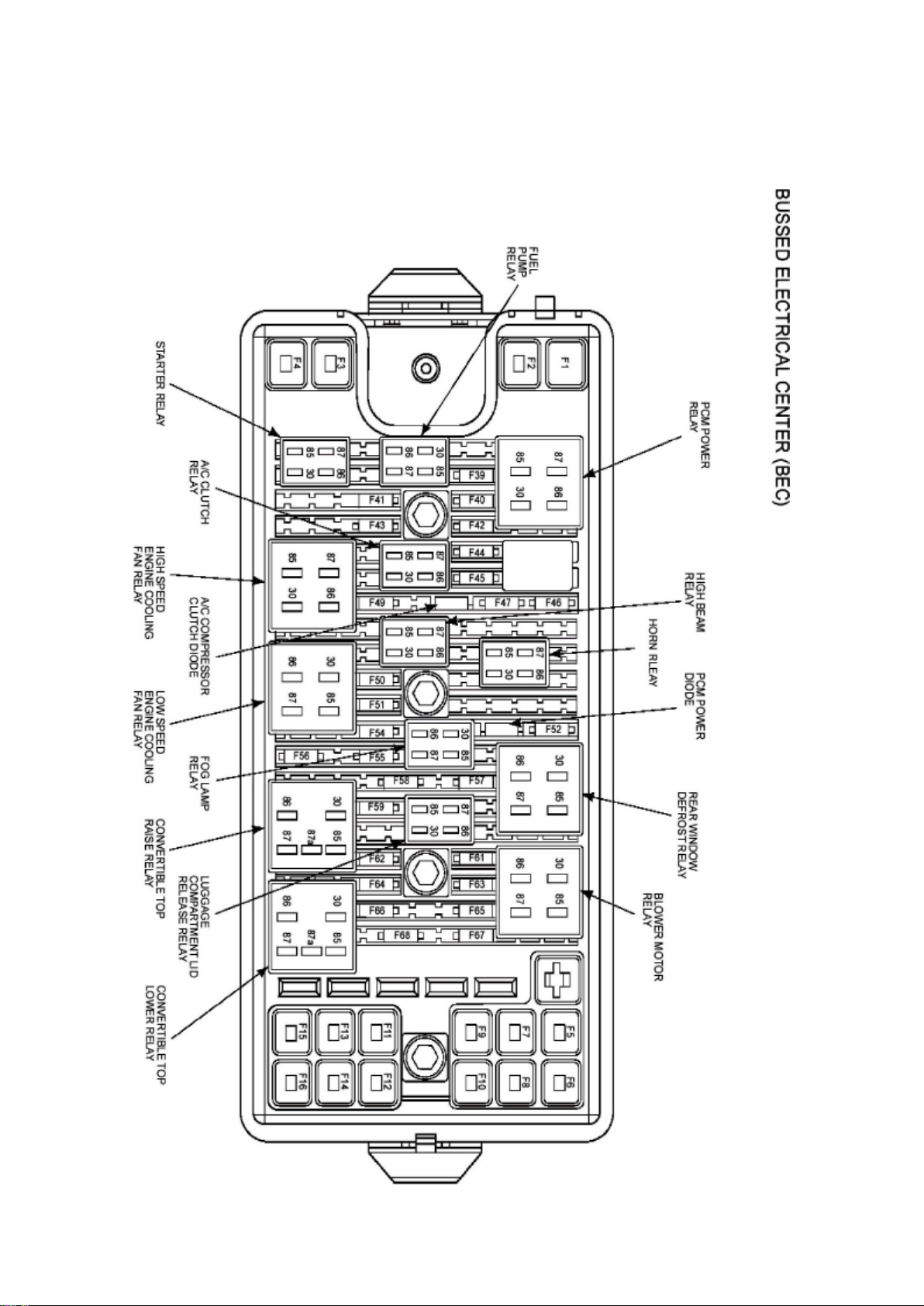
Ford Mustang Workshop Manual (V6-4.0L (2008))
Ford Workshop Manuals > Relays and Modules > Relays and Modules - Cooling System > Radiator Cooling Fan Motor
Relay > Component Information > Locations > High Speed Engine Cooling Fan Relay > Page 53
Page 33

Page 34
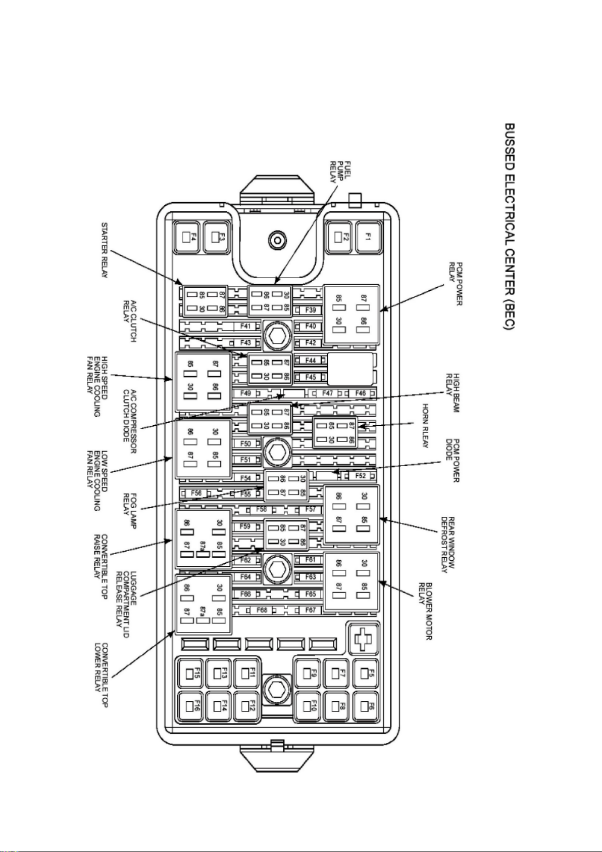
Ford Mustang Workshop Manual (V6-4.0L (2008))
Ford Workshop Manuals > Relays and Modules > Relays and Modules - HVAC > Blower Motor Relay > Component
Information > Locations
Page 35

Page 36
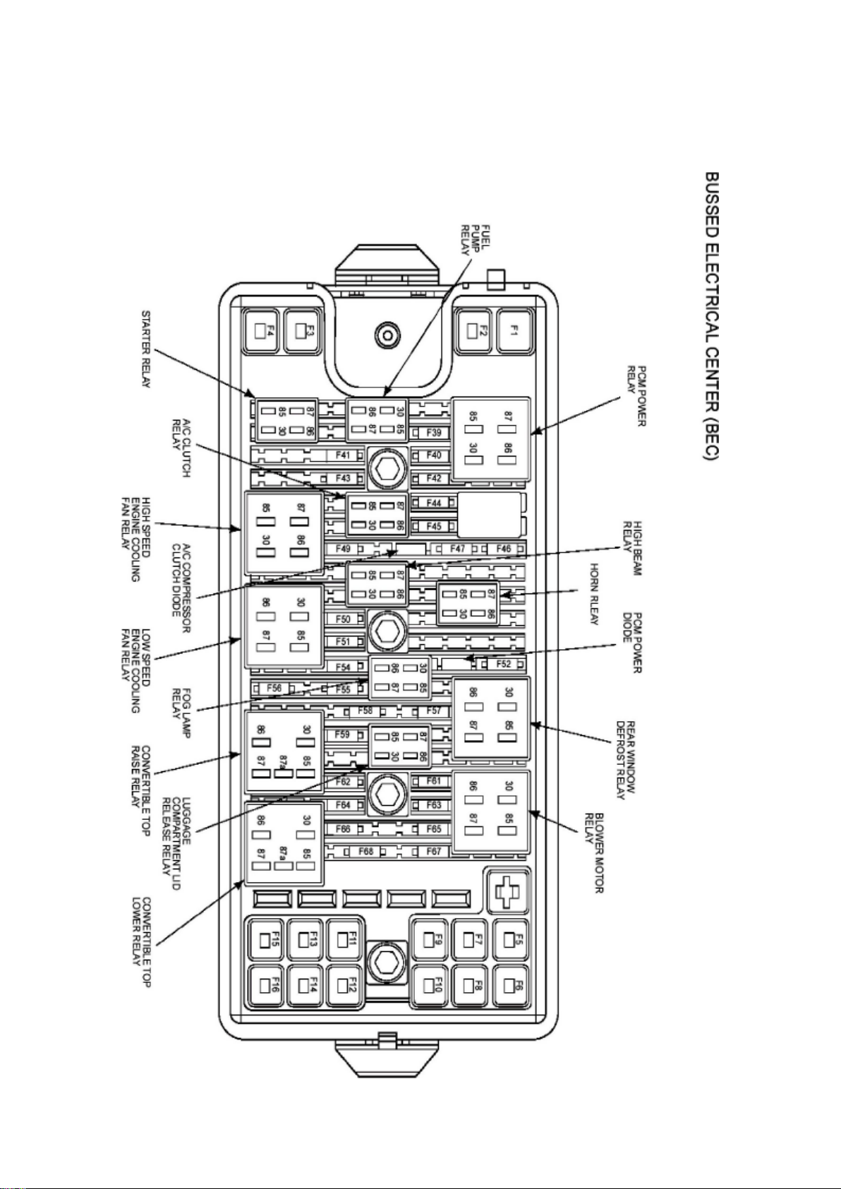
Ford Mustang Workshop Manual (V6-4.0L (2008))
Ford Workshop Manuals > Relays and Modules > Relays and Modules - HVAC > Compressor Clutch Relay > Component
Information > Locations
Page 37

Page 38

Ford Mustang Workshop Manual (V6-4.0L (2008))
Ford Workshop Manuals > Relays and Modules > Relays and Modules - HVAC > Compressor Clutch Relay > Component
Information > Locations > Page 61
Page 39

Compressor Clutch Relay: Description and Operation
AIR CONDITIONING (A/C) CLUTCH RELAY (A/CCR)
NOTE: The PCM PIDs WAC and wide open throttle air conditioning cutoff fault (WACF) are used to
monitor the A/CCR output.
The A/CCR is wired normally open. There is no direct electrical connection between the A/C switch
or electronic automatic temperature control (EATC) module and the A/C clutch. The PCM receives
a signal indicating that A/C is requested. For some applications, this message is sent through the
communications network. When A/C is requested, the PCM checks other A/C related inputs that
are available, such as A/C pressure switch and A/C cycling switch. If these inputs indicate A/C
operation is OK, and the engine conditions are OK (coolant temperature, engine RPM, throttle
position), the PCM grounds the A/CCR output, closing the relay contacts and sending voltage to
the A/CCR.
Page 40
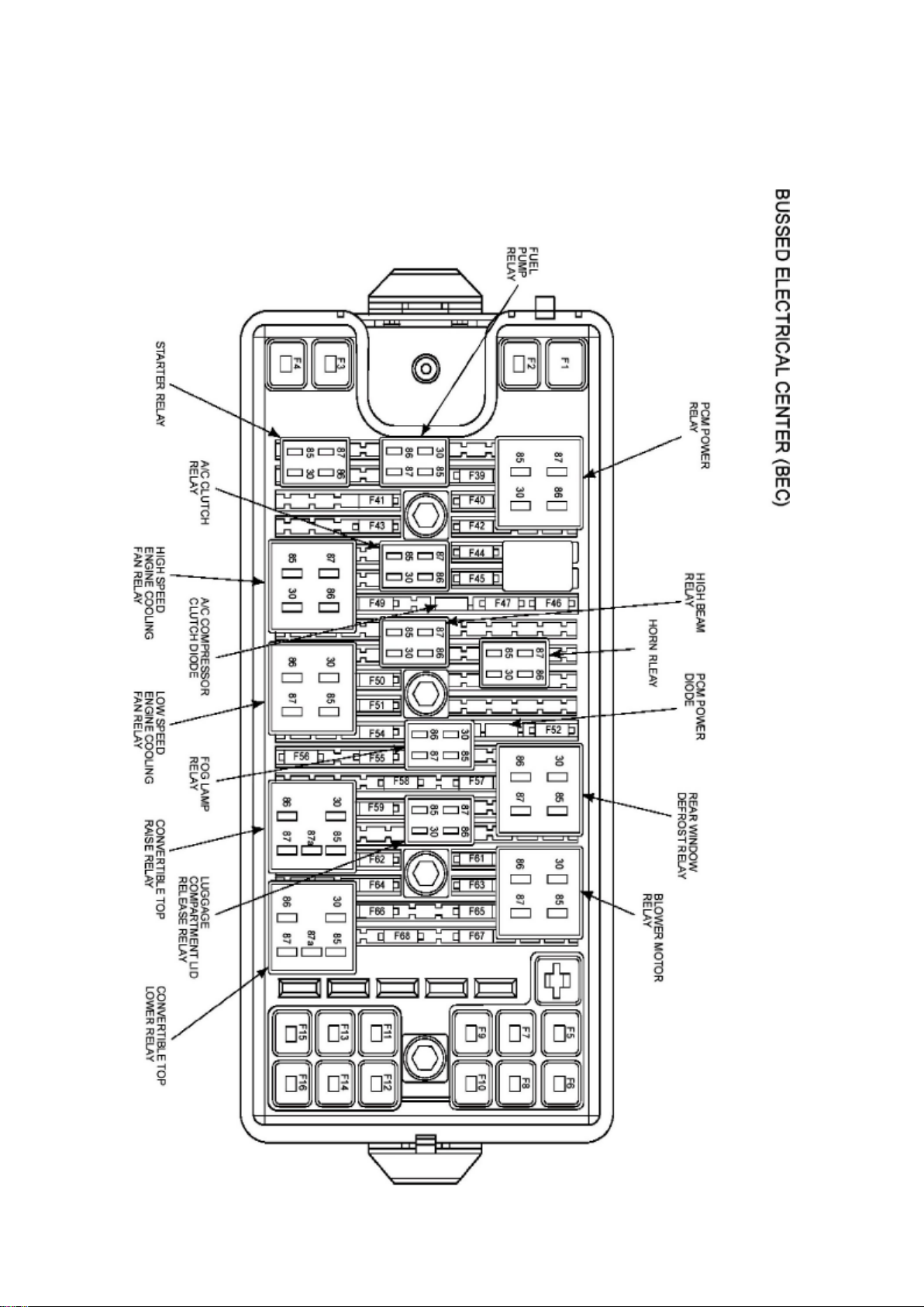
Ford Mustang Workshop Manual (V6-4.0L (2008))
Ford Workshop Manuals > Relays and Modules > Relays and Modules - Lighting and Horns > Fog/Driving Lamp Relay >
Component Information > Locations
Page 41

Page 42
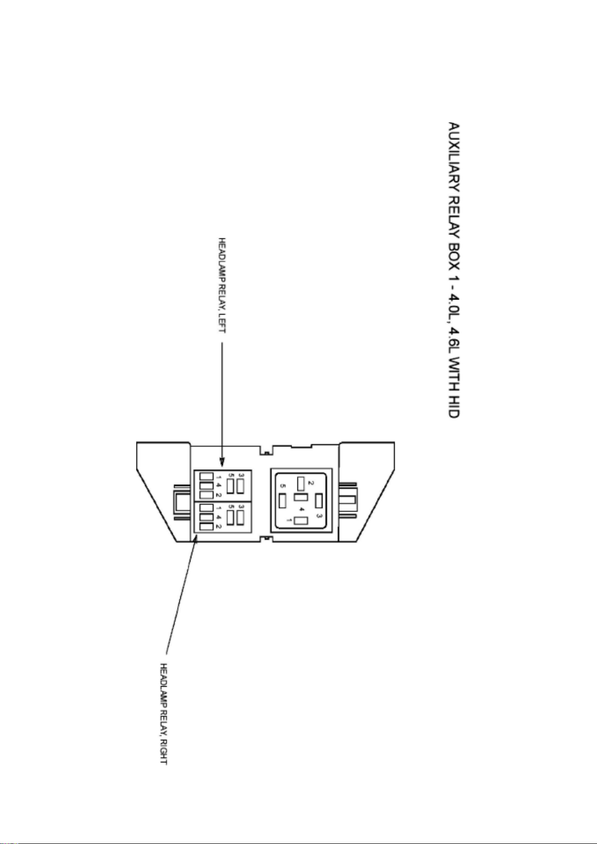
Ford Mustang Workshop Manual (V6-4.0L (2008))
Ford Workshop Manuals > Relays and Modules > Relays and Modules - Lighting and Horns > Headlamp Relay >
Component Information > Locations > Headlamp Relay, Left
Page 43

Page 44
Ford Mustang Workshop Manual (V6-4.0L (2008))
Ford Workshop Manuals > Relays and Modules > Relays and Modules - Lighting and Horns > Headlamp Relay >
Component Information > Locations > Headlamp Relay, Left > Page 70
Page 45

Page 46
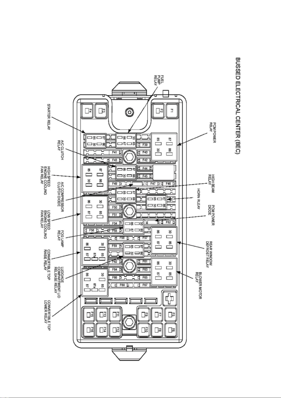
Ford Mustang Workshop Manual (V6-4.0L (2008))
Ford Workshop Manuals > Relays and Modules > Relays and Modules - Lighting and Horns > High Beam Relay >
Component Information > Locations
Page 47

Page 48
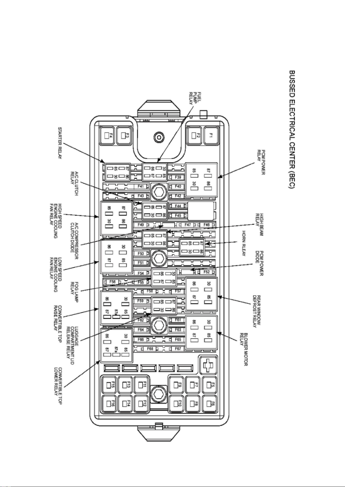
Ford Mustang Workshop Manual (V6-4.0L (2008))
Ford Workshop Manuals > Relays and Modules > Relays and Modules - Lighting and Horns > Horn Relay > Component
Information > Locations
Page 49

Page 50
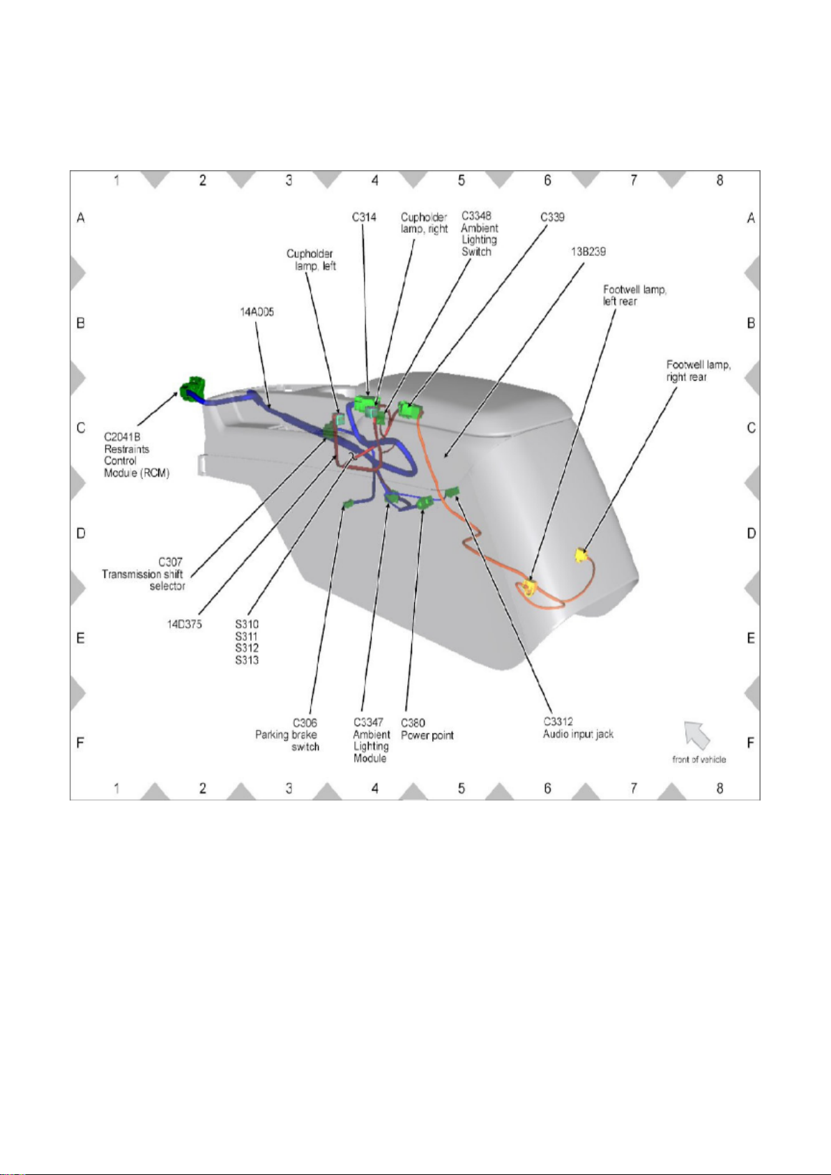
Ford Mustang Workshop Manual (V6-4.0L (2008))
Ford Workshop Manuals > Relays and Modules > Relays and Modules - Lighting and Horns > Interior Lighting Module >
Component Information > Locations
View 151-18
Page 51
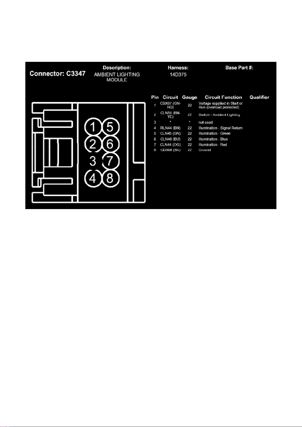
Ford Mustang Workshop Manual (V6-4.0L (2008))
Ford Workshop Manuals > Relays and Modules > Relays and Modules - Lighting and Horns > Interior Lighting Module >
Component Information > Locations > Page 80
C3347
Page 52
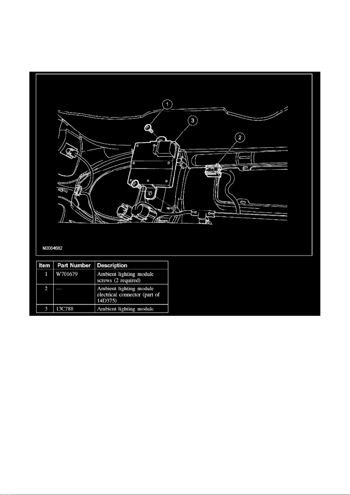
Ford Mustang Workshop Manual (V6-4.0L (2008))
Ford Workshop Manuals > Relays and Modules > Relays and Modules - Lighting and Horns > Interior Lighting Module >
Component Information > Locations > Page 81
Interior Lighting Module: Service and Repair
AMBIENT LIGHTING MODULE
Removal and Installation
1. Remove the floor console finish panel.
NOTE: The ambient lighting module is mounted under the bottom of the floor console finish panel
cup holder.
2. Remove the 2 screws and the ambient lighting module.
- Disconnect the electrical connector.
3. To install, reverse the removal procedure.
Page 53
Ford Mustang Workshop Manual (V6-4.0L (2008))
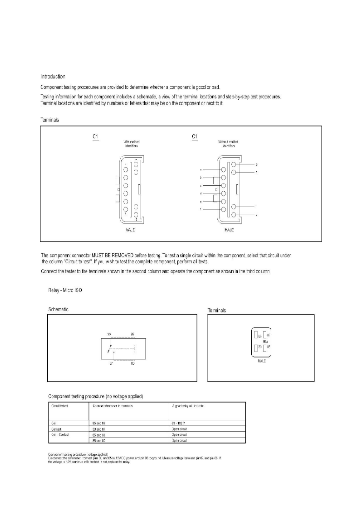
Ford Workshop Manuals > Relays and Modules > Relays and Modules - Power and Ground Distribution > Micro ISO Relay
> Component Information > Testing and Inspection
Page 54

Micro ISO Relay: Testing and Inspection
Page 55
Ford Mustang Workshop Manual (V6-4.0L (2008))
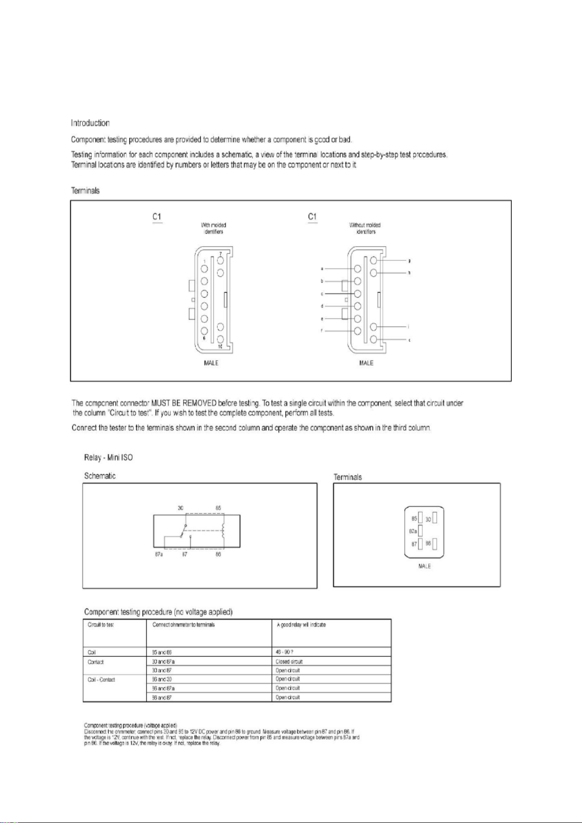
Ford Workshop Manuals > Relays and Modules > Relays and Modules - Power and Ground Distribution > Mini ISO Relay >
Component Information > Testing and Inspection
Page 56

Mini ISO Relay: Testing and Inspection
Page 57
Ford Mustang Workshop Manual (V6-4.0L (2008))
Ford Workshop Manuals > Relays and Modules > Relays and Modules - Power and Ground Distribution > Power
Distribution Module > Component Information > Service and Repair
Power Distribution Module: Service and Repair
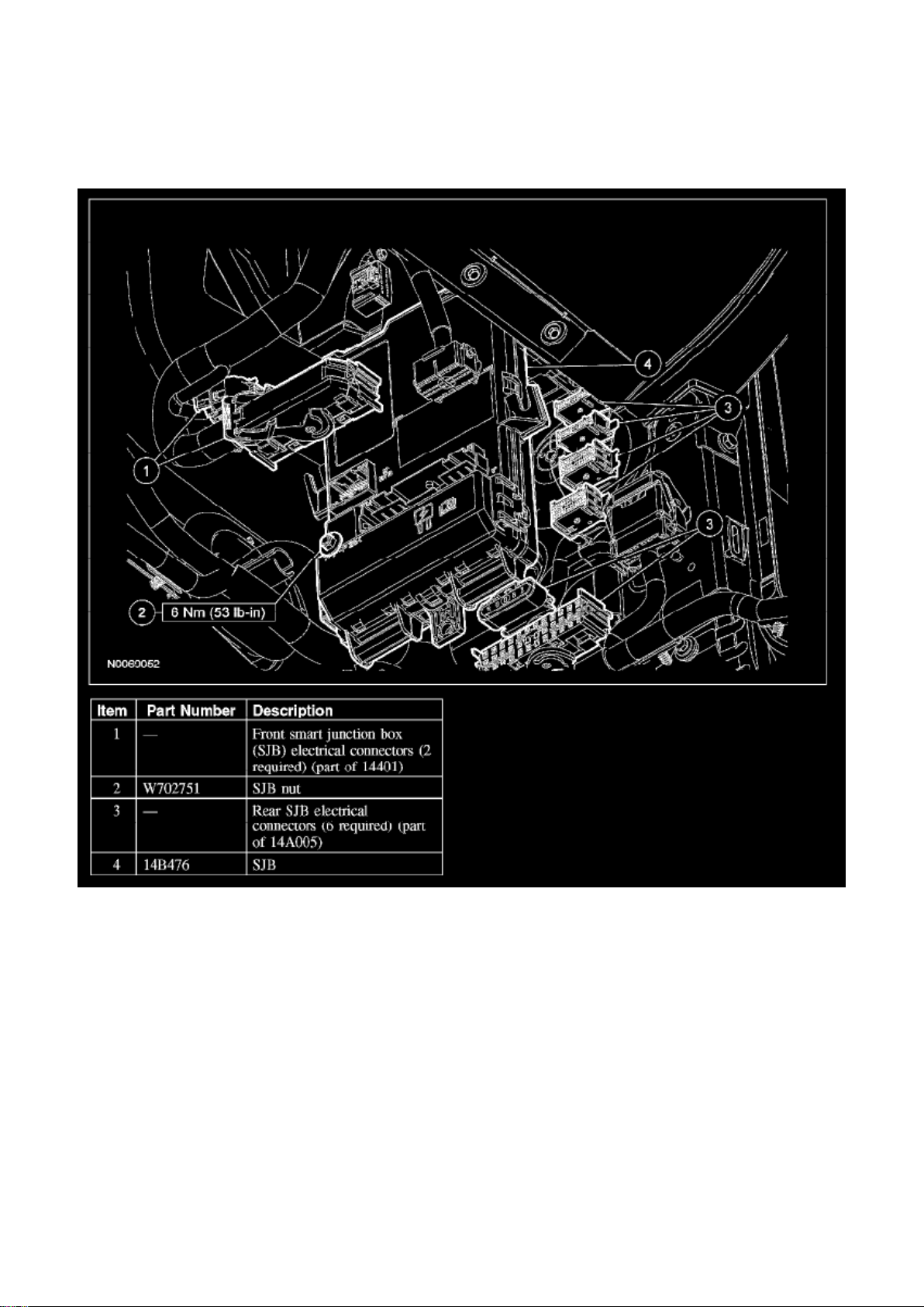
SMART JUNCTION BOX (SJB)
Removal
CAUTION: Electronic modules are sensitive to static electrical charges. If exposed to these
charges, damage may result.
NOTE:
- Prior to the removal of the module, it is necessary to upload the module configuration information
to a scan tool. This information must be downloaded into the new smart junction box (SJB) after
installation.
Page 58

- The tire pressure monitoring system (TPMS) functionality is integral to the SJB.
- A new SJB is delivered in a manufacturing mode with 6 pre-set DTCs. These DTCs require that
successful configuration of the SJB occurs, then successful TPMS sensor training occurs, then a
successful self-test occurs, including clearing of DTCs. These steps are required in order to clear
the 6 pre-set manufacturing mode DTCs. The 6 pre-set manufacturing mode DTCs are as follows: -
B2477 (Module Configuration Failure)
- B2868 (Left Front Tire Pressure Sensor Fault)
- B2869 (Right Front Tire Pressure Sensor Fault)
- B2870 (Right Rear Tire Pressure Sensor Fault)
- B2871 (Left Rear Tire Pressure Sensor Fault)
- C2780 (ECU in Manufacturer Sub-State)
1. NOTE: If the SJB is being replaced, follow this step. If the SJB is not being replaced, go to Step
2.
Upload the module configuration information from the SJB into the scan tool.
2. Remove the RH A-pillar lower trim panel.
Page 59

Ford Mustang Workshop Manual (V6-4.0L (2008))
Ford Workshop Manuals > Relays and Modules > Relays and Modules - Power and Ground Distribution > Power
Distribution Module > Component Information > Service and Repair > Page 92
Page 60

3. NOTE: The SJB electrical connector levers must click into a fully released position before they
can be removed.
Disconnect the 2 front SJB electrical connectors.
4. Remove the SJB nut. 5. Slide the SJB downward and position the SJB forward to access the
rear electrical connectors.
6. NOTE: The SJB electrical connector levers must click into a fully released position before they
can be removed.
Disconnect the 6 rear SJB electrical connectors and remove the SJB.
Installation
NOTE: When a new SJB is installed, all customer remote keyless entry (RKE) transmitters may be
required to be present in order to program the RKE transmitters to the new SJB.
1. CAUTION: Make sure the wiring harnesses are correctly routed. Pinching the wiring harnesses
between the SJB and the mounting
surface may cause damage to the wiring harness.
NOTE: Do not remove the watershield from the new SJB.
- The SJB electrical connector levers must click into a fully closed (connected) position when
installing.
Connect the 6 rear SJB electrical connectors and install the SJB.
2. Install the SJB nut.
- Tighten to 6 Nm (53 lb-in).
3. NOTE: The SJB electrical connector levers must click into a fully closed (connected) position
when installing.
Connect the 2 front SJB electrical connectors by fully engaging the levers until an audible click is
heard.
4. NOTE: If the SJB was not replaced, the procedure is completed after this step. If the SJB was
replaced, follow steps 4-7.
Install the RH A-pillar lower trim panel.
5. NOTE:
- When successful, this step provides the calibration necessary for the SJB operation and clears
the DTC B2477. The clearing of this DTC indicates the calibration data has been successfully
downloaded to the new SJB.
- When successful, this step also programs the RKE transmitters into the new SJB. In the event the
RKE transmitters do not program to the new SJB, all of the RKE transmitters will need to be
present and refer to Locks, Remote Keyless Entry Transmitter Programming. This action will
program the RKE transmitters into the new SJB. See: Accessories and Optional
Equipment/Antitheft and Alarm Systems/Keyless Entry/Keyless Entry Transmitter/Testing and
Inspection/Remote Keyless Entry Transmitter Programming
Page 61

Download the SJB configuration information from the scan tool into the new SJB.
6. NOTE: When successful, this step clears DTCs B2868, B2869, B2870, and B2871. The clearing
of these DTCs indicates the SJB has recognized
the tire pressure sensors during the tire pressure sensor training procedure.
Train the tire pressure sensors.
7. NOTE:
- This step is required to clear DTC C2780, allow the SJB to exit the manufacturing mode, and to
be sure there are no other concerns with the newly programmed SJB.
- DTC C2780 will not clear if any of the other 5 manufacturing mode DTCs are present in the SJB.
Carry out the SJB on-demand self-test. Clear the DTCs and then retrieve the DTCs to confirm all
DTCs have been cleared.
Page 62
Ford Mustang Workshop Manual (V6-4.0L (2008))
Ford Workshop Manuals > Relays and Modules > Relays and Modules - Power and Ground Distribution > Relay Box >
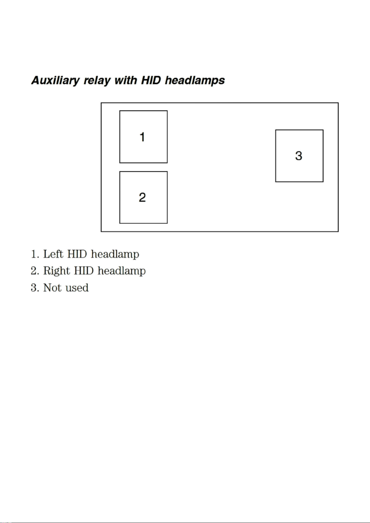
Component Information > Locations > Auxiliary Relay Box With HID Headlamps
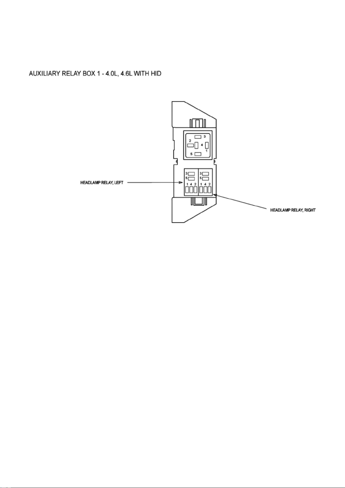
Relay Box: Locations Auxiliary Relay Box With HID Headlamps
Auxiliary Relay Box With HID Headlamps
Page 63
Ford Mustang Workshop Manual (V6-4.0L (2008))
Ford Workshop Manuals > Relays and Modules > Relays and Modules - Power and Ground Distribution > Relay Box >
Component Information > Locations > Auxiliary Relay Box With HID Headlamps > Page 97
Auxiliary Relay Box 1
Page 64
Ford Mustang Workshop Manual (V6-4.0L (2008))
Ford Workshop Manuals > Relays and Modules > Relays and Modules - Power and Ground Distribution > Relay Box >
Component Information > Locations > Auxiliary Relay Box With HID Headlamps > Page 98
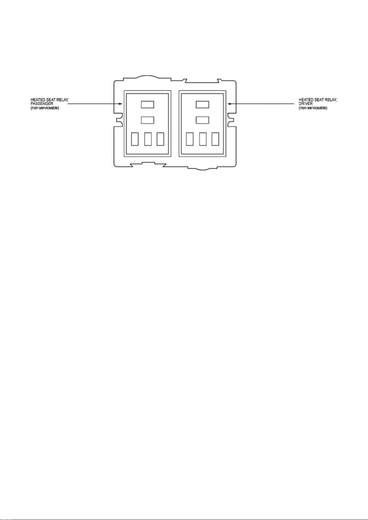
Relay Box: Locations Heated Seat Relay Box
Heated Seat Relay Box
Page 65
Ford Mustang Workshop Manual (V6-4.0L (2008))
Ford Workshop Manuals > Relays and Modules > Relays and Modules - Power and Ground Distribution > Relay Box >
Component Information > Locations > Auxiliary Relay Box With HID Headlamps > Page 99
Page 66

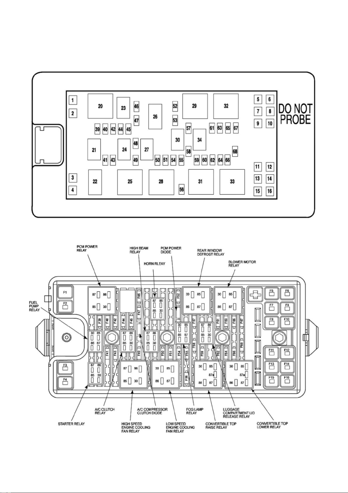
Relay Box: Locations Bussed Electrical Center (BEC) / Power Distribution Box
Bussed Electrical Center (BEC) / Power Distribution Box
Page 67
Ford Mustang Workshop Manual (V6-4.0L (2008))
Ford Workshop Manuals > Relays and Modules > Relays and Modules - Power and Ground Distribution > Relay Box >
Component Information > Locations > Auxiliary Relay Box With HID Headlamps > Page 100
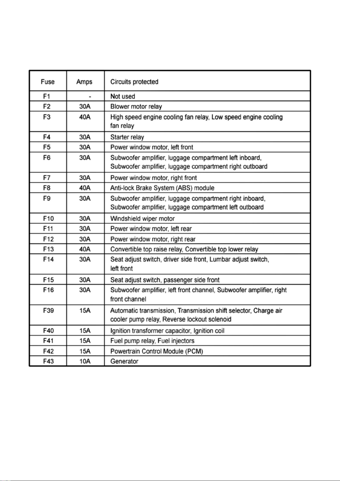
Bussed Electrical Center (BEC) / Power Distribution Box
Fuse
Page 68
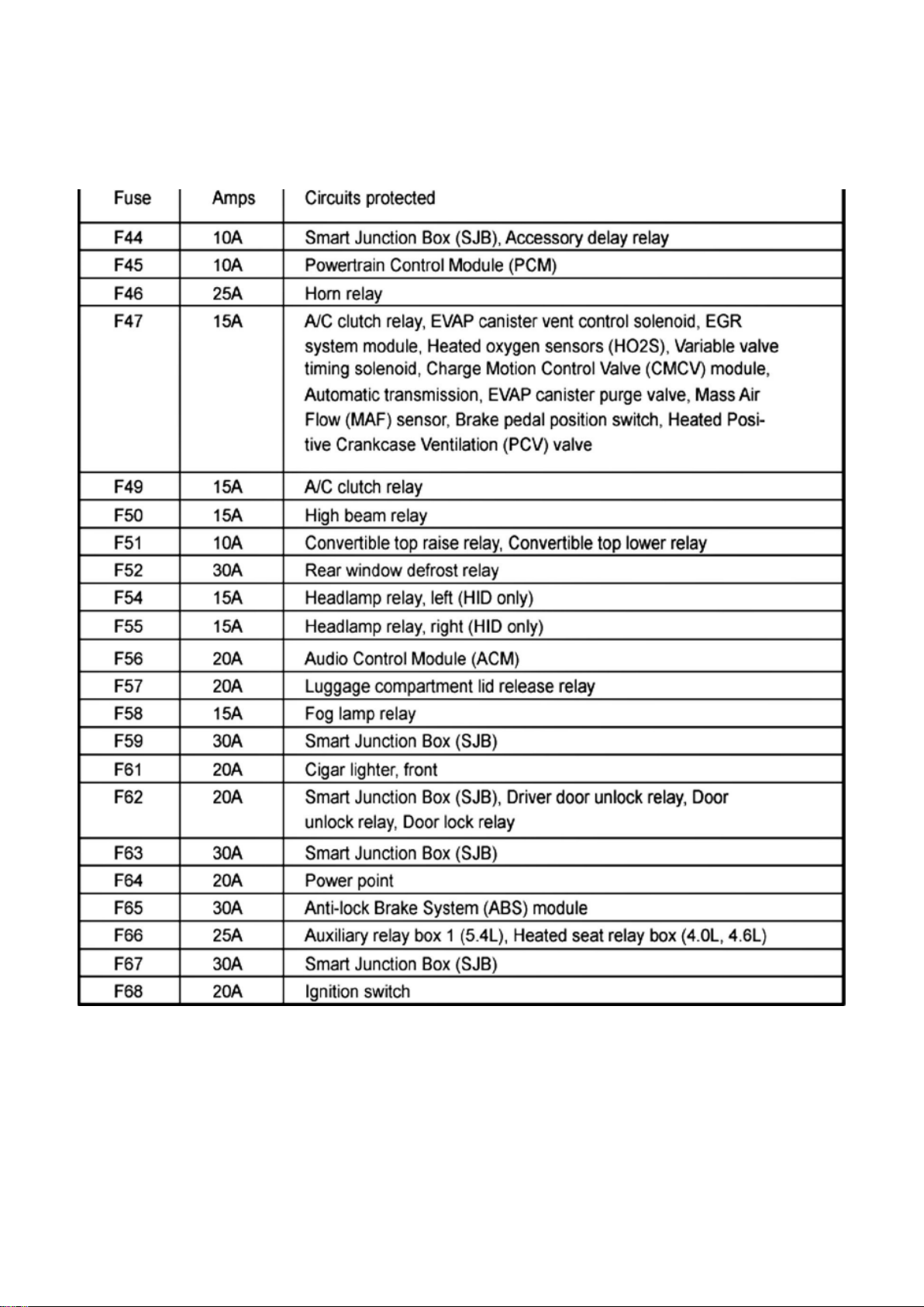
Ford Mustang Workshop Manual (V6-4.0L (2008))
Ford Workshop Manuals > Relays and Modules > Relays and Modules - Power and Ground Distribution > Relay Box >
Component Information > Locations > Auxiliary Relay Box With HID Headlamps > Page 101
Fuse
Page 69
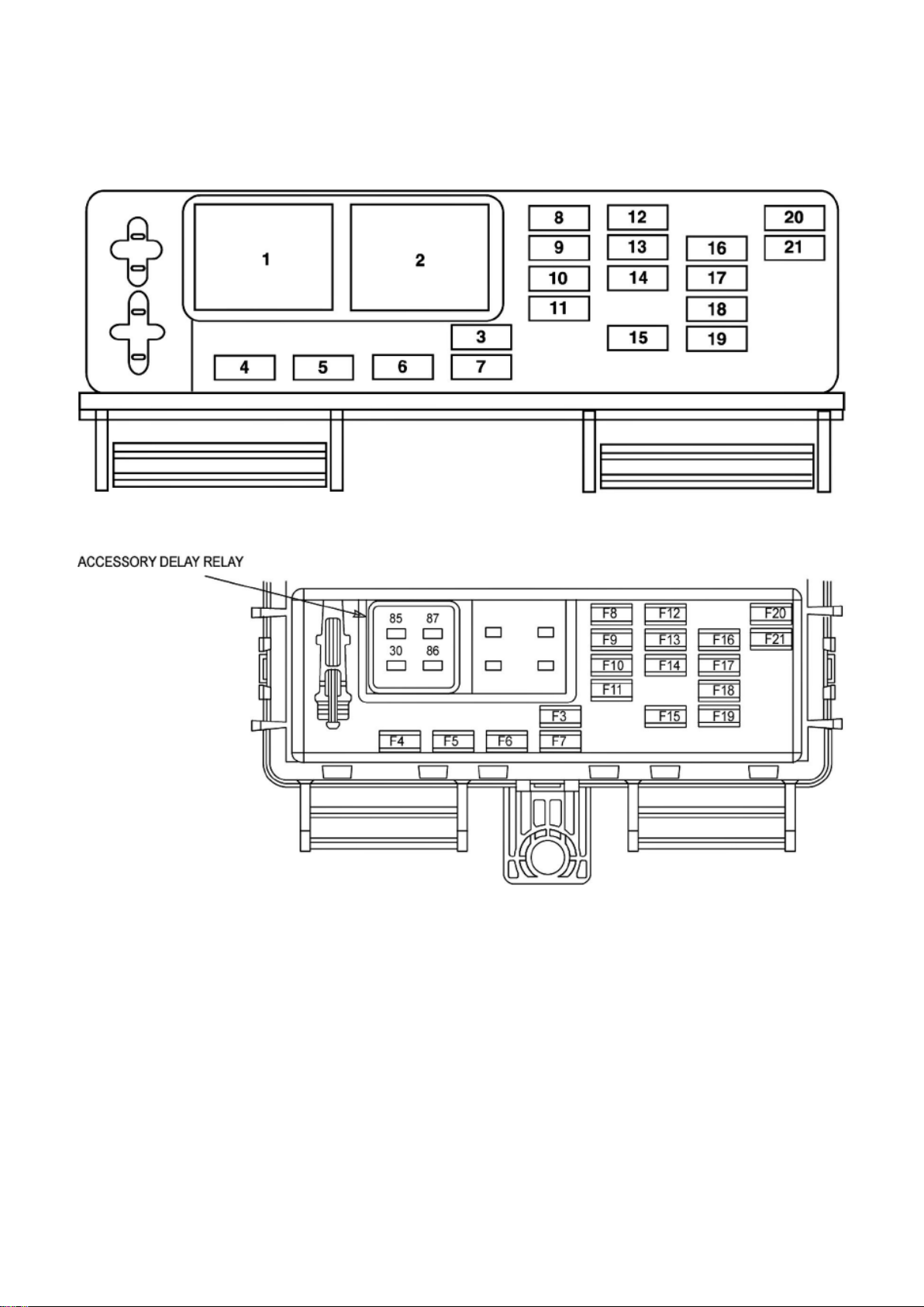
Ford Mustang Workshop Manual (V6-4.0L (2008))
Ford Workshop Manuals > Relays and Modules > Relays and Modules - Power and Ground Distribution > Relay Box >
Component Information > Locations > Auxiliary Relay Box With HID Headlamps > Page 102
Relay Box: Locations Smart Junction Box (SJB) / Passenger Compartment Fuse Panel
Smart Junction Box (SJB) / Passenger Compartment Fuse Panel
Smart Junction Box (SJB) / Passenger Compartment Fuse Panel
Page 70
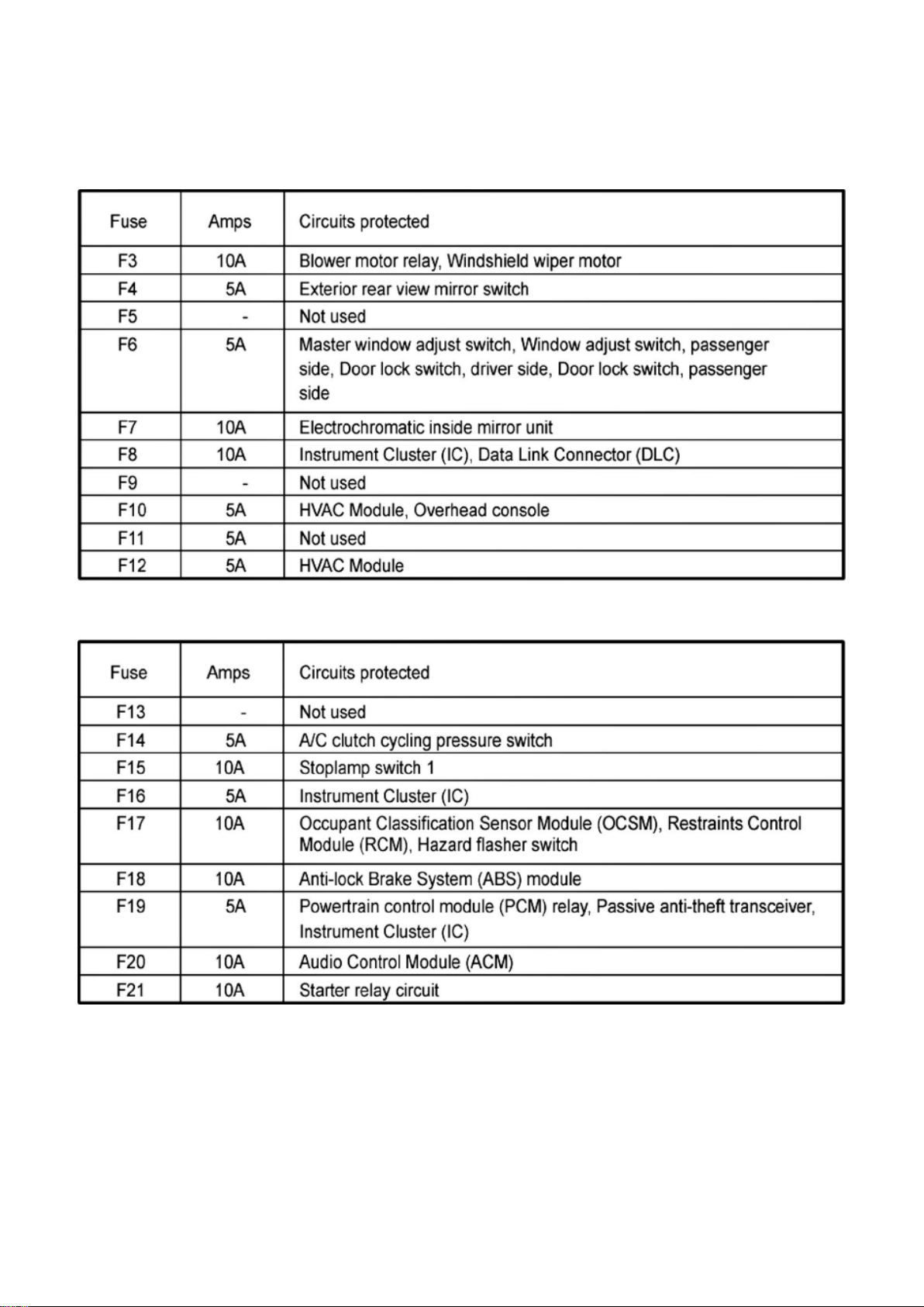
Ford Mustang Workshop Manual (V6-4.0L (2008))
Ford Workshop Manuals > Relays and Modules > Relays and Modules - Power and Ground Distribution > Relay Box >
Component Information > Locations > Auxiliary Relay Box With HID Headlamps > Page 103
Fuse
Fuse
Page 71
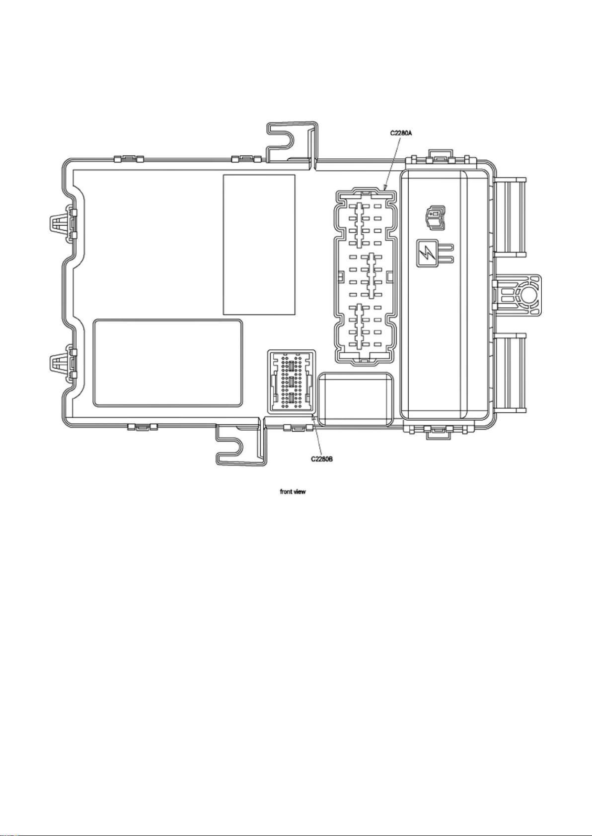
Ford Mustang Workshop Manual (V6-4.0L (2008))
Ford Workshop Manuals > Relays and Modules > Relays and Modules - Power and Ground Distribution > Relay Box >
Component Information > Locations > Auxiliary Relay Box With HID Headlamps > Page 104
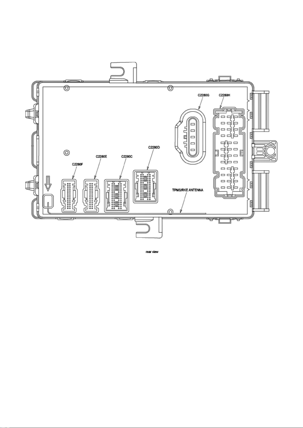
Smart Junction Box (SJB) / Passenger Compartment Fuse Panel - Front View
Page 72
Ford Mustang Workshop Manual (V6-4.0L (2008))
Ford Workshop Manuals > Relays and Modules > Relays and Modules - Power and Ground Distribution > Relay Box >
Component Information > Locations > Auxiliary Relay Box With HID Headlamps > Page 105
Smart Junction Box (SJB) / Passenger Compartment Fuse Panel - Rear View
Page 73
Ford Mustang Workshop Manual (V6-4.0L (2008))
Ford Workshop Manuals > Relays and Modules > Relays and Modules - Power and Ground Distribution > Relay Box >
Component Information > Diagrams > Bussed Electrical Center (BEC)
Page 74

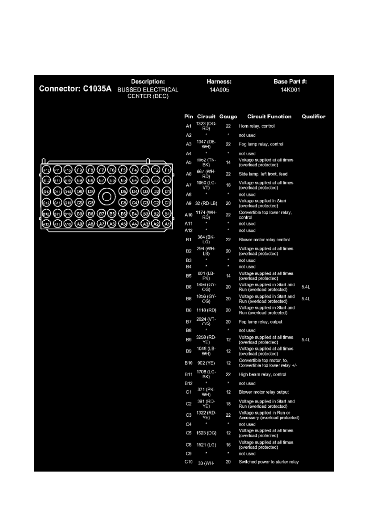
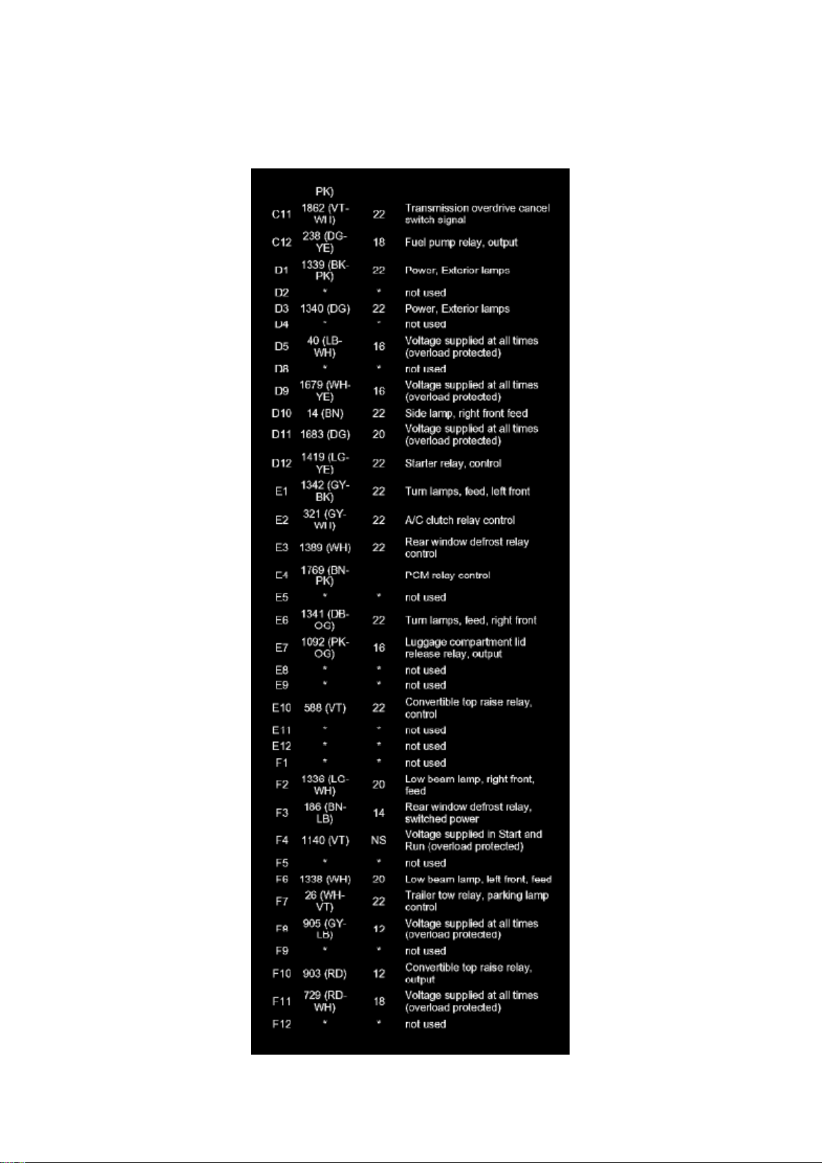
Relay Box: Diagrams Bussed Electrical Center (BEC)
C1035A (Part 1)
Page 75
Ford Mustang Workshop Manual (V6-4.0L (2008))
Ford Workshop Manuals > Relays and Modules > Relays and Modules - Power and Ground Distribution > Relay Box >
Component Information > Diagrams > Bussed Electrical Center (BEC) > Page 108
Page 76

C1035A (Part 2)
Page 77
Ford Mustang Workshop Manual (V6-4.0L (2008))
Ford Workshop Manuals > Relays and Modules > Relays and Modules - Power and Ground Distribution > Relay Box >
Component Information > Diagrams > Bussed Electrical Center (BEC) > Page 109
Page 78

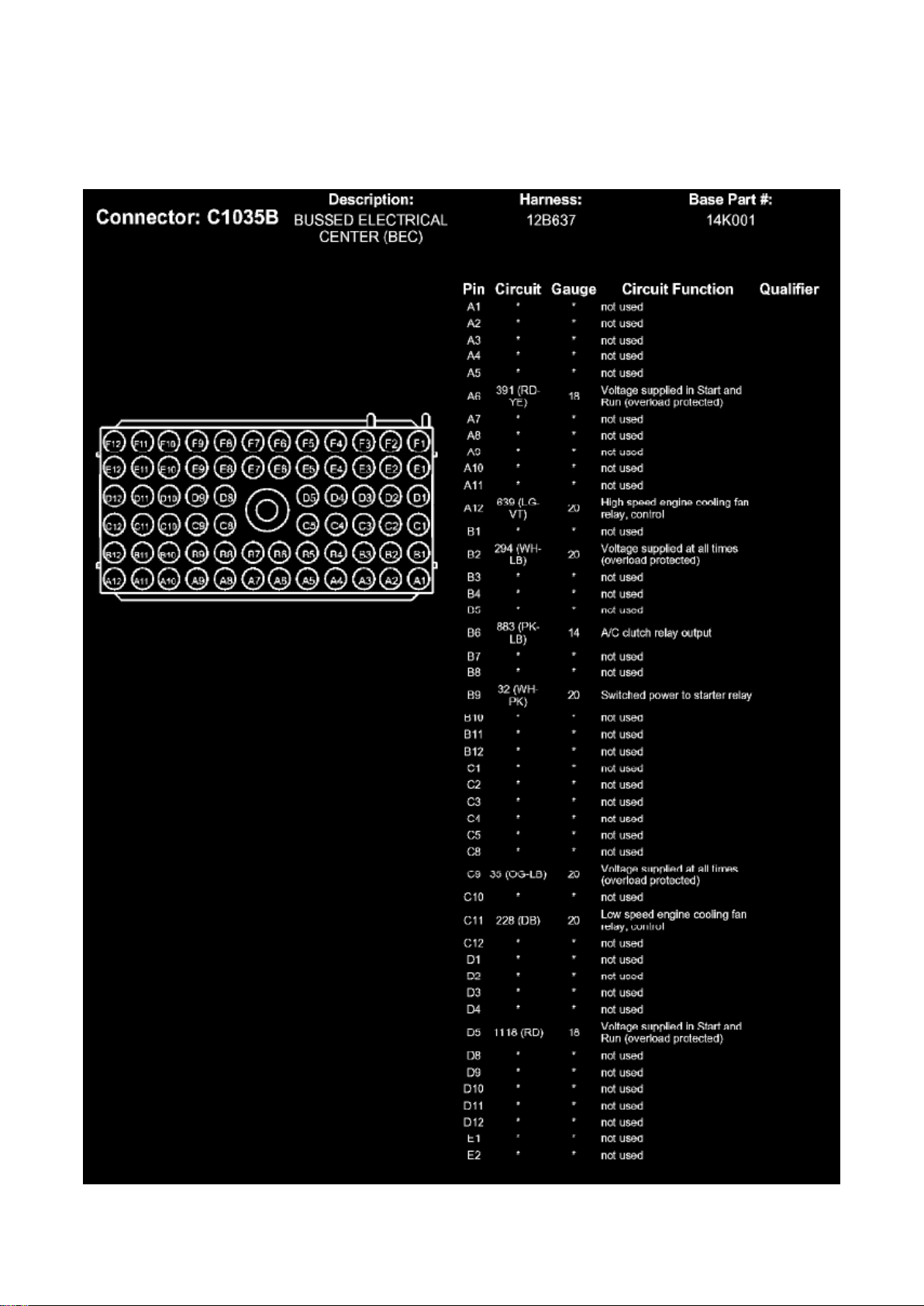
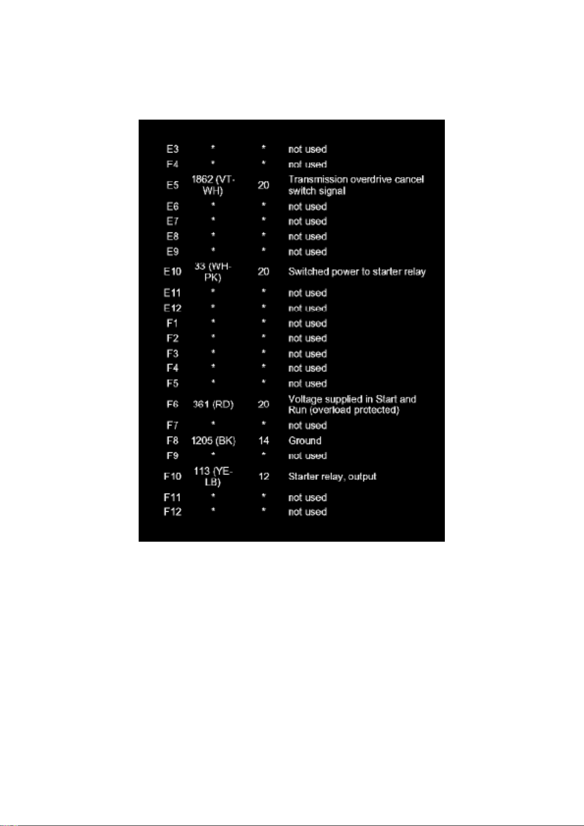
C1035B (Part 1)
Page 79
Ford Mustang Workshop Manual (V6-4.0L (2008))
Ford Workshop Manuals > Relays and Modules > Relays and Modules - Power and Ground Distribution > Relay Box >
Component Information > Diagrams > Bussed Electrical Center (BEC) > Page 110
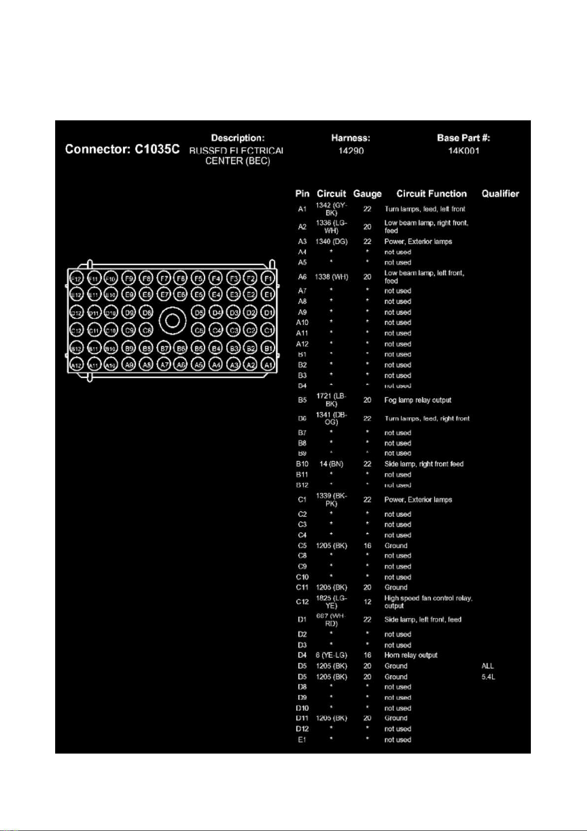
C1035B (Part 2)
Page 80
Ford Mustang Workshop Manual (V6-4.0L (2008))
Ford Workshop Manuals > Relays and Modules > Relays and Modules - Power and Ground Distribution > Relay Box >
Component Information > Diagrams > Bussed Electrical Center (BEC) > Page 111
Page 81

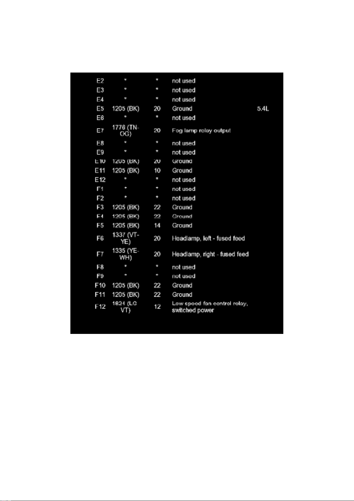
C1035C (Part 1)
Page 82
Ford Mustang Workshop Manual (V6-4.0L (2008))
Ford Workshop Manuals > Relays and Modules > Relays and Modules - Power and Ground Distribution > Relay Box >
Component Information > Diagrams > Bussed Electrical Center (BEC) > Page 112
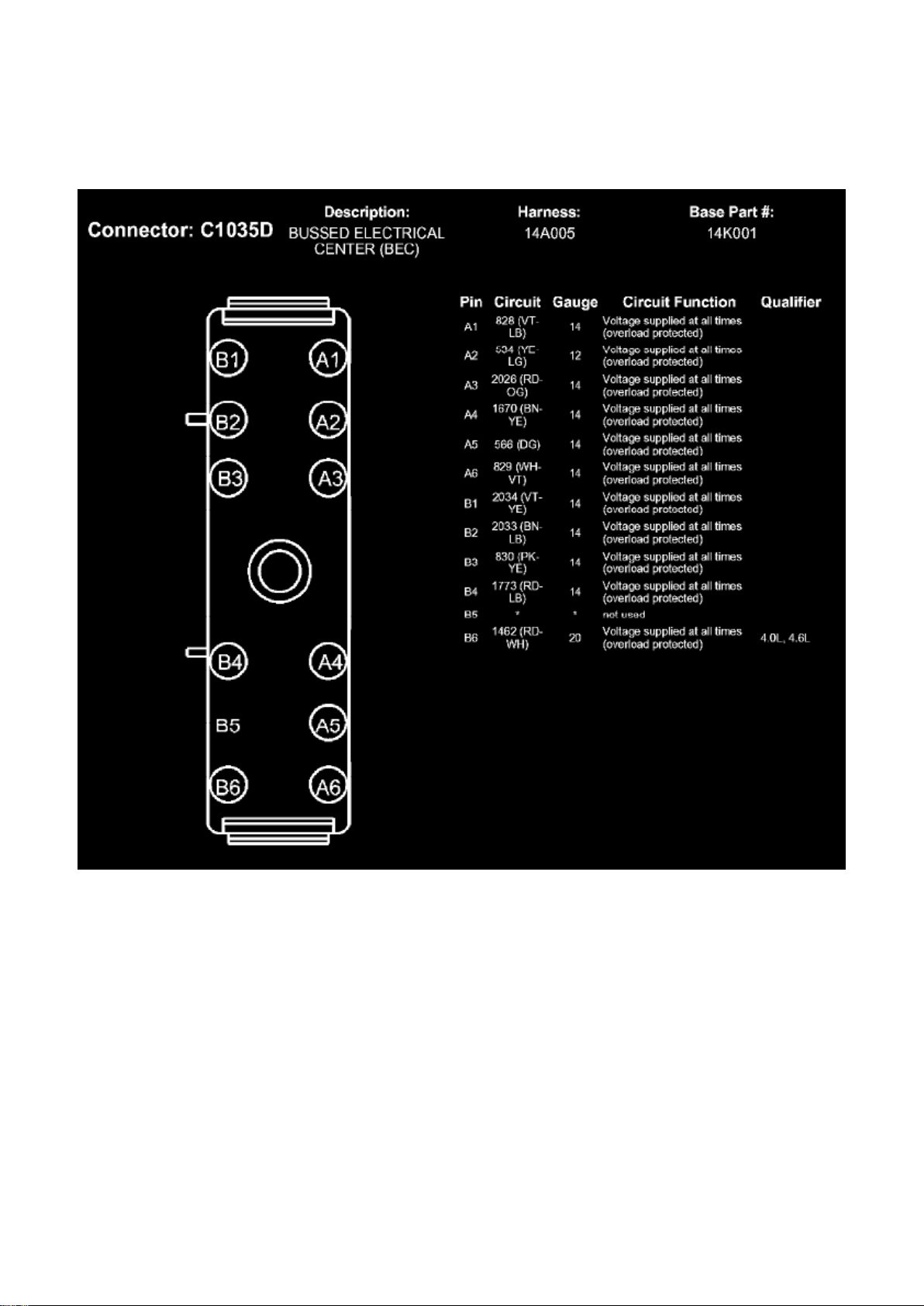
C1035C (Part 2)
Page 83
Ford Mustang Workshop Manual (V6-4.0L (2008))
Ford Workshop Manuals > Relays and Modules > Relays and Modules - Power and Ground Distribution > Relay Box >
Component Information > Diagrams > Bussed Electrical Center (BEC) > Page 113
C1035D
Page 84
Ford Mustang Workshop Manual (V6-4.0L (2008))
Ford Workshop Manuals > Relays and Modules > Relays and Modules - Power and Ground Distribution > Relay Box >
Component Information > Diagrams > Bussed Electrical Center (BEC) > Page 114
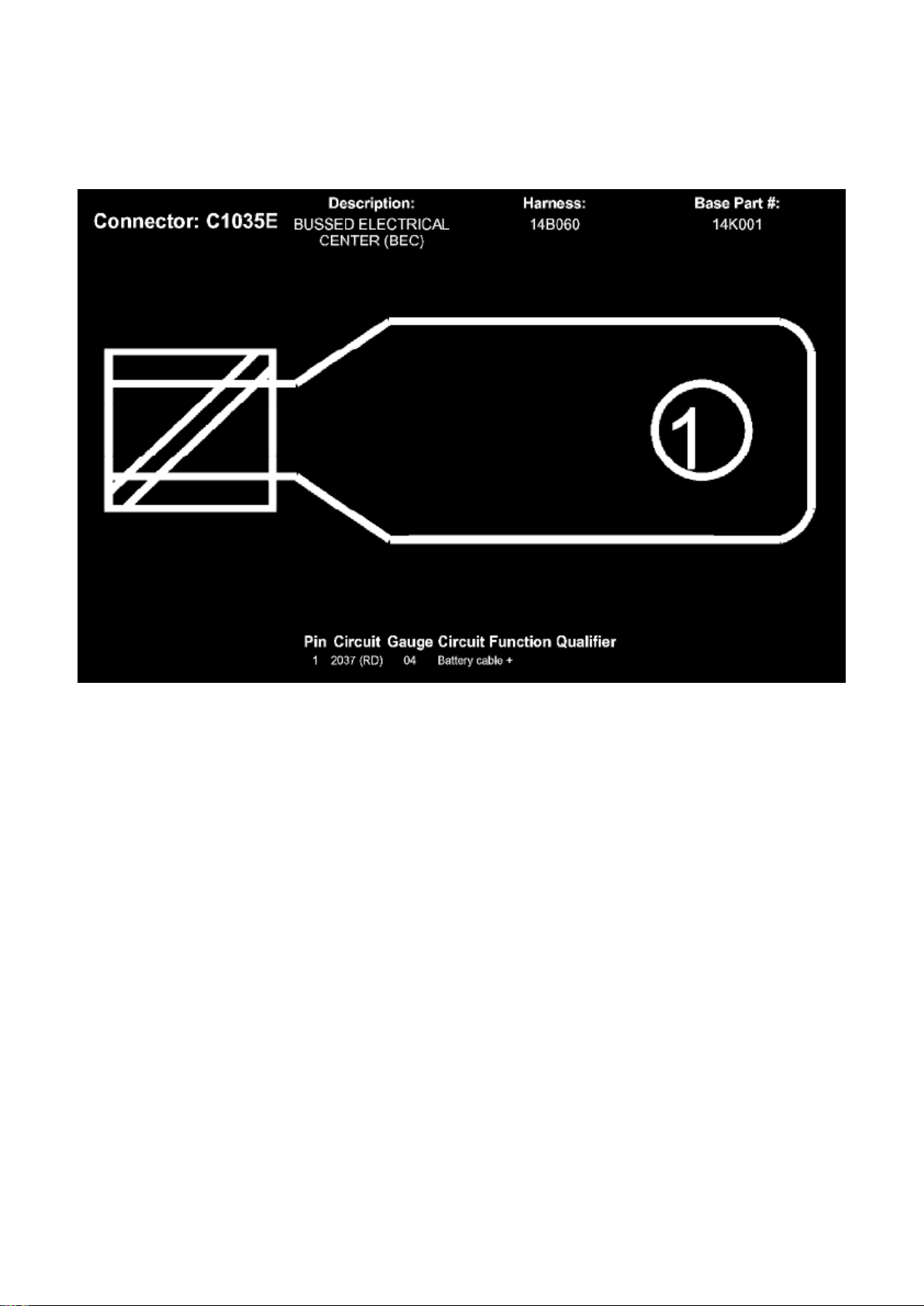
C1035E
Page 85
Ford Mustang Workshop Manual (V6-4.0L (2008))
Ford Workshop Manuals > Relays and Modules > Relays and Modules - Power and Ground Distribution > Relay Box >
Component Information > Diagrams > Bussed Electrical Center (BEC) > Page 115
Page 86

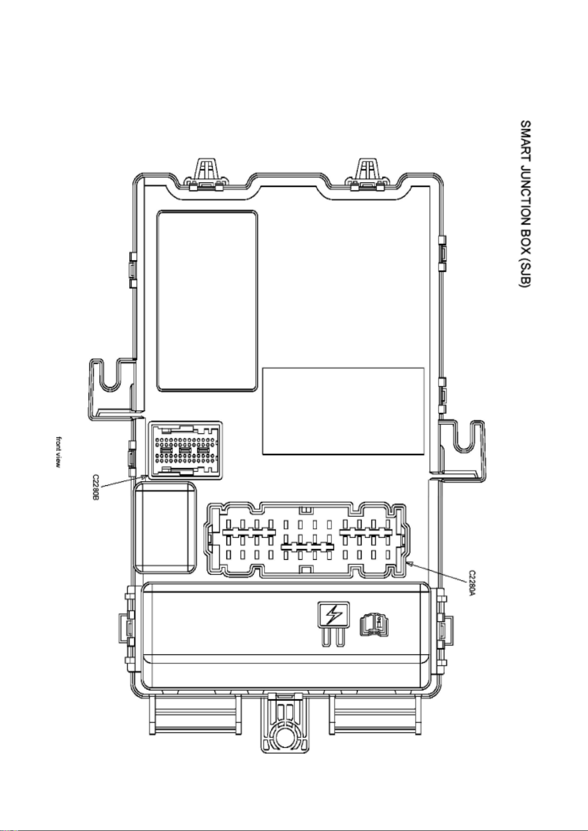
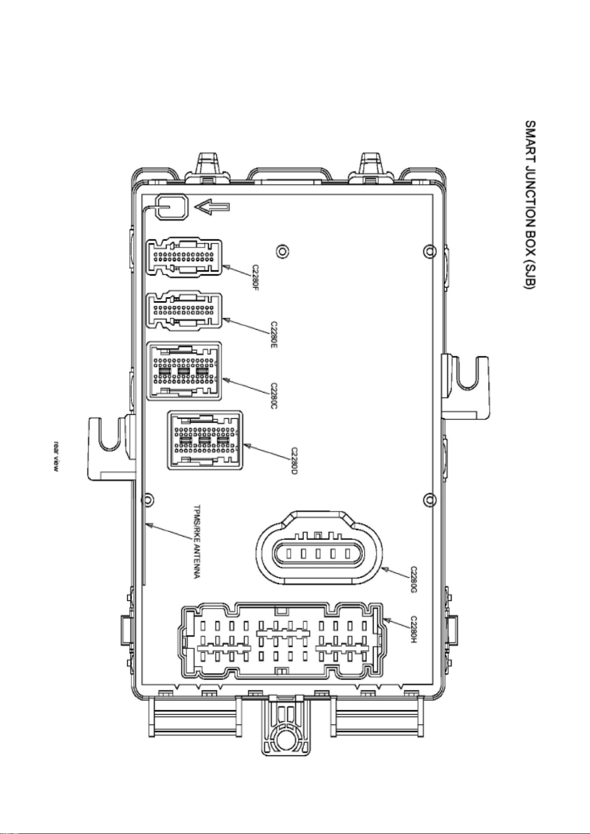
Relay Box: Diagrams Smart Junction Box (SJB)
Page 87
Ford Mustang Workshop Manual (V6-4.0L (2008))
Ford Workshop Manuals > Relays and Modules > Relays and Modules - Power and Ground Distribution > Relay Box >
Component Information > Diagrams > Bussed Electrical Center (BEC) > Page 116
Page 88

Page 89
Ford Mustang Workshop Manual (V6-4.0L (2008))
Ford Workshop Manuals > Relays and Modules > Relays and Modules - Power and Ground Distribution > Relay Box >
Component Information > Diagrams > Bussed Electrical Center (BEC) > Page 117
Page 90

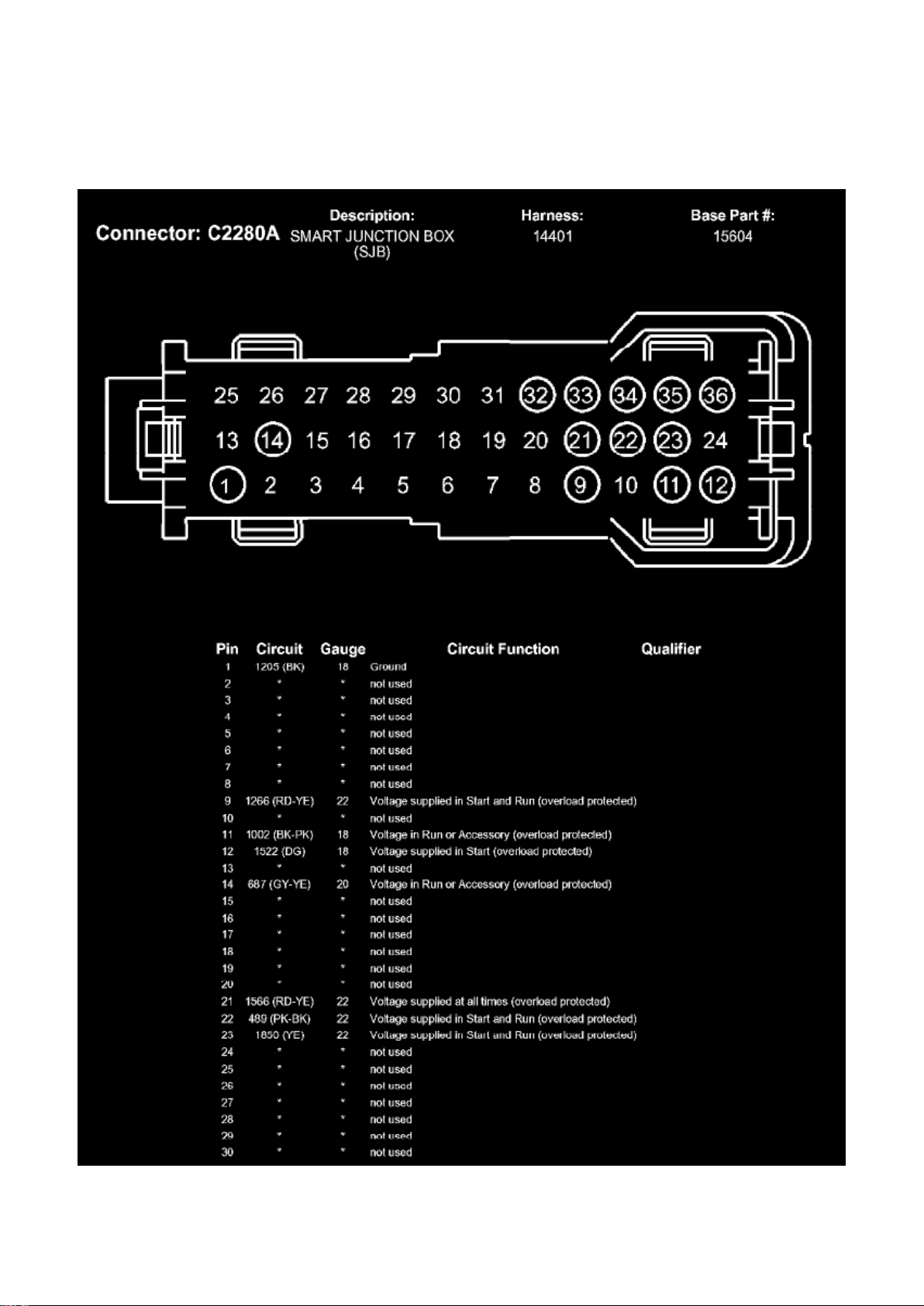
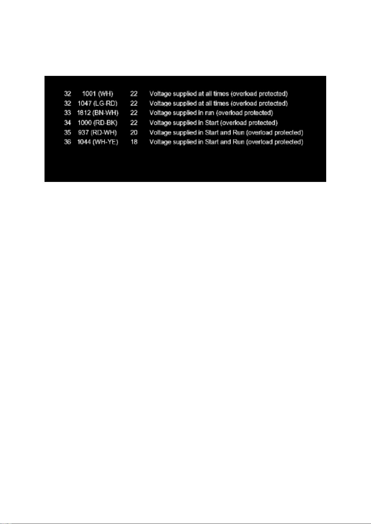
C2280A (Part 1)
Page 91
Ford Mustang Workshop Manual (V6-4.0L (2008))
Ford Workshop Manuals > Relays and Modules > Relays and Modules - Power and Ground Distribution > Relay Box >
Component Information > Diagrams > Bussed Electrical Center (BEC) > Page 118
C2280A (Part 2)
Page 92
Ford Mustang Workshop Manual (V6-4.0L (2008))
Ford Workshop Manuals > Relays and Modules > Relays and Modules - Power and Ground Distribution > Relay Box >
Component Information > Diagrams > Bussed Electrical Center (BEC) > Page 119
Page 93

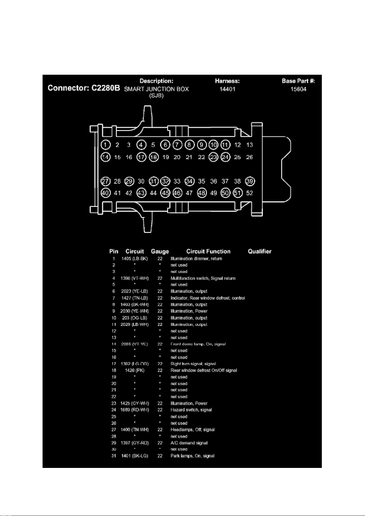
C2280B (Part 1)
Page 94
Ford Mustang Workshop Manual (V6-4.0L (2008))
Ford Workshop Manuals > Relays and Modules > Relays and Modules - Power and Ground Distribution > Relay Box >
Component Information > Diagrams > Bussed Electrical Center (BEC) > Page 120
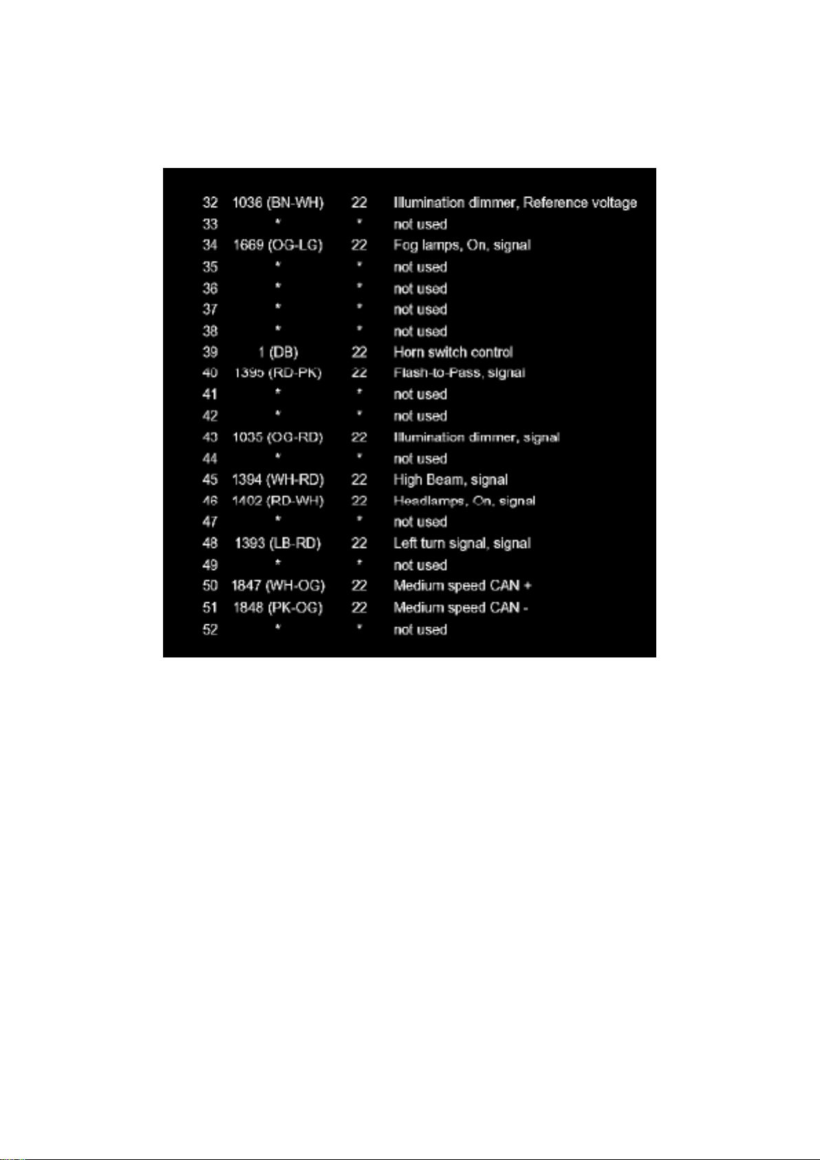
C2280B (Part 2)
Page 95
Ford Mustang Workshop Manual (V6-4.0L (2008))
Ford Workshop Manuals > Relays and Modules > Relays and Modules - Power and Ground Distribution > Relay Box >
Component Information > Diagrams > Bussed Electrical Center (BEC) > Page 121
Page 96

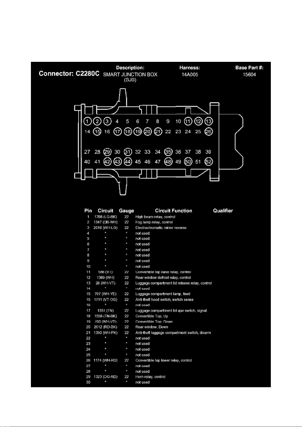
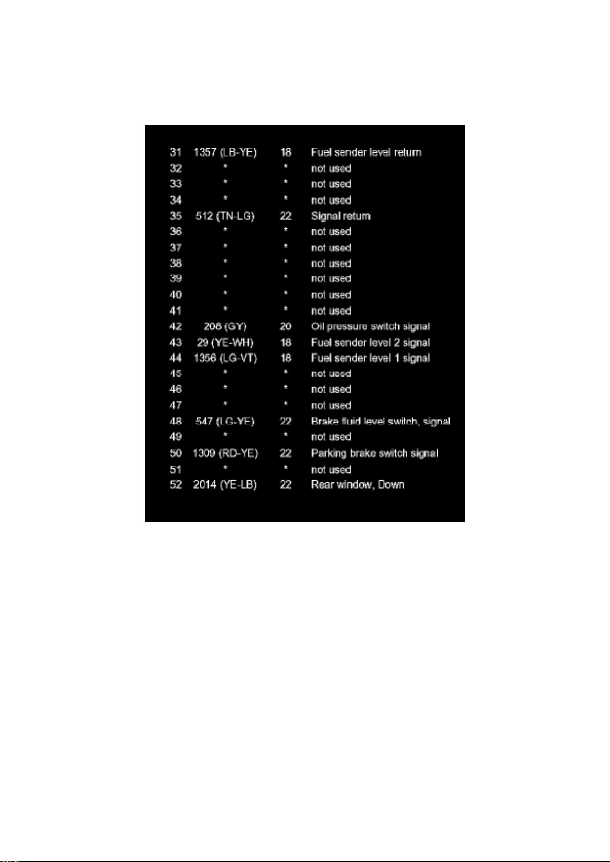
C2280C (Part 1)
Page 97
Ford Mustang Workshop Manual (V6-4.0L (2008))
Ford Workshop Manuals > Relays and Modules > Relays and Modules - Power and Ground Distribution > Relay Box >
Component Information > Diagrams > Bussed Electrical Center (BEC) > Page 122
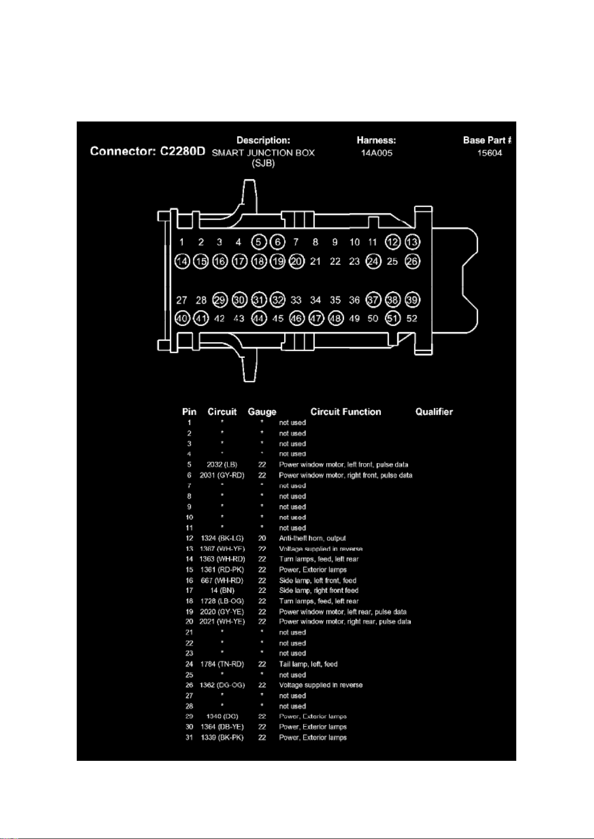
C2280C (Part 2)
Page 98
Ford Mustang Workshop Manual (V6-4.0L (2008))
Ford Workshop Manuals > Relays and Modules > Relays and Modules - Power and Ground Distribution > Relay Box >
Component Information > Diagrams > Bussed Electrical Center (BEC) > Page 123
Page 99

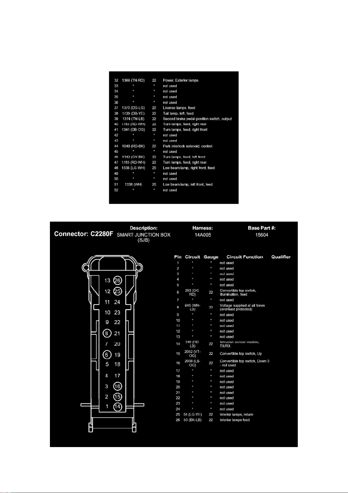
C2280D (Part 1)
Page 100
Ford Mustang Workshop Manual (V6-4.0L (2008))
Ford Workshop Manuals > Relays and Modules > Relays and Modules - Power and Ground Distribution > Relay Box >
Component Information > Diagrams > Bussed Electrical Center (BEC) > Page 124
 Loading...