

Page 1

FORD FUSION Owner's Manual
Page 2

The information contained in this publication was correct at the time of going to print. In the interest of
development the right is reserved to change specifications, design or equipment at any time without
notice and without incurring any obligations. This publication, or part thereof, may not be reproduced nor
translated without our approval. Errors and omissions excepted.
© Ford Motor Company 2011
All rights reserved.
Part Number: (CG3441en) 03/2011 20110408104927
Page 3

Introduction
About This Manual...........................................5
Symbols Glossary.............................................5
Parts and Accessories.....................................5
At a Glance
At a Glance..........................................................8
Child Safety
Child Seats.........................................................15
Booster Seats...................................................16
Child Seat Positioning....................................17
Child Safety Locks..........................................19
Occupant protection
Principle of Operation..................................20
Fastening the seat belts...............................22
Seat belt height adjustment......................22
Using seat belts during pregnancy..........23
Disabling the passenger airbag.................23
Keys and Remote Controls
General Information on Radio
Frequencies..................................................25
Programming the remote control............25
Changing the remote control
battery............................................................26
Locks
Locking and Unlocking.................................27
Engine immobiliser
Principle of Operation..................................29
Coded keys.......................................................29
Arming the engine immobiliser................29
Disarming the engine immobiliser...........29
Alarm
Arming the alarm...........................................30
Disarming the alarm.....................................30
Steering Wheel
Adjusting the Steering Wheel.....................31
Audio Control....................................................31
Wipers and Washers
Windscreen Wipers.......................................33
Windscreen Washers....................................34
Rear Window Wiper and Washers...........34
Checking the Wiper Blades........................35
Changing the Wiper Blades........................35
Lighting
Lighting Control...............................................37
Front Fog Lamps............................................38
Rear Fog Lamps..............................................38
Headlamp Levelling......................................39
Hazard Warning Flashers............................39
Direction Indicators.......................................40
Interior Lamps.................................................40
Removing a Headlamp.................................41
Changing a Bulb.............................................42
Bulb Specification Chart.............................46
Windows and Mirrors
Power Windows..............................................47
Exterior Mirrors................................................47
Electric exterior mirrors................................47
Instrument Cluster
Gauges...............................................................49
Warning Lamps and Indicators................50
Information Displays
General Information......................................53
Personalised Settings..................................54
Information Messages..................................55
Climate Control
Principle of Operation..................................58
1
Table of Contents
Page 4

Air Vents............................................................58
Manual Climate Control..............................58
Automatic Climate Control.......................60
Heated Windows and Mirrors....................62
Auxiliary Heater...............................................62
Sunroof..............................................................62
Seats
Sitting in the Correct Position...................64
Manual Seats..................................................64
Rear Seats........................................................65
Head Restraints..............................................66
Heated Seats...................................................67
Front Seat Armrest.......................................68
Convenience features
Cigar Lighter.....................................................69
Glove Box..........................................................69
Storage compartments...............................69
Rear Seat Armrest...........................................71
Floor Mats...........................................................71
Starting and Stopping the
Engine
General Information......................................72
Ignition Switch.................................................72
Starting a Petrol Engine...............................72
Starting a Diesel Engine...............................73
Switching Off the Engine.............................74
Fuel and Refuelling
Safety Precautions.........................................75
Fuel Quality - Petrol......................................75
Fuel Quality - Diesel......................................75
Catalytic Converter........................................75
Fuel filler flap...................................................76
Refuelling..........................................................76
Fuel Consumption.........................................76
Technical Specifications..............................76
Transmission
Manual Transmission...................................78
Automatic Transmission - Vehicles With:
4-Speed Automatic Transmission
(4F27E)..........................................................79
Brakes
Principle of Operation..................................82
Hints on Driving With Anti-Lock
Brakes.............................................................82
Parking Brake...................................................82
Stability Control
Principle of Operation..................................83
Using Stability Control.................................83
Parking Aids
Principle of Operation..................................84
Using the Parking Aid...................................84
Load Carrying
General Information.....................................86
Luggage Covers..............................................86
Roof Racks and Load Carriers..................86
Towing
Towing a Trailer..............................................88
Tow Ball.............................................................88
Driving Hints
General Driving Points..................................92
Running-In........................................................92
Cold Weather Precautions..........................92
Driving Through Water.................................92
Roadside Emergencies
First Aid Kit.......................................................93
Warning Triangle............................................93
2
Table of Contents
Page 5

Status after a collision
Fuel Cut-Off Switch......................................94
Fuses
Changing a Fuse.............................................96
Fuse Labels......................................................96
Fuse Box Locations.......................................98
Vehicle recovery
Towing Points..................................................99
Towing the Vehicle on Four Wheels.......99
Maintenance
General Information...................................100
Opening and Closing the Bonnet............101
Under Bonnet Overview - 1.25L
Duratec-16V (Sigma)/1.4L
Duratec-16V (Sigma)/1.6L
Duratec-16V (Sigma).............................102
Under Bonnet Overview - 1.4L
Duratorq-TDCi (DV) Diesel..................104
Under Bonnet Overview - 1.6L
Duratorq-TDCi (DV) Diesel..................105
Engine Oil Dipstick - 1.25L Duratec-16V
(Sigma)/1.4L Duratec-16V
(Sigma)/1.6L Duratec-16V
(Sigma).......................................................106
Engine Oil Dipstick - 1.4L Duratorq-TDCi
(DV) Diesel.................................................106
Engine Oil Dipstick - 1.6L Duratorq-TDCi
(DV) Diesel.................................................107
Engine Oil Check...........................................107
Engine Coolant Check................................107
Power Steering Fluid Check.....................108
Brake and Clutch Fluid Check.................108
Washer Fluid Check....................................109
Technical Specifications...........................109
Vehicle care
Cleaning the Exterior....................................112
Cleaning the Interior.....................................112
Repairing Minor Paint Damage.................113
Vehicle battery
Jump-Starting the Vehicle.........................114
Wheels and Tyres
General Information.....................................116
Changing a Road Wheel.............................116
Tyre Repair Kit.................................................121
Tyre Care..........................................................124
Using Winter Tyres.......................................124
Using Snow Chains......................................124
Technical Specifications............................125
Vehicle identification
Vehicle Identification Plate.......................126
Vehicle Identification Number.................126
Engine number..............................................126
Capacities and Specific-
ations
Dimensions......................................................127
Audio introduction
Important audio information....................131
Audio unit overview
Audio unit overview......................................132
Audio system security
Security code.................................................136
Lost security code........................................136
Entering a security code.............................136
Incorrect security code...............................136
Audio unit clock and date
displays
Setting the clock and date on the audio
unit..................................................................137
Audio unit operation
On/off control................................................138
3
Table of Contents
Page 6

Bass/treble control......................................138
Balance/fade control..................................138
Audio menu control.....................................138
Station preset buttons................................141
Waveband button.........................................141
Autostore control..........................................141
Traffic information control.........................141
Station tuning control.................................143
Audio unit menus
Automatic volume control........................145
Digital signal processing (DSP)..............145
Audio distortion reduction (CLIP)..........145
Alternative frequencies..............................146
Regional mode (REG)................................146
News broadcasts..........................................147
Compact disc player
Loading compact discs..............................148
Track selection..............................................148
Compact disc playback.............................149
Compact disc selection.............................149
Fast forward/reverse...................................149
Shuffle/random............................................149
Compact disc track compression..........150
Compact disc track scanning..................150
Ejecting compact discs..............................150
Repeat compact disc tracks......................151
Ending compact disc playback................151
Ejecting multiple compact discs .............151
Auxiliary input (AUX IN)
socket
Auxiliary input (AUX IN) socket...............152
Audio troubleshooting
Audio troubleshooting................................153
Telephone
General Information....................................155
Telephone setup...........................................155
Bluetooth setup............................................156
Telephone controls......................................157
Using the telephone - Vehicles Without:
Navigation System..................................158
Using the telephone - Vehicles With:
Travel Pilot EX.............................................161
Voice control
Principle of Operation.................................163
Using voice control......................................163
Audio unit commands................................164
Telephone commands...............................168
Navigation system commands................173
Climate control commands......................173
Appendices
Electromagnetic compatibility................176
Type approvals...............................................177
4
Table of Contents
Page 7

ABOUT THIS MANUAL
Thank you for choosing Ford. We
recommend that you take some time to
get to know your vehicle by reading this
manual. The more that you know about it,
the greater the safety and pleasure you
will get from driving it.
WARNING
Always drive with due care and
attention when using and operating
the controls and features on your
vehicle.
Note: This manual describes product
features and options available throughout
the range, sometimes even before they are
generally available. It may describe options
not fitted to your vehicle.
Note: Some of the illustrations in this
manual may be used for different models,
so may appear different to your vehicle.
However, the essential information in the
illustrations is always correct.
Note: Always use and operate your vehicle
in line with all applicable laws and
regulations.
Note: Pass on this manual when selling
your vehicle. It is an integral part of the
vehicle.
This vehicle has received the endorsement
of TÜV, the accredited international testing
organisation, for its allergy-friendly
properties.
All materials used in the manufacture of
the interior of this vehicle meet strict
requirements of the TÜV TOXPROOF
Criteria Catalogue for Vehicle Interiors by
TÜV Produkt and Umwelt GmbH and are
designed to minimize the risk of allergic
reactions.
Additionally an efficient pollen filter
protects the passengers against allergen
particles in the outdoor air.
For more information, contact TÜV at
www.tuv.com.
SYMBOLS GLOSSARY
Symbols in this handbook
WARNING
You risk death or serious injury to
yourself and others if you do not
follow the instructions highlighted
by the warning symbol.
CAUTION
You risk damaging your vehicle if you
do not follow the instructions
highlighted by the caution symbol.
Symbols on your vehicle
When you see these symbols, read and
follow the relevant instructions in this
handbook before touching or attempting
adjustment of any kind.
PARTS AND ACCESSORIES
Now you can be sure that your Ford
parts are Ford parts
Your Ford has been built to the highest
standards using high quality Ford Original
Parts. As a result, you can enjoy driving it
for many years.
5
Introduction
Page 8
Should the unexpected occur and a major
part needs replacing, we recommend that
you accept nothing less than Ford Original
Parts.
The use of Ford Original Parts ensures that
your vehicle is repaired to its pre-accident
condition and maintains its maximum
residual value.
Ford Original Parts match Ford's stringent
safety requirements and high standards
of fit, finish and reliability. Quite simply,
they represent the best overall repair value,
including parts and labour costs.
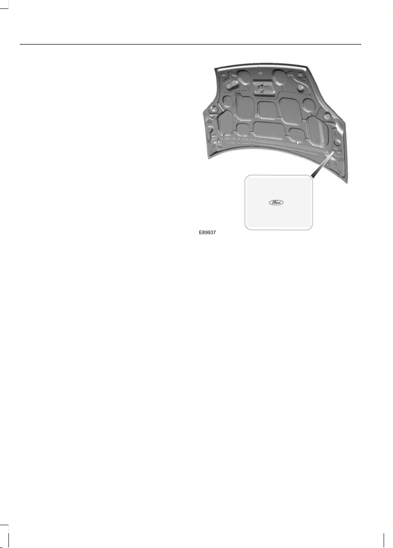
Now it is easier to tell if you have really
been given Ford Original Parts. The Ford
logo is clearly visible on the following parts
if they are Ford Original Parts. If your
vehicle has to be repaired, look for the
clearly visible Ford branding and make sure
that only Ford Original Parts have been
used.
Look for the Ford logo on the
following parts
Sheet metal
• Bonnet
• Wings
• Doors
• Tailgate
E89937
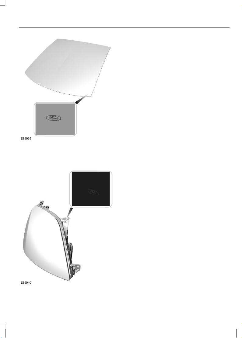
Bumper and radiator grille
• Radiator grille
• Front and rear bumper
Glass
• Rear window
• Side glass
• Windscreen
6
Introduction
Page 9
E89939
Lighting
• Rear lamps
• Headlamp
E89940
7
Introduction
Page 10
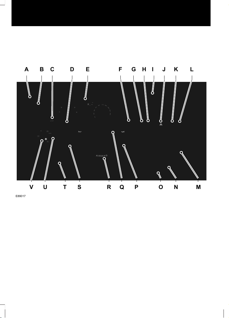
AT A GLANCE
Instrument panel overview
Left-hand drive
A
V T R MNOPQSU
B D F G HE KJI LC
E89017
8
At a Glance
Page 11
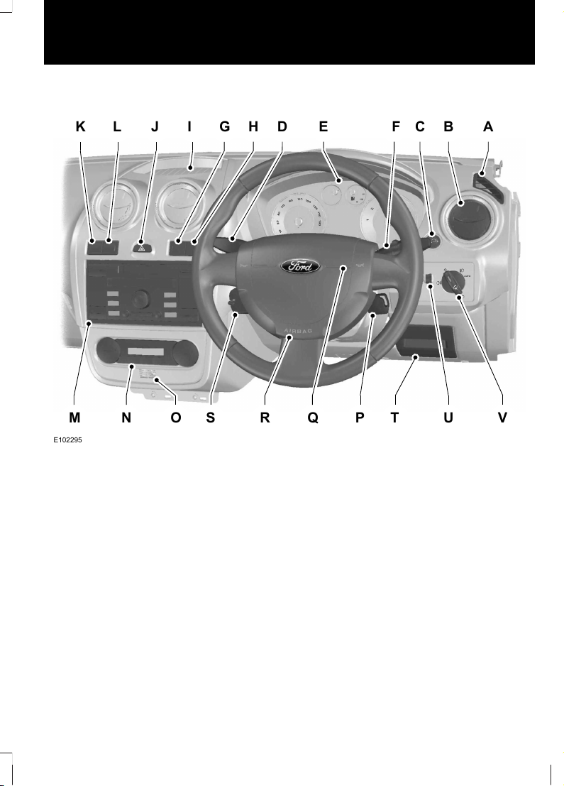
Right-hand drive
K
M O R VUTPQSN
L I H D EG BCF AJ
E102295
Window demister.A
Air vent. See Air Vents (page 58).B
Luggage compartment release.C
Main beam, direction indicators, headlamp flasher and information display
controls. See Lighting Control (page 37). See General Information (page
53).
D
Instrument cluster. See Gauges (page 49).E
Wiper lever. See Wipers and Washers (page 33).F
Heated windscreen switch. See Heated Windows and Mirrors (page 62).G
Heater rear window switch. See Heated Windows and Mirrors (page 62).H
Storage tray.I
Hazard warning flasher switch. See Hazard Warning Flashers (page 39).J
Stability control switch or coin holder. See Stability Control (page 83).K
9
At a Glance
Page 12
Airbag deactivated warning lamp or coin holder. See Disabling the passenger
airbag (page 23).
L
Audio or navigation unit. See separate handbook.M
Climate controls. See Climate Control (page 58).N
Interior temperature sensor.O
Ignition switch. See Ignition Switch (page 72).P
Horn.Q
Steering wheel adjustment lever. See Adjusting the Steering Wheel (page
31).
R
Audio controls. See Audio Control (page 31).S
Storage compartment.T
Headlamp levelling control. See Headlamp Levelling (page 39).U
Lighting controls. See Lighting (page 37).V
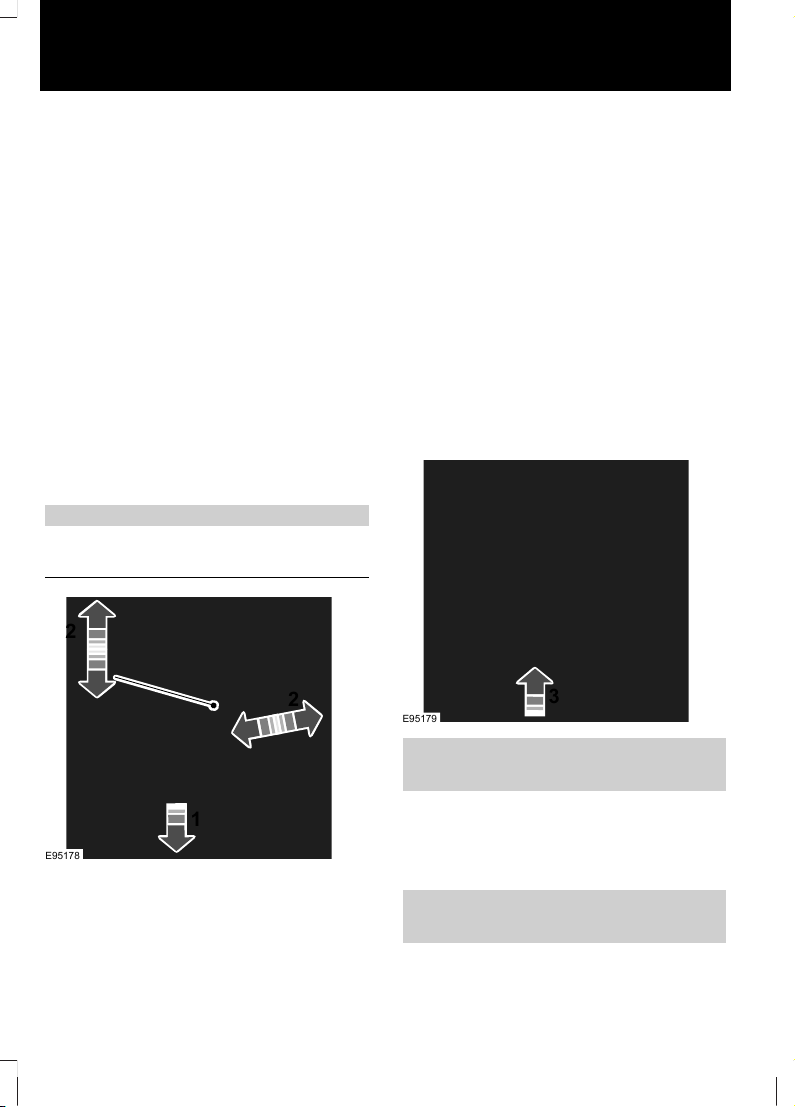
Adjusting the steering wheel
WARNING
Never adjust the steering wheel
when the vehicle is moving.
1
2
2
E95178
3
E95179
See Adjusting the Steering Wheel
(page 31).
Engine idle speed after starting
The engine may idle at a higher speed than
normal immediately after starting from
cold.
See Starting and Stopping the Engine
(page 72).
10
At a Glance
Page 13
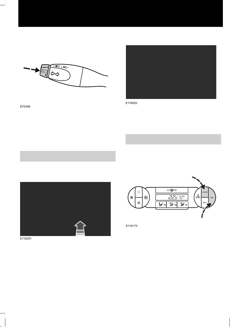
Information displays
E70436
Press the button to scroll through the
displays and hold the button to reset,
select a submenu or change a setting. The
information display will tell you whether a
short press of the button or long press of
the button is required for the various
options.
See Information Displays (page 53).
Manual climate control
Recommended settings for cooling
E116251
Open the centre and side air vents.
Direct the centre air vents upwards and the
side air vents toward the side windows.
Recommended settings for heating
E116252
Close the centre air vents and open the
side air vents.
Direct the side air vents toward the side
windows.
See Manual Climate Control (page 58).
Automatic climate control
Recommended settings for cooling
E116173
Set the temperature to 22°C (72°F).
Open the centre and side air vents.
Direct the centre air vents upwards and the
side air vents toward the side windows.
11
At a Glance
Page 14
Recommended settings for heating
E72153
Set the temperature to 22°C (72°F).
Open the centre and side air vents.
Direct the centre air vents upwards and the
side air vents toward the side windows.
See Automatic Climate Control (page
60).
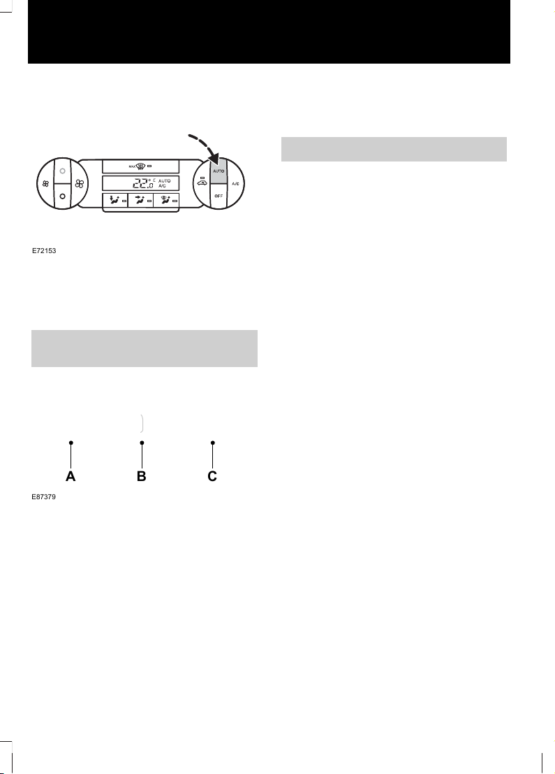
Locking and unlocking the doors
with the remote control
E87379
A B C
UnlockA
LockB
Luggage compartment lid unlockC
Locking the doors
Press button B once.
Double locking the doors
Press button B twice within three seconds.
Unlocking the luggage compartment
lid
Press button C twice within three seconds.
See Locking and Unlocking (page 27).
Audio unit
Automatic volume control (AVC)
When available, automatic volume control
(AVC) adjusts the volume level to
compensate for engine noise and road
speed noise.
1. Press the MENU button repeatedly
until an AVC display appears.
2. Use the left or right arrow button, to
adjust the AVC setting.
Changing the date and time
1. Press the CLOCK button to display the
date and time.
2. Use the left or right arrow button to
select the date or time value that you
wish to change. The selected value will
flash in the display.
3. Turn the volume control to change the
selected date or time value.
4. Use the left or right arrow button to
select additional date or time values
that you wish to change.
5. Turn the volume control to change the
selected date or time value.
6. Press the CLOCK button to exit and
save the new date and time.
12
At a Glance
Page 15
Autolamps
E72162
Note: If you have switched autolamps on,
you can only switch the main beam on when
autolamps has switched the headlamps on.
The headlamps will come on and go off
automatically depending on the ambient
light.
See Lighting (page 37).
Home safe lighting
Vehicles without autolamps
Switch the headlamps on and then switch
them off within two seconds.
Vehicles with autolamps
a. Switch autolamps on and then switch
them off within two seconds.
b. Switch autolamps off and then switch
them on within two seconds.
See Lighting (page 37).
Welcome lighting
The side and tail lamps will come on when
you unlock the doors with the remote
control. They will switch off automatically
after a short time.
See Lighting (page 37).
Autowipers
E72173
2
High sensitivity1
Low sensitivity6
See Windscreen Wipers (page 33).
Electric folding mirrors
E72184
Automatic folding
The mirrors will fold automatically when
you lock the vehicle with the remote
control. The mirrors will unfold when you
unlock the vehicle with the key or the
remote control.
See Electric exterior mirrors (page 47).
13
At a Glance
Page 16

Creating a level load floor
E91009
1 2
3
1. Lift the seat cushion.
2. Pull the locking lever and push the
seatback forwards.
3. Press the rear of the seatback
downwards.
See Rear Seats (page 65).
14
At a Glance
Page 17
CHILD SEATS
E133140
E68916
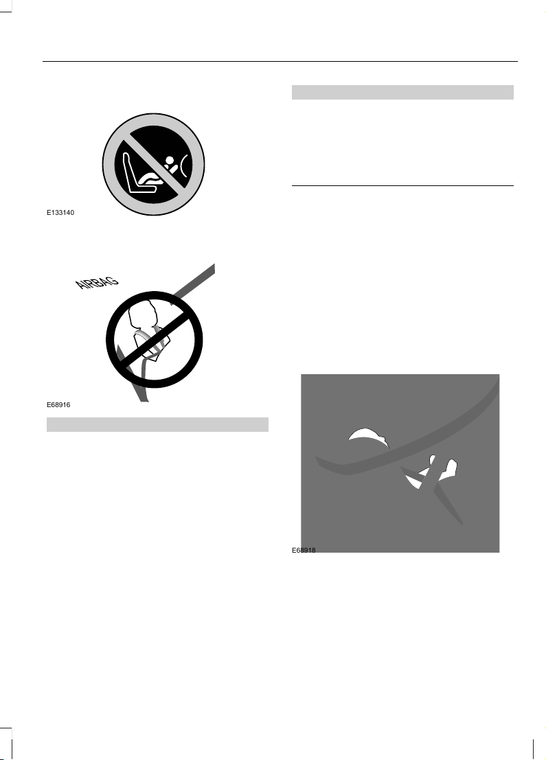
WARNINGS
Secure children that are less than
150 centimetres (59 inches) tall in a
suitable, approved child restraint, in
the rear seat.
Extreme Hazard! Do not use a
rearward facing child restraint on a
seat protected by an air bag in front
of it!
Read and follow the manufacturer’s
instructions when you are fitting a
child restraint.
Do not modify child restraints in any
way.
Do not hold a child on your lap when
the vehicle is moving.
WARNINGS
Do not leave unattended children in
your vehicle.
If your vehicle has been involved in
an accident, have the child restraints
checked by properly trained
technicians.
Note: Mandatory use of child restraints
varies from country to country.
Only child restraints certified to
ECE-R44.03 (or later) have been tested
and approved for use in your vehicle. A
choice of these are available from your
Dealer.
Child restraints for different mass
groups
Use the correct child restraint as follows:
Baby safety seat
E68918
Secure children that weigh less than 13
kilograms (29 pounds) in a rearward facing
baby safety seat (Group 0+) in the rear
seat.
15
Child Safety
Page 18
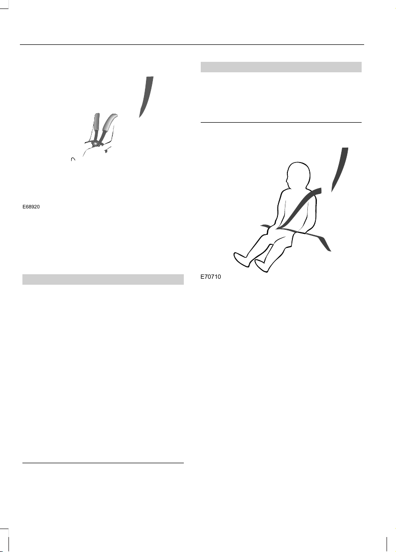
Child safety seat
E68920
Secure children that weigh between 13 and
18 kilograms (29 and 40 pounds) in a child
safety seat (Group 1) in the rear seat.
BOOSTER SEATS
WARNINGS
Do not install a booster seat or a
booster cushion with only the lap
strap of the seat belt.
Do not install a booster seat or a
booster cushion with a seat belt that
is slack or twisted.
Do not put the seat belt under your
child’s arm or behind its back.
Do not use pillows, books or towels
to boost your child’s height.
Make sure that your children sit in an
upright position.
Secure children that weigh more
than 15 kilograms (33 pounds) but
are less than 150 centimetres (59
inches) tall in a booster seat or a booster
cushion.
CAUTION
When using a child seat on a rear seat,
make sure that the child seat rests
tightly against the vehicle seat. It may
be necessary to lift or remove the head
restraint. See Head Restraints (page 66).
Booster seat (Group 2)
E70710
We recommend that you use a booster
seat that combines a cushion with a
backrest instead of a booster cushion only.
The raised seating position will allow you
to position the shoulder strap of the adult
seat belt over the centre of your child’s
shoulder and the lap strap tightly across
its hips.
16
Child Safety
Page 19
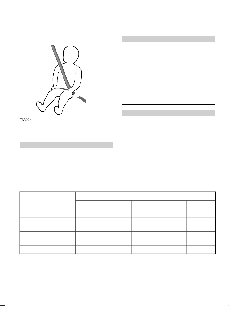
Booster cushion (Group 3)
E68924
CHILD SEAT POSITIONING
WARNINGS
Please consult your Dealer for the
latest details relating to Ford
recommended child seats.
WARNINGS
Original text according to ECE
R94.01: Extreme Hazard! Do not use
a rearward facing child restraint on
a seat protected by an air bag in front of
it!
When using a child seat with a
support leg, the support leg must
rest securely on the floor.
When using a child seat with a seat
belt, make sure that the seat belt is
not slack or twisted.
CAUTION
The child seat must rest tightly
against the vehicle seat. It may be
necessary to lift or remove the head
restraint. See Head Restraints (page 66).
Note: When using a child seat on a front
seat, always adjust the front passenger seat
to its fully rearwards position. If it proves
difficult to tighten the lap section of the seat
belt without slack remaining, adjust the
seatback to the fully upright position and
raise the height of the seat. See Manual
Seats (page 64).
Mass group categories
Seating positions 3210+0
22 - 36 kg15 - 25 kg9 - 18 kgUp to 13 kgUp to 10 kg
UF¹UF¹UF¹XX
Front passenger seat
with airbag ON
U¹U¹U¹U¹U¹
Front passenger seat
with airbag OFF
UUUUURear seats
X Not suitable for children in this mass group.
U Suitable for universal category child seats approved for use in this mass group.
17
Child Safety
Page 20

U¹ Suitable for universal category child seats approved for use in this mass group. However,
we recommend that you secure children in a government approved child seat, in the rear
seat.
UF¹ Suitable for universal category forward facing child seats approved for use in this
mass group. However, we recommend that you secure children in a government approved
child seat, in the rear seat.
18
Child Safety
Page 21
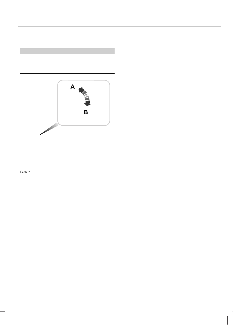
CHILD SAFETY LOCKS
WARNING
You cannot open the doors from
inside if you have put the child safety
locks on.
E73697
A
B
LockA
UnlockB
19
Child Safety
Page 22
PRINCIPLE OF OPERATION
Airbags
WARNINGS
Do not modify the front of your
vehicle in any way. This could
adversely affect deployment of the
airbags.
Original text according to ECE
R94.01: Extreme Hazard! Do not use
a rearward facing child restraint on
a seat protected by an airbag in front of it!
Wear a seat belt and keep sufficient
distance between yourself and the
steering wheel. Only when you use
the seat belt properly, can it hold you in a
position that allows the airbag to achieve
its optimum effect. See Sitting in the
Correct Position (page 64).
Have repairs to the steering wheel,
steering column, seats, airbags and
seat belts carried out by properly
trained technicians.
Keep the areas in front of the airbags
free from obstruction. Do not affix
anything to or over the airbag covers.
Do not poke sharp objects into areas
where airbags are fitted. This could
damage and adversely affect
deployment of the airbags.
Use seat covers designed for seats
with side airbags. Have these fitted
by properly trained technicians.
Note: You will hear a loud bang and see a
cloud of harmless powdery residue if an
airbag deploys. This is normal.
Note: Only wipe airbag covers with a damp
cloth.
The restraint system comprises:
• a driver airbag
• a front passenger airbag
• side airbags
• curtain airbags
• a driver seat belt pretensioner
• a front passenger seat belt
pretensioner
• crash sensors
• an airbag warning lamp
• a seat belt reminder
• an electronic control and diagnostic
unit.
You can also have your vehicle fitted with:
• an airbag deactivation switch
• an airbag deactivation warning lamp.
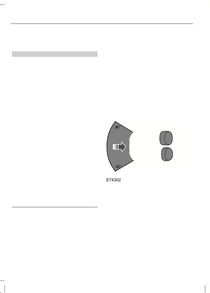
Driver and front passenger airbags
E74302
The driver and front passenger airbags will
deploy during significant frontal collisions
or collisions that are up to 30 degrees from
the left or the right. The airbags will inflate
within a few thousandths of a second and
deflate on contact with the occupants,
thus cushioning forward body movement.
During minor frontal collisions, overturns,
rear collisions and side collisions, the driver
and front passenger airbags will not
deploy.
20
Occupant protection
Page 23
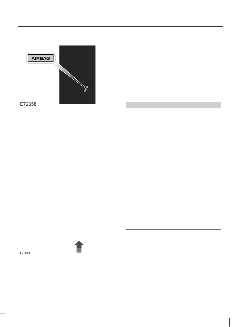
Side airbags
E72658
Side airbags are fitted inside the seatback
of the front seats. A label indicates that
side airbags are fitted to your vehicle.
The side airbags will deploy during
significant lateral collisions. Only the airbag
on the side affected by the collision will
deploy. The airbags will inflate within a few
thousandths of a second and deflate on
contact with the occupants, thus providing
protection for the chest and shoulder
areas. During minor lateral collisions,
overturns, front collisions and rear
collisions, the side airbags will not deploy.
Curtain airbags
E75004
Curtain airbags are fitted inside the trim
panels over the front and rear side
windows. Moulded badges in the B-pillar
trim panels indicate that curtain airbags
are fitted to your vehicle.
The curtain airbags will deploy during
significant lateral collisions. Only the airbag
on the side affected by the collision will
deploy. The airbag will inflate within a few
thousandths of a second and deflate on
contact with the occupants, thus providing
protection for the head. During minor
lateral collisions, front collisions, rear
collisions, or overturns the curtain airbags
will not deploy.
Seat belts
WARNINGS
Wear a seat belt and keep sufficient
distance between yourself and the
steering wheel. Only when you use
the seat belt properly, can it hold you in a
position to achieve its optimum effect. See
Sitting in the Correct Position (page
64).
Never use a seat belt for more than
one person.
Use the correct buckle for each seat
belt.
Do not use a seat belt that is slack
or twisted.
Do not wear thick clothing. The seat
belt must fit tightly around your body
to achieve its optimum effect.
Position the shoulder strap of the
seat belt over the centre of your
shoulder and position the lap strap
tightly across your hips.
The driver and front passenger seat belt
retractors are fitted with a seat belt
pretensioner. Seat belt pretensioners have
a lower deployment threshold than the
airbags. During minor collisions, it is
possible that only the seat belt
pretensioners will deploy.
21
Occupant protection
Page 24
Status after a collision
WARNING
Seat belts subjected to strain, as a
result of an accident, should be
renewed and the anchorages
checked by a properly trained technician.
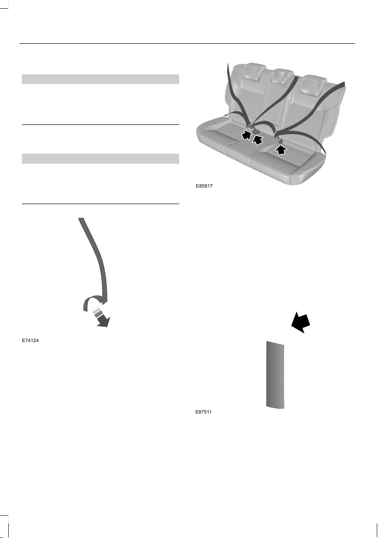
FASTENING THE SEAT BELTS
WARNING
Insert the tongue into the buckle until
you hear a distinct click. You have
not fastened the seat belt properly
if you do not hear a click.
E74124
E85817
Pull the belt out steadily. It may lock if you
pull it sharply or if the vehicle is on a slope.
Press the red button on the buckle to
release the belt. Let it retract completely
and smoothly.
SEAT BELT HEIGHT ADJUSTMENT
E87511
Note: Lifting the slider slightly while
pressing the locking button makes it easier
to release the locking mechanism.
To raise or lower, press the locking button
on the adjuster and move as necessary.
22
Occupant protection
Page 25
USING SEAT BELTS DURING PREGNANCY
E68587
WARNING
Position the seat belt correctly for
your safety and that of your unborn
child. Do not use only the lap strap
or the shoulder strap.
Position the lap strap comfortably across
your hips and low beneath your pregnant
abdomen. Position the shoulder strap
between your breasts, above and to the
side of your pregnant abdomen.
DISABLING THE PASSENGER AIRBAG
WARNING
Make sure that the passenger airbag
is disabled when using a rearward
facing child restraint on the front
passenger seat.
E71313
Fitting the passenger airbag
deactivation switch
WARNING
If you need to fit a child restraint on
a seat protected by an operational
airbag in front of it, have a passenger
airbag deactivation switch fitted. Ask your
dealer for further information.
Note: The key switch is located in the glove
compartment with an airbag deactivation
lamp in the instrument panel.
If the airbag warning lamp illuminates or
flashes when you are driving, this indicates
a malfunction. See Warning Lamps and
Indicators (page 50). Remove the child
restraint and have the system checked
immediately.
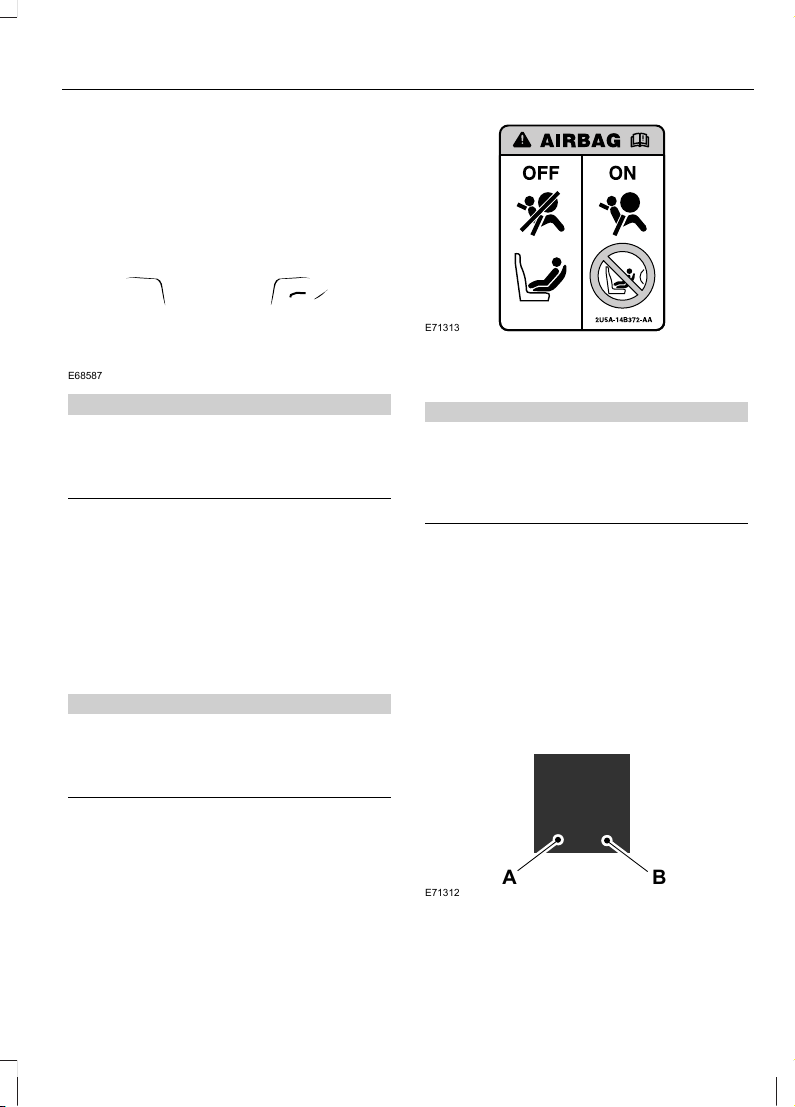
Disabling the passenger airbag
A B
E71312
DisabledA
EnabledB
23
Occupant protection
Page 26

Turn the switch to position A.
When you switch the ignition on, check that
the passenger airbag deactivation warning
lamp illuminates.
Enabling the passenger airbag
WARNING
Make sure that the passenger airbag
is enabled when you are not using a
child restraint on the front passenger
seat.
Turn the switch to position B.
24
Occupant protection
Page 27
GENERAL INFORMATION ON RADIO FREQUENCIES
CAUTIONS
The radio frequency used by your
remote control can also be used by
other short distance radio
transmissions (e.g. amateur radios,
medical equipment, wireless headphones,
remote controls and alarm systems). If the
frequencies are jammed, you will not be
able to use your remote control. You can
lock and unlock the doors with the key.
Check your vehicle is locked before
leaving it unattended. This will
safeguard against any potential
malicious frequency blocking.
Note: You could unlock the doors if you
press the buttons on the remote control
unintentionally.
The operating range between your remote
control and your vehicle varies depending
on the environment.
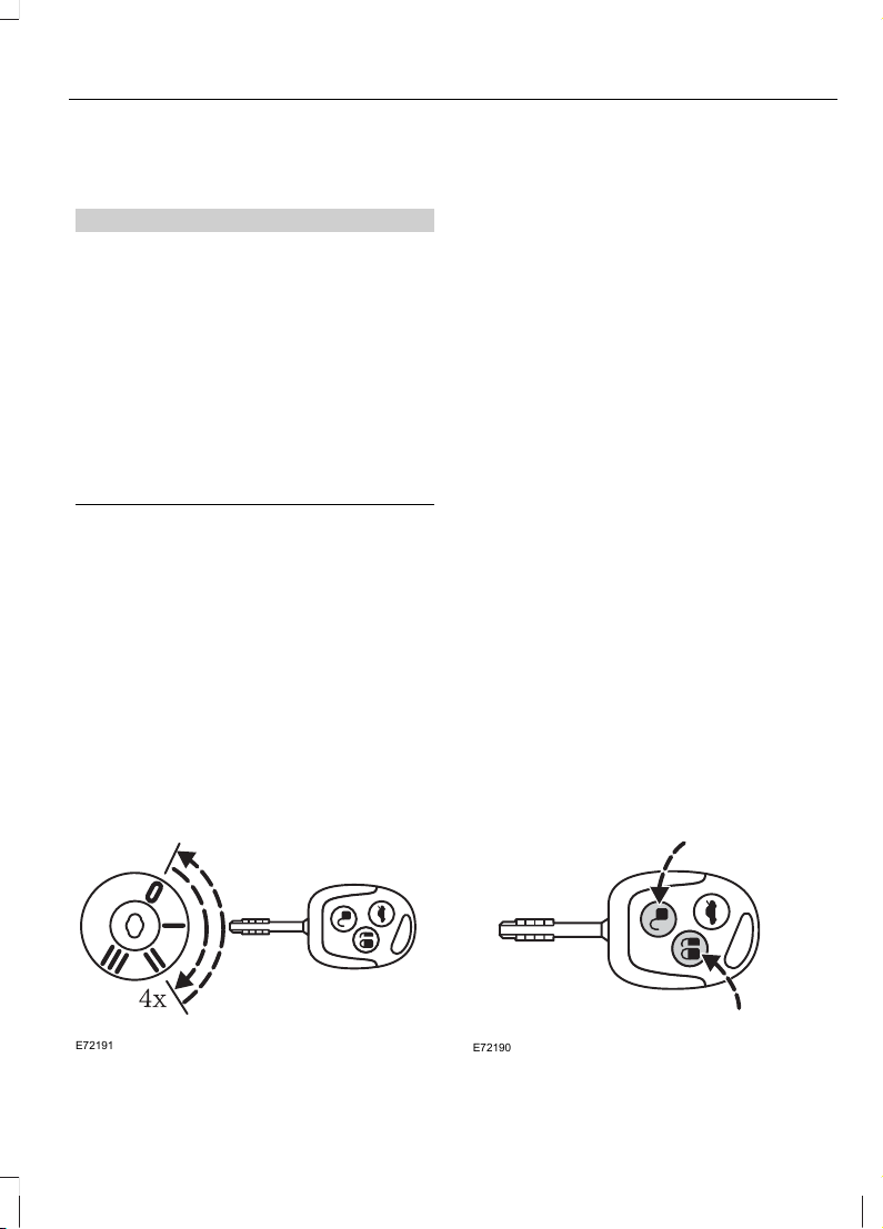
PROGRAMMING THE REMOTE CONTROL
A maximum of four remote controls
(including the ones supplied with the
vehicle) can be programmed.
E72191
To programme a new remote control:
• Turn the ignition key to position II four
times within six seconds.
• Switch off the ignition. A tone sounds
to indicate that it is now possible to
programme a new remote control.
• Press any button on a new remote
control. A tone will sound as
confirmation. Repeat this last step for
all of your remote controls, including
the original.
• Switch the ignition back on or wait for
ten seconds without programming
another remote control to end remote
control programming. Only the remote
controls which you have just
programmed are now able to lock and
unlock your vehicle.
Re-programming the unlocking
function
You can change the unlocking function so
that pressing the unlock button once
deactivates the central locking or double
locking, disarms the anti-theft alarm
system and unlocks the driver’s door.
Pressing the unlock button twice within
three seconds also unlocks the passengers’
doors.
If you want the tailgate to be locked while
driving, press the locking button on the
driver’s door to activate central locking.
E72190
25
Keys and Remote Controls
Page 28
In order to re-programme the function,
press and hold the unlock and lock buttons
simultaneously for at least four seconds
with the ignition switched off. The direction
indicators will flash twice to indicate that
the unlocking function has been
successfully re-programmed.
Pressing and holding both buttons
simultaneously for at least four seconds
again will change the function back.
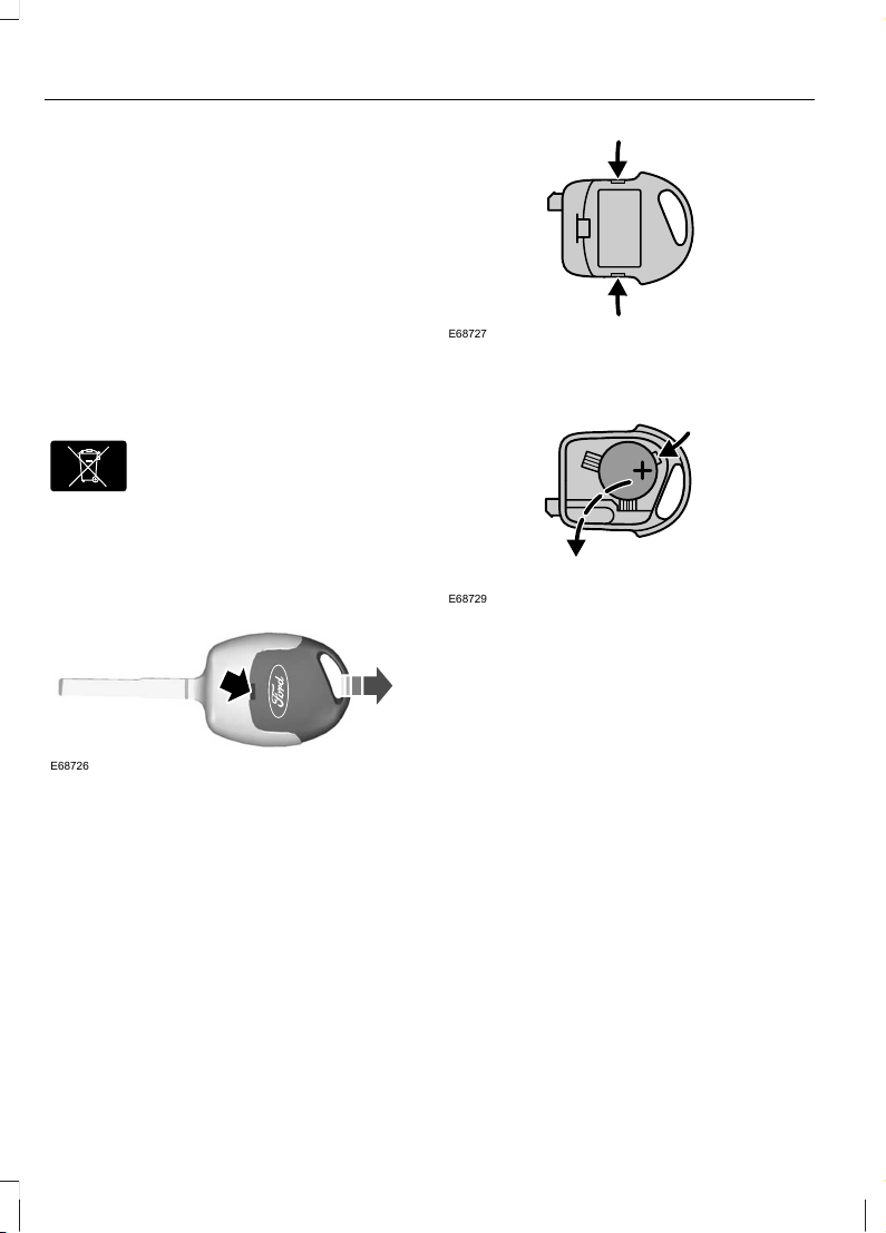
CHANGING THE REMOTE CONTROL BATTERY
E107998
Make sure that you dispose of
old batteries in an
environmentally friendly way.
Seek advice from your local authority
regarding recycling.
If the range of the transmitter in the key
decreases gradually, the battery (type 3V
CR 2032) should be replaced.
E68726
• Carefully separate the transmitter unit
from the key using a flat object (e.g. a
screwdriver) at the recess on the back.
• Carefully prise out the battery with the
flat object. Fit the new battery between
the contacts with the + sign facing
downwards. Reassemble the
transmitter unit in reverse order.
E68727
• Open the transmitter unit by separating
the retaining clips on the sides with the
flat object.
E68729
• Carefully prise out the battery with the
flat object. Fit the new battery between
the contacts with the + sign facing
downwards. Reassemble the
transmitter unit in reverse order.
26
Keys and Remote Controls
Page 29
LOCKING AND UNLOCKING
Central locking
You can only centrally lock the doors if they
are all closed.
Double locking
WARNINGS
Do not activate double locking when
persons or animals are inside the
vehicle.
You will not be able to unlock the
doors from the inside if you have
double locked them.
Double locking is a theft protection feature
that prevents someone from opening the
doors from the inside. You can only double
lock the doors if they are all closed.
Locking and unlocking
confirmation
When you unlock the doors, the direction
indicators will flash once.
When you lock the doors, the direction
indicators will flash twice.
Note: If your vehicle has double locking, the
direction indicators will only flash twice
once you have activated double locking.
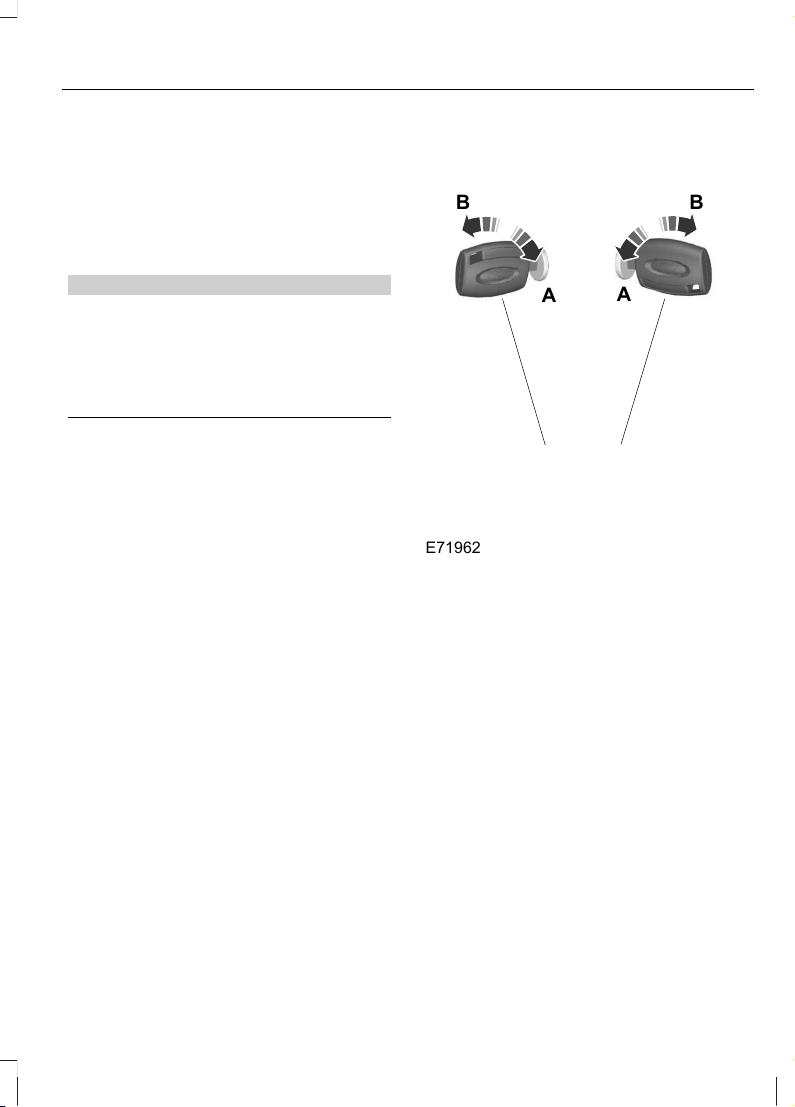
Locking and unlocking the doors
with the key
B
E71962
A
B
A
UnlockA
LockB
Double locking the doors with the key
Turn the key to the unlock position and
then the lock position within two seconds.
27
Locks
Page 30

Locking and unlocking the doors
with the remote control
E87379
A B C
UnlockA
LockB
Luggage compartment lid unlockC
Locking the doors with the remote
control
Press button B once.
Double locking the doors with the
remote control
Press button B twice within three seconds.
Unlocking the luggage compartment
lid
Press button C twice within three seconds.
Automatic relocking
The doors will relock automatically if you
do not open a door within 45 seconds of
unlocking the doors with the remote
control. The door locks and the alarm will
return to their previous state.
Reprogramming the unlocking
function
You can reprogram the unlocking function
so that only the driver's door is unlocked
or all doors are unlocked. Press the lock
and unlock buttons on the remote control
at the same time for four seconds with the
ignition switched off. The direction
indicators will flash twice as confirmation.
28
Locks
Page 31

PRINCIPLE OF OPERATION
The engine immobiliser is a theft protection
system that prevents someone from
starting the engine with an incorrectly
coded key.
CODED KEYS
Note: Do not shield your keys with metal
objects. This may prevent the receiver from
recognising your key as a valid one.
Note: Have all of your remaining keys
erased and recoded if you lose a key. Ask
your dealer for further information. Have
replacement keys recoded together with
your existing keys.
If you lose a key, you can obtain a
replacement from your Ford Dealer. If
possible, provide them with the key
number from the tag provided with the
original keys. You can also obtain
additional keys from your Ford Dealer.
ARMING THE ENGINE IMMOBILISER
The engine immobiliser is armed
automatically a short time after you have
switched the ignition off.
The indicator in the instrument cluster will
flash to confirm that the system is
operating.
DISARMING THE ENGINE IMMOBILISER
Switching on the ignition disarms the
system if the correct code is recognised.
The indicator illuminates for
approximately three seconds and then
extinguishes.
If the indicator illuminates constantly for
one minute or flashes for approximately
one minute and then repeatedly at irregular
intervals, the system did not recognise the
key code or a system fault is present.
Remove the key and try again.
If the engine does not start, a system
malfunction has occurred. Have the system
checked by an expert immediately.
29
Engine immobiliser
Page 32

ARMING THE ALARM
The system is armed as soon as the vehicle
is locked and acts as a deterrent to
unauthorised persons who attempt to
open the doors, bonnet or luggage
compartment, or remove the audio system.
Automatic arming delay
The 20 seconds arming delay begins when
the bonnet, luggage compartment and all
doors are closed and locked.
Alarm
The alarm sounds for 30 seconds if an
unauthorised person opens a door, the
load compartment or the bonnet. The
hazard warning flashers will flash for five
minutes.
Any attempt to start the engine or to
remove the audio system sounds the alarm
again.
DISARMING THE ALARM
Disarm and silence the alarm by unlocking
either of the front doors or luggage
compartment with the key.
30
Alarm
Page 33

ADJUSTING THE STEERING WHEEL
WARNING
Never adjust the steering wheel
when the vehicle is moving.
Note: Make sure that you are sitting in the
correct position. See Sitting in the Correct
Position (page 64).
1
2
2
E95178
3
E95179
WARNING
Make sure that you fully engage the
locking lever when returning it to its
original position.
AUDIO CONTROL
Select radio, CD or cassette mode on the
audio unit.
The following functions can be operated
with the remote control:
Volume
E70361
Volume up: Pull the VOL+ switch towards
the steering wheel.
Volume down: Pull the VOL− switch
towards the steering wheel.
31
Steering Wheel
Page 34

Seek
E70362
Move the SEEK switch towards the
steering wheel or the instrument panel:
• In radio mode, this will locate the next
radio station up or down the frequency
band.
• In CD mode, it will select the next or
previous track.
Mode
E70363
Briefly press the button on the side:
• In radio mode, this will locate the next
pre-set radio station.
• In CD mode, this will select the next
CD if a CD changer is fitted.
• In all modes to abort a traffic message
during broadcasting.
Press and hold the button on the side:
• In radio mode, to change the
waveband.
32
Steering Wheel
Page 35

WINDSCREEN WIPERS
A
B
C
D
E72172
Single wipeA
Intermittent wiping or
autowipers
B
Normal wipingC
High speed wipingD
Intermittent wiping
E72173
2
Select wipe interval with rotary switch: 1 =
Short time interval. 6 = Extended time
interval.
Autowipers
WARNINGS
In icy conditions, make sure that the
windscreen has been fully defrosted
before selecting autowipers.
Switch off the autowipers feature
before entering a car wash.
Replace the wiper blades as soon as
they begin to leave bands of water
and smears or when they do not
completely remove water from the
windscreen. If the blades are not replaced,
the rain sensor will continue to detect
water on the windscreen. This will result
in the wipers continuing to operate
although the majority of the windscreen is
dry.
Note: The autowipers feature is intended
for use during wet weather conditions only
and is very sensitive to anything which
touches the windscreen near to the rain
sensor. Objects such as dirt, mist or flies
hitting the windscreen in this location may
cause the wipers to wipe even though the
windscreen is mostly dry.
Note: The autowipers feature should not
be selected when it is snowing, foggy or
when the roads have been salted. In these
weather conditions, select an alternative
position if necessary.
When autowipers is selected, the wipers
will cycle once regardless of whether the
windscreen is wet or dry. Thereafter, or
when the ignition is switched on with
autowipers selected, the wipers will not
cycle until water is detected on the
windscreen. Alternatively, move the lever
to another position and then select
autowipers, or operate the washer.
33
Wipers and Washers
Page 36

The rain sensor will continuously measure
the amount of water on the windscreen
and adjust the speed of the front wipers
automatically (single wipe, intermittent,
normal or high speed wiping).
E72173
2
The sensitivity of the rain sensor is set
using the rotary control:
1 = High sensitivity: The wipers will wipe
even if only a small amount of water is
detected on the windscreen.
6 = Low sensitivity: The wipers will only
wipe when a larger amount of water is
detected on the windscreen.
WINDSCREEN WASHERS
E72174
WARNING
Do not operate the windscreen
washer for more than 10 seconds or
when the reservoir is empty.
REAR WINDOW WIPER AND WASHERS
Intermittent wiping
E72175
Pull the lever towards the steering wheel.
Reverse gear wipe
The rear wiper will be activated
automatically when selecting reverse gear,
if
• the rear wiper is not already switched
on,
• the wiper lever is in position C, or D
• in position B and the front wipers are
operating.
The rear wiper will follow the front wiper
interval (at intermittent or normal speed).
34
Wipers and Washers
Page 37

Washer
E72176
WARNING
Do not operate the washer for more
than 10 seconds at a time, and never
when the reservoir is empty.
Pull the lever fully towards the steering
wheel and hold it to operate the washer.
The washer will operate in conjunction with
the wipers.
The washer jet for the rear window is
located on the roof above the rear window.
CHECKING THE WIPER BLADES
E66644
Run the tip of your fingers over the edge of
the blade to check for roughness.
Clean the wiper blade lips with water
applied with a soft sponge.
CHANGING THE WIPER BLADES
E66645
5
2
4
3
1
35
Wipers and Washers
Page 38

Lift the wiper arm and position the wiper
blade at a right angle to the wiper arm. To
remove, press the retaining clip in the
direction of the arrow, disengage the wiper
blade and pull it off the arm in the opposite
direction.
36
Wipers and Washers
Page 39

LIGHTING CONTROL
Lighting control positions
A
B
C
E72161
OffA
Side and tail lampsB
HeadlampsC
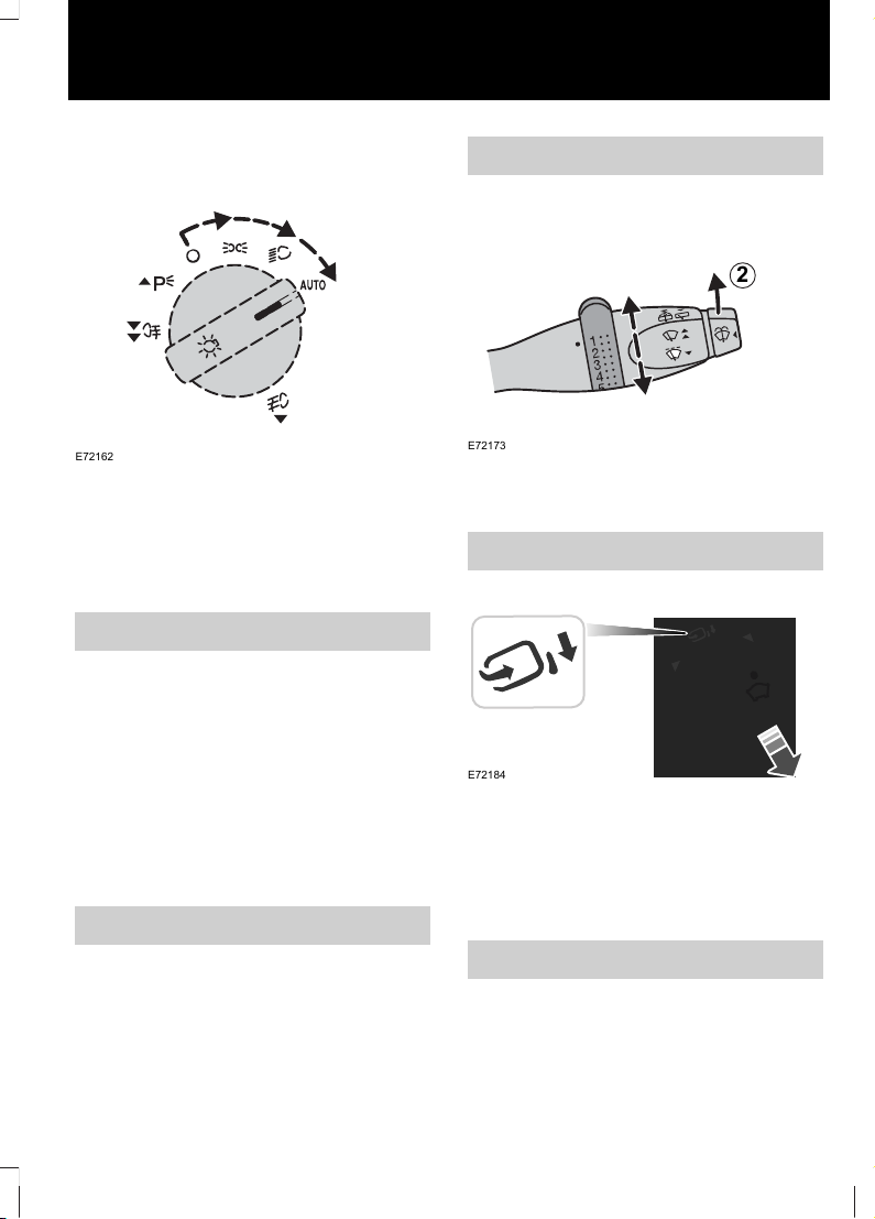
Autolamps
E72162
Note: If you have switched autolamps on,
you can only switch the main beam on when
autolamps has switched the headlamps on.
The headlamps will come on and go off
automatically depending on the ambient
light.
Home safe lighting
You can switch home safe lighting on up
to 10 minutes after you have switched the
ignition off.
Vehicles without autolamps
Switch the headlamps on and then switch
them off within two seconds.
Vehicles with autolamps
a. Switch autolamps on and then switch
them off within two seconds.
b. Switch autolamps off and then switch
them on within two seconds.
Welcome lighting
The side and tail lamps will come on when
you unlock the doors with the remote
control. They will switch off automatically
after a short time.
Main/dipped beam
E72168
Pull the lever fully towards the steering
wheel to switch between main and dipped
beam.
37
Lighting
Page 40

Headlamp flasher
E72168
Pull the lever slightly towards the steering
wheel.
FRONT FOG LAMPS
E72163
Note: It is not possible to switch on the
front fog lamps when the lighting switch is
set to AUTO. To switch on the front fog
lamps, switch off the autolamps feature.
Switch on the headlamps 1 and pull out
the control switch one position 2.
The front fog lamps should be used only
when visibility is considerably restricted by
fog, snow or rain.
REAR FOG LAMPS
1
2
E72164
WARNING
The rear fog lamps may only be used
when visibility is restricted to less
than 50 m and must not be used
when it is raining or snowing.
Note: On vehicles not equipped with front
fog lamps the control switch can be pulled
out only one position.
Note: It is not possible to switch on the rear
fog lamps when the lighting switch is set to
AUTO. To switch on the rear fog lamps,
switch off the autolamps feature.
Switch on the exterior lamps 1 and pull out
the control two positions 2.
38
Lighting
Page 41

HEADLAMP LEVELLING
E65990
You can adjust the level of the headlamp
beams according to the vehicle load.
Recommended headlamp levelling switch positions
Switch positionLoad in luggage
compartment
Load
Second row seatsFront seats
0--1-2
1-31-2
1.5
Max
1
31-2
2
Max
1
-1
1
See Vehicle Identification Plate (page 126).
HAZARD WARNING FLASHERS
Note: Depending on applicable laws and
regulations in the country for which your
vehicle was originally built, the hazard
warning flashers may flash if you brake
heavily.
E71943
For item location: See At a Glance (page
8).
39
Lighting
Page 42

DIRECTION INDICATORS
E72167
Briefly tap the lever up or down and the
direction indicators will flash three times.
INTERIOR LAMPS
Courtesy lamp
C
B
A
E71945
OffA
Door contactB
OnC
E91006
A B C
A B C
OffA
Door contactB
OnC
40
Lighting
Page 43

If you set the switch to position B, the
courtesy lamp will come on when you
unlock or open a door or the tailgate. If you
leave a door open with the ignition switch
off, the courtesy lamp will go off
automatically after some time to prevent
the vehicle battery from discharging. To
switch it back on, switch on the ignition for
a short time.
The courtesy lamp will also come on when
you switch off the ignition. It will go off
automatically after a short time or when
you start or restart the engine.
If you set the switch to position C with the
ignition switch off, the courtesy lamp will
come on. It will go off automatically after
a short time to prevent the vehicle battery
from discharging. To switch it back on,
switch on the ignition for a short time.
Reading lamps
E71946
A
B
E72900
OffA
OnB
REMOVING A HEADLAMP
1. Open the bonnet. See Opening and
Closing the Bonnet (page 101).
E90592
4
5
1
2
3
2. Remove the screws.
41
Lighting
Page 44

3
E90593
CAUTION
Do not pull the bumper more than 10
mm from its original position.
3. Carefully pull the bumper towards the
front of the vehicle and remove the
screw.
4. Disconnect the electrical connector
and remove the headlamp.
CAUTION
When fitting the headlamp, take care
not to damage the locating points.
Note: When fitting the headlamp, make
sure that you fully engage the headlamp in
the fixing points.
CHANGING A BULB
WARNINGS
Switch the lights and the ignition off.
Let the bulb cool down before
removing it.
CAUTIONS
Do not touch the glass of the bulb.
Only fit bulbs of the correct
specification. See Bulb
Specification Chart (page 46).
Note: The following instructions describe
how to remove the bulbs. Fit replacement
in the reverse order unless otherwise stated.
Headlamp main and dipped beam
1. Remove the headlamp. See
Removing a Headlamp (page 41).
E91017
2. Remove the cover.
3. Disconnect the electrical connector.
4. Release the clip and remove the bulb.
Side lamps
1. Remove the headlamp. See
Removing a Headlamp (page 41).
42
Lighting
Page 45

E91018
2. Remove the cover.
3. Carefully prise out the bulb holder.
4. Remove the bulb.
Front direction indicators
1. Remove the headlamp. See
Removing a Headlamp (page 41).
E91016
2. Turn the bulb holder anticlockwise and
remove it.
3. Gently press the bulb into the bulb
holder, turn it anticlockwise and
remove it.
Side repeaters
2
1
3
E78869
1. Carefully remove the side repeater.
2. Hold the bulb holder, turn the housing
anticlockwise and remove it.
3. Remove the bulb.
Front fog lamps
E91019
1. Disconnect the electrical connector.
2. Turn the bulb holder anticlockwise and
remove it.
Rear lamps
1. Open the tailgate.
43
Lighting
Page 46

E91020
2. From inside the luggage compartment,
remove the wing nut on the back of the
rear lamp.
3. Remove the screws and remove the
rear lamp assembly.
4. Release the clips and remove the bulb
holder.
A
B
C
D
E91021
5. Gently press the bulbs into the bulb
holder, turn them anticlockwise and
remove them.
Central high mounted stop lamp
2 3
4
E90600
1. Open the tailgate.
2. Remove the rubber grommet.
3. Release the clips using a flat-bladed
screwdriver and remove the lamp.
4. Unclip the bulb holder and remove the
bulb.
44
Lighting
Page 47

Number plate lamp
E90601
1. Loosen the screws and remove the
lamp.
2. Remove the bulb.
Interior lamp
E73091
1
2
E73092
3
1. Carefully prise out the lamp.
2. Remove the lens.
3. Remove the bulb.
Reading lamps
E73938
1
2
E73939
3
1. Carefully prise out the lamp.
2. Turn the bulb holder anticlockwise and
remove it.
3. Remove the bulb.
45
Lighting
Page 48

Luggage compartment lamp
E72784
1. Carefully prise out the lamp.
2. Remove the bulb.
BULB SPECIFICATION CHART
Rating (watt)SpecificationBulb
21PY21WFront direction indicator
5Side lamp
55/60H4Headlamp
5Side repeater
55H11Front fog lamp
5P21/5WBrake and tail lamp
21P21WRear direction indicator
21P21WReversing lamp
21P21WRear fog lamp
16Central high mounted stop
lamp
5ZW5Number plate lamp
10Interior lamp
5Reading lamp
5Luggage compartment lamp
46
Lighting
Page 49

POWER WINDOWS
WARNING
Do not operate the electric windows
unless they are free from obstruction.
Note: If you operate the switches often
during a short period of time, the system
might become inoperable for a certain time
to prevent damage due to overheating.
E93505
Switch on the ignition to operate the
electric windows.
To open the driver’s window
automatically
Press the switch to the second action point
and release it. Press it again to stop the
window.
EXTERIOR MIRRORS
WARNING
Do not overestimate the distance of
the objects that you see in the
convex mirror. Objects seen in
convex mirrors will appear smaller and
further away than they actually are.
Manual folding mirrors
Folding
Push the mirror towards the door window
glass.
Unfolding
Make sure that you fully engage the mirror
in its support when returning it to its
original position.
ELECTRIC EXTERIOR MIRRORS
E66485
A
B
C
Left-hand mirrorA
OffB
Right-hand mirrorC
Electric exterior mirrors are fitted with a
heating element that will defrost or demist
the mirror glass. They will switch on
automatically when you switch the heated
rear window on.
47
Windows and Mirrors
Page 50

Mirror tilting positions
E66486
upA
rightB
downC
leftD
Electric folding mirrors
E72184
Automatic folding
The mirrors will fold automatically when
you lock the vehicle with the remote
control. The mirrors will unfold when you
unlock the vehicle with the key or the
remote control.
48
Windows and Mirrors
Page 51

GAUGES
E89015
BA C D
E
TachometerA
Engine coolant temperature gaugeB
Fuel gaugeC
SpeedometerD
Information displayE
Engine coolant temperature gauge
All vehicles
Shows the temperature of the engine
coolant. At normal operating temperature,
the needle will remain in the centre section.
CAUTION
Do not restart the engine until the
cause of overheating has been
resolved.
If the needle enters the red section, the
engine is overheating. Stop the engine,
switch the ignition off and determine the
cause once the engine has cooled down.
49
Instrument Cluster
Page 52

Vehicles with an information display
In addition, a warning message will appear
in the display.
Fuel gauge
The arrow adjacent to the fuel pump
symbol tells you on which side of your
vehicle the fuel filler cap is located.
WARNING LAMPS AND INDICATORS
The following warning lamps and
indicators illuminate when the ignition is
switched on:
• ABS
• Airbag
• Brake system
• Door open
• Engine
• Frost
• Ignition
• Oil pressure
• Power steering
• Powertrain
• Stability control (ESP).
If a warning or indicator lamp does not
illuminate when the ignition is switched
on, it indicates a malfunction. Have the
system checked by properly trained
technician.
ABS warning lamp
If it illuminates when you are
driving, this indicates a
malfunction. You will continue
to have normal braking (without ABS).
Have the system checked by a properly
trained technician as soon as possible.
Airbag warning lamp
If it illuminates when you are
driving, this indicates a
malfunction. Have the system
checked by a properly trained technician.
Brake system lamp
It illuminates when the parking
brake is engaged.
WARNING
Reduce your speed gradually and
stop your vehicle as soon as it is safe
to do so. Use your brakes with care.
If it illuminates when you are driving, check
that the parking brake is not engaged. If
the parking brake is not engaged, this
indicates a malfunction. Have the system
checked by a properly trained technician
immediately.
Direction indicator
Flashes during operation. A
sudden increase in the rate of
flashing warns of a failed
indicator bulb. See Changing a Bulb
(page 42).
Door open warning lamp
Illuminates when the ignition is
switched on and remains on if
any door, the bonnet or the
luggage compartment is not closed
properly.
50
Instrument Cluster
Page 53

Engine warning lamp
If it illuminates with the engine
running, this indicates a
malfunction. If it flashes when
you are driving, reduce the speed of your
vehicle immediately. If it continues to
flash, avoid heavy acceleration or
deceleration. Have the system checked by
a properly trained technician immediately.
Front fog lamp indicator
It will illuminate when you switch
the front fog lamps on.
Frost warning lamp
It will illuminate and glow amber
when the outside air
temperature is between 4ºC
(39ºF) and 1°C (34°F). It will glow red
when the temperature is below 1°C (34°F).
Glow plug indicator
See Starting a Diesel Engine
(page 73).
Headlamp indicator
It will illuminate when you switch
the headlamp dipped beam or
the side and tail lamps on.
Ignition warning lamp
If it illuminates when you are
driving, this indicates a
malfunction. Switch off all
unnecessary electrical equipment. Have
the system checked by a properly trained
technician immediately.
Low fuel level warning lamp
If it illuminates, refuel as soon as
possible.
Main beam indicator
It will illuminate when you switch
the headlamp main beam on. It
will flash when you use the
headlamp flasher.
Oil pressure warning lamp
CAUTION
Do not resume your journey if it
illuminates despite the level being
correct. Have the system checked by
a properly trained technician immediately.
If it stays on after starting or
illuminates when driving, this
indicates a malfunction. Stop
your vehicle as soon as it is safe to do so
and switch the engine off. Check the engine
oil level. See Engine Oil Check (page 107).
Overdrive indicator
It will illuminate when you switch
overdrive off.
Power steering warning lamp
Illuminates to indicate a
malfunction of the power
steering system. Full steering will
be maintained but you will need to exert
greater force on the steering wheel. Have
the system checked by a properly trained
technician as soon as possible.
51
Instrument Cluster
Page 54

Powertrain warning lamp
Vehicles with an automatic
transmission
If the powertrain warning lamp
comes on when the engine is
running, this indicates either a
malfunction or a high transmission
temperature. Stop your vehicle as soon as
it is safe to do so and carry out the
following:
1. Select P or N and allow the engine to
idle for 10 minutes.
2. Switch the ignition off and restart the
engine.
If the powertrain warning lamp comes on,
switch the ignition off and have the
transmission checked before continuing
your journey.
If the powertrain warning lamp does not
come on, continue your journey and have
the transmission checked as soon as
possible.
Vehicles with a 5-speed manual
transmission or Durashift EST
If the powertrain warning lamp
comes on when the engine is
running, this indicates a
malfunction. The engine will continue to
run but it will have limited power. Have this
checked as soon as possible.
If the powertrain warning lamp flashes
when the engine is running, this indicates
a malfunction. Stop your vehicle as soon
as it is safe to do so. Have this checked
before continuing your journey.
Rear fog lamp indicator
It will illuminate when you switch
the rear fog lamps on.
Stability control (ESP) warning
lamp
While driving, it flashes during
activation of the system. After
switching on the ignition, if it
does not illuminate or illuminates
continuously while driving, this indicates a
malfunction. During a malfunction, the
system switches off. Have the system
checked by a properly trained technician
as soon as possible.
If you switch ESP off, the warning lamp will
illuminate. The lamp will go out when you
switch the system back on or when you
switch the ignition off.
52
Instrument Cluster
Page 55

GENERAL INFORMATION
WARNING
Do not operate the information
display controls when the vehicle is
moving.
Note: The information display will remain
on for several minutes after you switch off
the ignition.
Note: If Sh on or SHIP ON is displayed, the
vehicle shipping mode is switched on. Have
your dealer switch off the vehicle shipping
mode.
Type 1 information display
E91003
E D
A
B
C
Distance to empty or clockA
TripmeterB
OdometerC
Select buttonD
Reset buttonE
Press the select button to scroll through
the displays.
Setting the time
E91004
Note: You can only set the time through the
audio unit on some vehicles. See Setting
the clock and date on the audio unit (page
137).
1. Press the select button until the time
flashes in the display.
2. Press the select button to set the time.
Type 2 information display
A
F
B
C
E
E91005
D
Selected gearA
Clock, radio station or CD trackB
Outside air temperatureC
TripmeterD
53
Information Displays
Page 56

OdometerE
Message indicatorF
You can change the settings of various
functions through the information display.
The information display also provides
information messages.
E70436
Press the button to scroll through the
displays and hold the button to rest, select
a submenu or change a setting. The
information display will tell you whether a
short press of the button or long press of
the button is required for the various
options.
Message indicator
The message indicator will come on to
supplement some messages. It will be red
or amber depending on the severity of the
message and will remain on until the cause
of the message has been rectified.
Display definitions
Distance to empty
Indicates the approximate distance that
your vehicle will travel on the fuel in the
fuel tank.
Average speed
Indicates the average speed of your vehicle
since the last reset.
Average fuel
Indicates the average fuel consumption of
your vehicle since the last reset.
Fuel economy
Indicates the current fuel consumption of
your vehicle.
PERSONALISED SETTINGS
You can change the settings of various
functions through the information display.
Unlocking the doors with the
remote control
You can set the unlocking function to
unlock the driver side front door only or to
unlock all of the doors.
Direction indicators
You can set the direction indicators to flash
only three times when you tap the direction
indicator level.
Audio display
You can set the information display to
display certain audio unit information.
Hazard warning flashers
You can set the hazard warning flashers
to flash automatically when you brake
heavily.
Audible warnings
You can switch off some of the audible
warnings.
Language
You can set the display to your preferred
language.
54
Information Displays
Page 57

INFORMATION MESSAGES
E70436
Press the button to acknowledge and
remove some messages from the
information display. Other messages will
be removed automatically after a short
time. Messages will remain active until the
cause has been rectified.
MeaningMessage indicatorMessage
This indicates a malfunction in one of the
brake circuits. Check the brake fluid level.
See Brake and Clutch Fluid Check (page
108). If the ABS warning lamp or the stability
control warning lamp also come on, this
indicates a malfunction. Stop your vehicle
as soon as it is safe to do so and have this
checked before continuing you journey.
RedLOW BRAKE FLUID
LEVEL
The engine is overheating. Stop the engine,
switch the ignition off and determine the
cause once the engine has cooled down.
RedHIGH ENGINE
TEMPERATURE
The transmission system has malfunctioned. Vehicles with an automatic
transmission: Stop your vehicle as soon
as it is safe to do so. Select P or N and let
the engine idle for 10 minutes. Switch the
ignition off and then restart the engine. If
RedTRANSMISSION
MALFUNCTION
the message is still displayed, switch the
ignition off and have this checked before
continuing your journey. If the message is
no longer displayed, you can continue your
journey and have this checked as soon as
possible. Vehicles with a Durashift EST
transmission: Stop your vehicle as soon
as it is safe to do so. Switch the ignition off
and have this checked before continuing
your journey.
55
Information Displays
Page 58

MeaningMessage indicatorMessage
The transmission system has malfunctioned. Avoid heavy acceleration or deceleration. The transmission will continue to
operate but you will notice some unusual
conditions. Have this checked as soon as
possible.
AmberTRANSMISSION
MALFUNCTION
The power steering system has malfunctioned. You will need to use greater force
to turn the steering wheel. Have this
checked as soon as possible.
RedSTEERING ASSIST
FAILURE
The engine system has malfunctioned. Stop
your vehicle as soon as it is safe to do so.
Switch the ignition off and have this
checked before continuing your journey.
RedENGINE SYSTEM
FAULT
The engine system has malfunctioned.
Avoid heavy acceleration or deceleration.
The engine will continue to run but it will
have limited power. Have this checked as
soon as possible.
AmberENGINE SYSTEM
FAULT
The outside air temperature is below 1°C
(34°F).
RedLOW OUTSIDE
TEMPERATURE
The outside air temperature is between 4°C
and 1°C (39°F and 34°F).
AmberLOW OUTSIDE
TEMPERATURE
Vehicles with an automatic transmission: The transmission is overheating. Stop
your vehicle as soon as it is safe to do so.
Select P or N and let the engine idle for 10
minutes. Switch the ignition off and then
restart the engine. If the message is still
displayed, switch the ignition off and have
this checked before continuing your journey.
If the message is no longer displayed, you
can continue your journey and have this
checked as soon as possible.
AmberTRANSMISSION
HOT MODE
A left-hand side indicator bulb has failed.AmberLEFT INDICATOR
BULB FAILURE
A right-hand side indicator bulb has failed.AmberRIGHT INDICATOR
BULB FAILURE
56
Information Displays
Page 59

MeaningMessage indicatorMessage
The driver side front door is open.AmberDRIVER DOOR
OPEN
The driver side rear door is open.AmberDRIVER SIDE REAR
DOOR OPEN
The passenger side front door is open.AmberPASSENGER DOOR
OPEN
The passenger side rear door is open.AmberPASSENGER SIDE
REAR DOOR OPEN
The tailgate is open.AmberBOOT OPEN
The bonnet is open.AmberBONNET OPEN
The remote control battery is low. Have this
checked as soon as possible.
AmberREMOTE KEY
BATTERY LOW
Autolamps or autowipers have malfunctioned. Have this checked as soon as
possible.
FAILURE AUTO
LAMP/WIPER
57
Information Displays
Page 60

PRINCIPLE OF OPERATION
Outside air
Keep the air intakes forward of the
windscreen free from obstruction (snow,
leaves etc.) to allow the climate control
system to function effectively.
Recirculated air
CAUTION
Prolonged use of recirculated air may
cause the windows to mist up. If the
windows mist up, follow the settings
for defrosting and demisting the
windscreen.
The air currently in the passenger
compartment will be recirculated. Outside
air will not enter the vehicle.
Heating
Heating performance depends on the
temperature of the engine coolant.
Air conditioning
Note: The air conditioning operates only
when the temperature is above 4ºC (39ºF).
Note: If you use the air conditioning, the
fuel consumption of your vehicle will be
higher.
Air is directed through the evaporator
where it is cooled. Humidity is extracted
from the air to help keep the windows free
of mist. The resulting condensation is
directed to the outside of the vehicle and
it is therefore normal if you see a small
pool of water under your vehicle.
General information on controlling
the interior climate
Fully close all the windows.
Warming the interior
Direct the air towards your feet. In cold or
humid weather conditions, direct some of
the air towards the windscreen and the
door windows.
Cooling the interior
Direct the air towards your face.
AIR VENTS
E71942
MANUAL CLIMATE CONTROL
Blower
E90444
OffA
Note: If you switch the blower off, the
windscreen may mist up.
58
Climate Control
Page 61

Temperature control
E90445
ColdBlue
WarmRed
Air distribution control
B
CE
F
A
D
E90446
WindscreenA
Footwell and windscreenB
Face levelC
Face level and footwellD
FootwellE
Face level, windscreen and
footwell
F
You can set the air distribution control to
any position between the symbols.
A small amount of air is always directed
towards the windscreen.
Defrosting and demisting the
windscreen
E90447
If necessary, switch the heated windows
on. See Heated Windows and Mirrors
(page 62).
Ventilation
E90448
Heating the interior quickly
E90449
Switching the air conditioning on
and off
59
Climate Control
Page 62

If you turn the blower off, the air
conditioning will turn off. When you turn
the blower on again, the air conditioning
will come on automatically.
Recirculated air
E73059
Cooling with outside air
E90450
Cooling the interior quickly
E90451
Reducing interior air humidity
E90452
AUTOMATIC CLIMATE CONTROL
E72153
The system controls the temperature,
amount and distribution of the air flow
automatically and adjusts them according
to the driving and weather conditions.
Pressing the AUTO button once switches
on the auto mode.
Note: Avoid adjusting the settings when
the vehicle interior is extremely hot or cold.
The automatic climate control adjusts to
the current circumstances automatically.
For the system to function properly, the side
and centre vents should be fully open.
Note: The sunload sensor is located on top
of the instrument panel. Do not cover the
sensor with any objects.
Note: At low outside temperatures, when
the system is in auto mode, the air stream
will be directed to the windscreen and the
side windows as long as the engine is cold.
60
Climate Control
Page 63

Setting the temperature
E72154
Reduces temperatureBlue
Increases temperatureRed
You can set the temperature between 16°C
(61°F) and 28°C (82°F) in steps of 0.5°C
(1°F). In position LO, 16°C (61°F), the
system will switch to permanent cooling.
In position HI, 28°C (82°F), the system will
switch to permanent heating.
Blower
Use the buttons to adjust the
blower speed. The blower
setting is indicated in the
display. To return to auto mode, press the
AUTO button.
Air distribution
E70308
A B C
FootwellA
Face levelB
WindscreenC
Note: When you select windscreen
defrosting and demisting, A, B and C switch
off automatically and the air conditioning
switches on. Outside air will flow into the
vehicle. You cannot select recirculated air.
Windscreen defrosting and
demisting
E70309
Press the windscreen defrosting
and demisting button. Outside
air will flow into the vehicle. Air
conditioning is automatically selected. As
long as the air distribution is set to this
position, you cannot select recirculated air.
The blower speed and the temperature
control operate automatically and cannot
be adjusted manually. The blower is set to
high speed and the temperature to HI.
When you select windscreen defrosting
and demisting, the heated screens switch
on automatically and switch off after a
short time.
Press the windscreen defrosting and
demisting button again to return to the
previous settings.
Switching the air conditioning on
and off
Press the A/C button to turn
the air conditioning on and off.
Recirculated air
Press the recirculated air button
to toggle between outside air
and recirculated air.
Note: When the system is in auto mode and
the interior and exterior temperatures are
quite hot, the system selects recirculated
air automatically to maximise cooling of the
interior. Once the selected temperature is
reached, the system will reselect outside air
automatically.
61
Climate Control
Page 64

Switching the automatic climate
control on and off
E72157
Press the OFF button.
When switched off, the heating, ventilation
and air conditioning system is switched off
and recirculated air is selected.
HEATED WINDOWS AND MIRRORS
Heated windows
Use the heated windows to defrost or
demist the windscreen or rear window.
Note: The heated windows operate only
when the engine is running.
Heated windscreen
E72506
Heated rear window
E72507
Heated exterior mirrors
Electric exterior mirrors are fitted with a
heating element that will defrost or demist
the mirror glass. They will switch on
automatically when you switch the heated
rear window on.
AUXILIARY HEATER
Diesel auxiliary heater (depending
on country)
The diesel auxiliary heater (PTC electrical
heater) aids in warming the engine and the
interior compartment on vehicles with
diesel engines. It is switched on or off
automatically depending on the outside
temperature, the coolant temperature and
the alternator load.
SUNROOF
E90558
62
Climate Control
Page 65

E72189
63
Climate Control
Page 66

SITTING IN THE CORRECT POSITION
E68595
WARNINGS
Do not adjust the seats when the
vehicle is moving.
Only when you use the seat belt
properly, can it hold you in a position
that allows the airbag to achieve its
optimum effect.
When you use them properly, the seat,
head restraint, seat belt and airbags will
provide optimum protection in the event
of a collision. We recommend that you:
• sit in an upright position with the base
of your spine as far back as possible.
• do not recline the seatback more than
30 degrees.
• adjust the head restraint so that the
top of it is level with the top of your
head and as far forwards as possible,
remaining comfortable.
• keep sufficient distance between
yourself and the steering wheel. We
recommend a minimum of 250
millimetres (10 inches) between your
breastbone and the airbag cover.
• hold the steering wheel with your arms
slightly bent.
• bend your legs slightly so that you can
press the pedals fully.
• position the shoulder strap of the seat
belt over the centre of your shoulder
and position the lap strap tightly across
your hips.
Make sure that your driving position is
comfortable and that you can maintain full
control of your vehicle.
MANUAL SEATS
Moving the seats backwards and
forwards
1
2
2
E74816
WARNING
Rock the seat backwards and
forwards after releasing the lever to
make sure that it is fully engaged in
its catch.
64
Seats
Page 67

Adjusting the height of the driver’s
seat
E68895
Adjusting the angle of the
seatback
E74819
Folding the passenger seat
forwards
WARNINGS
Do not drive with the passenger seat
folded forwards if the rear seat
directly behind it is occupied.
Do not drive with items on the folded
seatback.
E68896
1. Fold the seat forwards.
E91008
2. Turn the wheel until the seatback is
horizontal.
Pull the locking lever to return the seatback
to the vertical position. Make sure that the
seatback is securely latched in position.
REAR SEATS
WARNINGS
Make sure that the seats and the
seatbacks are secure and fully
engaged in their catches.
65
Seats
Page 68

WARNINGS
When folding the seatbacks down,
take care not to get your fingers
caught between the seatback and
seat frame.
When folding the seatbacks up,
make sure that the belts are visible
to an occupant and not caught
behind the seat.
CAUTION
Lower the head restraints.
Folding the seatbacks down
1
2
1
E86611
1. Pull the unlock levers.
2. Push the seatback forwards.
Creating a level load floor
E91009
1 2
3
1. Lift the seat cushion.
2. Pull the locking lever and push the
seatback forwards.
3. Press the rear of the seatback
downwards.
HEAD RESTRAINTS
E75767
66
Seats
Page 69

E81584
Adjusting the head restraint
WARNING
Raise rear head restraint when the
rear seat is occupied by a passenger
or a child restraint.
Adjust the head restraint so that the top
of it is level with the top of your head.
Removing the head restraint
Press the locking buttons and remove the
head restraint.
HEATED SEATS
Driver side
E90906
Passenger side
E90907
CAUTION
Operating the heated seats with the
engine off will drain the battery.
The heated seats will operate when the
ignition switch is in position II.
67
Seats
Page 70

FRONT SEAT ARMREST
3
E95256
1
2
68
Seats
Page 71

CIGAR LIGHTER
E78055
WARNING
Never hold the lighter in as this will
result in damage. Always remove the
lighter as a precaution when children
are left alone in the vehicle.
To use the lighter, press it in and wait until
it pops out automatically. The lighter will
also operate when the ignition is switched
off.
Other appliances can be connected to the
cigar lighter power point.
When connecting appliances, use only
specified connectors from the Ford
Accessory range or connectors for use with
SAE standard sockets.
GLOVE BOX
E91002
C
B
B
A
Card holderA
Coin holdersB
Pen or pencil clipC
STORAGE COMPARTMENTS
Storage box
A storage box is located under the
passenger seat cushion.
69
Convenience features
Page 72

E91010
2
1
3
Storage pockets
E91011
A
B
Driver seatA
Rear seatB
70
Convenience features
Page 73

REAR SEAT ARMREST
Activity console
Installing the activity console
E91012
1. Remove the centre seat cushion.
E91013
2. Install the activity console.
Removing the activity console
E91014
1. Pull the handle and remove the activity
console.
E91015
2. Install the centre seat cushion.
FLOOR MATS
WARNING
When using the floor mats, always
make sure the floor mat is properly
secured using the appropriate fixings
and positioned so that it does not interfere
with the operation of the pedals.
71
Convenience features
Page 74

GENERAL INFORMATION
General points on starting
If the battery has been disconnected the
vehicle may exhibit some unusual driving
characteristics for approx. 8 kilometres (5
miles) after reconnecting the battery.
This is because the engine management
system must realign itself with the engine.
Any unusual driving characteristics during
this period may be disregarded.
Starting the engine by towing or
pushing
WARNING
To prevent damage you must not
push or tow start your vehicle. Use
booster cables and a booster battery.
See Jump-Starting the Vehicle (page
114).
IGNITION SWITCH
WARNING
Never return the key to position 0 or
I when the vehicle is in motion.
E72128
0 The ignition is off.
I The ignition and all main electrical circuits
are disabled.
Note: Do not leave the ignition key in this
position for too long to avoid discharging
the battery.
II The ignition is switched on. All electrical
circuits are operational. Warning lamps
and indicators illuminate. This is the key
position when driving. You must also select
it when being towed.
III The starter motor is activated. Release
the key as soon as the engine starts.
STARTING A PETROL ENGINE
Note: You can only operate the starter for
a maximum of 30 seconds at a time.
Cold or hot engine
All vehicles
CAUTION
When the temperature is below -20°C
(-4°F), switch the ignition on for at
least one second before starting the
engine. This will make sure that the
maximum fuel pressure is established for
starting the engine.
Vehicles with manual transmission
Note: Do not touch the accelerator pedal.
1. Fully depress the clutch pedal.
2. Start the engine.
3. If the engine does not start, fully
depress the brake and clutch pedals
and try again.
Vehicles with automatic transmission
Note: Do not touch the accelerator pedal.
1. Select park or neutral.
2. Fully depress the brake pedal.
3. Start the engine.
All vehicles
If the engine does not start within 15
seconds, wait for a short period and try
again.
72
Starting and Stopping the Engine
Page 75

If the engine does not start after three
attempts, wait 10 seconds and follow the
Flooded engine procedure.
If you have difficulty starting the engine
when the temperature is below -25°C
(-13°F), press the accelerator pedal
between ¼ to ½ of its travel and try again.
Flooded engine
Vehicles with manual transmission
1. Fully depress the clutch pedal.
2. Fully depress the accelerator pedal and
hold it there.
3. Start the engine.
Vehicles with automatic transmission
1. Select park or neutral.
2. Fully depress the accelerator pedal and
hold it there.
3. Fully depress the brake pedal.
4. Start the engine.
All vehicles
If the engine does not start, repeat the
Cold or hot engine procedure.
Engine idle speed after starting
The speed at which the engine idles
immediately after starting will vary
depending on the engine temperature.
If the engine is cold then the idle speed will
automatically be increased in order to heat
the catalytic converter as quickly as
possible. This makes sure that vehicle
emissions are kept to an absolute
minimum.
The idle speed will slowly decrease to the
normal level as the catalytic converter
warms up.
STARTING A DIESEL ENGINE
Cold or hot engine
All vehicles
Note: When the temperature is below -15°C
(5°F), you may need to crank the engine for
up to 25 seconds. If you consistently operate
the vehicle in such temperatures, we
recommend that you have an engine block
heater fitted.
Note: Continue cranking the engine until it
starts.
Note: You can only operate the starter for
a maximum of 30 seconds at a time.
Switch the ignition on and wait
until the glow plug indicator goes
off.
Vehicles with manual transmission
Note: Do not touch the accelerator pedal.
1. Fully depress the clutch pedal.
2. Start the engine.
3. If the engine does not start, fully
depress the brake and clutch pedals
and try again.
Vehicles with automatic transmission
1. Select park or neutral.
2. Fully depress the brake pedal.
3. Start the engine.
73
Starting and Stopping the Engine
Page 76

SWITCHING OFF THE ENGINE
Vehicles with a turbocharger
CAUTION
Do not switch the engine off when it
is running at high speed. If you do, the
turbocharger will continue running
after the engine oil pressure has dropped
to zero. This will lead to premature
turbocharger bearing wear.
Release the accelerator pedal. Wait until
the engine has reached idle speed and then
switch it off.
74
Starting and Stopping the Engine
Page 77

SAFETY PRECAUTIONS
WARNINGS
Stop refuelling after the fuel nozzle
stops the second time. Additional
fuel will fill the expansion space in
the fuel tank which could lead to fuel
overflowing. Fuel spillage could be
hazardous to other road users.
Do not use any kind of flames or heat
near the fuel system. The fuel system
is under pressure. There is a risk of
injury if the fuel system is leaking.
FUEL QUALITY - PETROL
CAUTION
Do not use leaded petrol or petrol with
additives containing other metallic
compounds (e.g. manganese-based).
They could damage the emission system.
Note: We recommend that you use only
high quality fuel without additives or other
engine treatments.
Use minimum 95 octane unleaded
petrol that meets the specification defined
by EN 228, or equivalent.
FUEL QUALITY - DIESEL
WARNING
Do not mix diesel with oil, petrol or
other liquids. This could cause a
chemical reaction.
CAUTIONS
Do not add kerosene, paraffin or
petrol to diesel. This could cause
damage to the fuel system.
CAUTIONS
Use diesel that meets the
specification defined by EN 590, or
the relevant national specification.
Note: We recommend that you use only
high quality fuel.
Note: The use of additives or other engine
treatments not approved by Ford is not
recommended.
Note: We do not recommend the prolonged
use of additives intended to prevent fuel
waxing.
Long-term storage
Most diesel fuels contain bio-diesel, it is
recommended to fill the tank with purely
mineral diesel (where available) or add an
anti-oxidant prior to long-term storage of
your vehicle exceeding two months. Your
dealer can help you with a suitable
anti-oxidant.
CATALYTIC CONVERTER
WARNING
Do not park or idle your vehicle over
dry leaves, dry grass or other
combustible materials. The exhaust
will radiate a considerable amount of heat
during use, and after you have switched
the engine off. This is a potential fire
hazard.
Driving with a catalytic converter
CAUTIONS
Avoid running out of fuel.
Do not crank the engine for long
periods.
Do not run the engine when a spark
plug lead is disconnected.
75
Fuel and Refuelling
Page 78

CAUTIONS
Do not push-start or tow-start your
vehicle. Use booster cables. See
Jump-Starting the Vehicle (page
114).
Do not switch the ignition off when
driving.
FUEL FILLER FLAP
E75775
B
A
REFUELLING
CAUTION
Do not attempt to start the engine if
you have filled the fuel tank with the
incorrect fuel. This could damage the
engine. Have the system checked by a
properly trained technician immediately.
FUEL CONSUMPTION
The CO2 and fuel consumption figures are
derived from laboratory tests according to
EEC Directive 80/1268/EEC and
subsequent amendments and are carried
out by all vehicle manufacturers.
They are intended as a comparison
between makes and models of vehicles.
They are not intended to represent the real
world fuel consumption you may get from
your vehicle. Real world fuel consumption
is governed by many factors including;
driving style, high speed driving, stop/start
driving, air conditioning usage, the
accessories fitted and towing etc.
Your Ford dealer can give you advice on
improving your fuel consumption.
TECHNICAL SPECIFICATIONS
Fuel Consumption Figures
CO2 Emis-
sions
CombinedExtra-UrbanUrban
Variant
g/km
l/100 km
(mpg)
l/100 km
(mpg)
l/100 km
(mpg)
1526.4 (44.1)5.1 (55.4)8.6 (32.8)
1.25L Duratec-16V (Sigma)
(55kW/75PS) Stage IV, 5speed manual transmission
1546.5 (43.3)5.3 (53.3)8.5 (33.2)
1.4L Duratec-16V (Sigma)
(59kW/80PS) Stage IV, 5speed manual transmission
76
Fuel and Refuelling
Page 79

CO2 Emis-
sions
CombinedExtra-UrbanUrban
Variant
g/km
l/100 km
(mpg)
l/100 km
(mpg)
l/100 km
(mpg)
1546.6 (42.8)5.4 (52.3)8.8 (32.1)
1.4L Duratec-16V (Sigma)
(59kW/80PS) Stage V, 5speed manual transmission
1496.3 (44.8)5 (56.5)8.5 (33.2)
1.4L Duratec-16V (Sigma)
(59kW/80PS) Stage IV,
Durashift EST
1576.6 (42.8)5.3 (53.3)8.9 (31.7)
1.6L Duratec-16V (Sigma)
(74kW/100PS) Stage IV, 5speed manual transmission
1576.7 (42.2)5.4 (52.3)9.1 (31)
1.6L Duratec-16V (Sigma)
(74kW/100PS) Stage V, 5speed manual transmission
1797.5 (37.7)6 (47.1)10.2 (27.7)
1.6L Duratec-16V (Sigma)
(74kW/100PS) Stage IV,
automatic transmission
1204.5 (62.8)3.9 (72.4)5.7 (49.6)
1.4L Duratorq-TDCi (DV)
(50kW/68PS) Stage IV, 5speed manual transmission,
1194.5 (62.8)4 (70.6)5.5 (51.4)
1.6L Duratorq-TDCi (DV)
(66kW/90PS) Stage IV, 5speed manual transmission,
77
Fuel and Refuelling
Page 80

MANUAL TRANSMISSION
5-speed manual transmission
CAUTION
Do not apply any undue lateral force
to the gear lever when changing from
5th to 4th gear. This could lead to the
inadvertent selection of 2nd gear and can
cause damage to the transmission.
Selecting reverse gear
E75050
CAUTION
Do not engage reverse gear when the
vehicle is moving. This can cause
damage to the transmission.
Note: Fully depress the clutch pedal and
wait for three seconds before you select
reverse gear.
Durashift EST
Selector lever positions
E90581
ReverseR
NeutralN
Drive (automated)D
Drive (manual)+/Drive modeA
WARNINGS
Apply the brakes before moving the
selector lever and keep them applied
until you are ready to move off.
Select reverse only when your vehicle
is stationary and the engine is at idle
speed.
Note: A cold engine has a higher idle speed.
This will increase the tendency for your
vehicle to creep when you have selected a
drive gear.
The selected gear will be shown in the
information display. If it flashes, apply the
brakes or press the accelerator pedal to
move off.
Push the lever to the left (drive mode) to
select manual drive or automated drive.
Moving off
1. Release the parking brake.
78
Transmission
Page 81

2. Release the brake pedal and press the
accelerator pedal.
Stopping
1. Release the accelerator pedal and
press the brake pedal.
2. Apply the parking brake.
Kickdown
Press the accelerator pedal fully to select
the next highest gear for optimum
performance. Release the accelerator
pedal when you no longer require
kickdown.
AUTOMATIC TRANSMISSION
- VEHICLES WITH: 4-SPEED
AUTOMATIC TRANSMISSION
(4F27E)
Selector lever positions
E83164
ParkP
ReverseR
NeutralN
DriveD
2nd Gear2
1st Gear1
WARNING
Apply the brakes before moving the
selector lever and keep them applied
until you are ready to move off.
Note: A cold engine has a higher idle speed.
This will increase the tendency for your
vehicle to creep when you have selected a
drive gear.
Press the button on the selector lever to
select reverse and park.
The selector lever position will be shown
in the information display.
Park
WARNINGS
Select park only when your vehicle
is stationary.
Apply the parking brake and select
park before leaving your vehicle.
Make sure that the selector lever is
latched in position.
Note: An audible warning will sound if you
open the drivers door and you have not
selected park.
In this position, power is not transmitted
to the drive wheels and the transmission
is locked. You can start the engine with the
selector lever in this position.
Reverse
WARNING
Select reverse only when your vehicle
is stationary and the engine is at idle
speed.
79
Transmission
Page 82

Neutral
In this position, power is not transmitted
to the drive wheels but the transmission is
not locked. You can start the engine with
the selector lever in this position.
Drive
Select drive to shift automatically through
the forward gears.
2nd Gear
Select 2, the transmission will
automatically shift between 2nd and 1st
gears only.
1st Gear
Select 1, the transmission will select 1st
gear only.
Hints on driving with an automatic
transmission
Moving off
1. Release the parking brake.
2. Release the brake pedal and press the
accelerator pedal.
Stopping
1. Release the accelerator pedal and
press the brake pedal.
2. Apply the parking brake.
Kickdown
Press the accelerator pedal fully with the
selector lever in the drive position to select
the next highest gear for optimum
performance. Release the accelerator
pedal when you no longer require
kickdown.
Overdrive
Note: The transmission is normally in
overdrive when drive is selected.
E83165
When you are travelling in slow moving
traffic or climbing steep gradients there
may be a tendency for the transmission to
continually shift between 4th and 3rd
gears. If this condition should arise switch
the overdrive function off.
Note: The transmission will only select
between 1st, 2nd and 3rd gears if the
overdrive function has been switched off.
Drive modes
The transmission will select the
appropriate gear for optimum performance
based on ambient temperature, road
gradient, vehicle load and driver input.
Emergency park position release
lever
Use the lever to move the selector lever
from the park position in the event of an
electrical malfunction or if your vehicle has
a flat battery.
80
Transmission
Page 83

E83166
1. Remove the cover.
2. Insert a flat-bladed screwdriver into
the slot.
3. Push downwards on the screwdriver
to release the lever and move the
selector lever from the park position.
4. Install the cover.
81
Transmission
Page 84

PRINCIPLE OF OPERATION
Disc brakes
Wet brake discs result in reduced braking
efficiency. Dab the brake pedal when
driving from a car wash to remove the film
of water.
ABS
WARNING
The ABS does not relieve you of your
responsibility to drive with due care
and attention.
The ABS helps you to maintain full steering
and directional stability when you brake
heavily in an emergency, by preventing the
road wheels from locking.
HINTS ON DRIVING WITH ANTI-LOCK BRAKES
When the ABS is operating, the brake pedal
will pulse. This is normal. Maintain pressure
on the brake pedal.
The ABS will not eliminate the dangers
inherent when:
• you drive too close to the vehicle in
front of you.
• the vehicle is aquaplaning.
• you take corners too fast.
• the road surface is poor.
PARKING BRAKE
Applying the parking brake
E66567
WARNING
Make sure that the parking brake is
applied before you release the lever.
Note: Do not press the release button when
you apply the parking brake.
1. Press the brake pedal firmly.
2. Pull the parking brake lever upwards
to its fullest extent.
Parking on a hill
If you have to park facing uphill, select first
gear and turn the front wheels away from
the kerb. If you have to park facing
downhill, select reverse gear and turn the
front wheels towards the kerb.
Releasing the parking brake
1. Press the brake pedal firmly.
2. Pull the parking brake lever upwards
slightly, press the release button and
push the lever downwards.
82
Brakes
Page 85

PRINCIPLE OF OPERATION
Electronic stability programme
(ESP)
WARNING
The system does not relieve you of
your responsibility to drive with due
care and attention.
E72903
A
A
A
B
B
B
B
Without ESPA
With ESPB
The system supports stability when the
vehicle starts to slide away from your
intended path. This is performed by braking
individual wheels and reducing engine
torque as needed.
The system also provides an enhanced
traction control function by reducing
engine torque if the wheels spin when you
accelerate. This improves your ability to
pull away on slippery roads or loose
surfaces, and improves comfort by limiting
wheel spin in hairpin bends.
Stability control (ESP) warning lamp
While driving, it flashes during activation
of the system. See Warning Lamps and
Indicators (page 50).
Emergency brake assist
WARNING
The system does not relieve you of
your responsibility to drive with due
care and attention.
The system will detect when you brake
heavily by measuring the rate at which you
press the brake pedal. It will provide
maximum braking efficiency as long as you
press the pedal. The system can reduce
stopping distances in critical situations.
USING STABILITY CONTROL
E94885
Press and hold the switch for one second.
The switch will illuminate.
Press the switch again to turn the system
on. The system will be switched on
automatically every time you switch the
ignition on.
For item location: See At a Glance (page
8).
83
Stability Control
Page 86

PRINCIPLE OF OPERATION
WARNING
The parking aid does not relieve you
of your responsibility to drive with
due care and attention.
CAUTIONS
Vehicles fitted with a trailer tow
module not approved by us may not
correctly detect obstacles.
The sensors may not detect objects
in heavy rain or other conditions that
cause disruptive reflections.
The sensors may not detect objects
with surfaces that absorb ultrasonic
waves.
The parking aid does not detect
obstacles moving away from the
vehicle. They will only be detected
shortly after they start to move towards
the vehicle again.
Take particular care when reversing
with a tow ball arm or rear fitted
accessories e.g. a bicycle carrier, as
the rear parking aid will only indicate the
distance from the bumper to the obstacle.
If you use a high pressure spray to
wash your vehicle, only spray the
sensors briefly from a distance not
less than 20 centimetres (8 inches).
Note: On vehicles fitted with a tow ball
arm, the parking aid is deactivated
automatically when any trailer lamps (or
lighting boards) are connected to the 13-pin
socket via a trailer tow module we have
approved.
Note: Keep the sensors free from dirt, ice
and snow. Do not clean with sharp objects.
Note: The parking aid may emit false tones
if it detects a signal using the same
frequency as the sensors or if the vehicle is
fully laden.
Note: The outer sensors may detect the
side walls of a garage. If the distance
between the outer sensor and the side wall
remains constant for three seconds, the
tone will switch off. As you continue, the
inner sensors will detect rearward objects.
USING THE PARKING AID
Switching the parking aid on and
off
Note: The parking aid switches off
automatically when you start the engine or
when you exceed 16 km/h (10 mph).
Note: The front and rear sensors are always
activated or deactivated together.
The parking aid is per default off. To switch
the parking aid on, press the switch in the
instrument panel or select reverse gear.
The light in the switch illuminates when
the parking aid is activated.
To turn it off, press the switch again.
Manoeuvring with the parking aid
E72902
Note: If a high pitch warning tone sounds
for three seconds and the light in the switch
is flashing, it indicates a malfunction. The
system will be disabled. Have the system
checked by properly trained technicians.
84
Parking Aids
Page 87

You will hear an intermittent tone at a
distance of up to approximately 150
centimetres (59 inches) between the
obstacle and rear bumper, 80 centimetres
(31 inches) between the obstacle and front
bumper and 50 centimetres (20 inches)
to the side. Decreasing the distance
accelerates the intermittent tone. A
continuous tone will start at a distance of
less than 30 centimetres (12 inches).
You will hear an alternating tone from the
front and rear if obstacles are closer than
30 centimetres (12 inches) to the front and
rear bumpers.
85
Parking Aids
Page 88

GENERAL INFORMATION
WARNINGS
Use load securing straps to an
approved standard, e.g. DIN.
Make sure that you secure all loose
items properly.
Place luggage and other loads as low
and as far forward as possible within
the luggage or loadspace.
Do not drive with the tailgate or rear
door open. Exhaust fumes may enter
the vehicle.
Do not exceed the maximum front
and rear axle loads for your vehicle.
See Vehicle identification (page
126).
CAUTIONS
Do not allow items to contact the rear
windows.
Do not use any abrasive materials to
clean the interior of the rear windows.
Do not install stickers or labels to the
interior of the rear windows.
LUGGAGE COVERS
CAUTION
Do not place objects on the luggage
cover.
1
2
E72512
ROOF RACKS AND LOAD CARRIERS
Roof rack
WARNINGS
If you use a roof rack, the fuel
consumption of your vehicle will be
higher and you may experience
different driving characteristics.
Read and follow the manufacturer’s
instructions when you are fitting a
roof rack.
Switch stability control (ESP) on.
See Using Stability Control (page
83).
Inflate the tyres to the full load
pressures. See Technical
Specifications (page 125).
CAUTION
Do not exceed the maximum
permissible roof load. See Vehicle
Identification Plate (page 126).
Check the security of the roof rack and
tighten its fittings as follows:
86
Load Carrying
Page 89

• before starting
• after driving 50 kilometres (30 miles)
• at 1000 kilometres (600 miles)
intervals.
87
Load Carrying
Page 90

TOWING A TRAILER
WARNINGS
Do not exceed 100 km/h (62 mph).
The rear tyre pressures must be
increased by 0.2 bar (3 psi) above
specification. See Technical
Specifications (page 125).
Do not exceed the maximum gross
train weight stated on the vehicle
identification plate. See Vehicle
Identification Plate (page 126).
CAUTION
Do not exceed the maximum
permissible nose weight, i.e. vertical
weight on the tow ball, of 50
kilogrammes (110 pounds).
Note: Not all vehicles are suitable or
approved to have tow bars fitted. Check
with your dealer first.
Place loads as low and central to the
axle(s) of the trailer as possible. If you are
towing with an unladen vehicle, the load
in the trailer should be placed toward the
nose, within the maximum nose load, as
this gives the best stability.
Note: The maximum trailer nose weight
can be found in the original vehicle
documents (confirmation of conformity).
Alternatively refer to your dealer.
The stability of the vehicle to trailer
combination is very much dependant on
the quality of the trailer.
In high altitude regions above 1000 metres
(3281 feet), the stipulated maximum
permitted gross train weight must be
reduced by 10% for every additional 1000
metres (3281 feet).
Steep gradients
WARNING
The overrun brake on a trailer is not
controlled by ABS.
Change down a gear before you reach a
steep downhill gradient.
TOW BALL
WARNINGS
Never leave the detached tow ball
arm unsecured inside the vehicle.
This would increase the risk of injury
in an accident.
Take special care when fitting the
tow ball arm as the safety of the
vehicle and the trailer depends on
this.
E71328
A 13-pin trailer socket and the tow ball arm
seat are provided underneath the rear
bumper. Turn the trailer socket down
through 90 degrees until it engages in the
end position.
When not in use, always transport the tow
ball arm securely fastened in the luggage
compartment. Insert the plug into its seat.
88
Towing
Page 91

Unlocking the tow ball arm
mechanism
WARNING
Do not use any tools for mounting or
dismounting the tow ball arm. Do not
modify the trailer coupling. Do not
disassemble or repair the tow ball arm.
E71329
2
1
3
1. Remove the protecting cap. Insert the
key and turn clockwise to unlock.
2. Hold the tow ball arm. Pull the
handwheel out and turn it clockwise
until it clicks.
3. The red mark on the handwheel must
align with the green mark on the tow
ball.
4. Release the handwheel. The tow ball
arm is unlocked.
Inserting the tow ball arm
1
2
E71330
WARNING
The tow ball arm may only be
inserted when completely unlocked.
1. Pull out the plug.
2. Insert the tow ball arm vertically and
press it upwards until it engages (1).
Do not hold your hand near the
handwheel.
3. The green mark on the handwheel
must align with the green mark on the
tow ball.
4. To lock, turn the key anticlockwise and
remove the key (2).
5. Pull the protecting cap from the key
bow and press it onto the lock.
89
Towing
Page 92

Driving with a trailer
E71331
A
B
WARNING
If any of the below conditions cannot
be met, do not use the tow bar and
have it inspected by an expert.
Before starting your journey, ensure the
tow ball arm is properly locked. Check that:
• the green marks are aligned
• the handwheel (A) is correctly fitted
to the tow ball arm.
• you have removed the key (B).
• the tow ball arm is securely positioned.
It must not move when jerked.
Removing the tow ball arm
3
1
E71332
2
Note: Unhitch the trailer.
1. Remove the protecting cap. Press the
cap into the key bow. Insert the key and
unlock.
2. Hold the tow ball arm. Pull the
handwheel out and turn it clockwise
against the stop.
3. Remove the tow ball arm.
4. Release the handwheel.
When unlocked in this way, the tow ball
arm can be reinserted at any time.
Driving without a trailer
WARNING
To avoid risk of injury, never unlock
the tow ball arm with the trailer
attached.
1. Remove the tow ball arm.
2. Insert the plug into its seat.
90
Towing
Page 93

Maintenance
WARNING
Remove the tow ball arm and
protect the seat with the plug before
steam cleaning your vehicle.
Keep the system clean. Periodically
lubricate bearings, sliding surfaces, and
locking balls with resin-free grease or oil
and the lock with graphite.
Keep a note of the key number. In case of
loss, replacement keys are available from
the manufacturer by stating the 4-digit key
number.
91
Towing
Page 94

GENERAL DRIVING POINTS
Vehicles with a diesel engine
If the low fuel level warning lamp comes
on, refuel as soon as possible. If you
continue driving without refuelling, the
engine will start to run unevenly. This
indicates that you are about to run out of
fuel. Refuel immediately.
RUNNING-IN
Tyres
WARNING
New tyres need to be run-in for
approximately 500 kilometres (300
miles). During this time, you may
experience different driving characteristics.
Brakes and clutch
WARNING
Avoid heavy use of the brakes and
clutch if possible for the first 150
kilometres (100 miles) in town and
for the first 1500 kilometres (1000 miles)
on motorways.
Engine
CAUTION
Avoid driving too fast during the first
1500 kilometres (1000 miles). Vary
your speed frequently and change up
through the gears early. Do not labour the
engine.
COLD WEATHER PRECAUTIONS
The functional operation of some
components and systems can be affected
at temperatures below -30°C (-22°F).
DRIVING THROUGH WATER
Driving through water
CAUTIONS
Drive through water in an emergency
only, and not as part of normal driving.
Engine damage can occur if water
enters the air filter.
In an emergency, the vehicle can be driven
through water to a maximum depth of 200
mm and at a maximum speed of 10 km/h
(6 mph). Extra caution should be exercised
when driving through flowing water.
When driving in water, maintain a low
speed and do not stop the vehicle. After
driving through water, and as soon as it is
safe to do so:
• Depress the brake pedal lightly and
check that full brake function is
achieved.
• Check that the horn works.
• Check that the vehicle's lights are fully
operational.
• Check the power assistance
of the steering system.
92
Driving Hints
Page 95

FIRST AID KIT
Space is provided in the luggage
compartment.
E87654
WARNING TRIANGLE
Space is provided in the spare wheel well.
93
Roadside Emergencies
Page 96

FUEL CUT-OFF SWITCH
Vehicles with a Duratec engine
Left-hand drive
E90981
Right-hand drive
E90982
The fuel supply may be cut off as a result
of an accident or sudden vibrations (e.g.
collision when parking).
The switch is located behind the glove box.
Open the glove box and empty the
contents. Press the sides inwards and
swivel the glove box downwards.
Resetting the switch
WARNING
Do not reset the fuel cut-off switch
if you see or smell leaking fuel.
1. Turn the ignition switch to position 0.
2. Check fuel system for leaks.
3. If no fuel leak is apparent, reset the
switch by pushing in the button.
4. Turn the ignition switch to position II.
After a few seconds return the key to
position I.
94
Status after a collision
Page 97

5. Make a further check for leaks in the
fuel system.
95
Status after a collision
Page 98

CHANGING A FUSE
WARNINGS
Do not modify the electrical system
of your vehicle in any way. Have
repairs to the electrical system and
the replacement of relays and high current
fuses carried out by a properly trained
technician.
Switch the ignition and all electrical
equipment off before touching or
attempting to change a fuse.
CAUTION
Fit a replacement fuse with the same
rating as the one you have removed.
Note: You can identify a blown fuse by a
break in the filament.
Note: All fuses, except high current fuses,
are a push fit.
Note: A fuse puller is located in the engine
compartment fuse box.
FUSE LABELS
E90985
A B
CD
Fuse numberA
Circuits protectedB
Location (L = left and R = right)C
Fuse rating (Amperes)D
See Owner's handbook
Airbag
ABS
Headlamp dipped beam
Headlamp main beam
96
Fuses
Page 99

Fog lamps
Lighting control
Windscreen wipers
Rear window wiper
Heated windscreen
Heated rear window
Heated exterior mirrors
Electric exterior mirrors
Electric windows
Not used
Heated seats
Blower motor
Air conditioning
Cigar lighter
Horn
Daytime running lamps
Automatic transmission or
Durashift EST
Engine management (diesel) or
catalytic converter
Starter motor
Audio system and diagnostic
connector
Engine management or
electronic module
Fuel pump
Auxiliary heater, glow plugs and
fuel injection pump relay
Battery and charging system
Instrument cluster, battery saver,
number plate lamp, generic
electronic module (GEM)
Side and tail lamps
Central locking and alarm horn
Hazard warning flashers and
direction indicators
Ignition
97
Fuses
Page 100

Trailer towing module
Durashift EST
Brake lamps
Reversing lamp
FUSE BOX LOCATIONS
Central fuse box
The central fuse box is located behind the
glove box. Open the glove box and empty
the contents. Press the sides inwards and
swivel the glove box downwards.
98
Fuses
 Loading...