

Page 1
6.
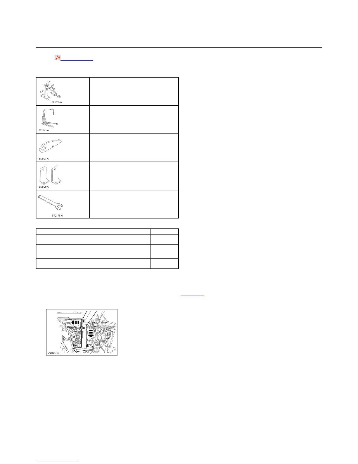
Remove the transmission jack.
SECTION 303-01D: Engine — 6.0L Diesel 2003 F-Super Duty 250-550/Excursion Workshop Manual
Page
1
of 92003 F
-
Super Duty 250
-
550/Excursion Workshop Manual
1/4/2010
http://www.fordtechservice.dealerconnection.com/pubs/content/~WS3O/~MUS~LEN/20/S3
...
INSTALLATION
Procedure revision date: 04/07/2005
Engine
Printable View (1982 KB)
Special Tool(s)
Diesel Engine Lifting Bracket
(D83T-6000-B) 303-D043
Heavy Duty Floor Crane
014-00071
Adapter for 303-D043
303-D043-02
Adapter for 303-D043
303-D043-01
Wrench, Fan Clutch Nut
303-591
Material
SAE 15W-40 Super Duty Motor Oil
XO-15W40-QSD or equivalent
Motorcraft Premium Gold Engine Coolant
VC-7-A (in California, Oregon and New Mexico VC-7-B, in Canada CVC7-A) or equivalent (yellow color)
R-134a Refrigerant
YN-19
Installation
All vehicles
1. With the vehicle in NEUTRAL, position it on a hoist. For additional information, refer to Section 100-02.
2. Raise the engine high enough to clear the No. 1 crossmember, then position the engine into the vehicle.
Vehicles with automatic transmission
3. Align the torque converter studs with the holes in the engine flywheel, then lower the engine onto the engine mount towers.
Vehicles with manual transmission
4. Lower the engine onto the engine mount towers.
All vehicles
5. Remove the Heavy Duty Floor Crane and the Diesel Engine Lifting Bracket.
Vehicles with automatic transmission
Item Specification
WSS-M2C171-
C
WSS-M97B51-
A1
WSH-M17B19-
A
Page 2
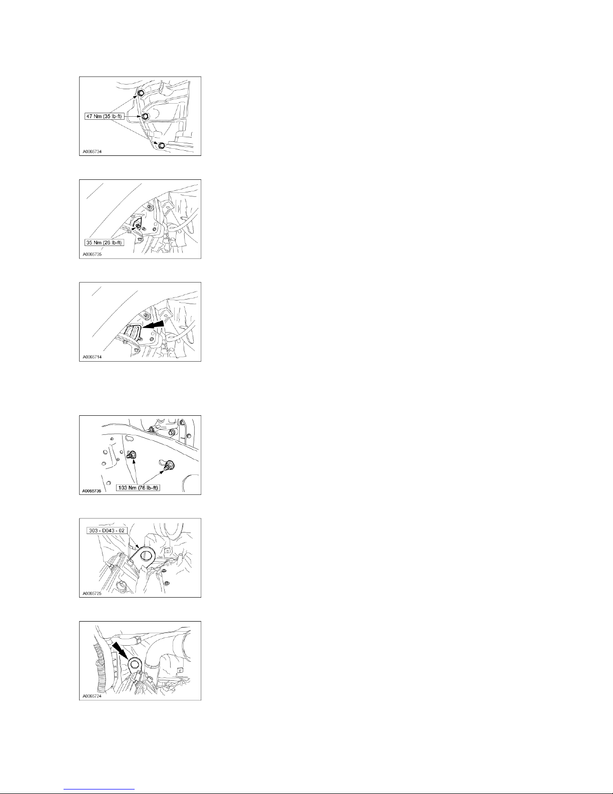
7. Install the transmission-to-engine mounting bolts.
Page
2
of 92003 F
-
Super Duty 250
-
550/Excursion Workshop Manual
1/4/2010
http://www.fordtechservice.dealerconnection.com/pubs/content/~WS3O/~MUS~LEN/20/S3
...
8. Install the new torque converter-to-flywheel retaining nuts.
9. Install the flywheel housing cover.
All vehicles
10. NOTE: LH shown, RH similar.
Install the LH and RH side engine mount retaining nuts.
11. Remove the engine lifting eye from the right side cylinder head.
12. Install the manufacturer's lifting bracket.
13. Remove the two engine lift adapters.
Page 3
Page
3
of 92003 F
-
Super Duty 250
-
550/Excursion Workshop Manual
1/4/2010
http://www.fordtechservice.dealerconnection.com/pubs/content/~WS3O/~MUS~LEN/20/S3
...
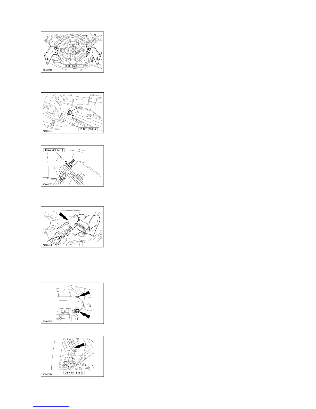
14. NOTE: Position back the starter wiring and block heater harness.
Install the transmission cooler tube bracket and nut.
15. Install the left rear valve cover stud.
16. NOTE: To aid in installation, make sure the turbocharger Marmon clamp stud is positioned towards the drivers side.
Position the turbocharger adapter pipe.
17. NOTE: Left side shown, right side similar.
NOTE: Use a half-moon wrench to aid in accessing the fasteners.
NOTE: Apply anti-seize lubricant to the threads prior to installing the bolts.
Loosely install the bolts for the turbocharger adapter pipe.
18. Install the starter if needed.
Page 4
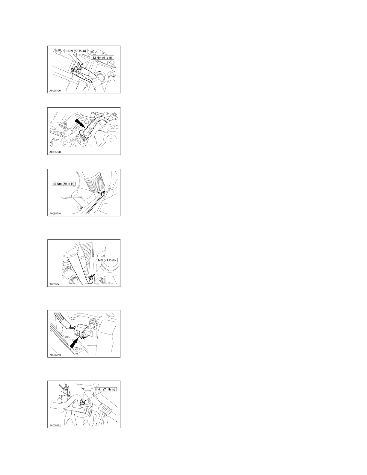
19. Connect the starter wiring and install the solenoid cap.
Page
4
of 92003 F
-
Super Duty 250
-
550/Excursion Workshop Manual
1/4/2010
http://www.fordtechservice.dealerconnection.com/pubs/content/~WS3O/~MUS~LEN/20/S3
...
20. Connect the block heater electrical connector.
21. Connect the ground strap on the right head and install the bolt.
Vehicles with automatic transmission
22. Install the automatic transmission fluid indicator and tube.
All vehicles
23. Position the engine wiring harness back. Connect the crankshaft position (CKP) sensor electrical connector and wiring retainers.
Vehicles with A/C
24. Position the A/C accumulator line and install the nut.
25. Install the A/C compressor.
Page 5
Page
5
of 92003 F
-
Super Duty 250
-
550/Excursion Workshop Manual
1/4/2010
http://www.fordtechservice.dealerconnection.com/pubs/content/~WS3O/~MUS~LEN/20/S3
...
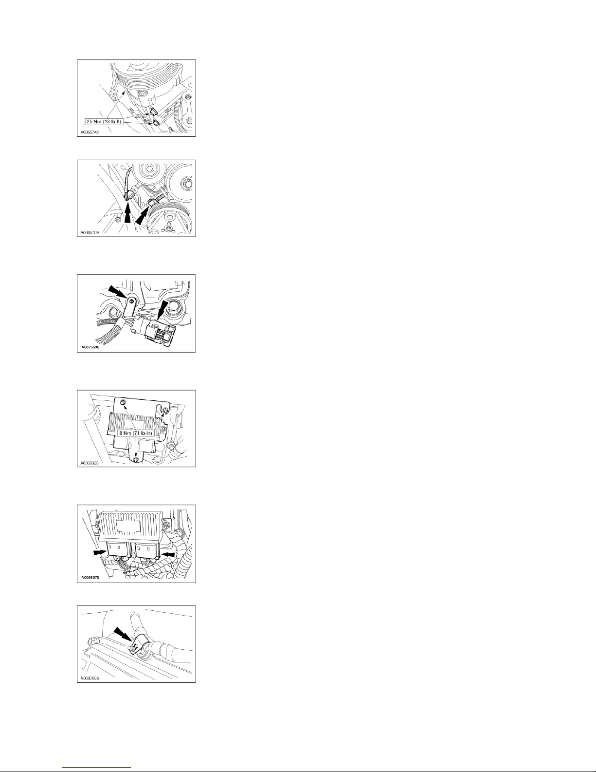
26. Connect the A/C high pressure switch and the clutch electrical connectors.
27. NOTE: Late build shown, early build similar.
Connect the RH glow plug electrical connector.
All vehicles
28. Install the nuts and the glow plug controller.
29. NOTE: Late build shown, early build similar.
Connect the glow plug module electrical connectors.
30. Connect the wiring retainers to the studs.
31. Connect the ground cable and the ground stud.
Page 6
Page
6
of 92003 F
-
Super Duty 250
-
550/Excursion Workshop Manual
1/4/2010
http://www.fordtechservice.dealerconnection.com/pubs/content/~WS3O/~MUS~LEN/20/S3
...
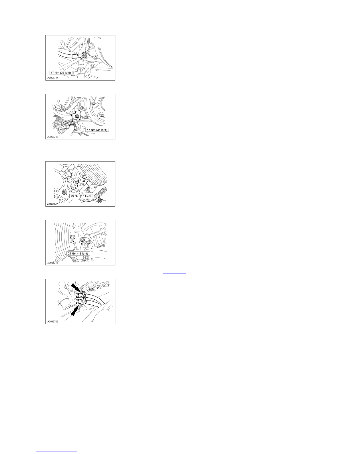
32. Install the battery cable bracket and the nut, and install the RH standoff for the stator.
33. NOTE: The lower bolts need to be installed evenly.
Position the power steering pump and install the lower bolts, and install the LH standoff for the stator.
34. Install the power steering pump upper bolts.
35. Connect the fuel lines and install the clips. For additional information, refer to Section 310-00.
36. NOTE: The intake manifold gaskets can be reused if not damaged.
Install the intake manifold gaskets.
Page 7
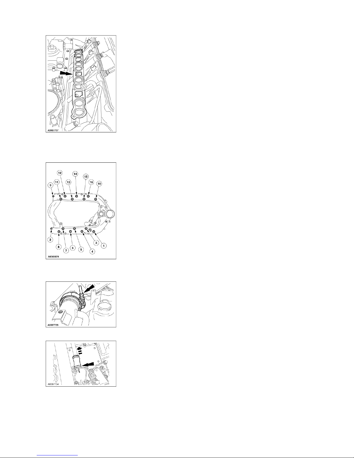
41.
Install the turbocharger heat shield and the nuts.
Page
7
of 92003 F
-
Super Duty 250
-
550/Excursion Workshop Manual
1/4/2010
http://www.fordtechservice.dealerconnection.com/pubs/content/~WS3O/~MUS~LEN/20/S3
...
37. Install the intake manifold and loosely install the bolts.
38. Tighten the bolts in the following sequence.
1. Loosely install the bolts. Tighten bolts to 9-16 to 11 Nm (8 lb-ft).
2. Tighten all bolts to 11 Nm (8 lb-ft) in the sequence shown.
39. NOTE: Do not tighten the clamp at this time.
Install the gasket and loosely install the EGR cooler V-clamp.
40. Slide the EGR cooler hose up and rotate flat to lock.
Page 8
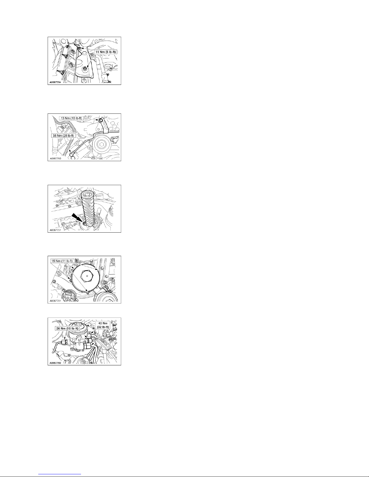
42. Install the fuel line.
46.
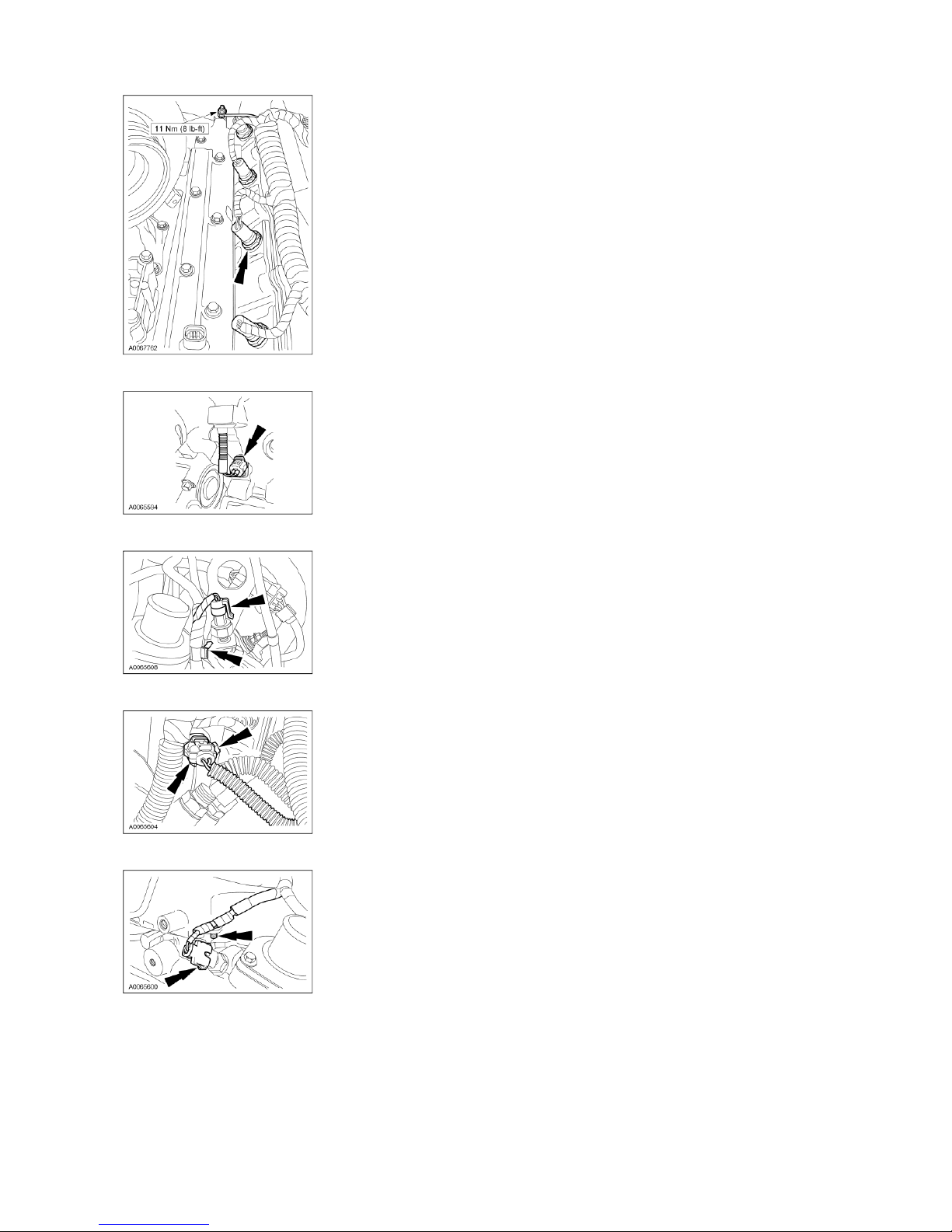
Position the ground wire and install the retaining nut. Connect the eight fuel injector electrical connectors.
Page
8
of 92003 F
-
Super Duty 250
-
550/Excursion Workshop Manual
1/4/2010
http://www.fordtechservice.dealerconnection.com/pubs/content/~WS3O/~MUS~LEN/20/S3
...
Install new sealing washers.
Install the fuel line.
Install the banjo fitting and the bolt.
43. Install the oil filter return tube and bolt.
On new oil filter return tubes, tighten to 6 Nm (53 lb-in).
On used oil filter return tubes, tighten to 3 Nm (27 lb-in).
44. NOTE: Install a new filter.
Install the oil filter and the four bolts.
45. Connect the fuel line fittings.
Page 9
Page
9
of 92003 F
-
Super Duty 250
-
550/Excursion Workshop Manual
1/4/2010
http://www.fordtechservice.dealerconnection.com/pubs/content/~WS3O/~MUS~LEN/20/S3
...
47. Position the engine wiring harness and connect the CMP sensor electrical connector.
48. Connect the retaining clip and exhaust backpressure sensor electrical connector.
49. Connect the wiring retainer and the IAT sensor electrical connector.
50. Connect the water temperature sensor and the pin-type retainer.
 Loading...