

Page 1
Filling station guide
Opening the bonnet. Swivel the Ford badge in the radiator grille upwards. To
unlock the bonnet, insert the key into the lock and turn first anticlockwise. Raise
the bonnet slightly and turn the key fully clockwise. Remove the key immediately
after opening and swivel the Ford badge back.
Opening the fuel filler flap. To unlock turn the key clockwise. Open the flap
fully until it engages. Press the fuel filler cap and, while pressed in, turn it
anticlockwise.
For quick reference when refuelling, you can record below vehicle data
applicable to your own vehicle. The appropriate details can be obtained from
the chapter Capacities and specifications.
Fuel
Fuel tank capacity:
Petrol engine: 55 litres
Diesel engine: 52.7 litres
Use only fuel that meets EN590
specifications. Do not use RME
(bio diesel).
Diesel fuel
Unleaded fuel
(minimum
95 octane)
Unleaded fuel
Engine oil
When adding oil never top up
above the MAX mark.
Viscosity grade
(minimum
91 octane)
07/2004 en RHD
Owner’s Guide
FordFocus
Tyre pressures
When tyres are cold – in bar
(lbf/in2)
Normal loading with
up to 3 persons
Front Rear
FordService
Tyre size
Full loading with more
than 3 persons
Front Rear
FordService
Page 2

The illustrations, technical information, data and descriptions contained in this publication,
were correct at the time of going to print. We reserve the right to make any changes
necessary in line with continuous development and improvement.
This publication may not be duplicated, reprinted, stored in a data processing system or
transmitted by electronic, mechanical, photographic or other means, or recorded, translated,
edited, abridged or expanded without the prior written consent of Ford Motor Company
Limited. The same also applies for parts of this manual and their use in other publications.
Although due care has been taken to make this publication as complete and accurate as
possible, it can still be subject to alterations.
This publication describes options and trim levels available throughout the Ford model range
in every European country, and therefore some of the items covered may not apply to your
vehicle.
Important: Ford genuine parts and accessories have been specifically designed for Ford
vehicles. They are dedicated for your Ford vehicle.
We would like to point out that other parts and accessories than mentioned above have not
been examined and approved by Ford unless explicitly stated by Ford. In spite of continuous
market product monitoring, we cannot certify the suitability of such products. Ford is not
liable for any damage caused by the use of such products.
E Copyright 2004
Issued by Ford-Werke Aktiengesellschaft, Ford Customer Service Organisation
Code No CG3321en RHD 07/2004
Printed by Wyndeham Gait Ltd., Grimsby, North East Lincolnshire, a member of the
Wyndeham Press Group PLC, England.
Page 3

Contents
Before driving
Introduction 2
Instrumentation 4
Controls and features 15
Seating and safety restraints 75
Starting and driving
Starting 95
Driving 98
Roadside emergencies 114
Servicing
Maintenance and care 145
Capacities and specifications 158
Index 179
Page 4

Introduction
PREFACE
Congratulations on acquiring your
new Ford. Please take the time to
get well acquainted with your
vehicle by reading your owner
literature. The more you know and
understand about your vehicle the
greater the safety, economy, and
pleasure you will derive from
driving it.
The Owner’s Guide describes
every option and model variant
available in every European
country and therefore some of
the items covered may not apply
to your particular vehicle.
Furthermore, due to printing
cycles it may describe options
before they are generally
available.
Regular servicing of your vehicle
helps maintain both its roadworthiness and its resale value. A
network of more than 7,000 Ford
Dealers throughout Europe can
help you with their professional
servicing expertise.
Their specially trained personnel
are best qualified to service your
vehicle properly and expertly. Also,
they are supported by a wide range
of highly specialised tools and
equipment specially developed for
servicing Ford vehicles.
Remember to pass on the
Owner’s Guide when
reselling the vehicle. It is an
integral part of the vehicle.
2
Page 5
Introduction
FOR YOUR SAFETY AND
ENVIRONMENT PROTECTION
Warning symbols in
this guide
How can you reduce the risk of
personal injury and prevent
possible damage to others, your
vehicle and its equipment? In this
guide, answers to such questions
are contained in comments
highlighted by the warning triangle
symbol.
Note:
Important information is also given
in paragraphs starting with the
highlighted word Note.
Warning symbols on
your vehicle
When you see this
symbol, it is imperative
that you consult the
relevant section of this
guide before touching or
attempting adjustment of any kind.
RUNNING IN
Avoid driving too briskly during the
first 1,000 miles (1,500 km). Vary
the speed frequently and avoid
labouring the engine. This is
necessary to give the moving parts
a chance to bed in.
New tyres require a running-in
distance of approximately
300 miles (500 km). During this
period, the car may exhibit
different driving characteristics.
Therefore, avoid driving too briskly
during the first 300 miles (500 km).
If possible, you should avoid heavy
use of the brakes for the first
100 miles (150 km) in town and for
the first 1,000 miles (1,500 km) on
motorways.
From 1,000 miles (1,500 km)
onwards you can gradually increase
the performance of your vehicle up
to the permitted maximum speeds.
We wish you safe and pleasurable
driving with your Ford vehicle.
3
Page 6
Instrumentation
4
Page 7
Instrumentation
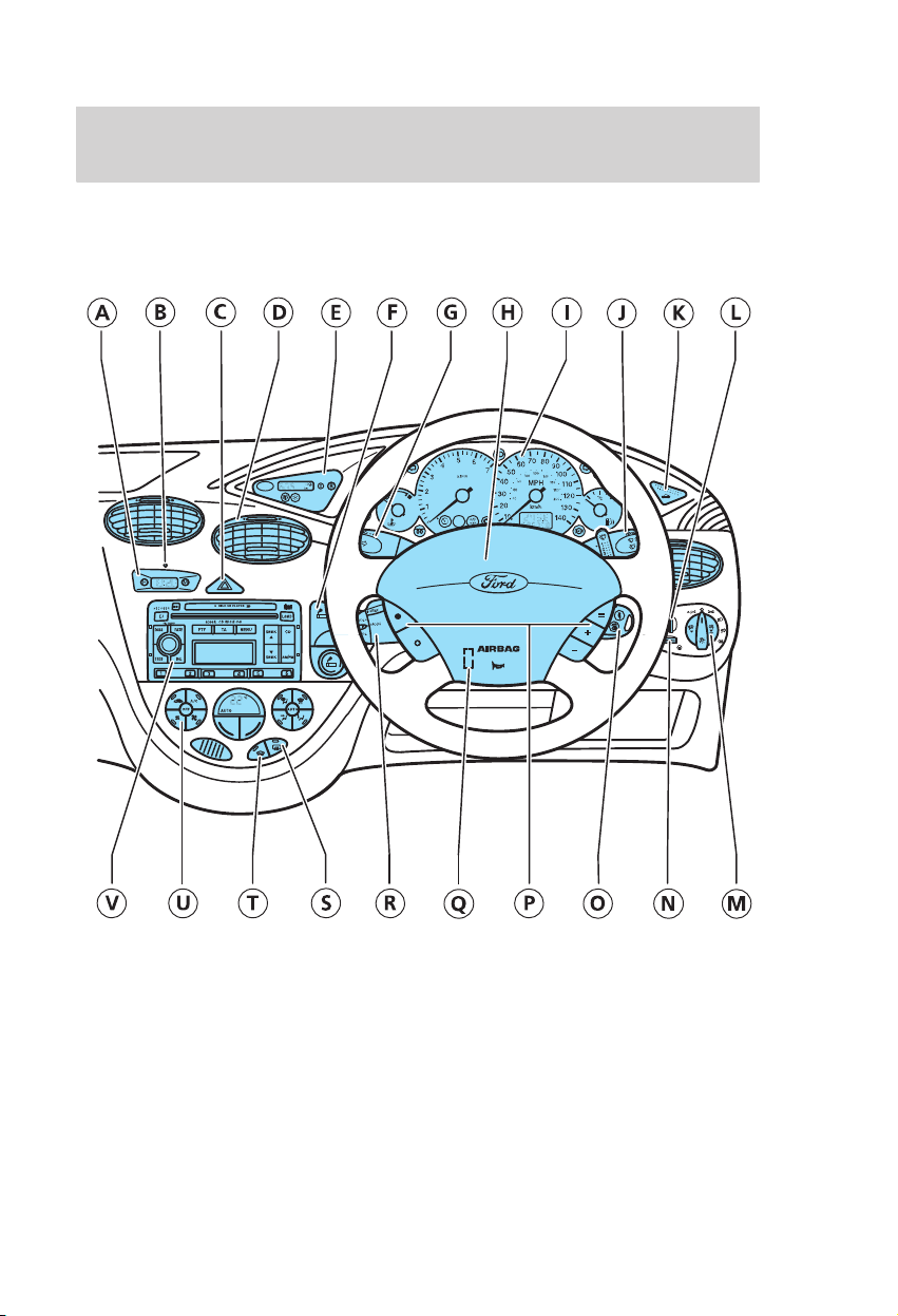
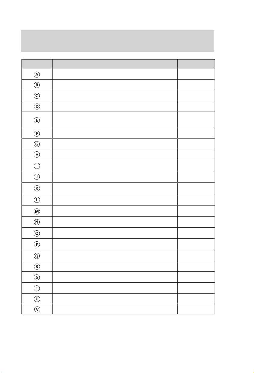
Position Description See page
Digital clock 19
Engine immobilisation system indicator light 70
Hazard flasher 19
Ventilation vents 23
Trip computer/
ST 170 auxiliary instrument cluster
Ashtray/cigar lighter 18
Direction indicators/main beam 32
Horn 32
Instrument cluster 6
Wiper lever 33−34
Luggage compartment release 16
Headlight levelling control 16
Exterior light, front fog lights, rear fog lights 15−16
Instrument lighting dimmer 16
Ignition switch 31
Automatic speed control 36
Steering wheel adjustment 31
Audio remote control 35
Heated rear screen 20
Heated front screen 19
20−22/
13−14
Heating/ventilation/air conditioning 23
Audio equipment: see the separate manual −
5
Page 8
Instrumentation
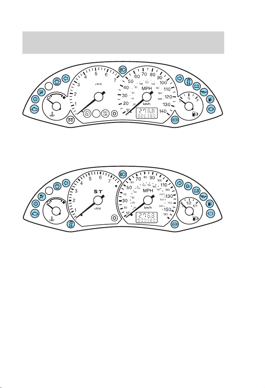
Standard instrument cluster
INSTRUMENT CLUSTER
The individual instruments,
warning and indicator lights are
described on the following pages.
6
ST170
Page 9
Instrumentation
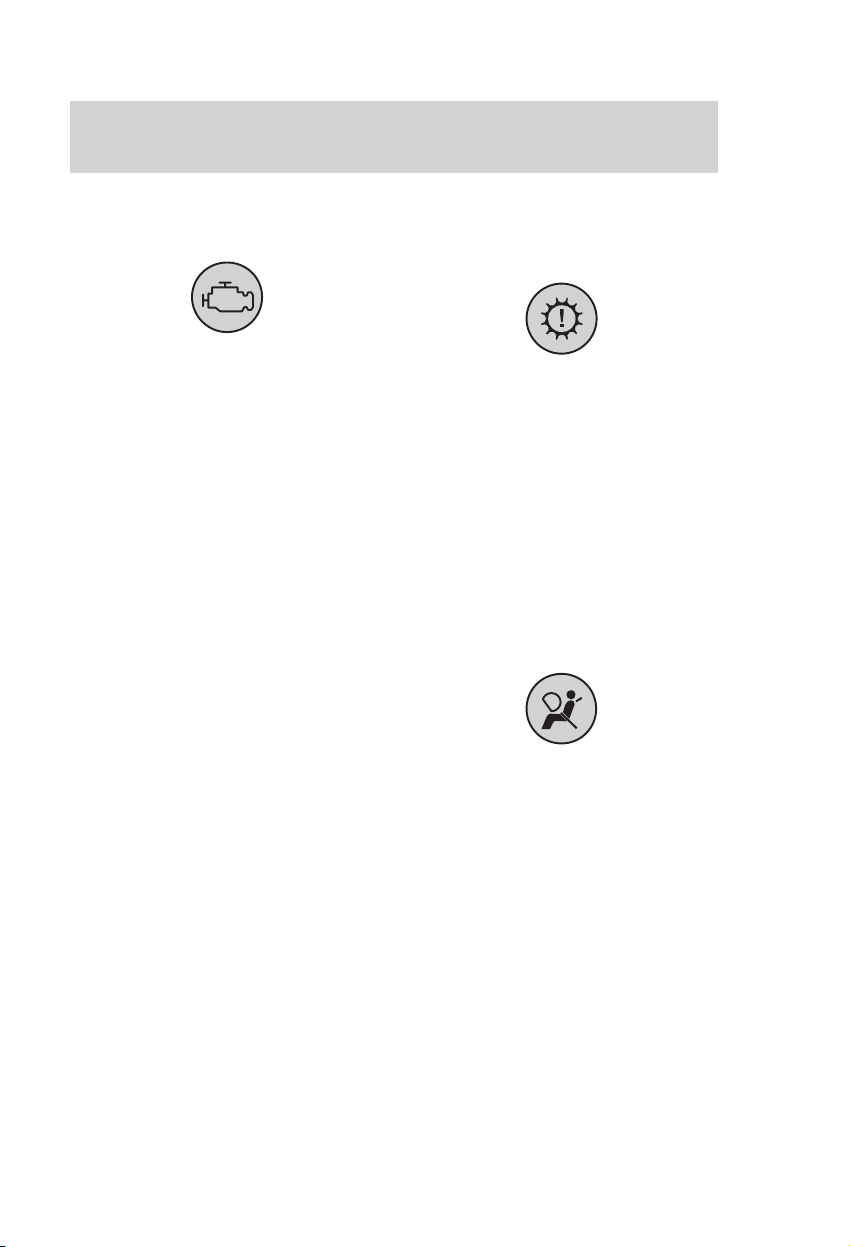
Engine warning light
(depending on country and engine)
Illuminates when the ignition is
switched on. It should extinguish as
soon as the engine starts.
If it illuminates with the engine
running, it indicates a malfunction.
Have this checked by an expert as
soon as possible.
If it flashes when driving, reduce
the vehicle speed immediately.
If it continues to flash, avoid heavy
acceleration and high engine
speeds, and have your vehicle
checked by an expert immediately.
Multi-function warning light:
Automatic transmission/
cooling system
When the ignition is switched on
(position II), the light illuminates
briefly to confirm that the system is
operational.
If it illuminates when driving, it
indicates a malfunction. Have this
checked by an expert.
For further details, refer to the
section Automatic transmission
and Fail safe cooling system.
Air bag/seat belt pretensioner
warning light
When the ignition is switched on
(position II), the light illuminates
briefly to confirm that the system is
operational.
If it illuminates when driving, it
indicates a malfunction. Have this
checked by an expert as soon as
possible.
For further details, refer to the
section Air bag.
7
Page 10
Instrumentation
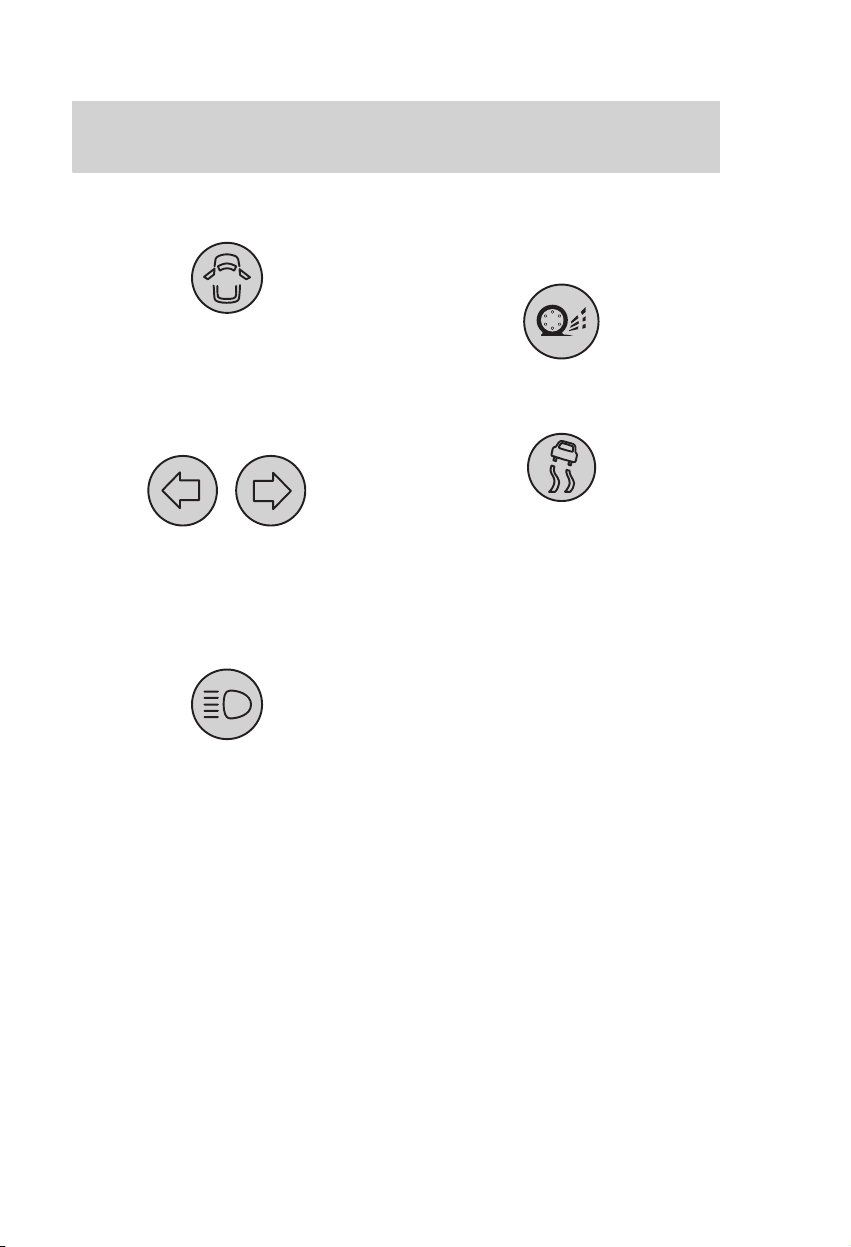
Doors open warning light
Illuminates if any door or the
luggage compartment is not closed
properly.
Direction indicator light
A sudden increase in the rate of
flashing warns of a failed indicator
bulb.
Main beam indicator light
Illuminates when the headlights are
on main beam or when the
headlight flasher is used.
Traction Control System (TCS)/
Electronic Stability Program
(ESP) indicator light
BTCS/TCS indicator light
ESP indicator light
The symbol in the indicator light
depends on the system equipped.
When the ignition is switched on
(position II), the light illuminates
briefly to confirm that the system is
operational.
While driving, the indicator light
flashes during activation of the
system (excluding BTCS).
After switching on the ignition, if
the light does not illuminate or
illuminates continuously while
driving, it indicates a malfunction.
During a malfunction, the system
switches off. Have the system
checked by an expert.
8
Page 11
Instrumentation
Note: If the system is switched off
manually by pressing the Traction
Control System (TCS)/Electronic
Stability Program (ESP) switch,
the indicator light illuminates and
remains on until the system is
either switched back on or the
ignition is switched off.
Note: The Brake Traction Control
System (BTCS) cannot be switched
off.
For further details, refer to the
sections Traction Control System
(TCS)/Electronic Stability
Program (ESP) and Traction
Control System (TCS)/Electronic
Stability Program (ESP) switch.
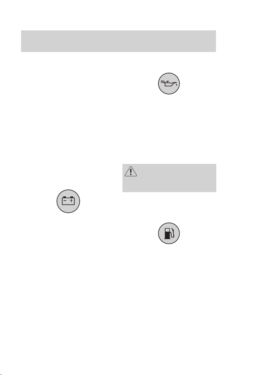
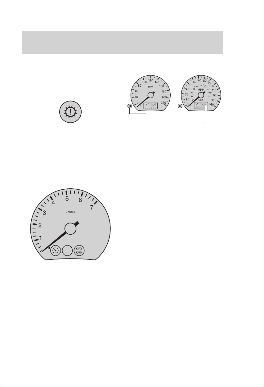
Ignition warning light
Illuminates when the ignition is
switched on. It should extinguish as
soon as the engine starts.
If it does not, or if it illuminates
whilst driving, switch off all
unnecessary electrical equipment
and drive immediately to the
nearest expert.
Oil pressure warning light
Illuminates when the ignition is
switched on. It should extinguish as
soon as the engine starts.
If the light stays on after starting or
illuminates during a journey, stop
immediately, switch off the engine
and check the engine oil level.
Top up straight away if the level is
low.
Do not resume the journey
if the oil level is correct, but
have the engine checked by an
expert.
Low fuel level warning light
(vehicles without a trip computer)
When the warning light illuminates,
refuel as soon as possible.
9
Page 12

Instrumentation
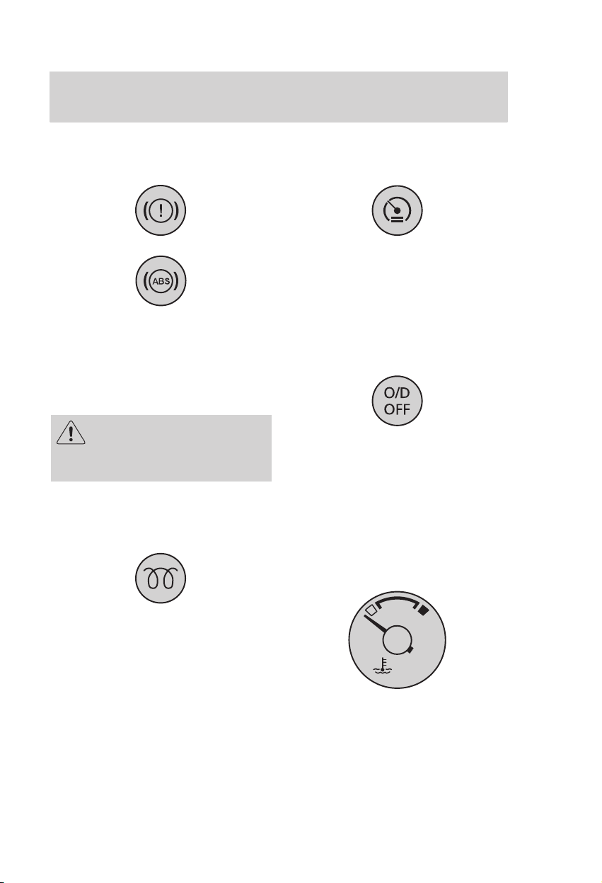
Brake system warning light
When the ignition is switched on
(position II), the light illuminates
briefly to confirm that the system is
operational.
The light remains illuminated when
the handbrake is engaged.
If it illumintes after
releasing the hand brake or
when driving, have the braking
system checked by an expert
immediately.
You will need to press the
brake pedal harder and
make allowance for increased
stopping distances.
ABS warning light
When the ignition is switched on
(position II), the light illuminates
briefly to confirm that the system is
operational.
If it illuminates when driving, it
indicates a malfunction. Have this
checked by an expert.
Normal braking (without ABS) will
be maintained.
Important notes on the use of the
ABS system are to be found in the
section Brakes.
10
Page 13
Instrumentation
Brake system and ABS warning
lights
If both warning lights illuminate at
the same time, stop the vehicle as
soon as it is safe to do so. Have the
braking system checked by an
expert before continuing your
journey.
Reduce vehicle speed
gradually. Use the brake
with great care. Do not step on
the brake pedal abruptly.
Glow plug indicator light
(vehicles with a diesel engine)
Automatic speed control
indicator light
Illuminates when the speed control
system is activated.
For operation details, refer to the
section Automatic speed control.
Overdrive indicator light
(automatic transmission)
Operates in conjunction with
selector lever position D, and
illuminates when the overdrive is
switched off.
For further details, refer to the
section Automatic transmission.
Engine coolant temperature
gauge
Illuminates when the ignition is
switched on. Do not start the
engine until the light extinguishes.
If the light flashes when driving, it
indicates a malfunction. Have this
checked by an expert as soon as
possible.
For further details, refer to the
chapter Starting.
At normal operating temperature,
the needle remains within the
centre section.
11
Page 14
Instrumentation
If the needle enters the red section,
a fail safe cooling system is
activated which allows the vehicle
to be driven temporarily in spite of
depleted engine coolant supply.
Additionally the multi-function
warning light: automatic
transmission/cooling system will
illuminate.
For further details, refer to the
section Fail safe cooling system.
Tachometer
Speedometer
Reset button
Tripmeter/
Odometer
Indicates the current road speed in
mp/h and/or km/h.
Odometer
Registers the total mileage of the
vehicle.
Tripmeter
The tripmeter can register the
mileage of individual journeys. To
reset depress the button.
12
Page 15
Instrumentation
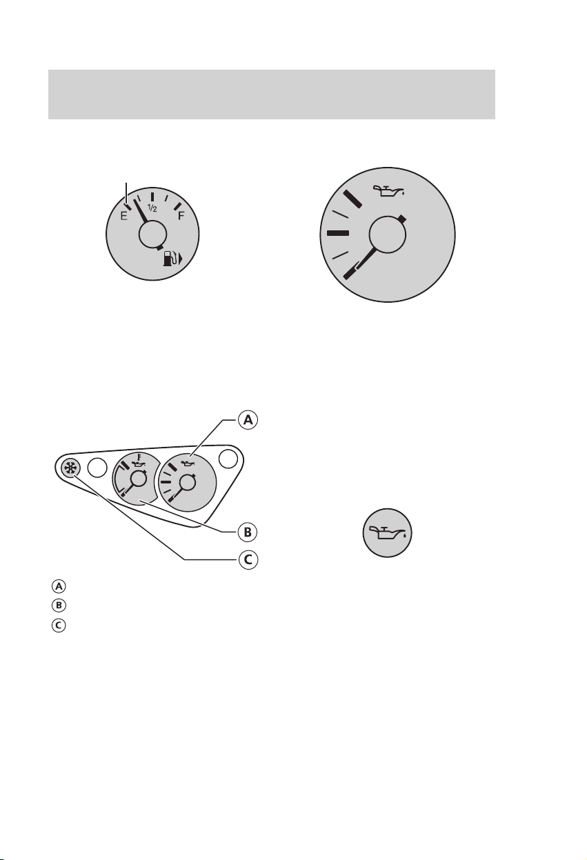
Fuel gauge
Empty
The arrow adjacent to the fuel
pump symbol indicates on which
side of the vehicle the fuel filler cap
is located.
ST170 AUXILIARY INSTRUMENT
CLUSTER
Oil pressure gauge
This gauge indicates engine oil
pressure up to a recommended safe
maximum of 5 bar. During normal
driving the indicated oil pressure
will vary with engine speed, the
pressure rising as engine speed
rises and dropping as engine speed
drops.
Driving with your oil pressure
gauge pointer continuously at the
top of the scale may damage the
engine.
Oil pressure gauge
Oil temperature gauge
Frost warning light
(see page 14)
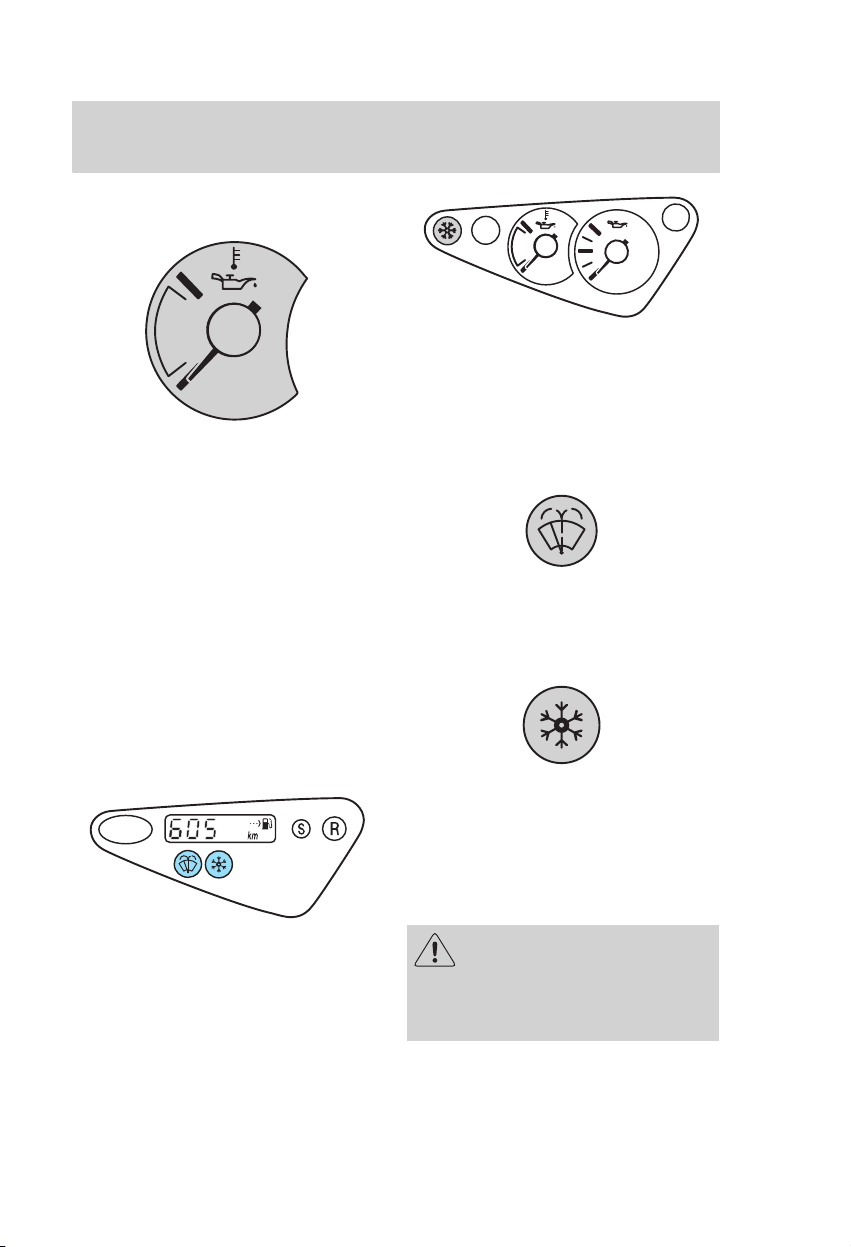
If the engine oil pressure drops
below the normal range, the oil
pressure gauge pointer will drop to
the bottom of the gauge scale and
the engine oil pressure warning
light will illuminate. Stop the
vehicle as soon as safely possible
and switch off the engine
immediately. Check the oil level
and add oil if needed.
For further details, refer to Engine
oil dipstick
13
Page 16
Instrumentation
Oil temperature gauge
Indicates the temperature of the
the engine oil.
At normal operating temperature,
the needle remains within the
normal area. If it enters the red
section, the engine is overheating.
Stop the vehicle as soon as safely
possible, switch off the engine
immediately and let the engine
cool.
This gauge indicates the
temperature of the engine oil, not
the oil level.
ST170 auxiliary instrument cluster
When the ignition is switched on
(position II), these lights illuminate
briefly.
Low washer fluid
Indicates that the washer fluid level
is low. Top up as soon as possible.
Frost warning light
ADDITIONAL WARNING LIGHTS
Trip computer
14
For ambient temperatures below
+5 ºC, the orange sign warns of
possible ice on the roads.
In the ST170, at temperatures
below +1 ºC the warning light glows
red.
Even if the temperature
rises to above +4 ºC there is
no guarantee that the road is free
of hazards caused by inclement
weather.
Page 17
Controls and features
INSTRUMENT PANEL
CONTROLS
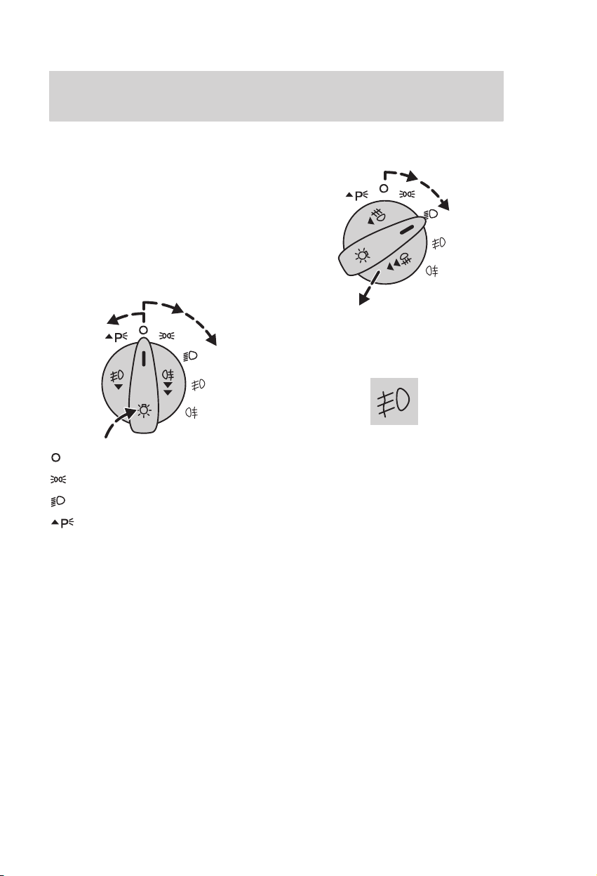
Exterior lights switch
If the exterior lights are switched
on and the ignition is off the
interior lights will illuminate.
Additionally, an audible signal will
be heard if the driver’s door is
opened.
Lights off
Side and tail lights
Headlights
Parking lights
Push in and turn anticlockwise.
Front fog lights
Switch on the exterior lights and
pull out the control switch one
position.
The indicator light will illuminate
when the front fog lights are in use.
The front fog lights should be
used only when visibility is
considerably restricted by fog,
snow or rain.
15
Page 18
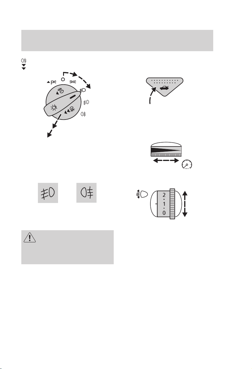
Controls and features
Front and rear fog lights
Switch on the exterior lights and
pull out the control two positions.
On vehicles not equipped with front
fog lights the control switch can be
pulled out only one position.
Both indicator lights will illuminate
when the front and rear fog lights
are switched on.
The rear fog lights may
only be used when visibility
is restricted to less than 50 m and
must not be used when it is
raining or snowing.
Remote luggage compartment
release
To open the luggage compartment,
press the control button.
Instrument lighting dimmer
Headlight levelling control
The level of the headlight beams
can be adjusted according to the
vehicle load.
16
Page 19
Controls and features
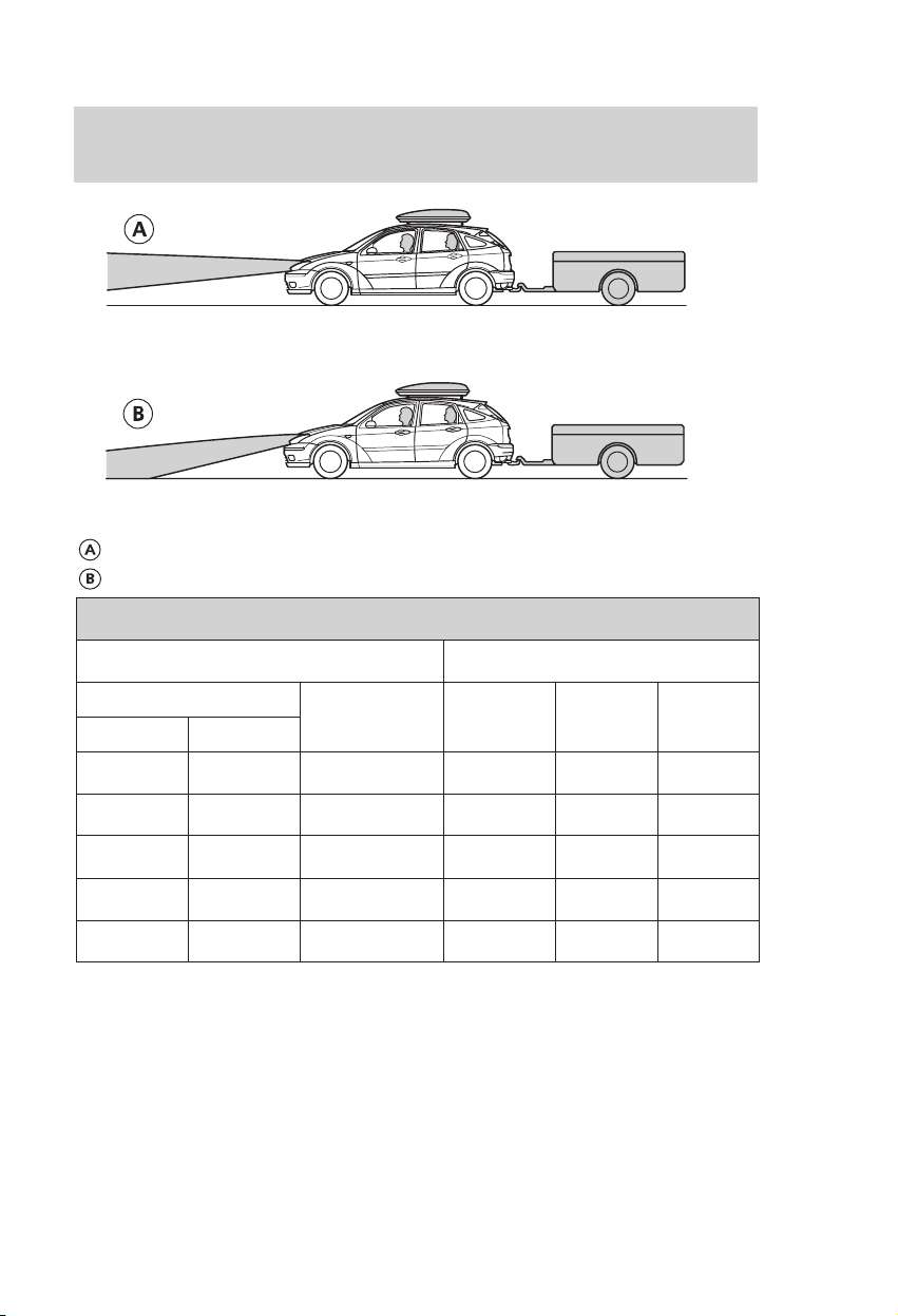
Without headlight levelling system
With headlight levelling system
Recommended headlight levelling control positions
Load Control positions
Persons
Front seats Rear seats
Load in
luggage
compartment
3-/5-door 4-door Estate
1
1 – – 0 0 0
2 – – 0 0 0
2 3 – 1.0 1.0 1.0
2 3 max.
1 – max.
1 Vehicle weights can be found in the chapter
Capacities and specifications.
1
1
1.5 1.5 1.5
2.5 2.5 2.5
Higher switch positions (+1) may be necessary
when towing a trailer.
17
Page 20
Controls and features
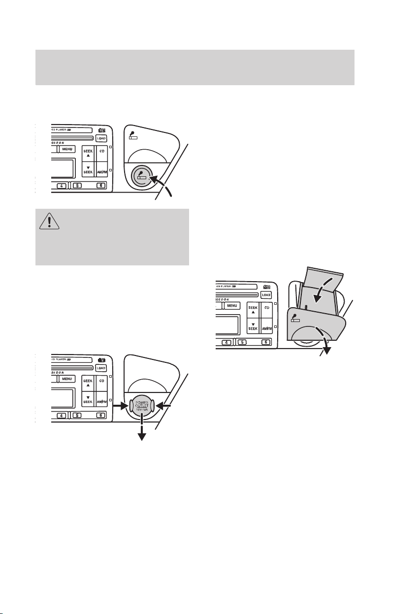
Cigar lighter
Never hold the lighter in, as
this will result in damage.
Always remove the lighter as a
precaution when children are left
alone in the vehicle.
To use the lighter press it in and
wait until it pops out automatically.
The lighter will also operate when
the ignition is switched off.
Power point
The lighter socket and power point
can be used to power 12 volt
appliances having a maximum
current rating of 10 amperes.
However, if the engine is not
running, this will cause the battery
to discharge. On vehicles without a
cigar lighter press in both sides of
the cover on the socket and remove
it.
When connecting appliances, use
only specified connectors from the
Ford Accessory range.
Front ashtray
Pull to open.
To empty, push down the cover and
remove the ashtray.
18
Page 21
Controls and features
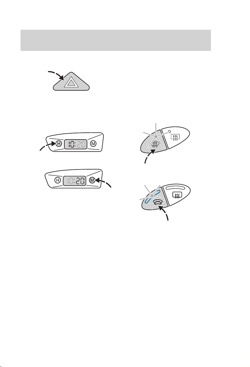
Hazard flasher switch
Press the switch to turn on or off.
The hazard lights can be operated
when the ignition is off.
Digital clock
Switch on the ignition first.
To set the time, use the H (hour)
and M (minute) buttons. Each
press increments the number by
one. For rapid setting, hold the
appropriate button until the
required number is reached.
To toggle between 12 or 24 hour
format, depress both buttons
simultaneously and then release
them.
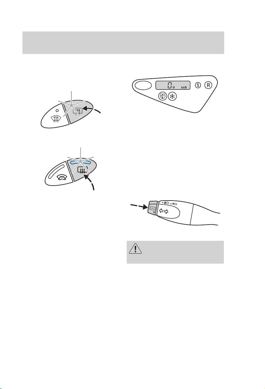
Heated front and rear screen
Use for quick defrosting or
demisting of the front or rear
screen. It should be switched on
only if necessary.
Heated front screen switch
Vehicles with manual
air conditioning
Vehicles with Electronic
Automatic Temperature Control
The system operates only when the
engine is running. Press the switch
to turn on or off.
The heating system switches off
automatically after a short period of
time.
19
Page 22
Controls and features
Heated rear screen switch
Vehicles with manual
air conditioning
Vehicles with Electronic
Automatic Temperature Control
Switch on the ignition first.
Electrically operated door mirrors
also have a heating element to clear
the glass. This system operates
when the heated rear screen is
switched on.
The heating system switches off
automatically after a short period of
time.
TRIP COMPUTER
The following functions are
available when the ignition is on:
• Outside temperature
• Average speed
• Instantaneous fuel consumption
• Average fuel consumption
• Remaining fuel range
Controls
Info−button
Press to change between functions.
For road safety reasons, set
and reset the functions only
when the vehicle is stationary.
20
Page 23
Controls and features
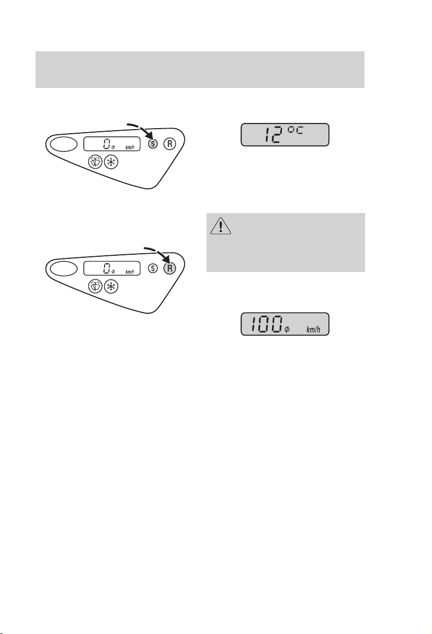
Select button
Press to toggle between metric and
imperial units.
Reset button
Press to reset the function (if
resettable).
Outside temperature
Shows the outside air temperature.
A short audible warning will sound
in the following conditions:
+4 ºC or lower: frost warning
0 ºC or lower: danger of icy roads.
Even if the temperature
rises to above +4 ºC there is
no guarantee that the road is free
of hazards caused by inclement
weather.
Average speed
Indicates the average speed
calculated over the last 600 miles
(1,000 km) or since last reset.
Press the reset button to set to
zero.
21
Page 24
Controls and features
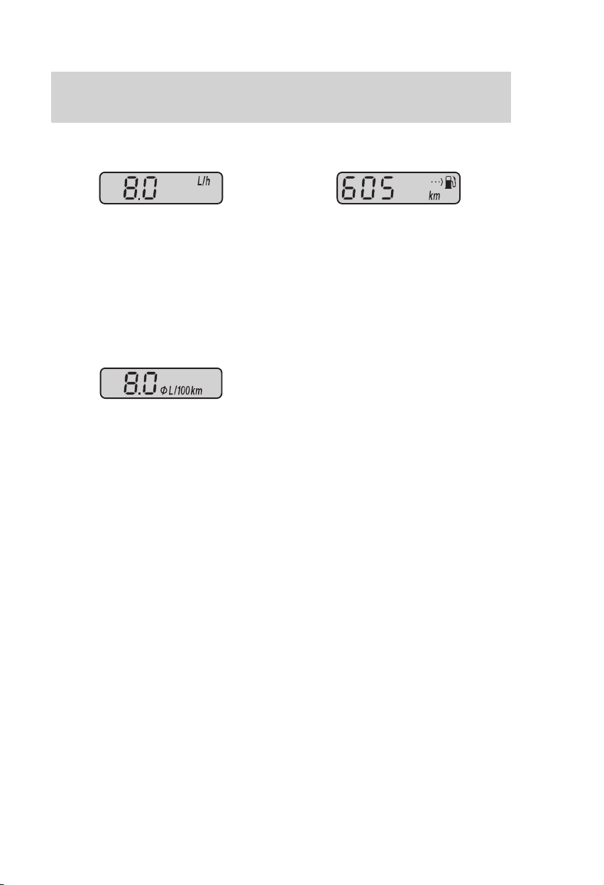
Instantaneous fuel consumption
Indicates the current fuel
consumption. Frequent sampling
enables the computer to react
instantaneously to changes in
driving conditions but may cause
large display value fluctuations in
some circumstances.
Average fuel consumption
Indicates the average fuel
consumption after the function was
last reset.
Press the reset button at any time
to reset the average fuel
consumption.
Remaining fuel range
Indicates the approximate distance
the vehicle will travel on the fuel
remaining in the tank. Changes in
driving pattern may cause the value
to vary.
A short audible warning will sound
at the following ranges: 50 miles
(80 km), 25 miles (40 km),
12 miles (20 km), 0 miles (0 km)
22
Page 25
Controls and features
HEATING, VENTILATION AND
AIR CONDITIONING
Outside air
Always keep the air intakes forward
of the front screen free of snow,
leaves etc., to allow the system to
function effectively.
Recirculated air
When recirculated air is selected,
only the air currently in the
passenger compartment will be
circulated. Outside air will not
enter the vehicle.
Note: It is not recommended to
use recirculated air for more than
30 minutes as there is no air
exchange and the windows may
mist up.
Fresh air filter/active carbon
filter
The fresh air filter removes most
potentially harmful particles such
as pollen, industrial fallout and road
dust from entering the vehicle’s
interior. The active carbon filter
removes odeurs.
In an automatic car wash, you
should switch off the ventilation
blower to prevent the filter
collecting wax deposits.
Blower
The blower motor may emit noises.
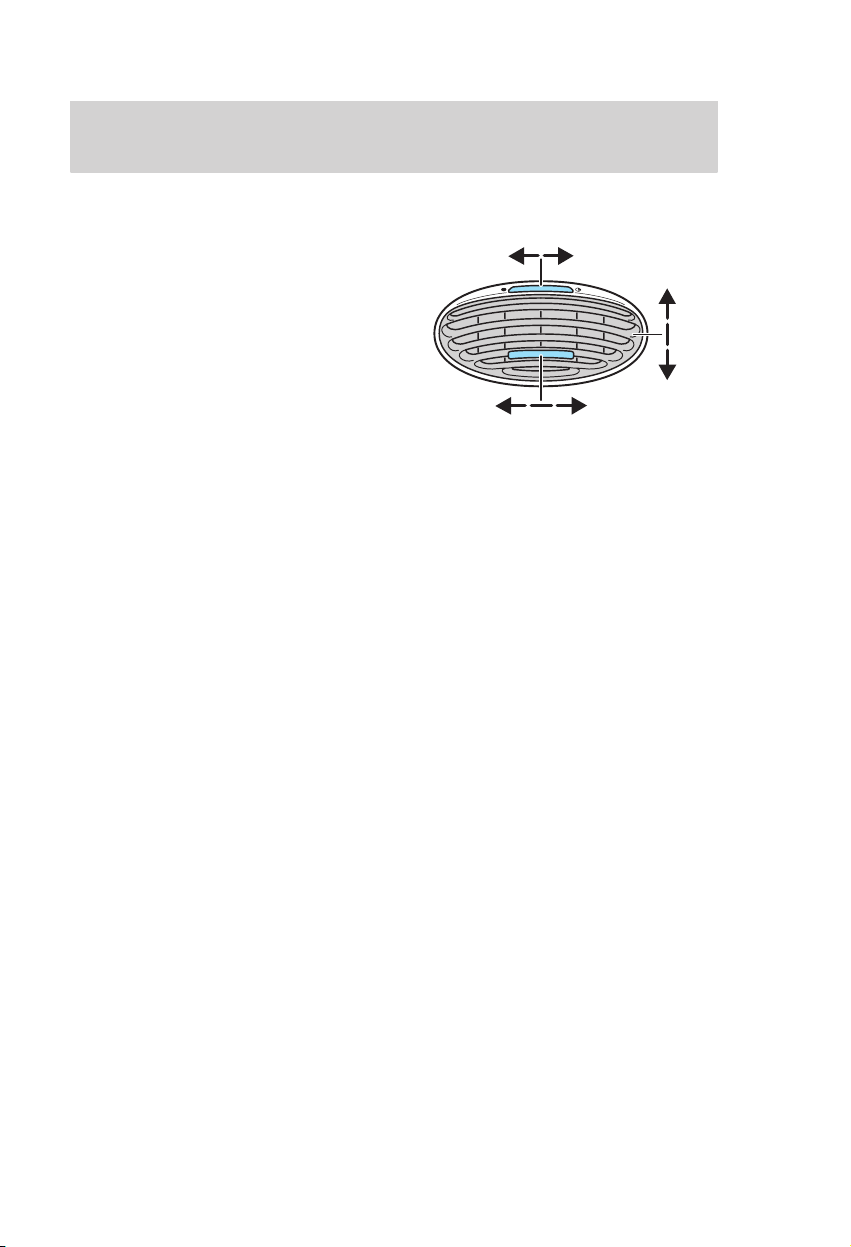
Ventilation vents
Closed Open
Left Right
Heating
The heating depends upon the
coolant temperature and is
therefore only effective when the
engine is warm.
Air conditioning
The air is directed through the
coolant heat exchanger where it is
cooled if the air conditioning is
switched on. In addition, humidity
is extracted from the air to help
keep the windows free of mist.
The resulting condensation is
directed to the outside of the
vehicle. It is therefore quite normal
if you notice a small pool of water
underneath the parked vehicle.
Note: The air conditioning system
only operates when the
temperature is above +4 ºC, the
engine is running and the blower is
switched on. Operating the air
conditioning leads to higher fuel
consumption.
Up
Down
23
Page 26
Controls and features
General notes on controlling
the climate in the vehicle’s
interior
Close all the windows completely.
To warm the interior effectively,
direct the heated air to the footwell
area. In cold or humid weather,
direct some of the air towards the
front screen and side windows.
To cool the interior effectively,
direct the cooled air towards the
face level.
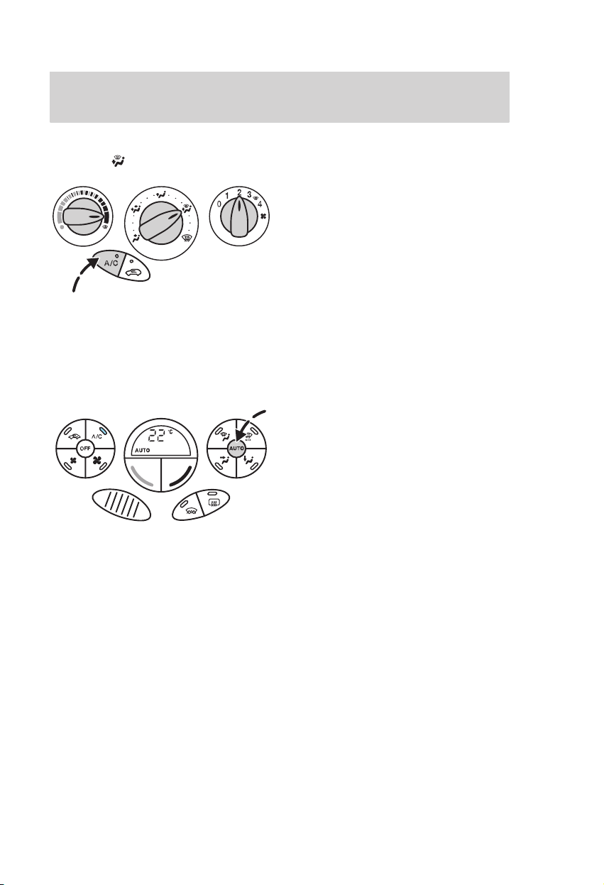
CONTROLS
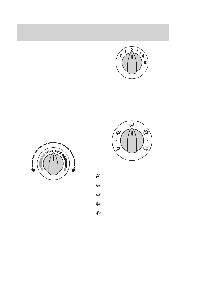
Adjusting the temperature
Temperature
To increase the blower speed,
select a higher number.
With the blower turned off, the
front screen may mist up.
Air distribution control
Directs the air flow as follows:
Cold
Adjust as necessary.
Note: The heating effect depends
upon the coolant temperature and
is therefore only effective when the
engine is warm.
Blower
The blower is off in the 0 position.
24
Warm
Face level
Face level/footwell
Footwell
Footwell/front screen
Front screen
The air distribution control can be
set to any position between the
symbols.
Page 27
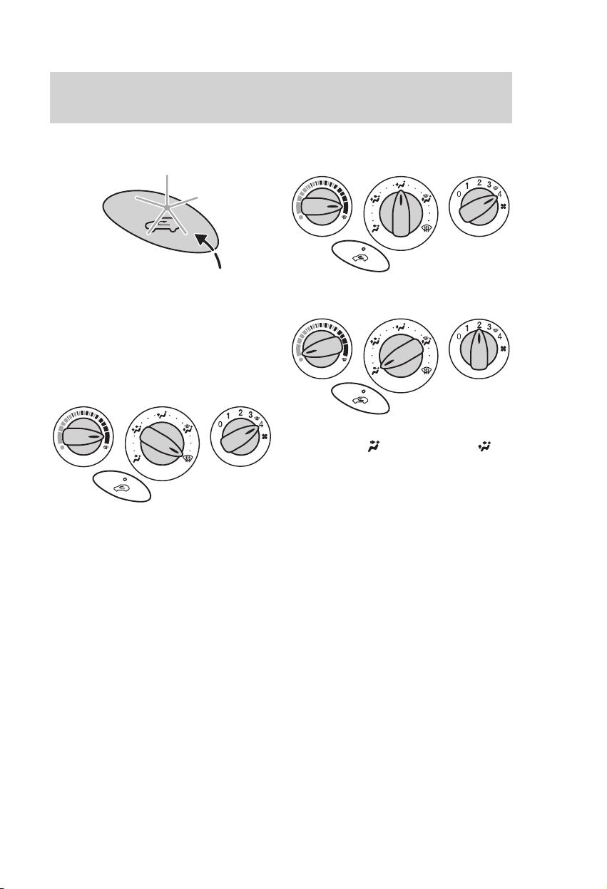
Controls and features
Recirculated air
Press the button to toggle between
outside air and recirculated interior
air.
Front screen defrosting/
demisting
The recirculation funciton is
switched off automatically. If
necessary turn the heated rear and
front screens on.
Rapid heating of vehicle interior
Ventilation
Set the air distribution control to
the position
Set the blower to any position.
Open the centre and side vents to
suit individual requirements.
or the position .
25
Page 28
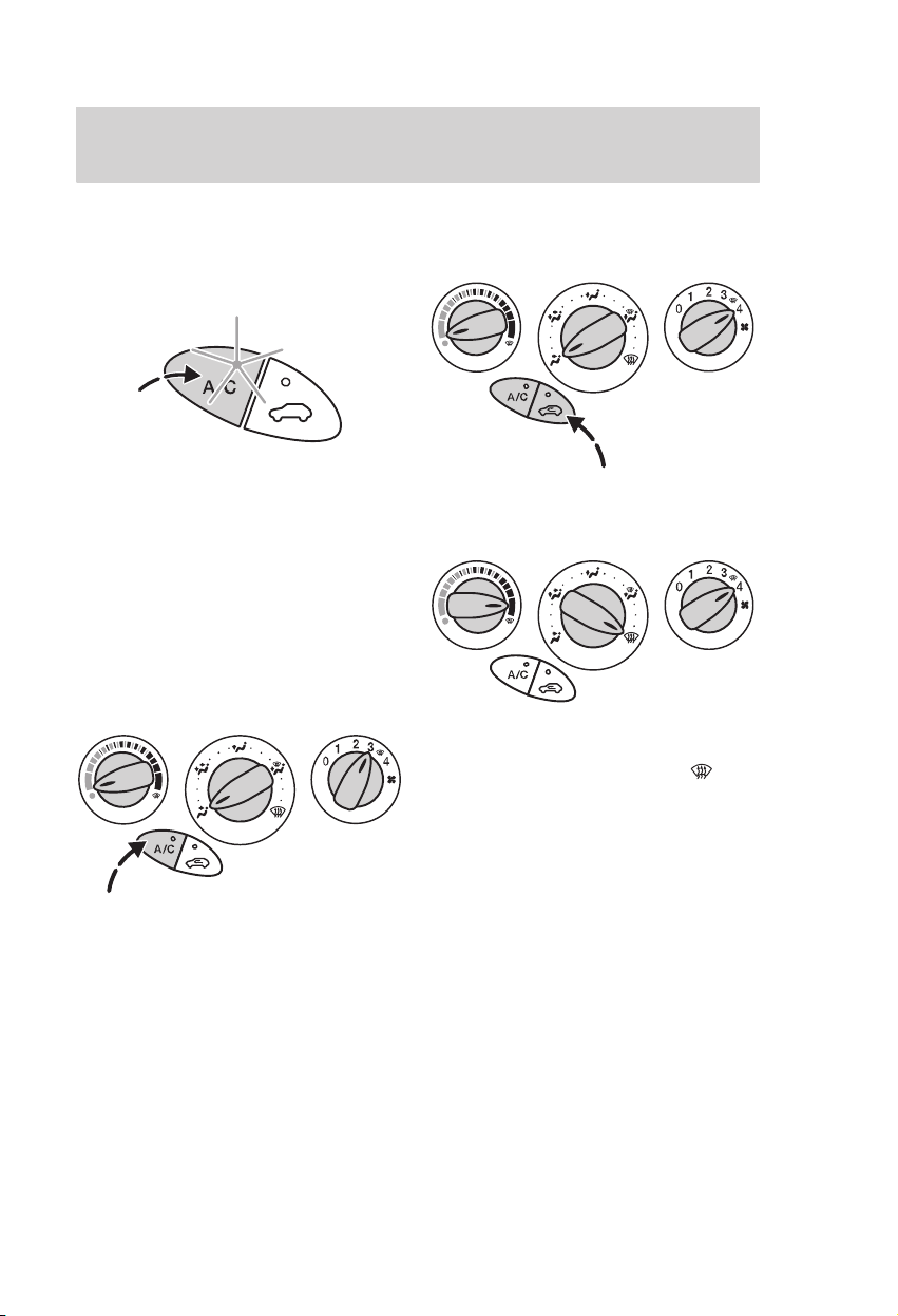
Controls and features
MANUAL AIR CONDITIONING
Switching the air conditioning
on and off
To switch the cooling effect on and
off, press the A/C switch. The light
in the switch indicates operation.
If the blower is turned to position
0, the air conditioning will turn off.
When the blower is turned on
again, the air conditioning will
reactivate automatically.
Cooling with outside air
Rapid cooling of the vehicle
interior
Front screen
defrosting/demisting
Outside air will flow into the
vehicle. As long as the air
distribution control is set to ,
recirculated air cannot be selected
and the air conditioning will be
turned on automatically. In this
particular case, the A/C light in the
switch will not illuminate. Make
sure the blower is on.
26
Page 29
Controls and features
Reducing air humidity in
position
The air conditioning extracts
humidity from the air and the
windows are demisted faster.
ELECTRONIC AUTOMATIC
TEMPERATURE CONTROL
The temperature, amount and
distribution of the air flow are
controlled automatically and
adjusted according to the driving
and weather conditions. Pressing
the AUTO button once switches on
the AUTO mode.
The recommended system settings
for all seasons are 22 ºC and AUTO
mode (the air conditioning is
switched on).
The individual settings can be
adjusted as necessary.
Avoid adjusting the settings when
the vehicle interior is extremely hot
or cold. The Electronic Automatic
Temperature Control adjusts to the
current circumstances
automatically.
For the system to function
properly, the side and centre vents
should be fully open.
The sensor which measures the
interior temperature is located
below the temperature and blower
controls and should not be covered
by any objects.
At low outside temperatures, when
the system is in AUTO mode, the
air stream will be directed to the
front screen and the side windows
as long as the engine is cold.
27
Page 30
Controls and features
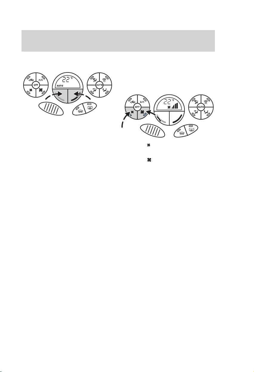
Adjusting the temperature
Blue button: lower temperature.
Red button: higher temperature.
The recommended standard setting
is 22 ºC.
The individual temperature can be
set between 16 ºC and 28 ºC using
the buttons. In position LO (below
16 ºC) the system will switch to
permanent cooling, in HI (above
28 ºC) to permanent heating, and
not regulate a stable temperature.
Manual operation of the
Electronic Automatic
Temperature Control
Blower
Press the button to reduce
blower speed.
Press the button to increase
blower speed.
The blower setting is indicated in
the display.
28
Page 31

Controls and features
Air distribution
To adjust air distribution, press the
desired button. The light in the
button indicates operation. Any
combination of settings
can be selected simultaneously.
Face level
Footwell
Front screen
When is selected, , and
switch off automatically and the air
conditioning switches on. Outside
air will flow into the vehicle.
Recirculated air cannot be selected.
, and
Front screen defrosting/
demisting
Set the air distribution control to
. Outside air will flow into the
vehicle. Air conditioning is
automatically selected. As long as
the air distribution is set to ,
recirculated air cannot be selected.
The blower speed and the
temperature control operate
automatically and cannot be
adjusted manually. The blower is
set to maximum and the
temperature to HI.
When is selected, the heated
front and rear screens switch on
automatically.
To return to AUTO mode, press
AUTO or the button(s) with
illuminated indicator lights.
29
Page 32
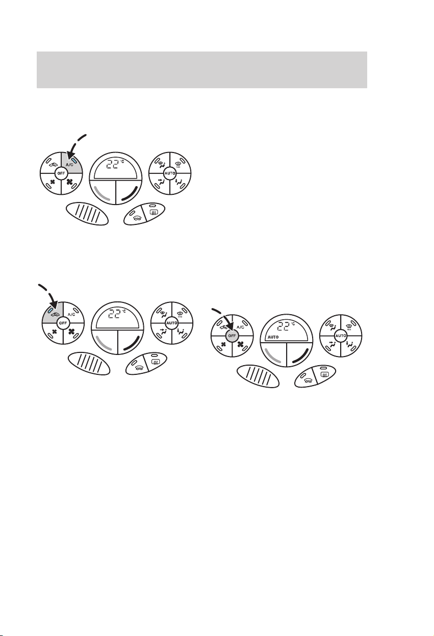
Controls and features
Switching the air conditioning
on and off
Press the A/C button to switch the
air conditioning on/off.
Recirculated air
Press the recirculated air control to
toggle between outside air and
recirculated air.
Automatic recirculated air
control
When the system is in AUTO mode
and the interior and exterior
temperatures are quite hot, the
climate control system
automatically selects the
recirculated air position to
maximise cooling of the interior.
Once the selected temperature is
reached, the system will
automatically change to the outside
air position. The indicator light in
the button does not illuminate
during the automatic operation.
To switch off the Electronic
Automatic Temperature Control
Press OFF to switch off the
Electronic Automatic Temperature
Control.
If the recirculated air button is also
pressed, no outside air will enter
the vehicle.
Press any button (apart from the
recirculated air, heated front and
rear screen buttons) to switch the
Electronic Automatic Temperature
Control back on.
30
Page 33

Controls and features
STEERING COLUMN
CONTROLS
Steering column lock/
ignition switch
0 Ignition off
When the key is removed from the
ignition switch the steering column
lock will be activated and prevent
the steering wheel from being
turned.
On vehicles with automatic
transmission, the ignition key can
be returned to position 0 only if the
selector lever is in the park
position P.
I Steering unlocked. Ignition and
all main electrical circuits are
disabled.
The ignition should not be left in
this position for too long to avoid
discharging the battery.
II Ignition switched on, all
electrical circuits operational.
Warning and control lights
illuminate. This is the key position
when driving and must also be
selected when being towed.
III Starter motor activated. Release
the key as soon as the engine
starts.
Adjusting the steering wheel
Never adjust the steering
wheel when the vehicle is
moving.
Release the locking lever to adjust
the height of the steering wheel
and its distance from the driver.
Return the lever to its original
position to secure the wheel.
For further details on sitting in the
correct position, refer to the
section Seats.
Never return the key to the
0 position when the vehicle
is in motion.
31
Page 34

Controls and features
Horn
The horn can also be operated
when the ignition is off.
Multi-function switch
The following functions will operate
only with the ignition switched on.
Direction indicator
Briefly tap the lever up or down
and the direction indicator will
flash three times.
Main/dipped beam
When the headlights are switched
on, pull the lever towards the
steering wheel to toggle between
main and dipped beam.
Headlight flasher
Pull the lever slightly towards the
steering wheel.
Info button
32
For operation details, refer to the
section Trip computer.
Page 35

Controls and features
Wiper lever
The following functions will operate
only with the ignition switched on.
Front screen
• Lever positions:
Single wipe
Intermittent wiping
Rear screen
• Intermittent wiping
Pull the lever towards the steering
wheel.
• Reverse gear wiping
If no normal rear wiper function is
selected, but the front wipers are
set to intermittent, normal or high
speed operation, when reverse gear
is selected, the rear wiper will
follow the front wiper interval (at
intermittent or normal speed).
Intermittent wipe interval rotary
switch:
1 = Short time interval
6 = Extended time interval
Normal wiping
High speed wiping
33
Page 36

Controls and features
Washer
While the button at the end of the
lever is pressed or the lever is
pulled towards the steering wheel
the washer will work in conjunction
with the wipers.
Once the wash/wipe cycle is
completed, the wipers will pause
and then perform one more wipe to
clear the screen.
This will also operate the headlight
washers when the headlights are
switched on (depending on country
and equipment fitted).
After releasing the button or lever,
the wipers operate for a short time.
Do not operate the washer
for more than 10 seconds at
a time, and never when the
reservoir is empty.
34
Page 37

Controls and features
Audio remote control
Select radio, CD or cassette mode
on the radio.
The following functions can be
operated with the remote control.
Volume
Volume up: Pull the VOL + switch
towards the steering wheel.
Volume down: Pull the VOL −
switch towards the steering wheel.
Seek
• In CD mode, it will select the
next or previous track.
ModeD
Briefly press the " button on the
side:
• In radio mode, this will locate
the next pre-set radio station.
• In CD mode, this will select the
next CD if a CD changer is fitted.
The CD changer is installed under
the passenger’s seat.
• In all modes to abort a traffic
message during broadcasting.
Press and hold the " button on the
side:
• In radio mode, to change the
waveband.
Move the SEEK switch towards the
steering wheel or the instrument
panel:
• In radio mode, this will locate
the next radio station up or down
the frequency band.
35
Page 38

Controls and features
Automatic speed control
The automatic speed control
system should not be used
in heavy traffic, on twisty roads or
when the road surface is slippery.
The indicator light in the
instrument panel will illuminate.
To switch on
The system is ready to store a
speed.
To store a speed
Press the or – switch. The
automatic speed control will
maintain the vehicle at the current
speed.
The system will not function until
the vehicle is travelling at speeds
above 28 mph (45 km/h).
To change speed
Press the switch to accelerate.
Press the – switch to decelerate.
The vehicle speed will change
without the need to depress the
accelerator pedal.
The set speed becomes the new
stored speed.
The vehicle speed can be changed
slightly by momentarily pressing
the appropriate button.
To cancel or resume
To cancel, depress the brake or
clutch pedal, or press the switch.
The indicator light in the cluster
will extinguish.
Press the switch to resume
automatic speed control at the last
stored speed setting.
36
Page 39

Controls and features
To switch off
The stored speed will be erased.
The indicator light extinguishes.
OVERHEAD CONTROLS
Interior lights
Door
Off On
activated
On some models, with the switch in
the ‘door activated’ position, the
interior lights will stay on for a
while after the doors are shut. They
go off immediately after the ignition
is turned on.
When parking your vehicle with the
doors open for a long period of
time, the interior lights are
switched off automatically after
30 minutes.
To switch the lights back on switch
on the ignition (position II) for a
short time.
Reading lights
Standard
Door
activated
Off On
ST-170 (Optional)
Standard
ST170 (Optional)
37
Page 40

Controls and features
Interior rear view mirror
To reduce glare when driving at
night dip the mirror by adjusting
the lever.
Sun visors
The sun visors can be released from
the retention clips and swivelled
towards the side window.
The mirror cover can be slid to the
left and right.
Vanity mirror lights
On.
Off.
Sunroof
The power sunroof can be operated
when the ignition is switched on.
Note: The sunroof can also be
operated when the ignition is off via
the global opening/global closing
function. Refer to the section
Global opening/global closing.
Before operating the power
sunroof you should verify it
is free of obstructions and ensure
that children and/or pets are not
in the proximity of the sunroof
opening. Failure to do so could
result in serious personal injury.
It is the primary responsibility of
the supervising adults to never
leave a child unattended in a
vehicle and to never leave the
keys in an unattended vehicle.
38
Page 41

The sunroof is operated by a switch
located between the sun visors.
Note: When the sunroof is
operated often during a short
period of time, the system might
become inoperable for a certain
time to prevent damage due to
overheating.
There are two ways of opening the
sunroof – the rear of the sunroof
lifts open or the sunroof opens from
the front, sliding back under the
roof. In order to change from one
opening mode to the other, you
have to close the sunroof first. The
sunroof opens/closes when the
switch is pressed.
Note: You may hear a buffeting
noise at low speeds with the
sunroof fully open. To reduce this
noise, close the sunroof by
approximately 5 cm or lower any of
the side windows by a small
amount.
Controls and features
To open and close the sunroof
To open the closed sunroof, press
. The sunroof slides back under
the roof.
To close, press
To tilt the rear of the closed
sunroof, press .
To close, press .
To open/close the sunroof
automatically
Briefly press either side of the
switch to the second action point.
Press again to stop. If the closed
position is reached, the sunroof
stops automatically. Movement can
be interrupted by pressing the
switch in any direction.
.
39
Page 42

Controls and features
Anti-trap function sunroof
The sunroof will stop automatically
while closing and reverse some
distance if there is an obstacle in
the way.
To override this protection function
when there is a resistance, e.g. in
the winter, proceed as follows:
Careless closing of the
sunroof can override the
protection function and cause
injuries.
• Close the sunroof twice until it
reaches the resistance and let it
reverse.
• Close the sunroof a third time to
the resistance. Briefly release the
switch and press again immediately.
The sunroof will override the
resistance and can then be closed
fully.
While the sunroof is being
closed for the third time,
the anti−trap function is disabled.
Make sure there are no obstacles
in the way of the closing sunroof.
Relearning function
In case the sunroof does not close
properly anymore, follow this
relearning procedure:
• Raise the rear of the sunroof as
far as possible. Release the switch.
• Press and hold the same switch
again for 30 seconds until you see
the sunroof move.
• Release the switch and
immediately press and hold it
again. The sunroof will close, open
fully and then close again. Do not
release the switch before the
sunroof has reached the closed
position for the second time.
40
Page 43

Controls and features
If the switch is not pressed
continuously, the relearning
function will be interrupted. Start
the procedure once more from the
beginning.
The anti-trap function is
not active during this
procedure. Make sure that there
are no obstacles in the way of the
closing sunroof.
Safety mode
If the system detects a malfunction,
it enters a safety mode. The
sunroof will move for only about
0.5 seconds at a time and then stop
again. Close the sunroof by
pressing the switch again when the
sunroof stops moving. When the
rear of the sunroof is lifted, lift the
rear all the way and then close the
sunroof. Have the system checked
by an expert immediately.
The anti-trap function is
not active during this
procedure. Make sure that there
are no obstacles in the way of the
closing sunroof.
DOOR MOUNTED CONTROLS
Manually adjustable door
mirrors
Both door mirrors are adjustable
from inside the vehicle.
41
Page 44

Controls and features
Electrically operated and
heated door mirrors
Left-hand mirror
Off
Right-hand mirror
up
right
down
left
The door mirrors are heated when
the heated rear screen is switched
on.
Convex door mirrors
The rearward field of vision is
increased to minimise blind spots
at the rear corners of the vehicle.
Objects seen in these
mirrors will look smaller
and appear further away than
they actually are. Be careful not
to overestimate the distance of
the objects seen in the mirrors.
Folding door mirrors
If required, in narrow spaces for
example, your door mirror can be
folded back manually. To return the
door mirror to its original position,
push it into the mirror support until
engaged.
42
Page 45

Controls and features
Power windows
The windows can be operated only
when the ignition is switched on.
Note: The power windows can also
be operated with the ignition off via
the global opening/global closing
function. Refer to the section
Global opening/global closing.
Before operating power
windows you should verify
they are free of obstructions and
ensure that children and/or pets
are not in the proximity of
window openings. Failure to do
so could result in serious personal
injury. It is the primary
responsibility of the supervising
adults to never leave a child
unattended in a vehicle and to
never leave the keys in an
unattended vehicle.
Front power windows system
• To open the driver’s window
automatically
Momentarily depress button to
the second action point. Press
again to stop the window.
Front and rear power windows
system
On vehicles equipped with four
power windows additional functions
are available.
The windows are operated by
switches located on the door trim
panels. The windows open/close
when the switch is pressed.
Press : to open.
Press : to close.
43
Page 46

Controls and features
• To open/close the windows
automatically
Briefly press button to open or
button to close to the second
action point. Press again to stop
the window.
• Safety switch for rear
windows
A button in the driver’s door
disables the rear power window
switches.
• Anti-trap function windows
On vehicles equipped with four
power windows, the windows will
stop automatically while closing
and reverse some distance if there
is an obstacle in the way.
To override this protection function
when there is a resistance, e. g. in
the winter, proceed as follows:
Careless closing of the
windows can override the
protection function and cause
injuries.
Close the window twice until it
reaches the resistance and let it
reverse.
Button (red symbol):
Rear window switches activated.
Button (green symbol):
Rear window switches deactivated.
The rear windows can always be
operated from the driver’s door.
44
Close the window a third time to
the resistance. Briefly release the
button and immediately press
it again.
Page 47

The window will close a short
distance against the resistance and
then can be closed fully.
While the window is being
closed for the third time,
the anti−trap function is disabled.
Make sure there are no obstacles
in the way of the closing window.
• Resetting the memory
After the battery has been
disconnected from the vehicle it is
necessary to reset the memory
separately for each window:
Press button until the window
is fully closed. Hold the button
for one more second.
Release button and press
again, two or three times, for one
more second.
Controls and features
Press button until the window
is fully opened. Hold the button
for one more second.
The window will close
automatically if the resetting
procedure has been done correctly.
Briefly press button to the
second action point.
Reset and repeat procedure if the
window does not close
automatically.
The anti-trap function is
deactivated until the
memory has been reset. Careless
closing of the window can cause
injuries.
45
Page 48

Controls and features
CONSOLE CONTROLS
Manual transmission
Engage reverse gear only
when the vehicle is
stationary.
To avoid shifting noises when
engaging the reverse gear, wait
approximately three seconds with
the clutch depressed when the
vehicle is stationary.
Do not apply any undue
lateral force to the gear
lever when changing from 5th to
4th gear as this could lead to the
inadvertent selection of 2nd gear.
Reverse gear− 5-speed
transmission (Type A)
Reverse gear− 5-speed
transmission (Type B)
To select reverse gear, lift the
locking ring and then move the
gear lever towards the right and
rear .
Reverse gear− 6-speed
transmission
Shift the lever into the neutral
position and then press the lever
fully to the right against a spring
pressure, before pulling rearwards.
46
Shift the lever into neutral position
and then move the lever fully to the
left-hand side of the gate against
the spring pressure. Once the lever
is fully to the left, push it forward
into the reverse gear position.
Page 49

Controls and features
Automatic transmission
The four speed automatic
transmission is electronically
controlled. The 4th gear – overdrive
function – can be switched on and
off manually, as required.
Always set the parking
brake fully and make sure
the gearshift is latched in P
(Park). Turn off the ignition
whenever you leave your vehicle.
Selector lever lock
To select lever positions R, 2
(except moving from position 1 to
position 2) and P, you must first
depress the button on the side of
the selector lever grip. When
disengaging from P, turn the
ignition key to position II and
depress the brake pedal.
• Selector lever positions
• P = Park
This position should be
selected only when the
vehicle is stationary.
Always set the parking
brake fully and make sure
that the selector lever is securely
latched in
whenever your leave the vehicle.
In this position, the transmission is
locked.
P. Turn off the ignition
47
Page 50

Controls and features
If position P is not selected,
a warning chime will sound
when the driver’s door is opened.
The battery saver will deactivate
the chime after the default time of
30 minutes.
The key can be removed from the
ignition lock only in position
In emergencies the selector lever
can be moved from the park
position
the section
position release lever (Automatic
transmission).
The engine should be started with
the selector in position P. If
necessary, it can also be started
with the lever in position N.
selector lever button must be
depressed before the selector
lever can be moved from the park
position P.
• R = Reverse
vehicle is stationary and the
engine is idling.
• N = Neutral
This position should be selected
when starting the engine or when
idling. No power is transmitted to
the drive wheels.
P mechanically. Refer to
Emergency park
When the engine is started
the brake pedal and the
This position should be
selected only when the
P.
• D = Drive
• With overdrive
The normal driving position.
All four forward gears are
electronically selected.
• Without overdrive
If the transmission is frequently
shifting between 4th and 3rd gear,
the overdrive should be switched
off. Depress the button located
under the grip at the side of the
selector lever. The indicator light in
the instrument panel illuminates to
indicate that the overdrive is
switched off. The transmission will
now shift only between 1st and 3rd
gears.
Depress the overdrive button again
to reactivate. When the engine is
switched on, the overdrive function
is automatically selected.
48
Page 51

Controls and features
• 2 = Gear 2
The automatic transmission
remains permanently in 2nd gear.
This position should be selected on
down hill gradients to avoid
unnecessary use of the brakes, and
on long uphill gradients and twisty
roads. It can also be used for initial
start off on icy roads.
• 1 = Gear 1
For extreme downhill gradients.
The automatic transmission
remains in 1st gear.
Multi−function warning light
The multi-function warning light:
automatic transmission/cooling
system flashes if a problem has
been detected in the automatic
transmission. If this happens, take
your vehicle to the nearest expert
as soon as possible.
Glove compartment
A clip is provided in the glove
compartment for securing the
Owner’s Literature wallet. The
wallet can be removed and replaced
by sliding it to the side.
Front cup holders and storage
The cup holders, a pen holder and
storage space are located in front of
the gear lever.
To avoid scalding, never
place hot drinks in the cup
holder while driving.
49
Page 52

Controls and features
Handbrake
• Press the brake pedal firmly.
• While pressing the brake pedal,
pull the handbrake lever up smartly
to its fullest extent.
• Do not press the release button
while pulling the lever up.
• If your vehicle is parked on a hill
and facing uphill, select first gear
and turn the steering wheel away
from the kerb.
• If your vehicle is parked on a hill
and facing downhill, select reverse
gear and turn the steering wheel
towards the kerb.
Vehicles with an automatic
transmission should always
be left with the selector lever in
position P.
Heated front seats switch
Press the switch to turn on or off.
The light in the switch indicates
operation.
For further information, refer to
the chapter Seating and safety
restraints.
To release the handbrake, press the
brake pedal firmly, pull the lever up
slightly, depress the release button
and push the lever down.
50
Page 53

Traction Control System (TCS)/
Electronic Stability Program
(ESP) switch
TCS switch ESP switch
The the symbol on the switch
depends on the system equipped.
Press the switch to turn the system
off or on.
Controls and features
BTCS/TCS indicator light
ESP indicator light
The Traction Control System
(TCS)/ Electronic Stability
Program (ESP) indicator light in
the instrument cluster illuminates
continuously while the system is
off.
Note: The Brake Traction Control
System (BTCS) cannot be switched
off.
Each time the ignition is switched
on, the system is automatically
selected.
For further details, refer to the
section Traction Control System
(TCS)/Electronic Stability
Program (ESP).
51
Page 54

Controls and features
Multi-function storage
The storage is located in the centre
console. It can be used for:
• Storage
• Rear ashpot
To open, lift the lid. The rear
ashpot can be removed to provide a
rear cup holder. The ashpot can
also be inserted into either of the
front cup holders.
To avoid scalding, never
place hot drinks in the cup
holder while driving.
• Rear power point
The rear power point can be used
to power 12 volt appliances having
a current rating of maximum
10 amperes. However, if the engine
is not running, this will cause the
battery to discharge.
When connecting appliances, use
only specified connectors from the
Ford Accessory range.
52
Page 55

Kangaroo net/utility bag/
map pocket
A kangaroo net or utility bag is
located on the rear of the front
passenger seatback for stowing
small items. The net/bag can be
removed to provide a table surface
when the front passenger seat is
folded forwards.
To remove the net/bag, pull the
unlocking lever.
To attach the net/bag to the seat,
push the frame into the frame on
the seatback.
Controls and features
In addition, a map pocket is located
on the inner side of the seatback.
For further information, refer to
Fold flat front passenger seat in
the Seating and safety restraints
chapter.
Rear armrest
A stowage compartment is
incorporated into the armrest.
53
Page 56

Controls and features
LUGGAGE COMPARTMENT
Luggage cover
Do not place objects on the
luggage cover.
3- and 5-door
• Removal
Detach the two lifting straps on the
tailgate. Release the cover at its
sides and pull it out horizontally
without tilting it.
Estate
Pull out the roller cover and secure
in the retaining points.
The cover can be removed
completely by pressing both ends
of the support inwards.
• Refitting
Insert the cover horizontally, align
it and push in as far as the stop.
Attach the lifting straps to the
tailgate.
54
Page 57

Controls and features
Luggage net
A luggage net can be attached to
the four retaining points on the
load area floor.
A luggage net can be obtained from
your Ford Dealer.
Stowage box (5-door)
To install the stowage box, slide the
front into position and push down
on the rear until it clicks into place.
To remove it, press the yellow
buttons and pull the box out.
The dividers can be slid into any of
the slots on the stowage box to
provide various stowage areas.
The contents of the box should be
no higher than the dividers.
The maximum load weight
for the stowage box is 5 kg.
When driving with the
stowage box installed, the
luggage cover must also be
installed to prevent objects in the
box being projected through the
vehicle in the event of an
accident or heavy braking.
55
Page 58

Controls and features
Luggage cover net (5-door)
To drop down the front of the net,
unclip the wire frame loops at the
front corners by pushing them
towards the side of the vehicle.
To remove the net, detach the wire
frame loops at the front and push
down the wire frame at the rear to
unclip it.
Hammock net (5-door and
Estate)
To install the hammock net, hook
the loops onto the yellow
mushroom-shape retainers.
Sidewall stowage net (5-door)
A sidewall stowage net is provided
for small items.
56
Page 59

Luggage retention net (Estate)
To install the luggage retention net
cassette, push the sliders towards
each other and insert the telescopic
bar into the holes on the sidewall
behind the rear seatbacks.
Controls and features
When driving with the
luggage retention net
deployed, the flap on the luggage
cover must be folded through
180º so that rear vision is not
obscured.
Reversible carpet (5-door and
Estate)
The carpet can be turned over to
provide a rubber surface on the
floor of the luggage compartment.
Pull up the net and insert the
retractable end of the bar into the
retainer on the roof. Push the
non-retractable end towards the
centre of the vehicle, and insert it
into the other retainer. Ensure that
the bar is pushed forwards into the
narrow section of the retainers.
57
Page 60

Controls and features
First aid kit and warning
triangle
3-/4-/5-door
Depending on country a retaining
strap on the left-hand side of the
luggage compartment can be used
to secure a first aid box and one on
the rear lower panel to secure a
warning triangle.
On ST170 vehicles fitted with an
optional subwoofer speaker, a net
on the left-hand side of the luggage
compartment can be used to store
a first aid box.
Estate
Depending on country storage for a
first aid box and a warning triangle
is located on either side of the
luggage compartment.
58
Page 61

Controls and features
KEYS
The key operates all locks on your
vehicle. In case of loss, replacement
keys are available from Ford
Dealers by stating the key number
shown on the tag provided with the
original keys.
You should always carry a second
key with you for emergencies. Keep
it in a safe place.
For further information, refer
to the section Engine
immobilisation system.
Torch key
To extract the unit, depress the
Ford badge fully and pull the unit
out. Open the unit with a coin and
replace the battery and/or bulb.
Reassemble the unit by pressing it
together and refit it in the key grip.
Key with radio frequency
remote control
The transmitter is integrated into
the key.
For further information, refer to
the section Radio frequency
remote control.
The light illuminates while the
round button is pressed. The
battery and the bulb in the key grip
can be replaced separately.
Replacements can be obtained from
your dealer.
59
Page 62

Controls and features
LOCKS
Door locks
The front doors can be locked and
unlocked from the outside only
with the key.
Pull
(Open the door)
When inside the vehicle, they can
be locked with the locking button
and unlocked using the door
handle.
To lock rear doors, depress the
locking button and close the door
when leaving the vehicle. The door
is locked when the white mark on
the end of the lever becomes
visible.
To operate the anti-theft alarm,
interior sensors or double locking,
refer to the appropriate section on
the following pages.
Press
(Lock the door)
Rear door childproof safety
locks
When the childproof safety
lock is activated, the door
can only be opened from outside.
Turn the key in the rear doors
outwards to activate the lock. To
deactivate the lock, turn the key
inwards.
60
Page 63

Controls and features
Luggage compartment
To unlock turn the key clockwise.
A recessed grip is incorporated
inside the tailgate to facilitate
closing.
Fuel filler flap lock
To unlock turn the key clockwise.
Open the flap fully until it engages.
Press the fuel filler cap and, while
pressed in, turn it anticlockwise.
When the filler cap is removed, a
hissing noise may be heard. This is
normal and should be disregarded.
To close turn the cap clockwise
until it clicks.
61
Page 64

Controls and features
Bonnet
Swivel the Ford badge in the
radiator grille to the side and turn
the key first anticlockwise (1).
Raise the bonnet slightly and turn
the key fully clockwise (2) to open
the bonnet.
Remove the key
immediately after opening
and swivel the Ford badge back.
For further information, refer to
the chapter Maintenance and
care.
CENTRAL DOOR LOCKING
SYSTEM
The central locking system can be
activated from the driver’s or front
passenger’s door. It operates only
when the front doors are closed. It
is activated from the outside with
the key or from inside by
depressing the locking button on
the door handle.
When locking the vehicle using the
key, the direction indicators will
flash twice. On vehicles with double
locking, they will not flash. When
unlocking, they will flash once.
The luggage compartment remains
locked.
Note: The central locking system
can only be activated from the
driver’s door on vehicles with radio
frequency remote control.
62
Page 65

Controls and features
Central locking with double
locking system
Impossible to open from inside
Double locking is an additional
theft protection feature which
prevents the vehicle’s doors being
opened from inside the vehicle.
Double locking should not
be activated when persons
are inside the vehicle.
Note: The central locking with
double locking system can only be
activated from the driver’s door on
vehicles with radio frequency
remote control.
ST170
On the ST170 fitted with enhanced
security (certain markets only),
opening the driver’s door with the
key starts a 12 second delay chime
before the alarm sounds. The alarm
system should be deactivated
during this period by turning the
key in the ignition to position II, or
by pressing on the remote
control.
Entry via any other door is not
possible without triggering the
alarm. For further details, refer to
the section Anti-theft alarm
system.
Alternatively, pressing once will
unlock all doors and deactivate the
anti-theft alarm system. Refer to
the section Radio frequency
remote control.
Double locking is possible only if
the front doors are closed.
63
Page 66

Controls and features
To activate
Left hand door
Right hand door
To activate double locking, turn the
key in the driver’s or passenger’s
door to position and then to
position within two seconds.
When locked, the anti-theft alarm
will be activated (if fitted).
The anti-theft alarm system can
also be activated independently
from the double locking system by
turning the door key to position 2.
For further details refer to the
section Anti-theft alarm system.
To deactivate
To deactivate double locking,
unlock one of the front doors with
the key. The direction indicators
will flash once.
If a failure occurs in the
vehicle’s electrical system
the front doors can still be
individually unlocked with the
key.
The direction indicators will flash
twice to confirm the system is
operating.
64
Page 67

Controls and features
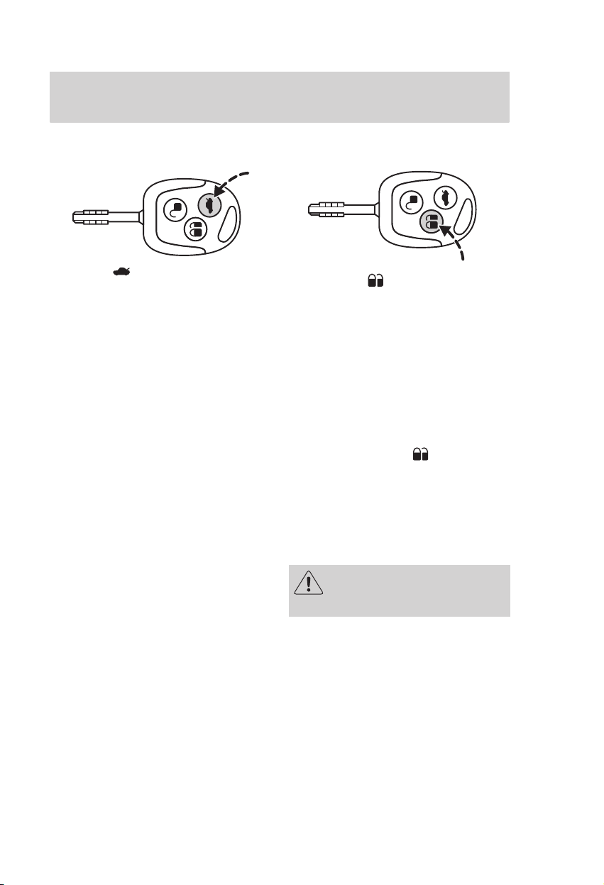
Radio frequency remote control
The vehicle or luggage
compartment will be
unlocked if the or button is
pressed unintentionally, without
the key being directed towards
the vehicle (e.g. in your pocket).
The luggage compartment can be
opened manually with the key or
with the remote luggage
compartment release.
The radio frequency used
by the remote control can
also be used by other short
distance radio transmissions (e.g.
amateur radios, medical
equipment, wireless headphones,
remote controls, alarm systems
etc.). If the remote control
frequencies are jammed, you will
not be able to use any remote
functions to lock or unlock the
vehicle or set the alarm. However,
you can lock/unlock with the key.
For type approval of your remote
control, refer to the table at the
back of the chapter Capacities
and specifications.
The system is operational
three seconds after the ignition has
been switched off. The range
between transmitter and vehicle is
environmentally influenced and
varies greatly.
65
Page 68

Controls and features
To unlock the doors
Pressing the button once
deactivates the double locking and
the anti-theft alarm system, and
also unlocks all doors. The
direction indicators will flash once.
Note: When is pressed, unless a
door or the luggage compartment is
opened, or the ignition is switched
on, central locking and the
anti-theft alarm system will
automatically be activated after
45 seconds.
Re-programming the unlocking
function
You can change the unlocking
function so that pressing the
button once deactivates the double
locking and the anti-theft alarm
system and unlocks the driver’s
door. Pressing the button twice
within three seconds also unlocks
the passengers’ doors.
In order to re-programme the
function, press and hold the and
buttons simultaneously for at
least four seconds with the ignition
switched off. The direction
indicators will flash twice to
indicate that the unlocking function
has been successfully
re-programmed.
Pressing and holding both buttons
simultaneously for at least four
seconds again will change the
function back.
66
Page 69
Controls and features
To unlock the tailgate
Press the button twice within
three seconds.
To lock
Pressing the button once
activates the central locking and
the anti-theft alarm system.
On vehicles not equipped with
double locking, the direction
indicators will flash twice to
confirm the system is operating. On
vehicles equipped with double
locking, the direction indicators will
not flash.
If, on vehicles equipped with
double locking, the button is
pressed twice within three seconds,
double locking and the interior
sensing alarm will be activated.
The direction indicators will flash
twice to confirm the system is
operating.
Double locking should not
be activated when persons
are inside the vehicle.
67
Page 70

Controls and features
Global opening/global closing
The system automatically opens/
closes all windows and the sunroof
from outside the vehicle.
Before operating power
windows or sunroof you
should verify they are free of
obstructions and ensure that
children and/or pets are not in
the proximity of window/sunroof
openings. Failure to do so could
result in serious personal injury.
It is the primary responsibility of
the supervising adults to never
leave a child unattended in a
vehicle and to never leave the
keys in an unattended vehicle.
Global opening
Pressing either the or the
button stops the opening function.
During global opening, the sunroof
will always open by sliding back
under the roof.
Global closing
To close, press and hold the
button for two seconds. Pressing
any button stops the closing
function. The anti-trap function is
also active during global closing.
For more information refer to the
sections Sunroof anti-trap
function and Smart windows.
To open, press and hold the
button for three seconds.
68
Take care when using global
closing. In an emergency,
press a button immediately to
stop.
Page 71

Controls and features
Key programming
A maximum of four keys with radio
frequency remote control
(including the ones delivered with
the vehicle) can be programmed.
1. To programme new keys with
radio frequency remote control
turn the ignition key to position II
four times within six seconds.
2. Switch off the ignition. A tone
sounds to indicate that it is now
possible to programme the keys for
10 seconds.
3. Press any button on a new key.
A tone will sound as confirmation.
Repeat this last step for all your
keys with radio frequency remote
control, including your original
keys.
4. Switch the ignition back on or
wait for ten seconds without
programming another key to end
the key programming. Only the
keys with radio frequency remote
control which you have just
programmed are now able to lock
and unlock your vehicle.
Note: To code keys for the engine
immobilisation system, refer to the
section Key coding.
Replacing the battery
If the range of the transmitter in
the key decreases gradually, the
battery (type 3V CR 2032) should
be replaced.
• Carefully separate the transmitter
unit from the key using a flat object
(e.g. a screwdriver) at the recess
on the back.
• Open the transmitter unit by
separating the retaining clips on
the sides with the flat object.
• Carefully prise out the battery
with the flat object. Fit the new
battery between the contacts with
the (+) sign facing upwards.
Reassemble the transmitter unit in
reverse order.
69
Page 72

Controls and features
ENGINE IMMOBILISATION
SYSTEM
The engine immobilisation system
is a theft protection feature which
prevents the engine from being
started with an incorrectly coded
key.
Keys
Your vehicle is supplied with coded
keys marked with a coloured dot.
Replacement keys must be recoded
together with your other keys.
Automatic arming
The system is armed five seconds
after switching off the ignition. The
indicator light will flash every
two seconds.
Automatic disarming
Switching on the ignition disarms
the system if the correct code is
recognised. The indicator light
illuminates for approximately
three seconds and then
extinguishes.
If the indicator light illuminates
constantly for one minute or flashes
for approximately one minute and
then repeatedly at irregular
intervals, the system did not
recognise the key code. Remove
the key and try again.
If a key with an incorrect code was
used, a waiting period of about
20 seconds is required before
starting the vehicle with a correctly
coded key.
70
Page 73

Controls and features
If the engine does not start, a
system malfunction has occurred.
Have the system checked by an
expert immediately.
To ensure a trouble-free
data exchange between the
vehicle and key, do not shield the
keys with any metal objects.
Key coding
A maximum of eight keys can be
coded using two other keys
previously coded for your vehicle.
Complete each of the following
steps within five seconds.
1. Insert the first key in the
ignition switch and turn to
position II.
2. Turn the key back to position 0
and remove from the ignition
switch.
3. Insert the second key in the
ignition switch and turn to
position II.
4. Turn the second key back to
position 0 and remove from the
ignition switch – the key coding
mode is now activated.
5. If an uncoded key is now
inserted in the ignition switch and
turned to position II within
10 seconds, this key is coded to the
system.
71
Page 74

Controls and features
6. After the coding process is
completed remove the key from the
ignition switch. Wait five seconds
for the system to be activated.
If coding is not completed
correctly, the indicator light flashes
after the ignition is switched on
with the newly coded key and the
engine will not start.
Repeat the coding process after
waiting 20 seconds with the
ignition switched on (position II).
If a key is lost, it is
imperative to erase and
recode the remaining keys.
Consult your Ford Dealer if you
now have only one valid key.
Coding erasure
With two keys coded for your
vehicle you can make all the other
coded keys unusable, e.g. after loss:
Complete each of the following
steps within five seconds.
Carry out the first four steps under
Key coding, then continue as
follows:
1. Insert the second key in the
ignition switch and turn to
position II.
2. Remove the key from the
ignition switch.
3. Insert the first key in the
ignition switch, turn to position II
and hold. The control light flashes
for five seconds.
4. If the ignition is switched off
during these five seconds, the
erasure process is terminated and
no key is erased.
5. If the erasure process is
completed, all the other keys, apart
from the two used for erasure, can
no longer be used unless recoded.
Additional keys can now be coded.
72
Page 75

Controls and features
ANTI-THEFT ALARM SYSTEM
The system is armed as soon as the
vehicle is locked and acts as a
deterrent to unauthorised persons
who attempt to open the doors,
bonnet or luggage compartment, or
remove the radio.
Activation
Turn the key as far as it will go in
the locked position and hold in this
position for one second.
Refer to the sections Central
locking with double locking
system and Radio frequency
remote control.
Automatic activation delay
The 20 seconds activation delay
begins when the bonnet, luggage
compartment and all doors are
closed.
Alarm
The alarm sounds for 30 seconds if
an unauthorised person opens a
door, the luggage compartment or
the bonnet. The hazard flasher
lights will flash for five minutes.
Any attempt to start the engine
without a valid key or to remove
the radio sounds the alarm again.
To switch off
The anti-theft alarm system can be
deactivated at any time – even
when the alarm is sounding – by
unlocking one of the front doors.
The anti-theft alarm system for the
tailgate is deactivated when the
luggage compartment is unlocked
with a key or the remote control.
After closure, the alarm is once
again armed.
ST170
On the ST170 with enhanced
security (certain markets only), the
anti-theft alarm system is
deactivated by pressing
remote control.
If the remote control is not
available or if the remote control
battery has been allowed to go flat,
the car may be used with a
non-remote key. Opening the
driver’s door with the mechanical
key starts a 12 second delay chime
before the alarm sounds. The alarm
system should be deactivated
during this period by turning the
key in the ignition to position II.
The car may now be driven as
normal without the alarm sounding.
on the
73
Page 76

Controls and features
ANTI-THEFT ALARM SYSTEM
WITH INTERIOR SENSORS
This system acts as a deterrent
against unauthorised intrusion by
sensing any movement within the
vehicle.
The sensors in the ST170 are
located in the interior light unit
(optional).
This system functions
correctly only if all windows
and the sunroof are completely
closed. In addition to this, the
sensors located at the top of the
door pillars must not be covered
up. The system adapts to
conditions in the vehicle’s interior
but it should not be activated if
any persons, animals or other
moving objects are inside the
vehicle.
Delayed activation and
confirmation of activation
This function is the same as the
anti-theft alarm system.
Alarm
Unauthourised entry into the
vehicle’s interior will trigger the
alarm in the same way as the
anti-theft system.
Additional heating system
Do not activate the interior
anti-theft alarm if an additional
heating system is used, as the
alarm could otherwise be set off.
Activation
The interior sensing alarm is
activated together with the double
locking system.
74
Page 77

Seating and safety restraints
SEATS
Sitting in the correct position
max. 30º
• Sit in an upright position with the
base of your spine as far back as
possible and with the backrest
reclined no more than 30 degrees.
• Adjust the head restraints so that
the top is level with the top of your
head.
• Do not move the front seat too
close to the instrument panel. The
driver should hold the steering
wheel in the ‘10 to 2 o’ clock’
position with arms slightly bent.
The legs should also be slightly
bent so that the pedals can be
pressed fully to the floor.
• The seat belt should cross the
centre of the shoulder; the lap strap
should fit tightly across the hips,
not the stomach.
Do not use any accessory
seat covers that are not
specifically designed for seats
with side air bags. These seat
covers must be fitted by properly
trained technicians.
Do not adjust the seats
while the vehicle is moving.
Moving the seats forwards or
backwards
Pull the lever. Rock the seat to
engage it in its catch.
75
Page 78

Seating and safety restraints
Adjusting the lumbar support
When the driver’s seat is equipped
with an armrest, the handwheel for
the lumbar support is located on
the side of the armrest.
Driver’s armrest
• Slowly raise the armrest to the
desired position .
Note: If the armrest is too high,
repeat the procedure.
Adjusting the height of the
manually operated driver’s seat
Adjusting the height of the
electrically operated driver’s
seat
To adjust the driver’s armrest to a
comfortable height:
• Pull the armrest all the way back,
past vertical .
• Push the armrest all the way
down, past horizontal .
76
Page 79

Seating and safety restraints
Heated front seats
The heated seats are operated by a
switch located in the centre
console. The light in the switch
indicates operation. The maximum
temperature is reached after five or
six minutes. It is regulated
thermostatically.
The heating will operate when the
ignition switch is in position II.
Heating with the engine off
will drain the battery.
Adjusting the angle of the
seatback
When the seats are slid fully
forward the backs can be fully
reclined.
Folding the seatback forwards
Pull the locking lever and fold the
seatback forwards.
Fold back the seatback until it
locks with a distinct click.
Do not place any objects
behind the seat which could
prevent the engagement of the
seat lock.
77
Page 80

Seating and safety restraints
Fold flat front passenger seat
To fold the front passenger seat
flat, pull the unlocking lever and
fold the seatback forwards until it
reaches the horizontal position.
The kangaroo net or utility bag can
be removed to provide a table
surface on the horizontal seatback.
Pull the unlocking lever to return
the seatback to the upright
position.
When returning the seatback to the
upright position, ensure that it
locks with a distinct click.
The front passenger seat
must be in the upright
position when driving if the seat
directly behind it is occupied.
For further information, refer to
Kangaroo net/utility bag in the
Controls and features chapter.
Head restraints
To raise: Pull the head restraint up.
To lower: Press the locking button
and push the head restraint down.
To remove the front seat head
restraints please consult an expert.
Rear head restraints can be
removed altogether if the locking
buttons are pressed.
Always have the rear head
restraint raised, when the
rear seat is occupied by a
passenger or a child restraint.
Do not place objects on the
table surface when driving
as these could become projectiles
in the event of an accident or
heavy braking.
78
Page 81

Seating and safety restraints
Head supports
The head supports on either side of
the front and rear passenger seat
head restraints can be folded
forwards.
Folding the rear seatbacks
forwards
3-, 5-door and Estate
4-door
Pull one or both unlocking knob(s)
in the luggage compartment and
fold the rear seatback forwards.
Returning the seatback to its
original position
Each seatback must engage in its
outer latch.
The seat belts must be forward of
the seatback.
Push the unlocking button on the
rear seatback and fold the rear
seatback forward.
79
Page 82

Seating and safety restraints
Folding the centre of the
seatback forwards
Pull the unlocking lever on the rear
seatback and fold the centre of the
seatback forwards.
When returning the seatback to the
upright position, ensure that it
clicks securely back into place.
Folding the seat cushion and
seatback forwards
Pull the loop between the seat
cushion and seatback, and fold the
seat cushion forward.
Remove the head restraint(s) of
the rear seat, and fold the seatback
forward.
Stow the head restraint(s) in the
plastic retainer(s) provided in the
now upright underside of the seat
cushion, as shown on the decal.
When returning the seats to their
original positions, make sure the
seat belts will function properly and
are positioned in front of the
seatback.
80
Page 83

Transporting luggage
Seating and safety restraints
Luggage and other loads
should be placed as low and
as far forward as possible within
the luggage compartment. Driving
with the tailgate/rear door open is
potentially dangerous as exhaust
fumes may be drawn into the
vehicle’s interior.
If objects have to be placed
in the passenger
compartment, secure them with
the seatbelts.
81
Page 84

Seating and safety restraints
SEAT BELTS
• Use seat belts at all
times.
• Never use a seat belt for more
than one person.
• Avoid wearing thick clothing.
• The seat belts should fit tightly
around the body.
Fastening the seat belts
Make sure that each seat belt uses
the correct buckle.
the rear seatback must be
correctly engaged.
In order to ensure that the
centre belt works properly,
Pull the belt out steadily. It may
lock if pulled sharply or if the
vehicle is on a slope.
Insert the tongue into the
buckle until a distinct click
is heard, otherwise the seat belt
will not be locked correctly.
To release the belt, press the red
button on the buckle and let the
belt rewind completely and
smoothly.
82
Do not recline the front seats
excessively as the belts provide
maximum protection when the
seats are in the near upright
position.
Page 85

Seating and safety restraints
Adjusting the height of the front
seat belts
To adjust, press the locking control
on the height adjuster and move
the pivot so that the belt rests
across the centre of the shoulder.
Pregnant Women
Pregnant women must wear
a correctly positioned seat
belt; it is safer for mother and
unborn child.
83
Page 86

Seating and safety restraints
The lap strap should be fitted
comfortably across the hips, low
beneath the pregnant abdomen.
The diagonal part of the seat belt
should be placed between the
breasts, and worn above and to the
side of the pregnant abdomen.
Always wear seat belts without
slack or twists. For optimum
protection, the seat belts should fit
tightly around the body. Do not
recline the front seats excessively,
as the belts provide maximum
protection when the seats are in
the near upright position.
Never wear just the lap
strap of a lap/shoulder
diagonal seat belt and never sit
on the lap strap using just the
shoulder strap. Both of these
actions are extremely dangerous
and may increase your risk of
serious injury.
Seat belt pretensioner
The belt pretensioners
must not be removed. If the
pretensioners deployed during an
accident, they must be replaced.
Have the pretensioners serviced
and disposed of by specially
trained personnel.
The restraint system, with belt
pretensioner in the front seat, helps
to reduce the risk of serious injury
in a head-on collision. During a
crash the seat belts are
pretensioned to help reduce slack
in the belt.
The belt pretensioner is only
triggered in major frontal collisions
provided the deployment threshold
is reached and the seat belt is
correctly engaged in the buckle.
Refer to the section Air bag for
further details.
84
Page 87

Seating and safety restraints
Care of seat belts
Periodically check the belts for
damage or fraying.
Do not attempt to repair or
lubricate retractor or
buckle mechanisms or to modify
the belts in any way.
Belts subjected to strain – as a
result of an accident – should be
renewed and the anchorages
checked by an expert.
Repositioning or uprating radio
speakers may adversely affect seat
belt operation. For further
guidance consult your dealer.
For information about cleaning the
seat belts, please refer to section
Cleaning the seat belts in the
chapter Maintenance and care.
85
Page 88
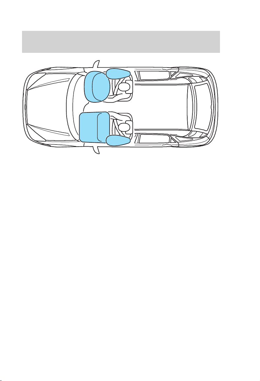
Seating and safety restraints
AIR BAG
The system
The air bag system comprises the
following:
• dual−stage inflatable air bags with
gas generators.
• side air bags.
• seat belt pretensioners.
• a variety of crash sensors.
• a warning light in the instrument
panel.
• an electronic control and
diagnostic unit.
Note: A loud bang will be heard
when an air bag deploys and it is
normal to see a cloud of harmless
powdery residue.
Front air bags
The seat and back must be set
correctly for the air bag to be
optimally effective. Refer to section
Sitting in the correct position at
the beginning of this chapter.
This is the ideal seating position for
driver and passenger and helps
reduce the risk of injury from
sitting too close to an inflating air
bag.
86
Page 89

Seating and safety restraints
Always wear the seat belt
and keep sufficient distance
between the driver and the steering wheel. Only when the seat
belt is used properly, can it hold
the body in a position which allows the airbag to achieve its
optimum effect.
There is a risk of injury when the
airbag deploys.
Do not modify the front of
the vehicle in any way as
this can adversely affect air bag
deployment.
The front air bags activate during
major collisions which are either
frontal or up to 30 degrees from
the left or the right. The air bags
inflate within a few thousandths of
a second. They will deflate on
contact with the front occupants
thus cushioning forward body
movement.
The front air bags are not
activated in minor collisions,
overturns, rear or side
collisions.
87
Page 90

Seating and safety restraints
Always keep the areas in
front of the air bags free.
Never affix anything to or over
these areas.
These areas should only be wiped
with a damp cloth, never with a wet
cloth.
Repairs to the steering
wheel, steering column and
air bag system should be carried
out by properly trained
technicians.
Side air bags
A label on the seatback indicates
that side air bags are fitted.
The side air bags are fitted on the
side of the seatbacks of the front
seats. In case of a severe lateral
collision, the air bag on the side
affected by the collision will be
inflated, even if the respective seat
is not occupied.
88
Page 91

Seating and safety restraints
The air bag will inflate between the
door panel and occupant. Once the
occupant’s body contacts the air
bag, the propellant escapes thereby
cushioning the impact.
The side bags are not activated
in minor lateral collisions,
front or rear collisions.
The crash sensors for the side air
bags are located under the
outboard side of the seats, fixed to
the floor. If water has entered the
floor area, do not start the vehicle.
Keep the sensors free from water,
heavy or sharp objects.
Repairs to either of the
front seat covers, the
sensors attached to the seats as
well as to the roof lining should
only be carried out by properly
trained technicians. Injuries may
result if the side air bags are
triggered inadvertently.
Do not block, obstruct or cover
the air bag because it may
prevent proper deployment.
Do not poke any sharp objects
into the areas where air bags are
fitted. This could damage the air
bags.
Do not use any accessory seat
covers that are not specifically
designed for seats with side air
bags. These seat covers must be
fitted by properly trained
technicians.
89
Page 92

Seating and safety restraints
Air bag/seat belt pretensioner
warning light
When the ignition switch is turned
to position II, the warning light in
the instrument cluster illuminates
for approximately three seconds to
indicate that the system is
functional.
If the warning light does not
illuminate, if it stays on or
illuminates intermittently or
continuously while driving, it
means there is a malfunction. Have
the system checked by an expert.
Child restraints
Baby safety seat
Driving direction
Extreme Hazard! Do not use
a child restraint on a seat
protected by an air bag in front of
it!
Original text according to
ECE R94.01:
Extreme Hazard! Do not use a
rearward facing child restraint
on a seat protected by an air
bag in front of it!
There is a risk of death or serious
injury when the air bag deploys.
90
Page 93

Seating and safety restraints
Whenever installing a child
seat/restraint, always read and
follow the manufacturer’s
instructions.
There is a risk of death or
serious injury when the
manufacturer’s instructions are
not followed properly or when the
child seat/restraint is modified in
any way.
Do not hold a child on your
lap while the vehicle is
moving.
Children of height 150 cm or under
or aged 12 years or under should
be secured in special restraints for
children, such as baby seats, child
safety seats or booster cushions.
Such equipment must be suitable
and government approved
(depending on country).
Together with the adult seat belt,
these restraints help to provide
maximum security for the children.
Note:
• If the vehicle has been involved in
an accident, have the child safety
seat checked by specially trained
technicians as it might be damaged.
• Do not leave unaccompanied
children in the child safety seat or
in the vehicle.
• When installing a child
seat/restraint with the seat belt,
always ensure belts fit without
slack or twists.
91
Page 94

Seating and safety restraints
Placement of child restraints
If your vehicle is equipped
with a front passenger air
bag, children of height 150 cm or
under or aged 12 years and under
must only be properly restrained
in the rear seat – never in the
front.
Child restraint positions
Mass group categories
0 0+ I II III
Seating positions
Front passenger X X X X X
Rear passenger
(central position)
Rear passenger
(side positions)
up to 10 kg
(about 0−9
months)
Baby safety seat
U U U U U
U U U U U
up to 13 kg
(about 0−2
years)
9-18 kg
(about 9
months −
4 years)
Child safety
seat
15-25 kg
(about
3!/2−12
years)
Booster seat/cushion
22-36 kg
(about
6−12 years)
U = Seat position suitable for
universal category restraints
approved for use in this mass/age
group.
X = Seat position not suitable for
children in this mass/age group.
Extreme Hazard! Do not use
a rearward facing child
restraint on a seat protected by
an air bag in front of it!
92
Page 95

Seating and safety restraints
Child restraints for different
mass groups
The correct restraint to be used
depends on the child’s age and
weight:
Baby safety seat
Driving direction
• Babies under approximately
two years and/or weighing less than
13 kg are best protected if carried
properly restrained in rearward
facing baby safety seats on the
rear seat.
Child safety seat
Driving direction
• Children under appoximately
four years and weighing between
13 and 18 kg should be carried
properly restrained in child safety
seats on the rear seat.
93
Page 96

Seating and safety restraints
Booster cushion
Driving direction
• Children between three and a half
and twelve years and weighing
between 15 and 36 kg should use a
booster cushion in the rear seat.
An adjustable auxiliary belt fixed to
the booster cushion ensures
optimum routing of the diagonal
belt over the shoulder. Make sure
that your child sits in an upright
position.
Never use a booster seat
with only a lap belt.
Never put the shoulder belt
under a child’s arm or
behind the back.
Never use pillows, books, or
towels to boost a child.
94
Page 97

Starting
GENERAL POINTS ON
STARTING
Do not operate the starter for
longer than 15 seconds at a time or
30 seconds for vehicles with diesel
engines. Release the ignition key as
soon as the engine has started.
If the engine has not started, return
the ignition key/ignition switch to
position 0 and repeat the starting
procedure.
If the engine does not start,
refer to the instructions
regarding the fuel injection
system shut-off switch on
page 115.
Vehicles with a petrol engine
If the battery has been
disconnected the vehicle may
exhibit some unusual driving
characteristics for approximately
5 miles (8 km) after battery
reconnection.
This is because the engine
management system must realign
itself with the engine. Any unusual
driving characteristics during this
period may be disregarded.
STARTING THE ENGINE
Vehicles with a petrol engine
Cold/hot engine
• Depress the clutch pedal fully
and start the engine without
touching the accelerator.
• If the engine does not start within
15 seconds, wait for a short period
and repeat the procedure.
• If the engine does not start after
three attempts wait 10 seconds
and follow the Flooded engine
procedure.
• If starting difficulty is
experienced at temperatures below
−25 ºC, depress the accelerator
pedal 1/4 to 1/2 of its travel to
assist starting.
Flooded engine
• Depress the clutch pedal fully.
• Slowly depress the accelerator
fully, hold it in this position and
start the engine.
• If the engine does not start
repeat the Cold/hot engine
procedure.
Engine speed limiter
The engine speed is limited
electronically to protect the engine.
95
Page 98

Starting
Vehicles with automatic
transmission
Brake pedal
The engine can be started only with
the selector lever in the N or P
position.
Your vehicle is fitted with an
additional selector lever locking
device which operates when the
selector lever is in the park
position.
After starting the engine, the lever
can be moved out of this position
only when the foot brake is
depressed and the locking
button pressed down.
Apply the handbrake or
depress the footbrake
before selecting a gear. Failure to
do so could result in the vehicle
pulling away when you have
engaged a gear.
Vehicles with a diesel engine
Cold/hot engine
• Depress the clutch pedal without
touching the accelerator.
• Turn the key to position II and
ensure the glow plug indicator light
illuminates.
Glow plug indicator light off
• Wait until the light extinguishes
before starting and continue
cranking without pausing until the
engine starts.
• If the engine stalls, repeat the full
starting procedure.
• At temperatures below −15ºC it
may be necessary to operate the
starter for up to 30 seconds. If
these weather conditions persist,
an engine block heater is
recommended.
A cold engine runs at a higher
idling speed after starting. This
causes a strong ‘creep’ tendency in
reverse and all forward gears.
96
Page 99

Switching off the engine
r
irst let the speed drop to idle ...
... and never depress the accelerato
Wait until the engine has reached
idle speed, then switch off.
If the engine is switched off at high
speed, the turbocharger will
continue running after the engine
oil pressure has dropped to zero.
This will lead to premature
turbocharger bearing wear.
Starting
97
Page 100

Driving
DRIVING WITH AUTOMATIC
TRANSMISSION
Moving off
With the engine idling and the
brake pedal depressed, move the
selector lever to one of the driving
positions. Release the brakes. The
vehicle will start to move slowly in
the selected direction. Depress the
accelerator pedal to increase speed.
It is not possible to tow
start or push start a vehicle
fitted with automatic
transmission. Use jump leads
attached to a booster battery.
Moving off in sand, mud and
snow
If the driving wheels are stuck, try
to rock the vehicle free by driving
forwards and backwards. To do
this, move the selector lever
alternately to D and R and depress
the accelerator as little as possible.
To increase the effect, move the
selector lever to R while the vehicle
is still moving forward and vice
versa.
To avoid excessive wear on the
transmission when shifting between
forward and reverse (rocking) keep
the engine speed as low as possible.
As an exception, position 2 may be
used for initial drive-off on icy or
snowy road surfaces.
98
 Loading...