

Page 1

Contents
Before driving
Introduction 2
Instrumentation 7
Controls and features 20
Seating and safety restraints 58
Starting and driving
Starting 77
Driving 81
Roadside emergencies 114
Servicing
Maintenance and care 126
Capacities and specifications 168
General maintenance information 175
Customer assistance 194
Reporting safety defects 204
Index 205
All rights reserved. Reproduction by any means, electronic or mechanical including
photocopying, recording or by any information storage and retrieval system or translation
in whole or part is not permitted without written authorization from Ford Motor Company.
Ford may change the contents without notice and without incurring obligation.
Copyright © 1999 Ford Motor Company
1
Page 2
Introduction
The following warning may be required by California law:
CALIFORNIA Proposition 65 Warning
Engine exhaust, some if its constituents, and certain vehicle
components contain or emit chemicals known to the State of
California to cause cancer, or birth defects or other reproductive harm.
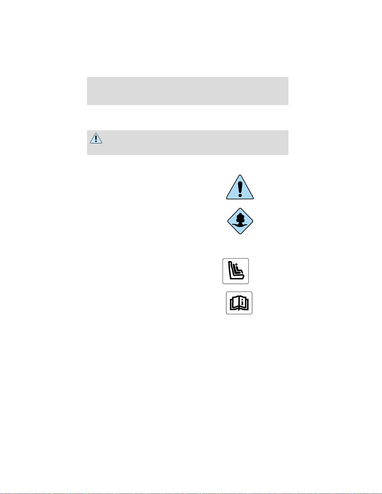
ICONS
Indicates a safety alert. Read the
following section on Warnings.
Indicates vehicle information related
to recycling and other
environmental concerns will follow.
Correct vehicle usage and the
authorized disposal of waste
cleaning and lubrication materials are significant steps towards
protecting the environment.
Indicates a message regarding child
safety restraints. Refer to Seating
and safety restraints for more
information.
Indicates that this Owner Guide
contains information on this subject.
Please refer to the Index to locate
the appropriate section which will
provide you more information.
WARNINGS
Warnings provide information which may reduce the risk of personal
injury and prevent possible damage to others, your vehicle and its
equipment.
2
Page 3

Introduction
INFORMATION ABOUT THIS GUIDE
The information found in this guide was in effect at the time of printing.
Ford may change the contents without notice and without incurring
obligation.
Federal Highway Administration regulation
Regulations such as those issued by the Federal Highway Administration
or issued pursuant to the Occupational Safety and Health Act (OSHA),
and/or state and local laws and regulations may require additional
equipment for the way you intend to use the vehicle. It is the
responsibility of the registered owner to determine the applicability of
such laws and regulations to your intended use for the vehicle, and to
arrange for the installation of required equipment. Your Ford dealer has
information about the availability of equipment which may be ordered for
your vehicle.
3
Page 4
Introduction
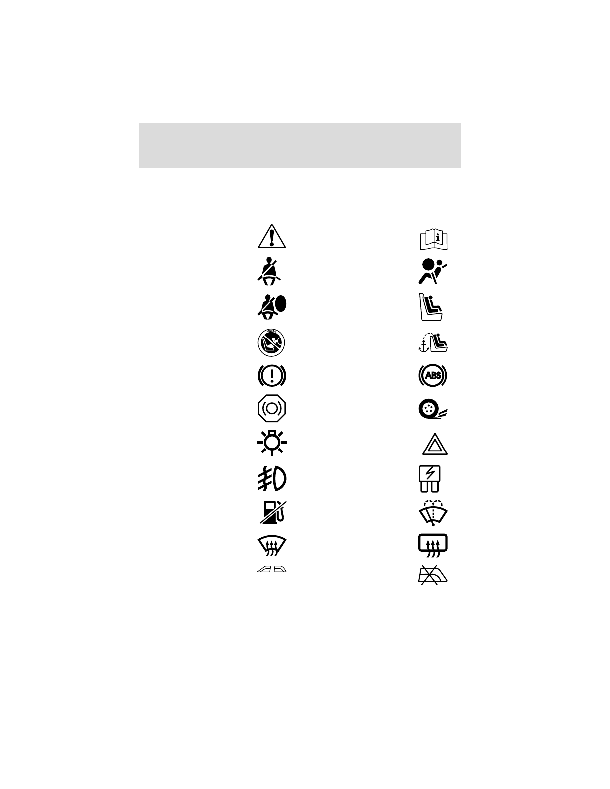
These are some of the symbols you may see on your vehicle.
Vehicle Symbol Glossary
Safety Alert
Fasten Safety Belt Air Bag-Front
Air Bag-Side Child Seat
Child Seat Installation
Warning
Brake System Anti-Lock Brake System
Brake Fluid Non-Petroleum Based
Master Lighting Switch Hazard Warning Flasher
Fog Lamps-Front Fuse Compartment
Fuel Pump Reset Windshield Wash/Wipe
See Owner’s Guide
Child Seat Tether
Anchorage
Traction Control
Windshield
Defrost/Demist
Power Windows
Front/Rear
4
Rear Window
Defrost/Demist
Power Window Lockout
Page 5
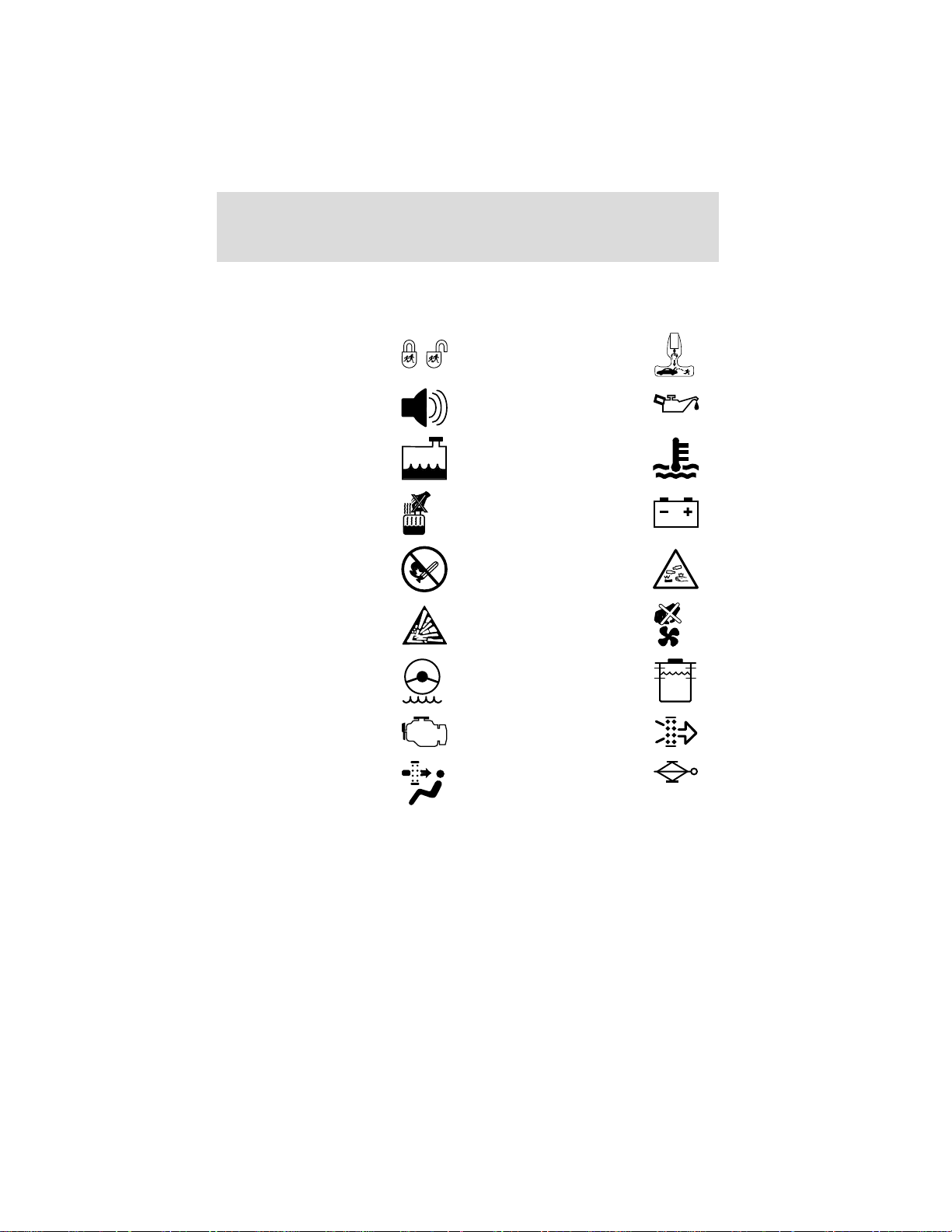
Vehicle Symbol Glossary
MAX
MIN
Introduction
Child Safety Door
Lock/Unlock
Interior Luggage
Compartment Release
Symbol
Panic Alarm Engine Oil
Engine Coolant
Engine Coolant
Temperature
Do Not Open When Hot Battery
Avoid Smoking, Flames,
or Sparks
Battery Acid
Explosive Gas Fan Warning
Power Steering Fluid
Maintain Correct Fluid
Level
Emission System Engine Air Filter
Passenger Compartment
Air Filter
Jack
5
Page 6

Introduction
ENTERING, EXITING AND/OR CLIMBING ON THIS VEHICLE
You must be careful and deliberate to minimize the possibility of personal
injury from a slip and fall when entering, exiting and/or climbing on this
vehicle. Always use the steps and assist handles before climbing. Do not
skip any steps or assist handles. Use three point contact at all times with
at least two feet and one hand or two hands and one foot firmly placed
during all phases of entering, exiting and/or climbing. Always keep your
shoe soles and hands clean. Keep the steps and assist handles free of
snow, ice, oil, grease, substances or debris. Be sure to use extra care in
bad weather. Avoid wearing thick gloves. Always perform trailer hook-up
while standing on the ground.
Do not carry items while entering, exiting, and/or climbing. Make
sure you keep a firm grip. Always FACE the VEHICLE STEP and
HANDLE SYSTEM while climbing up and down. Do not climb behind
the cab unless you have three point contact with a step and handle
system at all times.
6
Page 7

Instrumentation
7
Page 8
Instrumentation
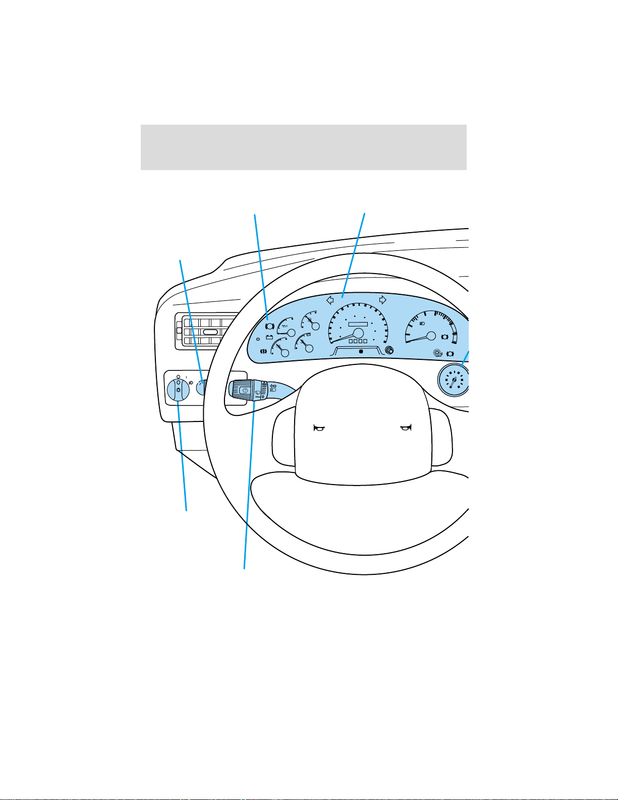
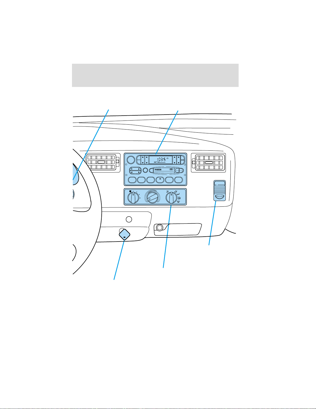
Panel dimmer control
(pg. 20)
P
Parking brake*
(hydraulic brake system)
(pg. 82)
E
K
A
R
B
P
L
E
K
A
R
B
+ -
!
8
1
E
K
A
R
B
AIR
CLEAN
8
ENGINE
PROTECT
H
Instrument cluster
(pg. 10)
50
40
8
0
6
00000
0
0
4
0
2
0000
PH
M
PRN 21
60
70
0
0
0
1
80
0
2
1
0
4
1
90
0
6
1
h
/
m
k
100
D
2
3
SERVICE
ENGINE
SOON
TRANS
TEMP
CRUIS
Y
L
N
O
L
E
U
F
L
E
S
IE
D
0
1
X
RPM
CHECK
TRANS
4
I
A
W
ABS
O
T
A
T
0
0
S
R
TE
A
W
R
ILE
A
TR
IN
L
E
U
F
S
B
A
9060
PSI
120
30
150
0
AIR
PRESSURE
1
0
STOP
ENGINE
30
F
E
20
H
10
0
C
Headlamp control
8
(pg. 20)
Turn signal and
wiper/washer control
(pg. 50)
Page 9
Instrumentation
Air pressure gauge*
(pg. 19)
VOL - PUSH ON
AM
BASS TREB BAL FADE
FM
E
IT
T
R
SEEK
TUNE
123456
APPLY
PULL TO
PARKING
BRAKE
PUSH TO
RELEASE
Electronic sound system
ST
FM1
SCAN
EJ
A/C
MAX
A/C
(pg. 26)
SIDE
REW FF
OFF
CLK
TAPE
AMS
1 - 2
POWER POINT
Auxiliary power point
(pg. 21)
Parking brake*
(air brake system)
(pg. 87)
Climate control system
(pg. 21)
*if equipped
9
Page 10
Instrumentation
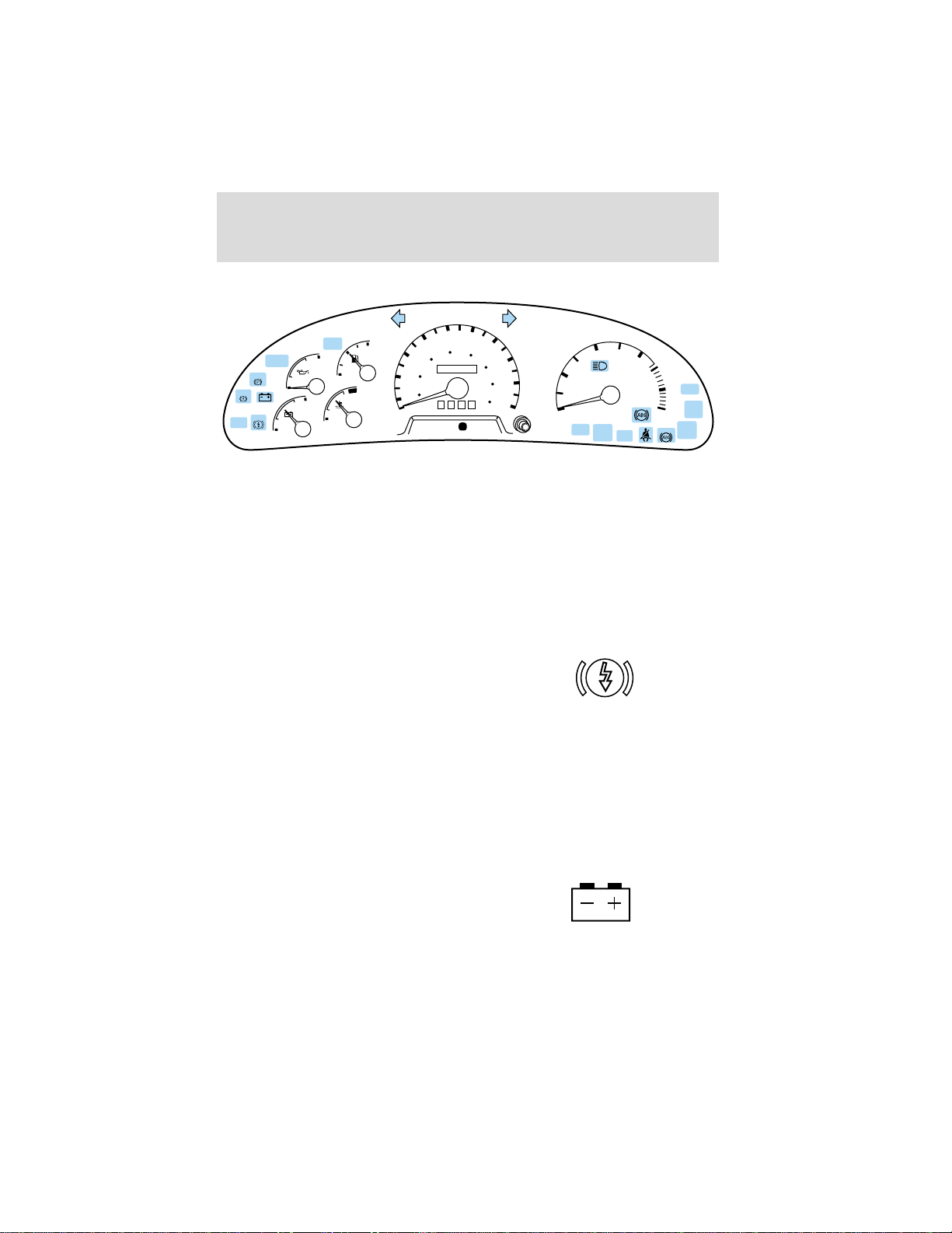
WARNING LIGHTS AND CHIMES
50
40
30
F
20
60
40
20
10
MPH
0
AIR
CLEAN
BRAKE
BRAKE
BRAKE
ENGINE
PROTECT
8
STOP
ENGINE
H
L
E
18
H
C
Air clean warning (if equipped)
Illuminates when the ignition is
turned to the ON position and the
engine is off. The light also
illuminates when the air system is
restricted (dirty, clogged).
Brake reserve system warning (if equipped)
Illuminates to indicate normal
Hydromax booster reserve system
activation when the engine is OFF
and the service brake pedal is
applied, or when the ignition is in
the ON or START position.
This light may also illuminate momentarily if the engine is running and
the driver turns the steering wheel fully in one direction while braking.
If the light remains on while the engine is running, this indicates
inadequate hydraulic booster pressure or reserve pump system failure.
Stop the vehicle safely as soon as possible and seek service immediately.
60
80
100
0
00000
0000
km/h
D
PRN 21
120
140
160
70
80
100
90
1
0
RANGE
INHIBIT
CLEAN
2
DIESEL FUEL ONLY
RPM
1000
X
SERVICE
ENGINE
CHECK
SOON
TRANS
AIR
BRAKE
3
4
CRUISE
WAIT
TO
START
WATER
TRAILER
IN
FUEL
Charging system
Illuminates when the ignition is
turned to the ON position and the
engine is off. The light also
illuminates when there is no
alternator output, or an over voltage
condition requiring electrical system service.
10
Page 11

Instrumentation
Parking brake warning (if equipped)
Momentarily illuminates when the
ignition is turned to the ON position
and the engine is off.
If the warning lamp remains
illuminated after engine start up,
this indicates a system failure in the master cylinder of the brake system.
Stop the vehicle safely as soon as possible and seek service immediately.
If equipped with an air brake system, the warning light stays on until the
air pressure builds up to 414 kPa (60 psi). If the air pressure drops
below 414 kPa (60 psi) durning operation, the remaining brake system is
still operational but the stopping distance will be greater.
Parking brake warning
Momentarily illuminates when the
ignition is turned to the ON position
and the engine is off. If the brake
warning lamp does not illuminate at
this time, seek service immediately.
Also illuminates when the parking
brake is engaged.
Engine protect warning (Cummins engine only)
Illuminates when there is a fault in
the electronic subsystem but the
vehicle can be driven, and indicates
one of the following conditions:
• low oil pressure
• low coolant level
• high coolant temperature
• high intake manifold temperature
Refer to the Engine Operator’s Manual.
BRAKE
!
BRAKE
P
ENGINE
PROTECT
11
Page 12
Instrumentation
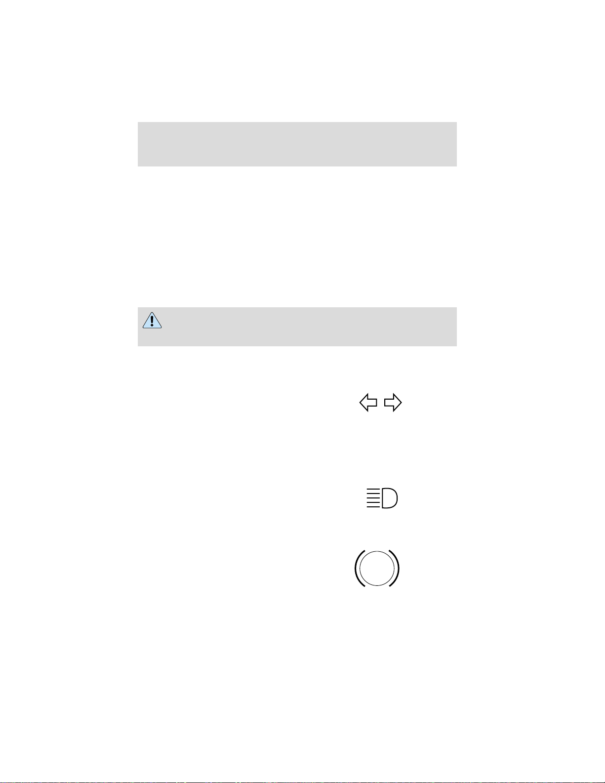
Stop engine (if equipped)
This light is used in conjunction
with the electronic engine control.
Refer to the Engine Operator’s
Manual for specific information
regarding this feature.
If the engine shuts down, it can be
restarted and operated for 30
seconds at a time or until the
problem is corrected. Refer to Engine shutdown system in the Starting
chapter.
Drivers of electronically controlled engines should know the
extent of warning engine shutdown system before operating the
vehicle. This information can be obtained from your dealer.
Turn signal
Illuminates when the left or right
turn signal or the hazard lights are
turned on. If one or both of the
indicators stay on continuously or
flash faster, check for a burned-out
turn signal bulb. Refer to Exterior bulbs in the Maintenance and care
chapter.
STOP
ENGINE
High beams
Illuminates when the high beam
headlamps are turned on.
Anti-lock brake system (ABS)
Momentarily illuminates when the
ignition is turned to the ON position
and the engine is off. If the light
remains on after the vehicle is
started, continues to flash or fails to
illuminate, have the system serviced immediately. With the ABS light on,
12
ABS
Page 13

Instrumentation
the anti-lock brake system is disabled and normal braking is still effective
unless the brake warning light also remains illuminated.
Wait to start
Indicates the air intake heater is in
operation and special starting
procedures are required. Refer to
the Starting chapter.
If equipped with an air
intake heater, DO NOT use
ether or any other starting fluids.
The use of starting fluids (ether)
in an engine equipped with an air
intake heater could result in
damage and/or personal injury.
Water in fuel (if equipped)
During refueling it is possible for
water-contaminated diesel fuel to be
pumped into your fuel tank. Your
vehicle fuel system is equipped with
a fuel filter/water separator to
remove water from the fuel. The
water in fuel indicator light
illuminates when the fuel
filter/water separator has a
significant quantity of water, or when the ignition key is switched to the
START position. If the light illuminates when the engine is running, stop
the vehicle as soon as safely possible, shut off the engine and drain the
filter bowl. Allowing water to stay in the system could result in extensive
damage to, or failure of, the fuel injection system.
To drain the fuel filter/water separator (refer to Maintenance and Care
section for procedure). Rotate the valve at the bottom of the filter
assembly allowing water to drain from the system. Close the valve upon
completion.
Do not drain water separator while engine is running. Fuel may
ignite if separator is drained while engine is running or vehicle is
moving.
WAIT
TO
START
WATER
IN
FUEL
13
Page 14

Instrumentation
Check trans (Allison automatic transmission)
The lamp will illuminate for several
seconds after the ignition is turned
to the ON position. Illumination of
this light indicates that a problem
has been detected and shifting may
be restricted. Depending upon the
severity of the problem, the
read-out digit on the shifter display
may be blank. Operation may
continue in order or reach service assistance. The ECU may not respond
to shift selector requests, since operating limitations are being placed on
the transmission, i.e. upshifts and downshifts may be restricted.
Direction changes will not occur.
Refer to the Maintenance and Care chapter.
Safety belt
Momentarily illuminates when the
ignition is turned to the ON position
to remind you to fasten your safety
belts. For more information, refer to
the Seating and safety restraints
chapter.
Service engine soon
The Service Engine Soon indicator
light illuminates when the ignition is
first turned to the ON position to
check the bulb. If it comes on after
the engine is started, one of the
engine’s control systems may be
malfunctioning. The light may illuminate without a driveability concern
being noted. The vehicle will usually be drivable and will not require
towing.
Temporary malfunctions may cause your Service Engine Soon light to
illuminate. Examples are:
1. The vehicle has run out of fuel. (The engine may misfire or run
poorly.)
2. Poor fuel quality or water in the fuel.
CHECK
TRANS
SERVICE
ENGINE
SOON
14
Page 15

Instrumentation
These and other temporary malfunctions can be corrected by filling the
fuel tank with good quality fuel. After three driving cycles without these
or any other temporary malfunctions present, the Service Engine Soon
light should turn off. (A driving cycle consists of a cold engine startup
followed by mixed city/highway driving.) No additional vehicle service is
required.
If the Service Engine Soon light remains on, have your vehicle serviced
at the first available opportunity.
Under engine misfire conditions, excessive exhaust temperatures
could damage the fuel system, interior floor coverings or other
vehicle components, possibly causing a fire.
Key-in-ignition warning chime
Sounds when the ignition key is left in the ignition in the OFF/LOCK or
ACC position and the driver’s door is opened.
Headlamps on warning chime
Sounds when the headlamps or parking lamps are on, the ignition is off
(and the key is not in the ignition) and the driver’s door is opened.
Safety belt warning chime
Sounds to remind you to fasten your safety belts.
For information on the safety belt warning chime, refer to the Seating
and safety restraints chapter.
15
Page 16
Instrumentation
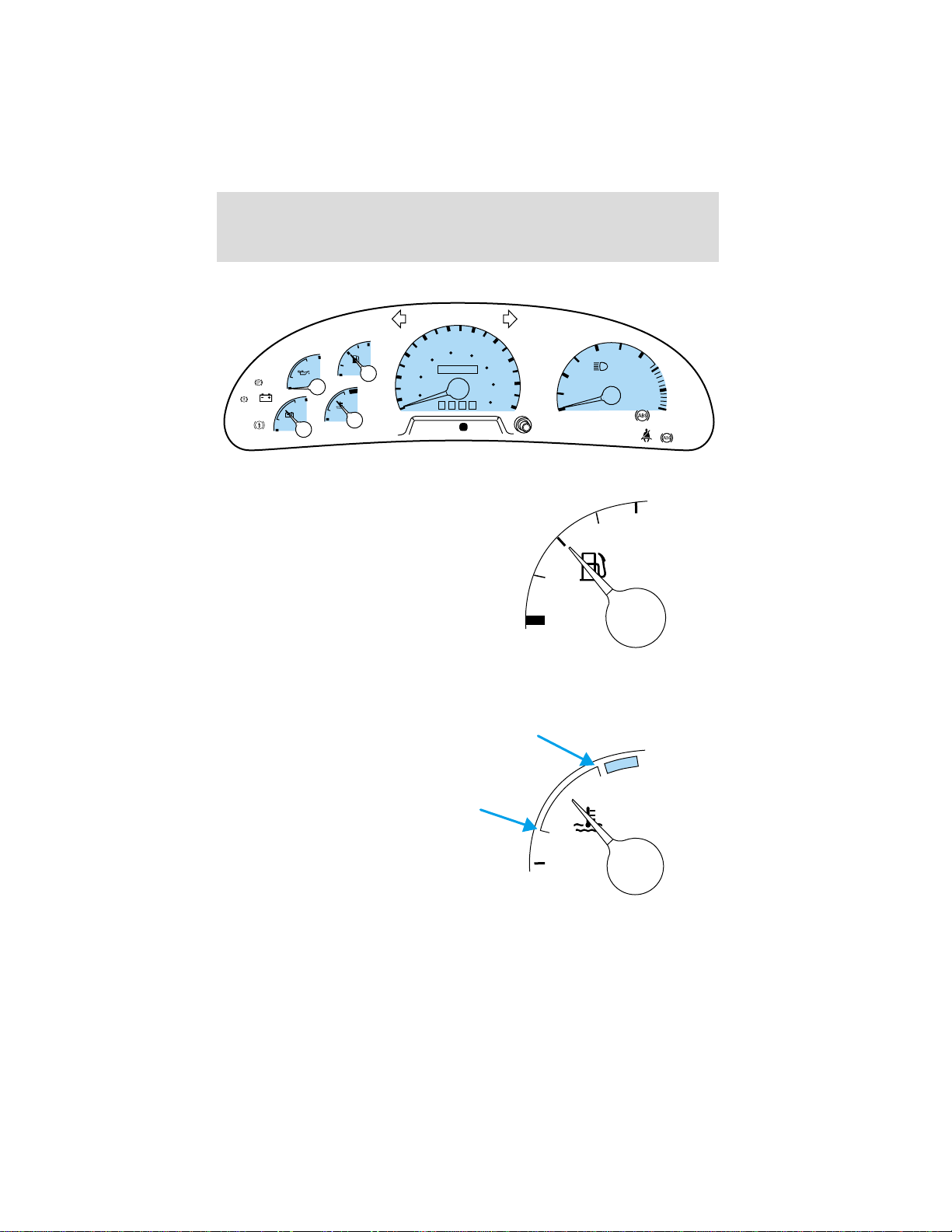
GAUGES
50
40
30
F
20
60
40
20
10
0
AIR
CLEAN
BRAKE
BRAKE
BRAKE
ENGINE
PROTECT
8
STOP
ENGINE
H
L
E
18
H
C
Fuel gauge
Displays approximately how much
fuel is in the fuel tank (when the
key is in the ON position). The fuel
gauge may vary slightly when the
vehicle is in motion. The ignition
should be in the OFF position while
the vehicle is being refueled. When
the gauge first indicates empty,
there is a small amount of reserve
fuel in the tank. When refueling the
vehicle from an empty indication, the amount of fuel that can be added
will be less than the advertised capacity due to the reserve fuel.
60
80
100
0
00000
0000
MPH
PRN 21
km/h
D
120
140
160
70
80
100
90
0
E
1
2
DIESEL FUEL ONLY
RPM
1000
X
RANGE
SERVICE
INHIBIT
ENGINE
SOON
CHECK
TRANS
F
3
4
CRUISE
WAIT
START
WATER
TRAILER
IN
FUEL
TO
Engine coolant temperature gauge
Indicates the temperature of the
engine coolant. At normal operating
temperature, the needle remains
within the normal area (the area
between the “H” and “C”). If it
enters the red section, the engine is
overheating. Stop the vehicle as
soon as safely possible, switch off
the engine immediately and let the
engine cool. Refer to Engine
coolant in the Maintenance and
care chapter.
16
H
C
Page 17
Instrumentation
Never remove the coolant reservoir cap while the engine is
running or hot.
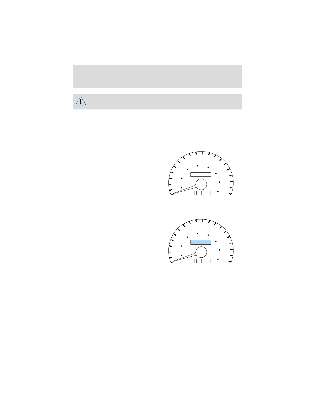
This gauge indicates the temperature of the engine coolant, not the
coolant level. If the coolant is not at its proper level the gauge indication
will not be accurate.
Speedometer
Indicates the current vehicle speed.
Odometer
Registers the total kilometers
(miles) of the vehicle.
20
10
20
10
40
30
40
20
0
40
30
40
20
0
60
0
MPH
60
000000
MPH
50
60
80
100
00000
0000
50
60
80
100
0000
km/h
km/h
120
120
70
140
160
70
140
160
80
90
100
80
90
100
17
Page 18
Instrumentation
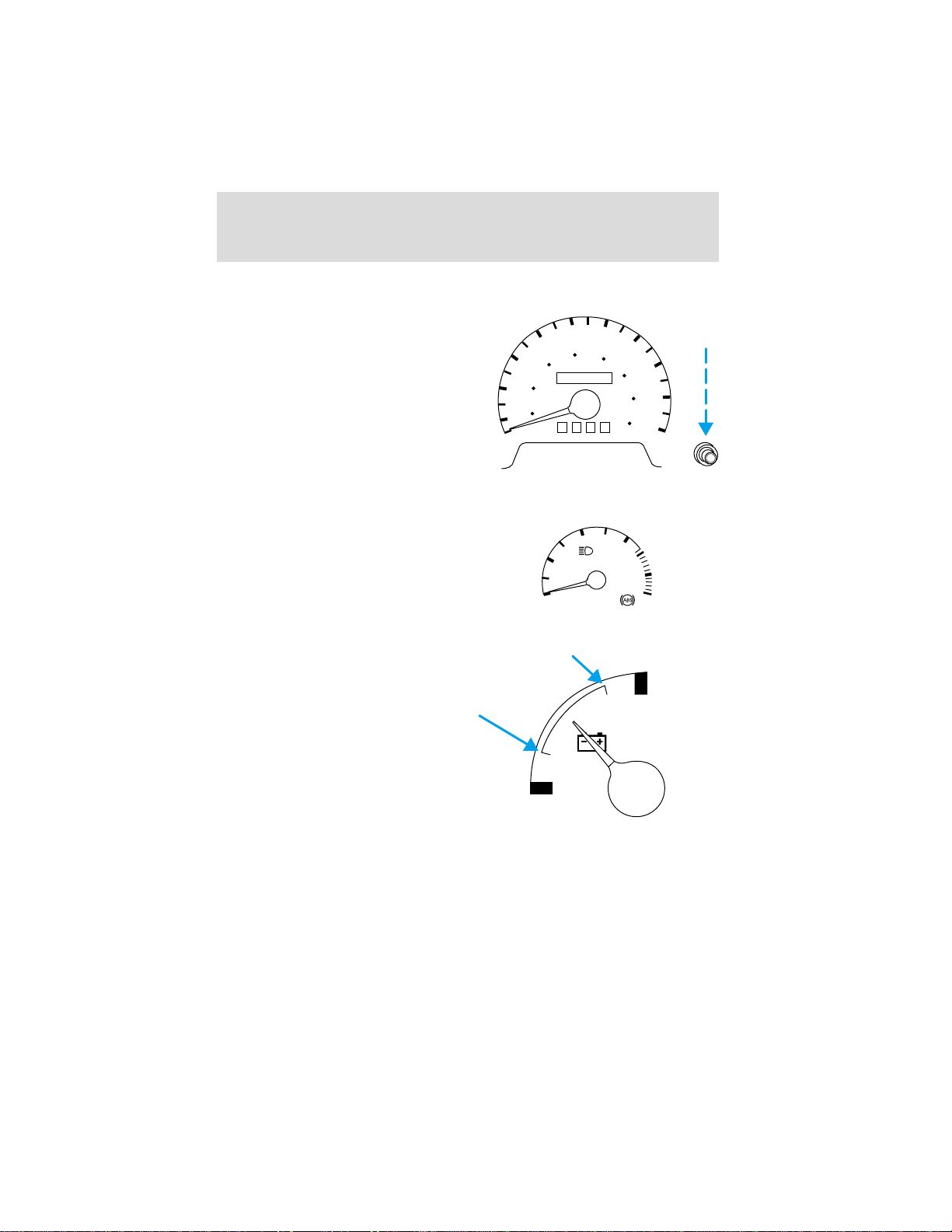
Trip odometer
Registers the kilometers (miles) of
individual journeys. To reset,
depress the control.
Tachometer
Indicates the engine speed in
revolutions per minute.
Driving with your tachometer
pointer in the red zone may damage
the engine.
Battery voltage gauge
This shows the battery voltage when
the ignition is in the ON position. If
the pointer moves and stays outside
the normal operating range (as
indicated), have the vehicle’s
electrical system checked as soon as
possible.
20
10
30
0
40
40
20
60
MPH
1
0
50
60
80
100
0
00000
0000
2
DIESEL FUEL ONLY
RPM
1000
X
km/h
70
120
140
160
3
18
80
90
100
4
18
8
Page 19

Instrumentation
Engine oil pressure gauge
This shows the engine oil pressure
in the system. Sufficient pressure
exists as long as the needle remains
in the normal range (the area
between the “L” and “H”).
If the gauge indicates low pressure,
stop the vehicle as soon as safely
possible and switch off the engine
immediately. Check the oil level.
L
Add oil if needed (refer to Engine
oil in the Maintenance and care
chapter). If the oil level is correct, have your vehicle checked at your
dealership or by a qualified technician.
Air pressure gauge and warning buzzer (if equipped)
Indicates the amount of air pressure
in the brake system (green=primary,
red=secondary) in pounds per
square inch. When the pressure is
too low for normal brake operation
(less than 414 kPa [60 psi]) and the
30
ignition is turned to ON:
• a warning buzzer sounds
• the warning light illuminates
0
PRESSURE
All vehicles have a dual-pointer air
pressure gauge to indicate the pressure in both brake circuits.
PSI
AIR
H
9060
120
150
Do not drive the vehicle when the low air pressure buzzer is
sounding or the warning light is lit. These warnings indicate
there is not enough air pressure for the brake system to operate
properly.
19
Page 20
Controls and features
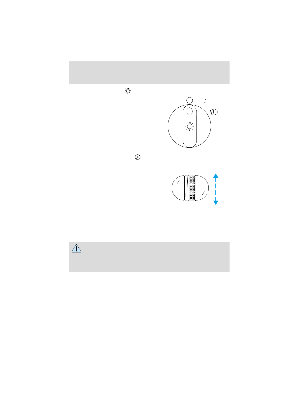
HEADLAMP CONTROL
Rotate the headlamp control to the
first position to turn on the parking
lamps. Rotate to the second position
to also turn on the headlamps.
PANEL DIMMER CONTROL
Use to adjust the brightness of the
instrument panel during headlamp
and parklamp operation.
• Rotate up to brighten.
• Rotate down to dim.
• Rotate to full up position (past
detent) to turn on interior lamps.
Daytime running lamps (DRL) (if equipped)
Turns the headlamps on with a reduced output. To activate:
• the ignition must be in the ON position and
• the headlamp control is in the OFF or Parking lamps position.
PANEL
P
DIM
Always remember to turn on your headlamps at dusk or during
inclement weather. The Daytime Running Light (DRL) System
does not activate your tail lamps and generally may not provide
adequate lighting during these conditions. Failure to activate your
headlamps under these conditions may result in a collision.
20
Page 21
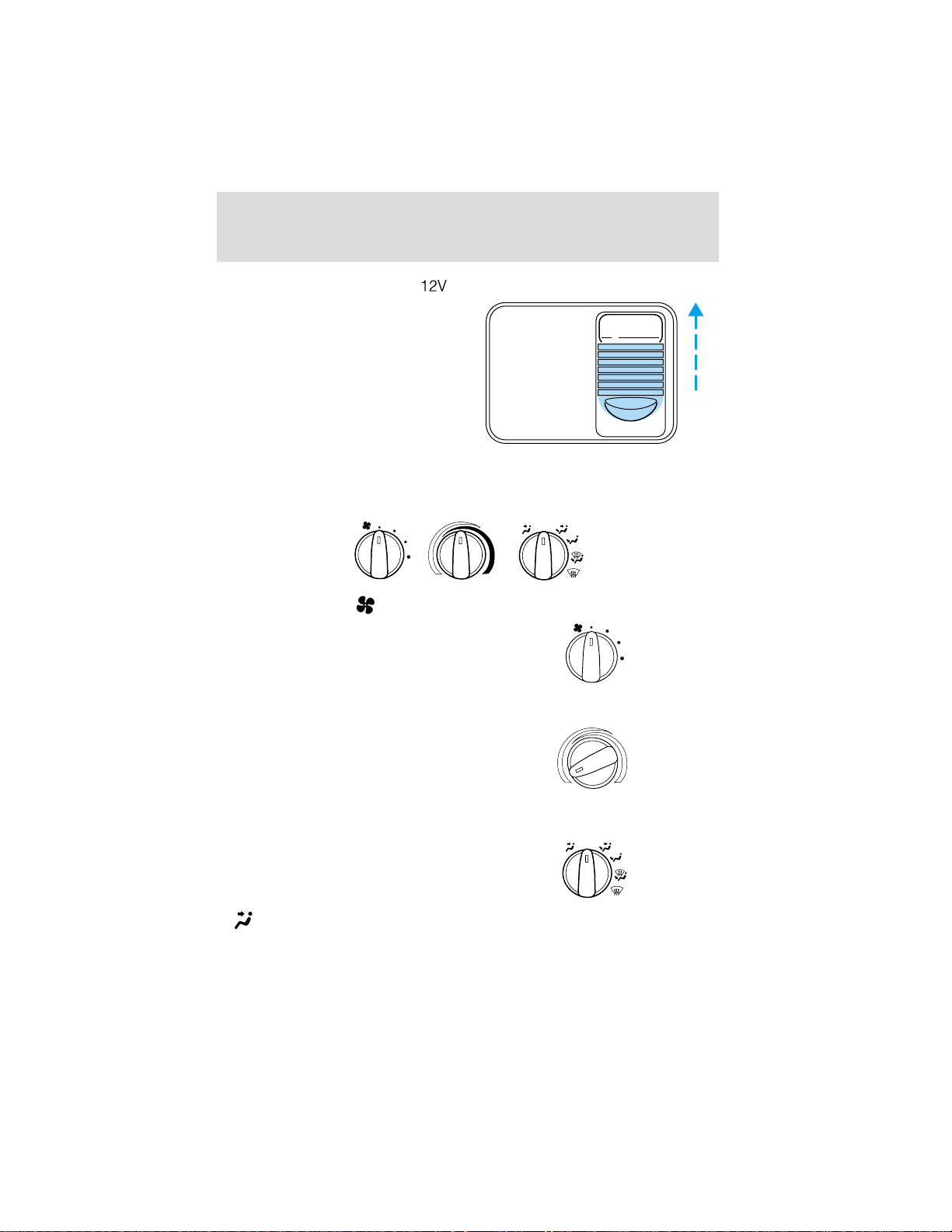
AUXILIARY POWER POINT
The auxiliary power point is located
on the instrument panel.
Do not plug optional electrical
accessories into the cigarette lighter.
Use the power point.
CLIMATE CONTROL SYSTEM
Heater only system (if equipped)
Fan speed control
Controls the volume of air circulated
in the vehicle.
Controls and features
POWER POINT
OFF
Temperature control
Controls the temperature of the
airflow inside the vehicle. On
heater-only systems, the air cannot
be cooled below the outside
temperature.
Mode selector control
Controls the direction of the airflow
to the inside of the vehicle.
•
(Panel) -Distributes outside air through the instrument panel
registers.
OFF
21
Page 22
Controls and features
• OFF-Outside air is shut out and the fan will not operate.
• (Panel and floor) -Distributes outside air through the instrument
panel registers and the floor ducts.
•
•
•
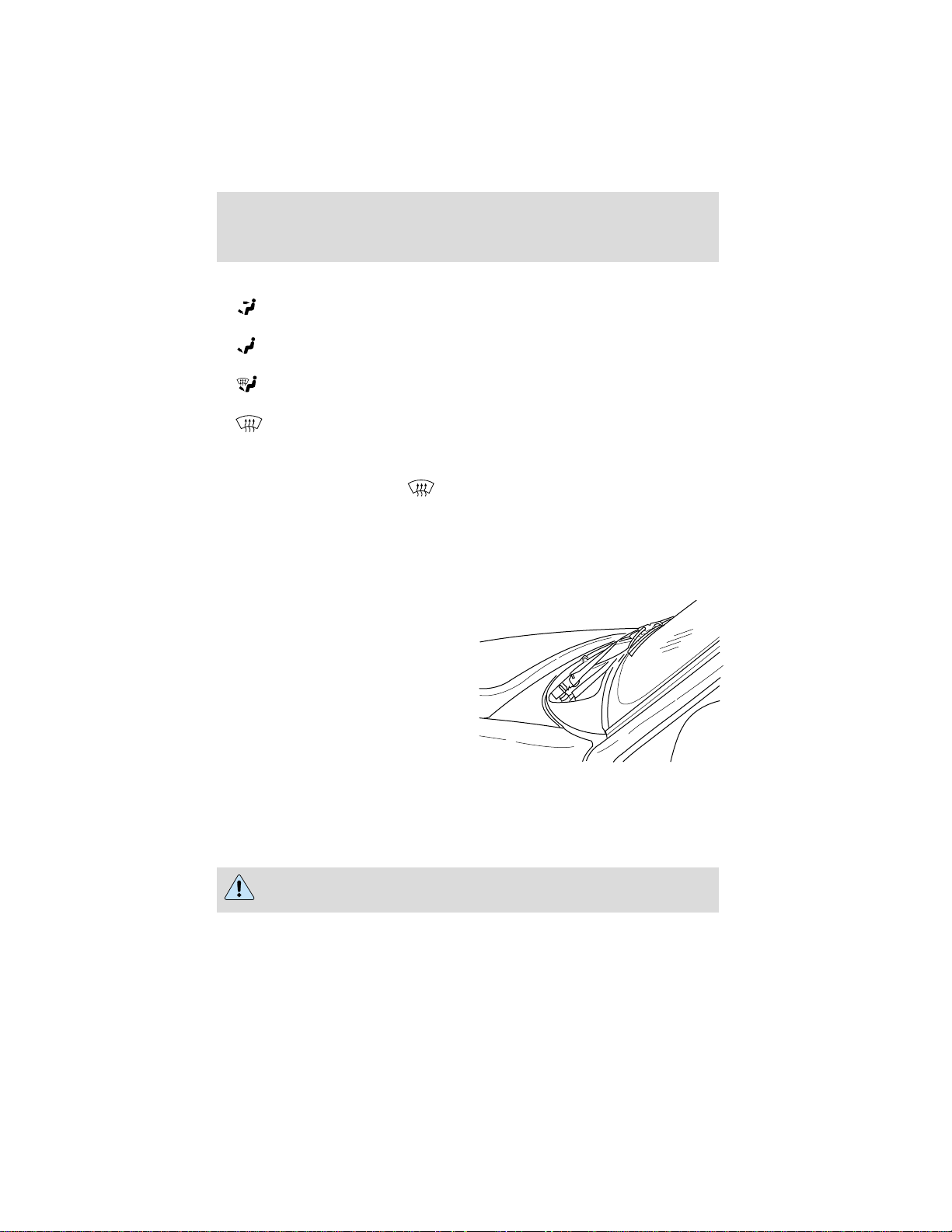
Operating tips
• In humid weather, select
• To reduce humidity buildup inside the vehicle, don’t drive with the
• Don’t put objects under the front seat that will interfere with the
• Remove any snow, ice or leaves
(Floor) -Allows for maximum heating. Distributes outside air
through the floor ducts.
(Floor and defrost) -Distributes outside air through the floor
ducts and the windshield defroster ducts.
(Defrost) -Distributes outside air through the windshield
defroster ducts. It can be used to clear ice or fog from the windshield.
before driving. This will reduce fogging
on your windshield. After a few minutes, select any desired position.
climate control system in the OFF position.
airflow to the rear seats (if equipped).
from the air intake area (at the
bottom of the windshield under
the hood).
• Do not place objects over the defroster outlets. These objects can
block airflow and reduce your ability to see through your windshield.
Also, avoid placing small objects on top of your instrument panel.
These objects can fall down into the defroster outlets and block
airflow and possibly damage your climate control system.
Do not place objects on top of the instrument panel, as these
objects may become projectiles in a collision or a sudden stop.
22
Page 23
Controls and features
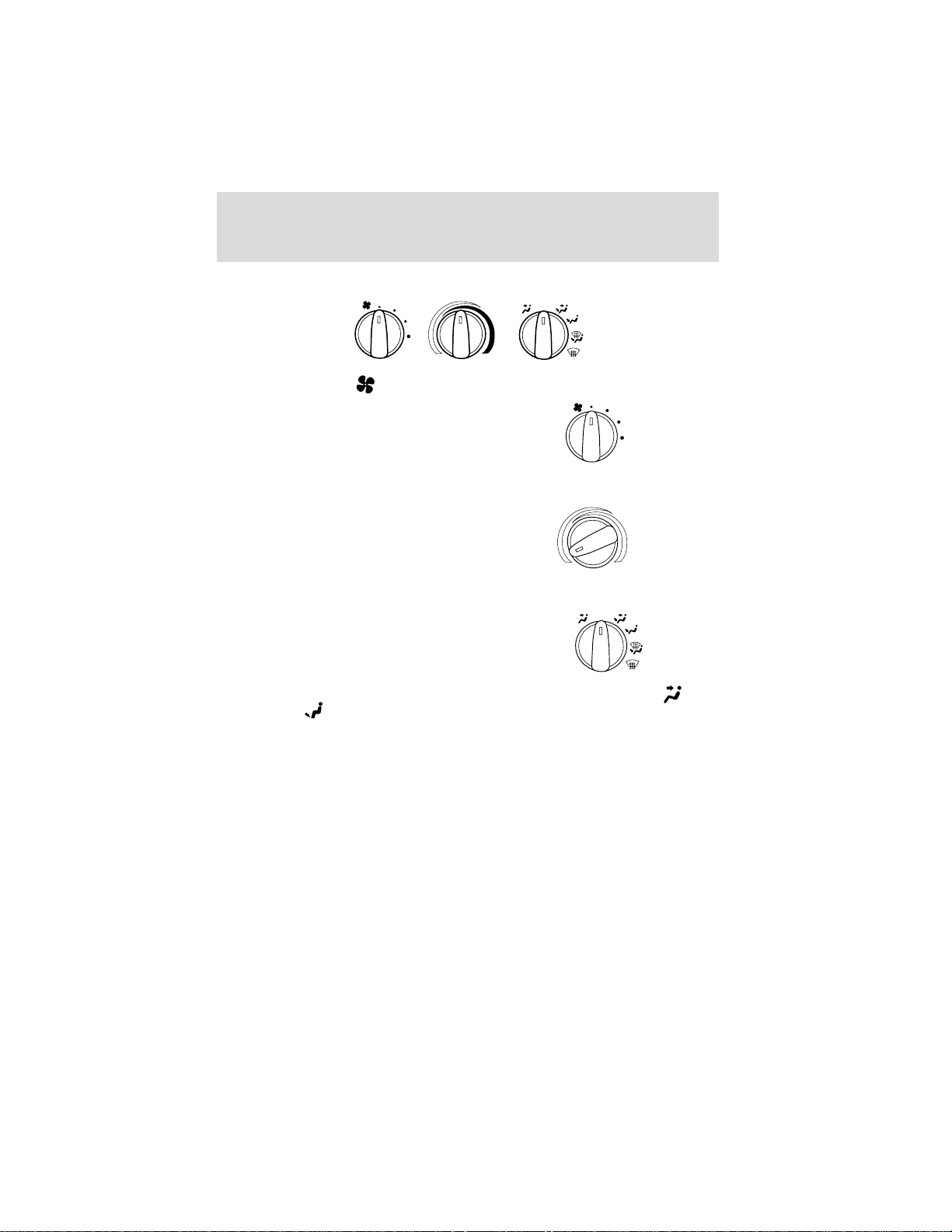
Manual heating and air conditioning system
OFF
A/C
MA
X
A/C
Fan speed control
Controls the volume of air circulated
in the vehicle.
Temperature control knob
Controls the temperature of the
airflow inside the vehicle.
Mode selector control
O
F
Controls the direction of the airflow
to the inside of the vehicle.
The air conditioning compressor will operate in all modes except
(Panel) and (Floor). However, the air conditioning will only function
if the outside temperature is about 10°C (50°F) or higher.
Since the air conditioner removes considerable moisture from the air
during operation, it is normal if clear water drips on the ground under
the air conditioner drain while the system is working and even after you
have stopped the vehicle.
• MAX A/C-Uses recirculated air to cool the vehicle. MAX A/C is noisier
than A/C but more economical and will cool the inside of the vehicle
faster. Airflow will be from the instrument panel registers. This mode
can also be used to prevent undesirable odors from entering the
vehicle.
• A/C-Uses outside air to cool the vehicle. It is quieter than MAX A/C
but not as economical. Airflow will be from the instrument panel
registers.
F
A/C
M
A
X
A
/C
23
Page 24

Controls and features
• (Panel) -Distributes outside air through the instrument panel
registers. However, the air will not be cooled below the outside
temperature because the air conditioning does not operate in this
mode.
• OFF-Outside air is shut out and the fan will not operate. For short
periods of time only, use this mode to prevent undesirable odors from
entering the vehicle.
•
•
•
•
Operating tips
• In humid weather, select
• To prevent humidity buildup inside the vehicle, don’t drive with the
• Don’t put objects under the front seat that will interfere with the
(Panel and floor) -Distributes outside air through the instrument
panel registers and the floor ducts. Heating and air conditioning
capabilities are provided in this mode. For added customer comfort,
when the temperature control knob is anywhere in between the full
hot and full cold positions, the air distributed through the floor ducts
will be slightly warmer than the air sent to the instrument panel
registers.
(Floor) -Allows for maximum heating by distributing outside air
through the floor ducts. However, the air will not be cooled below the
outside temperature because the air conditioning does not operate in
this mode.
(Floor and defrost) -Distributes outside air through the
windshield defroster ducts and the floor ducts. Heating and air
conditioning capabilities are provided in this mode. For added
customer comfort, the air distributed through the floor ducts will be
slightly warmer than the air sent to the windshield defroster ducts. If
the temperature is about 10°C (50°F) or higher, the air conditioner
will automatically dehumidify the air to reduce fogging.
(Defrost) -Distributes outside air through the windshield
defroster ducts. It can be used to clear ice or fog from the windshield.
If the temperature is about 10°C (50°F) or higher, the air conditioner
will automatically dehumidify the air to reduce fogging.
before driving. This will reduce fogging
on your windshield. After a few minutes, select any desired position.
climate control system in the OFF or MAX A/C position.
airflow to the rear seats (if equipped).
24
Page 25
Controls and features
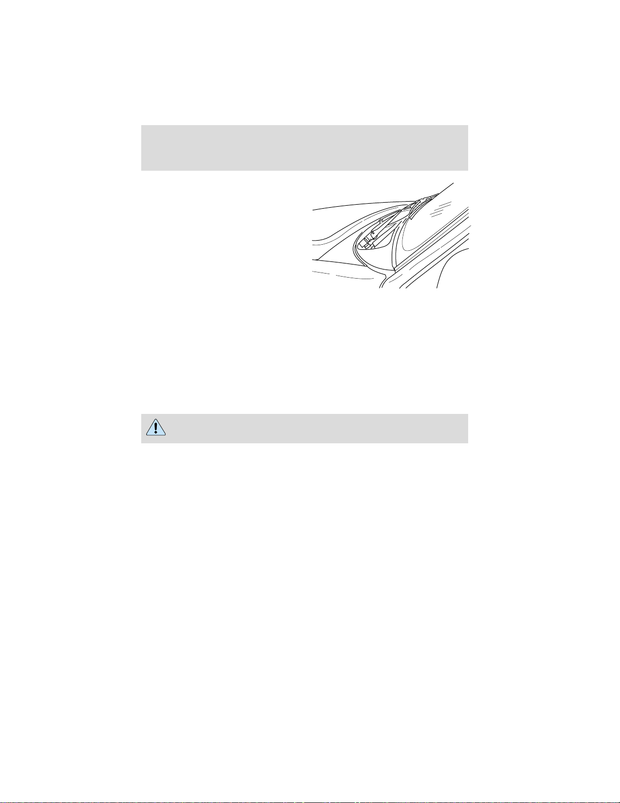
• Remove any snow, ice or leaves
from the air intake area (at the
bottom of the windshield under
the hood).
• If your vehicle has been parked with the windows closed during hot
weather, the air conditioner will do a much faster job of cooling if you
drive for two or three minutes with the windows open. This will force
most of the hot, stale air out of the vehicle. Then operate your air
conditioner as you would normally.
• Do not place objects over the defroster outlets. These objects can
block airflow and reduce your ability to see through your windshield.
Also, avoid placing small objects on top of your instrument panel.
These objects can fall down into the defroster outlets and block
airflow and possibly damage your climate control system.
Do not place objects on top of the instrument panel, as these
objects may become projectiles in a collision or sudden stop.
25
Page 26
Controls and features
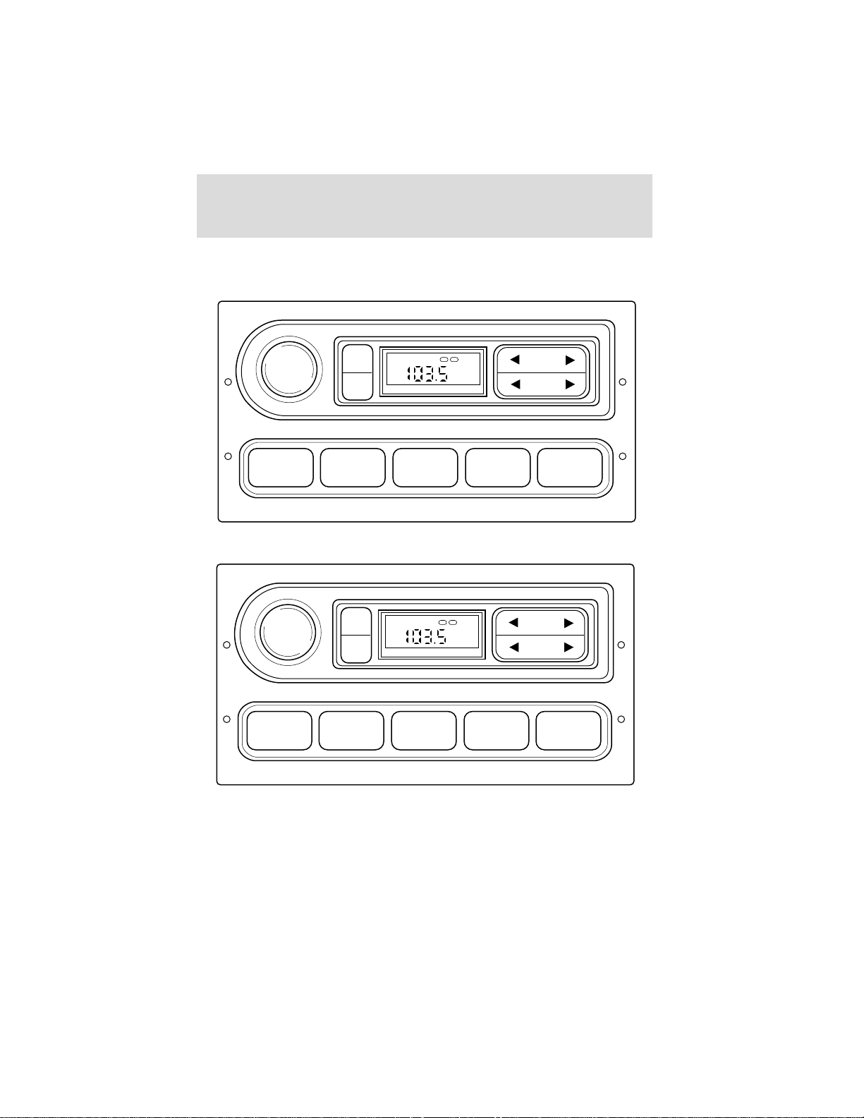
USING YOUR AUDIO SYSTEM
AM/FM Stereo
VOL
PUSH
ON
TONE
CLK
1 2 3 4 AM/FM
AM/FM Stereo
VOL
PUSH
ON
TONE
CLK
TONE VOL
TONE VOL
ST DX
ST DX
FM
12
FM
12
SEEK
TUNE
SEEK
TUNE
26
AM / FM STEREO
1 2 3 4 AM/FM
Page 27
Controls and features
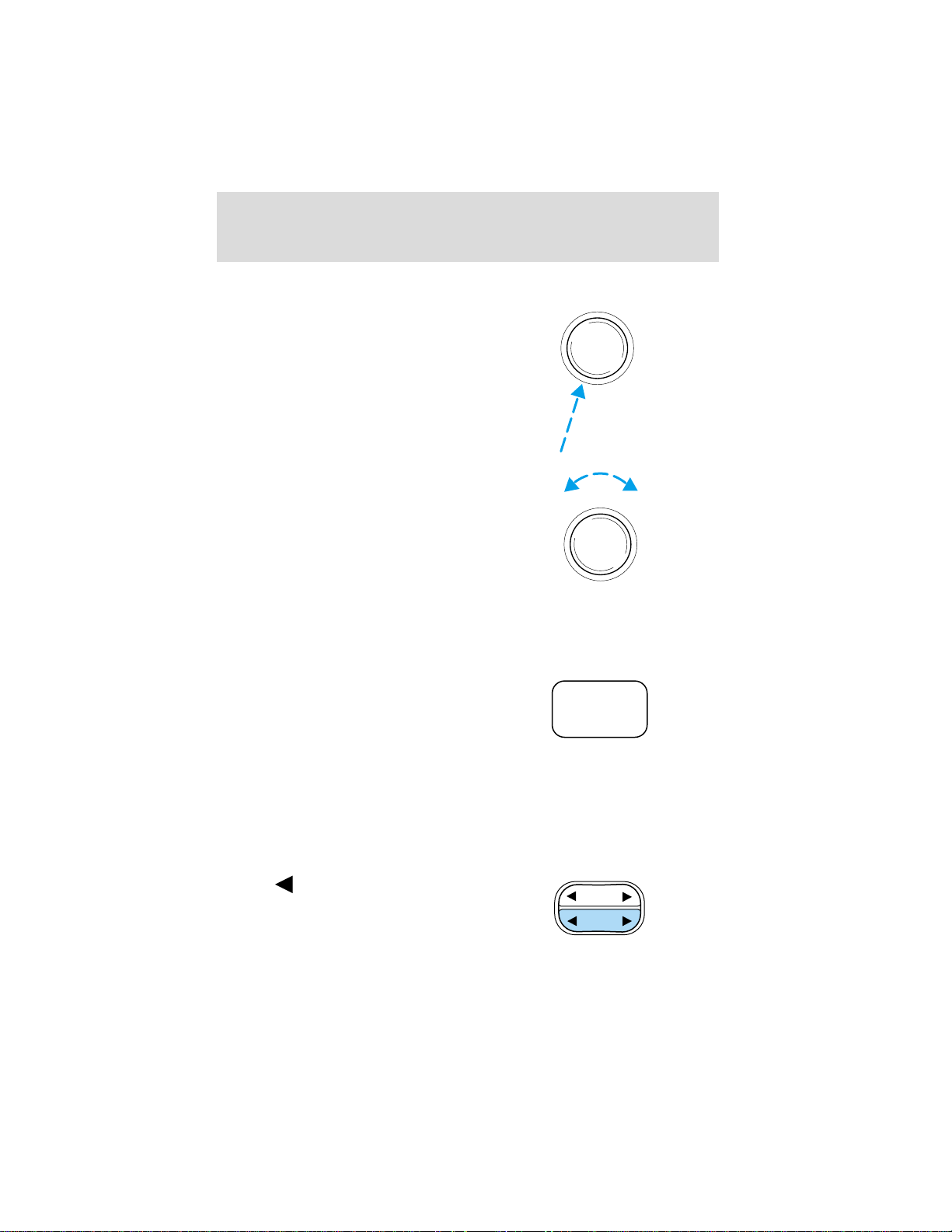
Volume/power control
Press the control to turn the audio
system on or off.
VOL
PUSH
ON
Turn the control to raise or lower
volume.
VOL
PUSH
ON
If the volume is set above a certain level and the ignition is turned off,
the volume will come back on at a “nominal” listening level when the
ignition switch is turned back on.
AM/FM select
The AM/FM select control works in
radio mode.
AM/FM
AM/FM select in radio mode
This control allows you to select AM or FM frequency bands. Press the
control to switch between AM, FM1 or FM2 memory preset stations.
Tune adjust
The tune control works in radio mode.
Tune adjust in radio mode
• Press
frequency down the band
(whether or not a listenable
to move to the next
SEEK
TUNE
station is located there). Hold the
control to move through the frequencies quickly.
27
Page 28

Controls and features
• Press to move to the next frequency up the band (whether or not
a listenable station is located there). Hold for quick movement.
Seek function
The seek function control works in radio mode.
Seek function in radio mode
• Press
listenable station down the
frequency band.
• Press
listenable station up the
frequency band.
Radio station memory preset
The radio is equipped with four station memory preset controls. These
controls can be used to select up to four preset AM stations and eight
FM stations (four in FM1 and four in FM2).
Setting memory preset stations
1. Select the frequency band with the AM/FM select control.
2. Select a station. Refer to Tune adjust or Seek function for more
information on selecting a station.
3. Press and hold a memory preset control until the sound returns,
indicating the station is held in memory on the control you selected.
to find the next
to find the next
SEEK
TUNE
1 2 3 4
Bass adjust
The bass adjust control allows you
to increase or decrease the audio
system’s bass output.
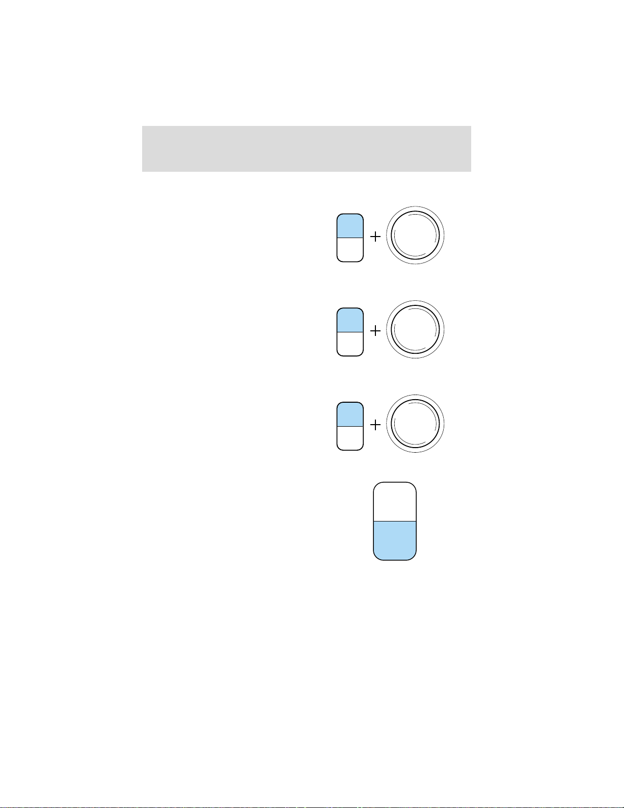
Press the TONE control once, then
use the volume knob to adjust the
desired level.
28
TONE
CLK
VOL
PUSH
ON
Page 29
Treble adjust
The treble adjust control allows you
to increase or decrease the audio
system’s treble output.
Press the TONE control twice, then
use the volume knob to adjust the
desired level.
Speaker balance adjust
Speaker sound distribution can be
adjusted between the right and left
speakers.
Press the TONE control three times,
then use the volume knob to adjust
the desired level.
Speaker fade adjust (if equipped)
Speaker sound can be adjusted
between the front and rear
speakers.
Press the TONE control four times,
then use the volume knob to adjust
the desired level.
Controls and features
VOL
PUSH
ON
TONE
CLK
VOL
PUSH
ON
TONE
CLK
VOL
PUSH
ON
TONE
CLK
Setting the clock
Press CLK to toggle between
listening frequencies and clock
mode.
TONE
CLK
29
Page 30
Controls and features
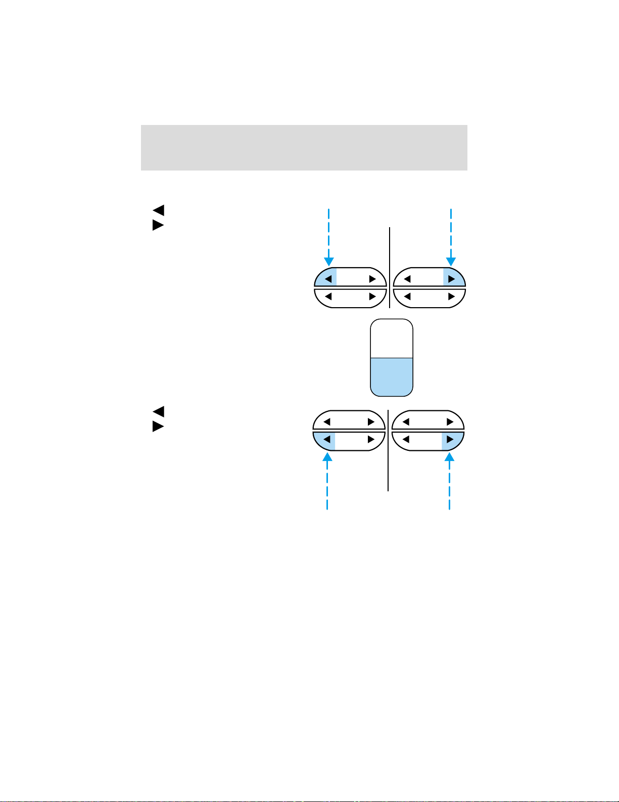
To set the hour, press and hold the CLK control until CLOCK SET
appears in the display and press the SEEK control:
•
•
To set the minute, press and hold
the CLK control until CLOCK SET
appears in the display and press the
TUNE control:
to decrease hours and
to increase hours.
SEEK SEEK
TUNE TUNE
TONE
CLK
•
• to increase minutes.
The CLK control will allow you to
switch between media display mode
(radio station, stereo information,
etc.) and clock display mode (time).
When in clock mode, the media
information will display for ten
seconds, when the radio is turned
on, and then revert to clock
information. Anytime that the media is changed, (new radio station,
etc.), the media information will again display for ten seconds before
reverting back to the clock. In media mode, the media information will
always be displayed.
30
to decrease minutes and
SEEK
TUNE
SEEK
TUNE
Page 31
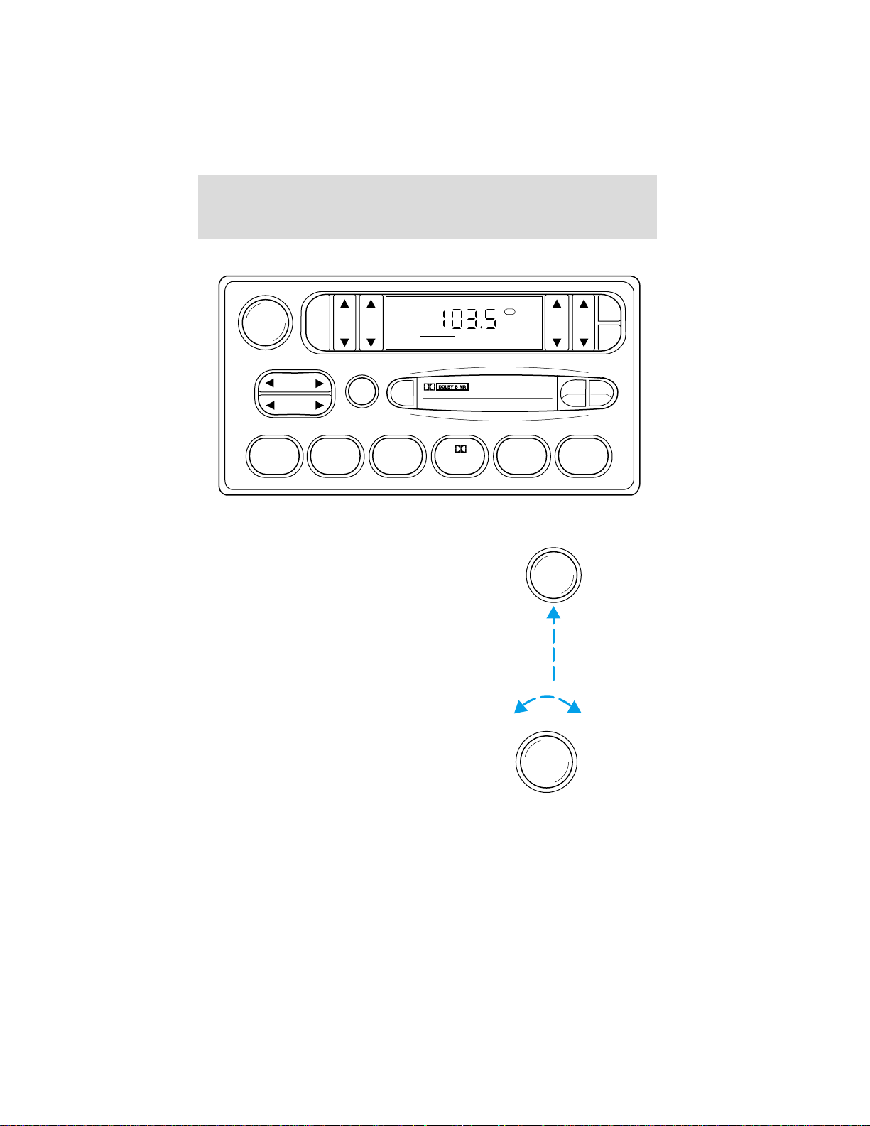
AM/FM stereo cassette
VOL - PUSH ON
AM
BASS TREB BAL FADE
FM
Controls and features
FM1
ST
CLK
TAPE
AMS
SEEK
TUNE
SCAN
EJ
123456
Volume/power control
Press the control to turn the audio
system on or off.
Turn the control to raise or lower
volume.
SIDE
REW FF
VOL - PUSH ON
VOL - PUSH ON
1 - 2
If the volume is set above a certain level and the ignition is turned off,
the volume will come back on at a “nominal” listening level when the
ignition switch is turned back on.
31
Page 32
Controls and features
AM/FM select
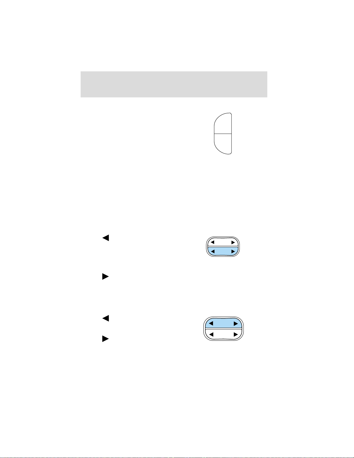
The AM/FM select control works in
radio and tape modes.
AM
FM
AM/FM select in radio mode
This control allows you to select AM or FM frequency bands. Press the
AM control to select from AM selections, and press the FM control to
select from FM1 or FM2 memory preset stations.
AM/FM select in tape mode
Press this control to stop tape play and begin radio play.
Tune adjust
The tune control works in radio mode.
Tune adjust in radio mode
• Press
frequency down the band
(whether or not a listenable
station is located there). Hold the
control to move through the
frequencies quickly.
• Press
a listenable station is located there). Hold for quick movement.
Seek function
The seek function control works in radio mode.
Seek function in radio mode
• Press
listenable station down the
frequency band.
• Press
listenable station up the
frequency band.
to move to the next
to move to the next frequency up the band (whether or not
to find the next
to find the next
SEEK
TUNE
SEEK
TUNE
32
Page 33
Controls and features
Scan function
The scan function works in radio
mode.
Scan function in radio mode
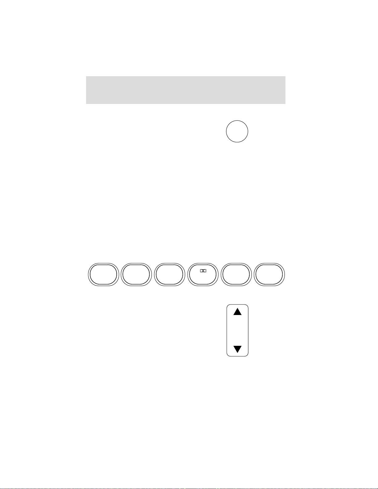
Press the SCAN control to hear a brief sampling of all listenable stations
on the frequency band. Press the SCAN control again to stop the scan
mode.
Radio station memory preset
The radio is equipped with six station memory preset controls. These
controls can be used to select up to six preset AM stations and twelve
FM stations (six in FM1 and six in FM2).
Setting memory preset stations
1. Select the frequency band with the AM or the FM select control.
2. Select a station. Refer to Tune adjust or Seek function for more
information on selecting a station.
3. Press and hold a memory preset control until the sound returns,
indicating the station is held in memory on the control you selected.
SCAN
123456
Bass adjust
The bass adjust control allows you
to increase or decrease the audio
system’s bass output.
BASS
33
Page 34
Controls and features
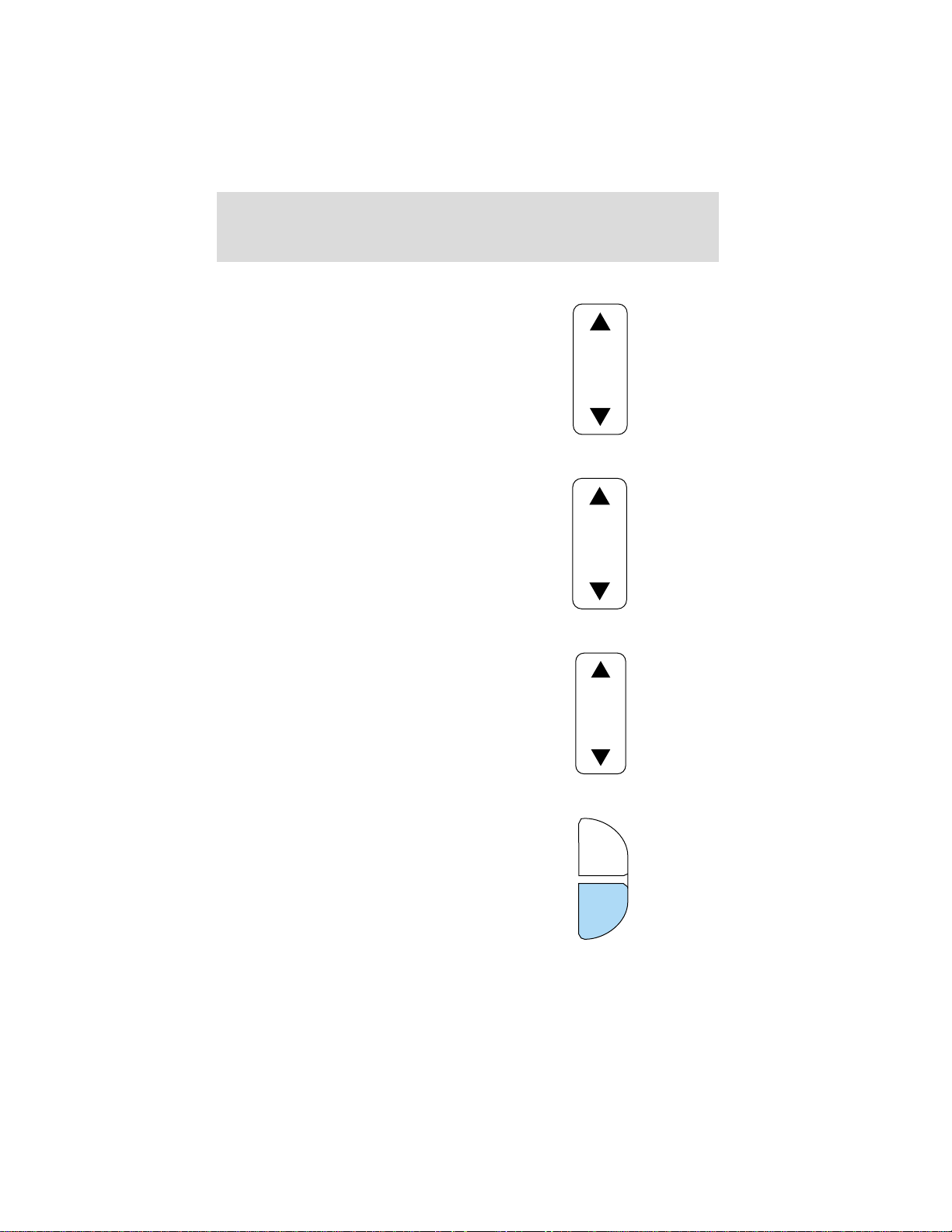
Treble adjust
The treble adjust control allows you
to increase or decrease the audio
system’s treble output.
Speaker balance adjust
Speaker sound distribution can be
adjusted between the right and left
speakers.
Speaker fade adjust
Speaker sound can be adjusted
between the front and rear
speakers.
TREB
BAL
FADE
Tape select
• To enter tape mode while in radio
mode, press the TAPE AMS
control.
34
CLK
TAPE
AMS
Page 35
Controls and features
Automatic Music Search
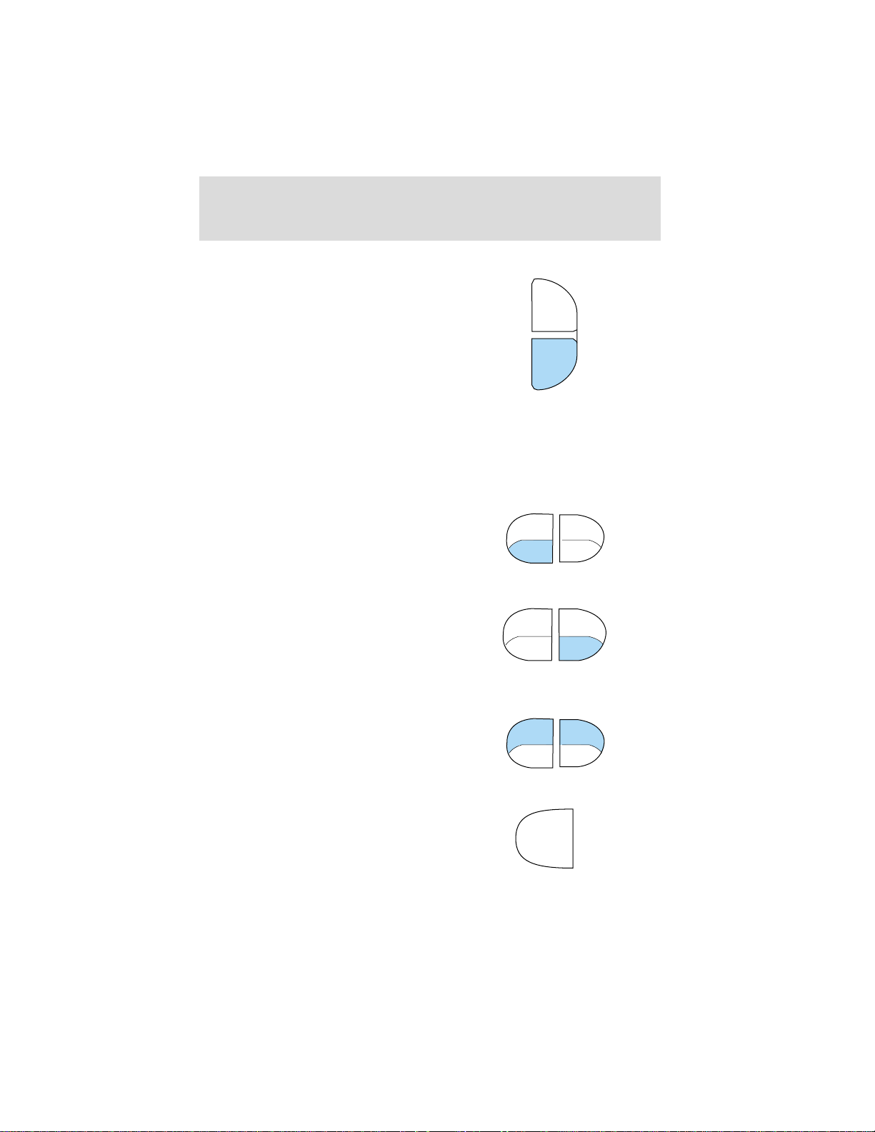
The Automatic Music Search feature
allows you to quickly locate the
beginning of the tape selection
being played or to skip to the next
selection.
To activate the feature, momentarily
depress the TAPE AMS button.
Then, press either REW (for the
beginning of the current selection) or FF (to advance to the next
selection). The tape deck stops and returns to play mode when the AMS
circuit senses a blank section on the tape.
In order to ensure proper operation of the AMS feature, the tape MUST
have a blank section of at least four seconds duration between programs.
Rewind
The rewind control works in tape
mode.
To rewind in tape mode, press the
REW control.
Fast forward
The fast forward control works in
tape mode.
• In the tape mode, tape direction
will automatically reverse when
the end of the tape is reached.
Tape direction select
Press SIDE and 1–2 at the same
time to play the alternate side of a
tape.
CLK
TAPE
AMS
SIDE
REW FF
SIDE
REW FF
SIDE
REW FF
1 - 2
1 - 2
1 - 2
Eject function
Press the control to stop and eject a
tape.
EJ
35
Page 36
Controls and features
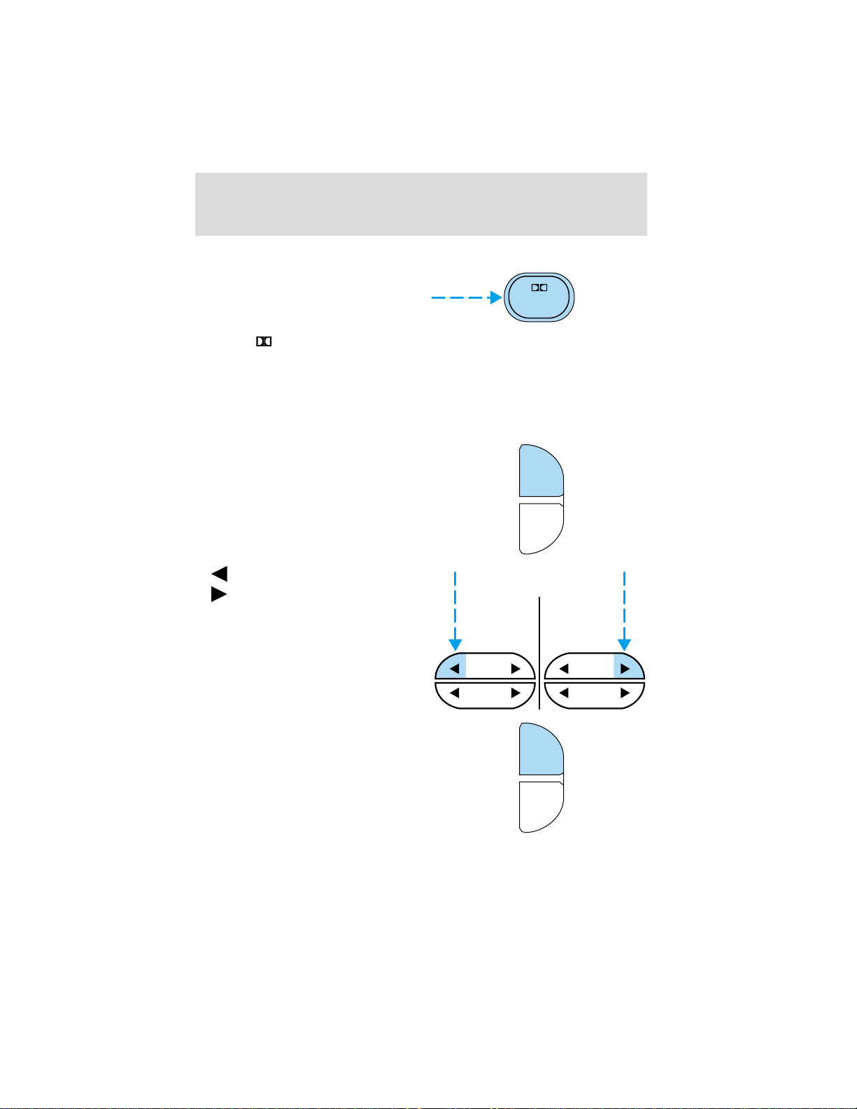
Dolby姞 noise reduction
Dolby威 noise reduction operates
only in tape mode. Dolby威 noise
reduction reduces the amount of
hiss and static during tape playback.
Press the
reduction.
Dolby威 noise reduction is manufactured under license from Dolby威
Laboratories Licensing Corporation. “Dolby威” and the double-D symbol
are trademarks of Dolby Laboratories Licensing Corporation.
Setting the clock
Press CLK to toggle between
listening frequencies and clock
mode while in radio mode.
To set the hour, press and hold the
CLK control and press the SEEK
control:
control to activate (and deactivate) Dolby威 noise
4
CLK
TAPE
AMS
•
•
To set the minute, press and hold
the CLK control and press the
TUNE control:
36
to decrease hours and
to increase hours.
SEEK SEEK
TUNE TUNE
CLK
TAPE
AMS
Page 37
Controls and features
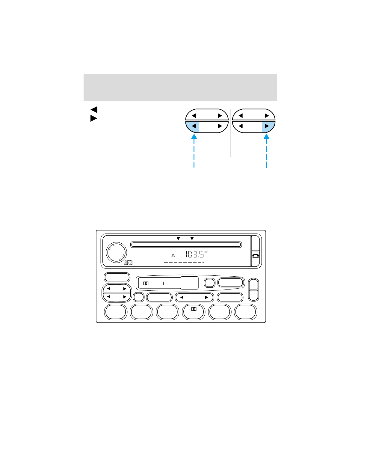
• to decrease minutes and
• to increase minutes.
SEEK
TUNE
SEEK
TUNE
The CLK control will allow you to switch between media display mode
(radio station, stereo information, etc.) and clock display mode (time).
When in clock mode, the media information will display for 10 seconds,
when the radio is turned on, and then revert to clock information.
Anytime that the media is changed, (new radio station, etc.), the media
information will again display for 10 seconds before reverting back to the
clock. In media mode, the media information will always be displayed.
Premium AM/FM Stereo/Cassette/Single CD
VOL PUSH ON
AM FM
SEEK
TUNE
FM 1
AMC
BL RF
DOLBY B NR
SCAN
BASS TREB SEL BAL
DISC
ST
TAPE
EJ CD
FADE
EJ
MUTE
AUTO
CLK
REW FF
SIDE 1-2 COMP SHUFFLE
123456
37
Page 38
Controls and features
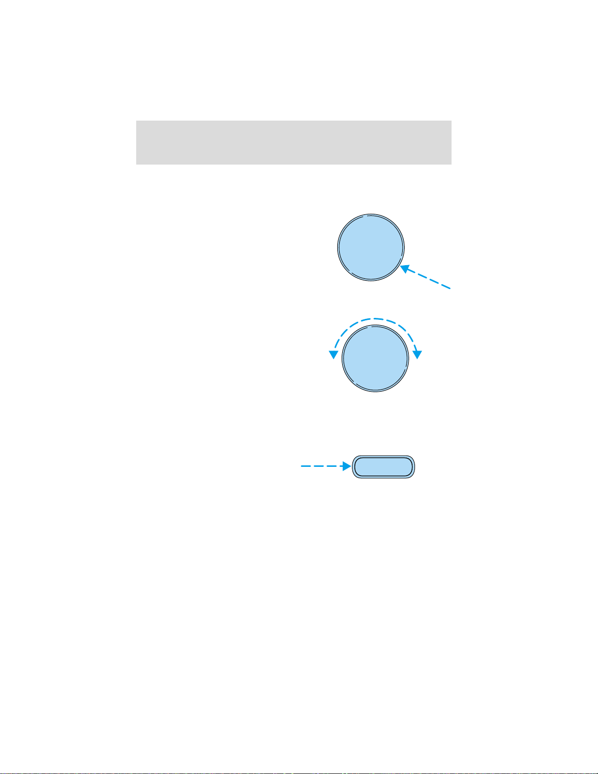
Volume/power control
Press the control to turn the audio
system on or off.
Audio power can also be turned on
by pressing the AM/FM select
control or the tape/CD select
control. Audio power is turned off
by using the volume/power control.
VOL
-
PUSH ON
Turn control to raise or lower
volume.
If the volume is set above a certain level and the ignition is turned off,
the volume will come back on at a “nominal” listening level when the
ignition switch is turned back on.
AM/FM select
The AM/FM select control works in
radio, tape and CD modes.
AM/FM select in radio mode
This control allows you to select AM or FM frequency bands. Press the
control to switch between AM, FM1 or FM2 memory preset stations.
AM/FM select in tape mode
Press this control to stop tape play and begin radio play.
Tune adjust
The tune control works in radio mode.
VOL
-
PUSH ON
AM FM
38
Page 39
Controls and features
Tune adjust in radio mode
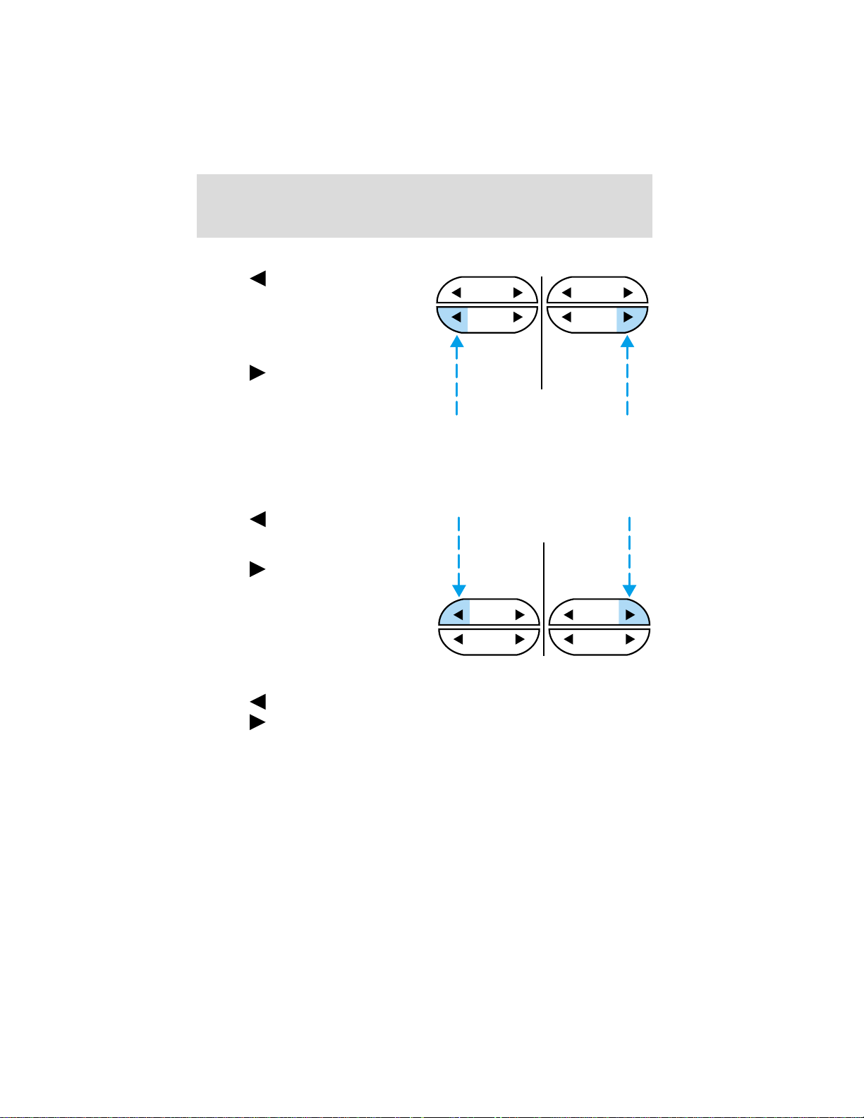
• Press to move to the next
frequency down the band
(whether or not a listenable
station is located there). Hold the
control to move through the
frequencies quickly.
• Press
to move to the next
frequency up the band (whether
or not a listenable station is
located there). Hold for quick
movement.
Seek function
The seek function control works in radio, tape or CD mode.
Seek function in radio mode
• Press
to find the next
listenable station down the
frequency band.
• Press
to find the next
listenable station up the
frequency band.
SEEK
TUNE
SEEK SEEK
SEEK
TUNE
Seek function in tape mode
• Press
• Press
to listen to the previous selection on the tape.
to listen to the next selection on the tape.
TUNE TUNE
39
Page 40
Controls and features
Seek function in CD mode
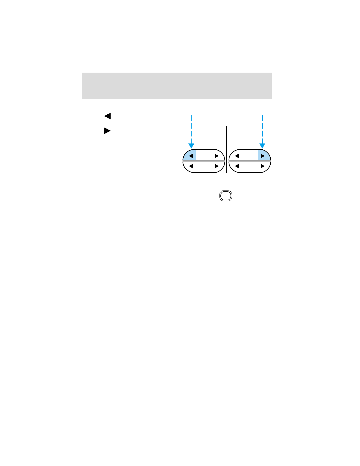
• Press to seek to the previous
track of the current disc.
• Press
next track of the current disc.
After the last track has been
completed, the first track of the
current disc will automatically
replay.
Scan function
The scan function works in radio,
tape or CD mode.
Scan function in radio mode
Press the SCAN control to hear a brief sampling of all listenable stations
on the frequency band. Press the control again to stop the scan mode.
Scan function in tape mode
Press the SCAN control to hear a short sampling of all selections on the
tape. (The tape scans in a forward direction. At the end of the tape’s
first side, direction automatically reverses to the opposite side of the
tape.) To stop on a particular selection, press the control again.
Scan function in CD mode
Press the SCAN control to hear a short sampling of all selections on the
CD. (The CD scans in a forward direction, wrapping back to the first
track at the end of the CD.) To stop on a particular selection, press the
control again.
Radio station memory preset
The radio is equipped with six station memory preset controls. These
controls can be used to select up to six preset AM stations and twelve
FM stations (six in FM1 and six in FM2).
to seek forward to the
SEEK SEEK
TUNE TUNE
SCAN
40
Page 41
Controls and features
Setting memory preset stations
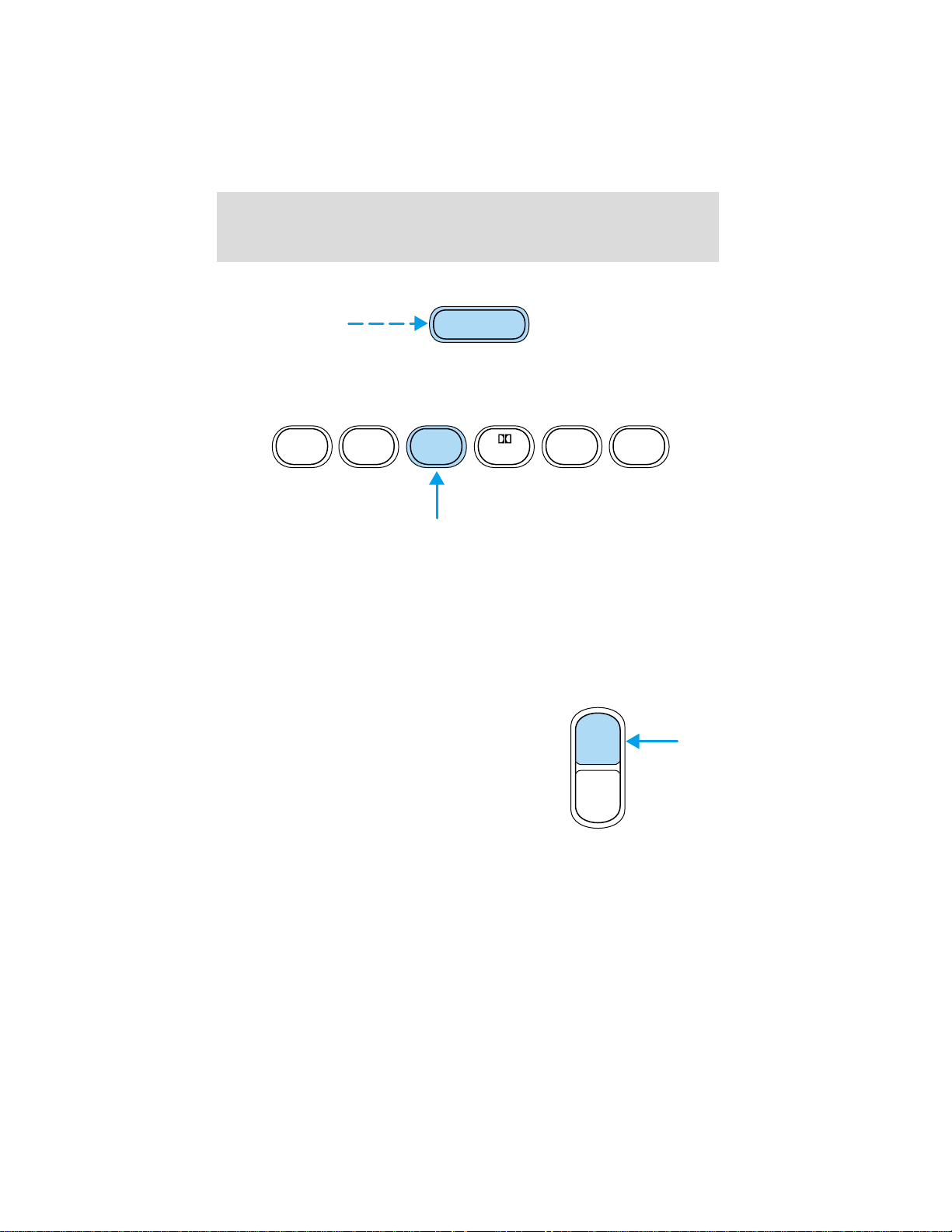
AM FM
1. Select the frequency band with the AM/FM select control.
2. Select a station. Refer to Tune adjust or Seek function for more
information on selecting a station.
REW FF SIDE 1-2 COMP SHUFFLE
123456
3. Press and hold a memory preset control until the sound returns,
indicating the station is held in memory on the control you selected.
Autoset memory preset
Autoset allows you to set strong radio stations without losing your
original manually set preset stations. This feature is helpful on trips
when you travel between cities with different radio stations.
Starting autoset memory preset
1. Select a frequency using the AM/FM select controls.
2. Press the AUTO control.
3. When the first six strong stations
are filled, the station stored in
memory preset control 1 will start
playing.
If there are less than six strong
stations available on the frequency
band, the remaining memory preset
controls will all store the last strong station available.
These stations are temporarily stored in the memory preset controls
(until deactivated) and are accessed in the same manner of your original
presets.
To deactivate autoset and return to your audio system’s manually set
memory stations, press the AUTO control again.
AUTO
CLK
41
Page 42
Controls and features
Bass adjust
The bass adjust control allows you
to increase or decrease the audio
system’s bass output.
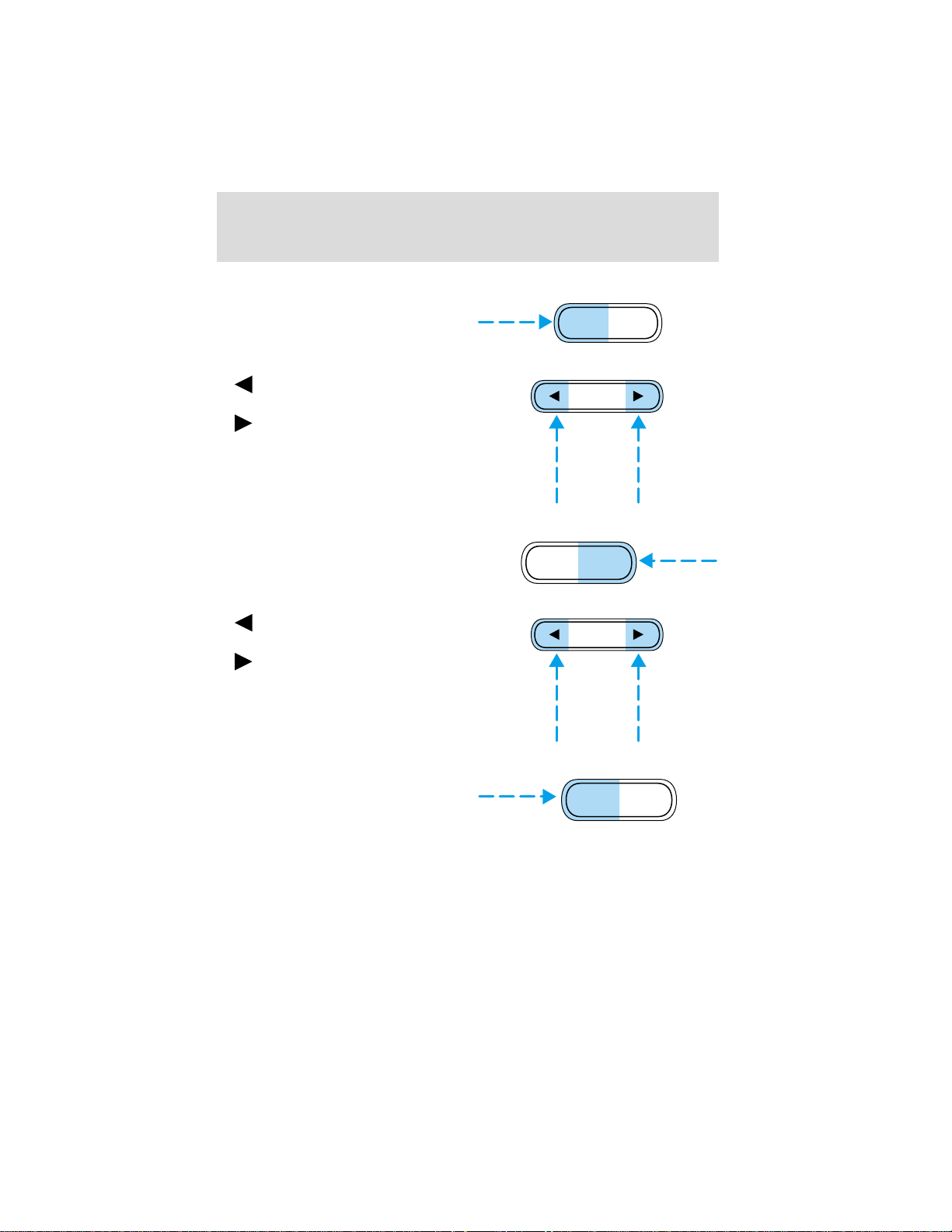
Press the BASS control then press:
•
•
Treble adjust
The treble adjust control allows you
to increase or decrease the audio
system’s treble output.
Press the TREB control then press:
•
•
to decrease the bass output
and
to increase the bass output.
to decrease the treble output
and
to increase the treble output.
BASS TREB
SEL
BASS TREB
SEL
Speaker balance adjust
Speaker sound distribution can be
adjusted between the right and left
speakers.
42
BAL FADE
Page 43
Controls and features
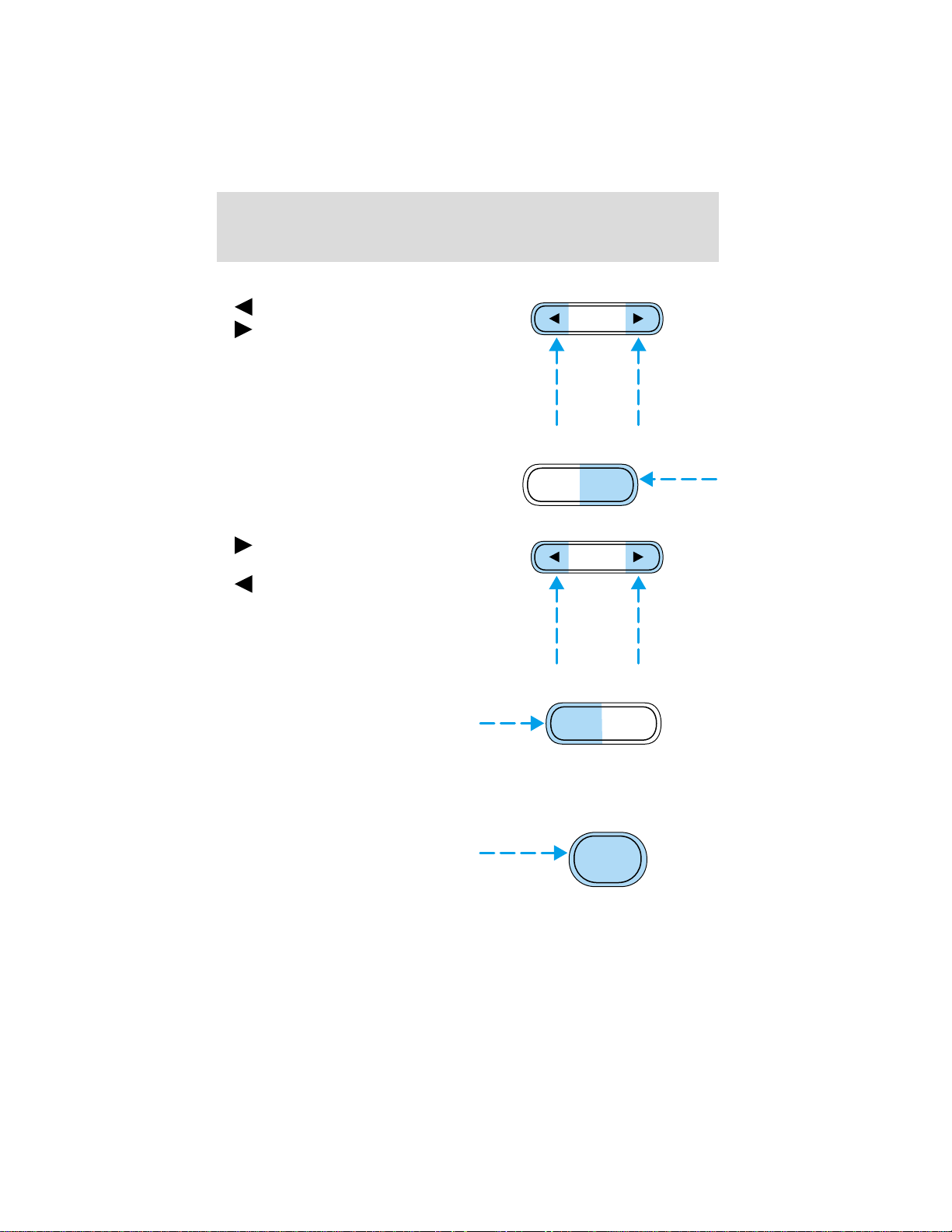
Press the BAL control then press:
• to shift sound to the left and
•
Speaker fade adjust
Speaker sound can be adjusted
between the front and rear
speakers.
Press the FADE control then press:
•
•
Tape select
• To begin tape play (with a tape
Rewind
The rewind control works in tape
and CD modes.
• In tape mode, radio play will
• In CD mode, pressing the REW control rewinds the CD within the
to shift sound to the right.
BAL FADE
to shift the sound to the
front and
to shift the sound to the rear.
loaded into the audio system)
while in the radio or CD mode,
press the TAPE control. Press the
button during rewind or fast forward to stop the rewind or fast
forward function.
continue until rewind is stopped
(with the TAPE control) or the beginning of the tape is reached.
current track.
SEL
SEL
TAPE CD
REW
1
43
Page 44
Controls and features
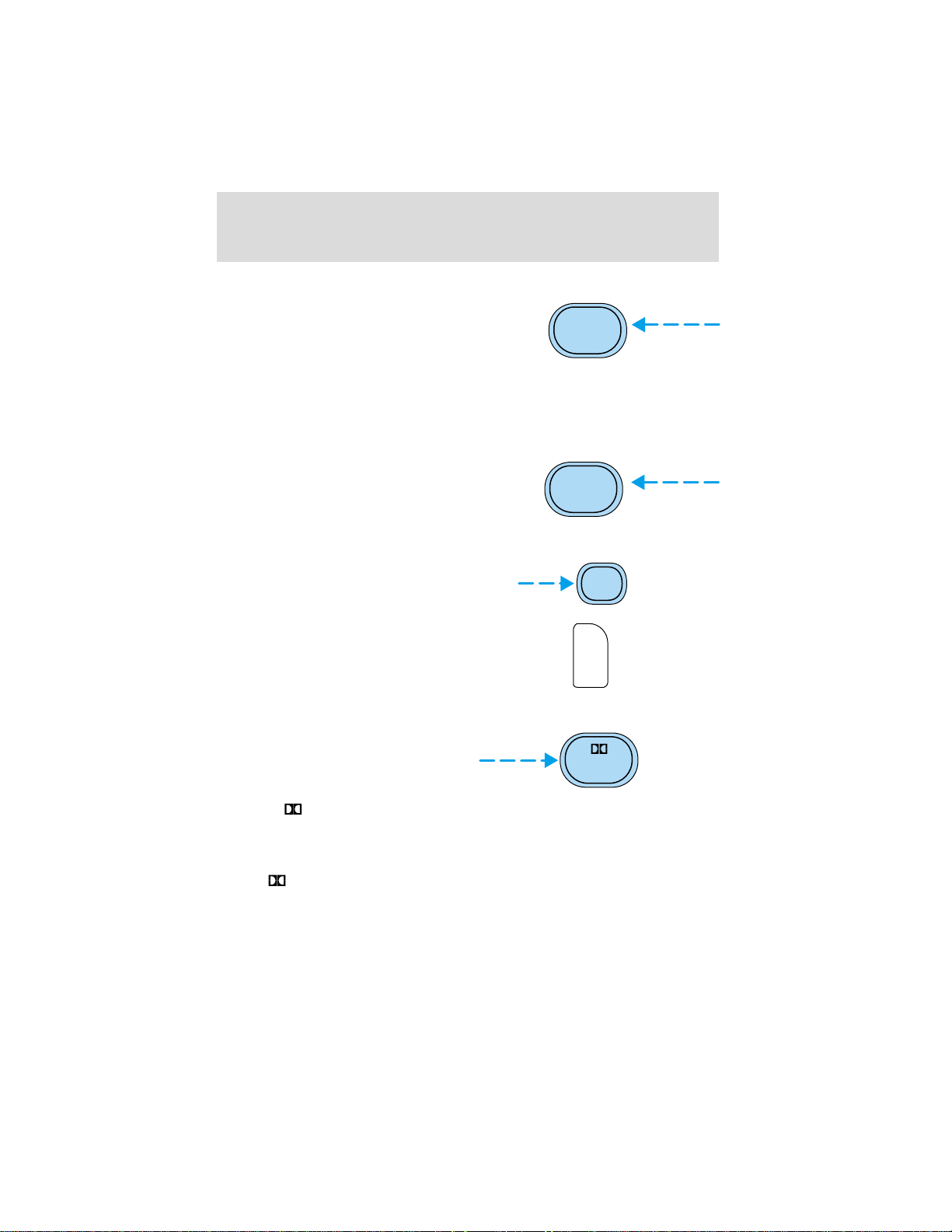
Fast forward
The fast forward control works in
tape and CD modes.
• In the tape mode, tape direction
will automatically reverse when
the end of the tape is reached.
• In CD mode, pressing the control fast forwards the CD within the
current track.
Tape direction select
Press SIDE 1–2 to play the alternate
side of a tape.
FF
2
SIDE 1-2
3
Eject function
Press the EJ control to stop and
eject a tape.
Press the EJ control to stop and
eject a CD.
EJ
EJ
Dolby姞 noise reduction
Dolby威 noise reduction operates in
tape mode. Dolby威 noise reduction
reduces the amount of hiss and
static during tape playback.
Press the
reduction.
Dolby威 noise reduction is manufactured under license from Dolby威
Laboratories Licensing Corporation. “Dolby威” and the double-D
symbol
Corporation.
44
control to activate (and deactivate) the Dolby威 noise
are trademarks of Dolby威 Laboratories Licensing
4
Page 45
Controls and features
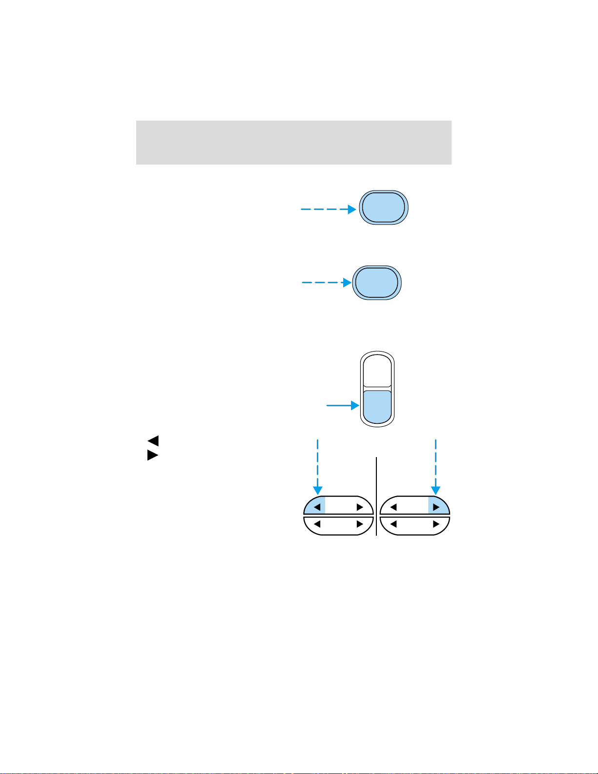
Compression adjust
Compression adjust brings soft and
loud CD passages together for a
more consistent listening level.
Press the COMP control to activate
and deactivate compression adjust.
Shuffle feature
The shuffle feature operates in CD
mode and plays all tracks on the
current disc in random order.
Press the SHUFFLE control to start
this feature. Random order play will continue until the SHUFFLE control
is pressed again.
Setting the clock
To set the hour, press and hold the
CLK control and press SEEK:
COMP
5
SHUFFLE
6
AUTO
CLK
•
• to increase hours.
to decrease hours and
SEEK SEEK
TUNE TUNE
45
Page 46
Controls and features
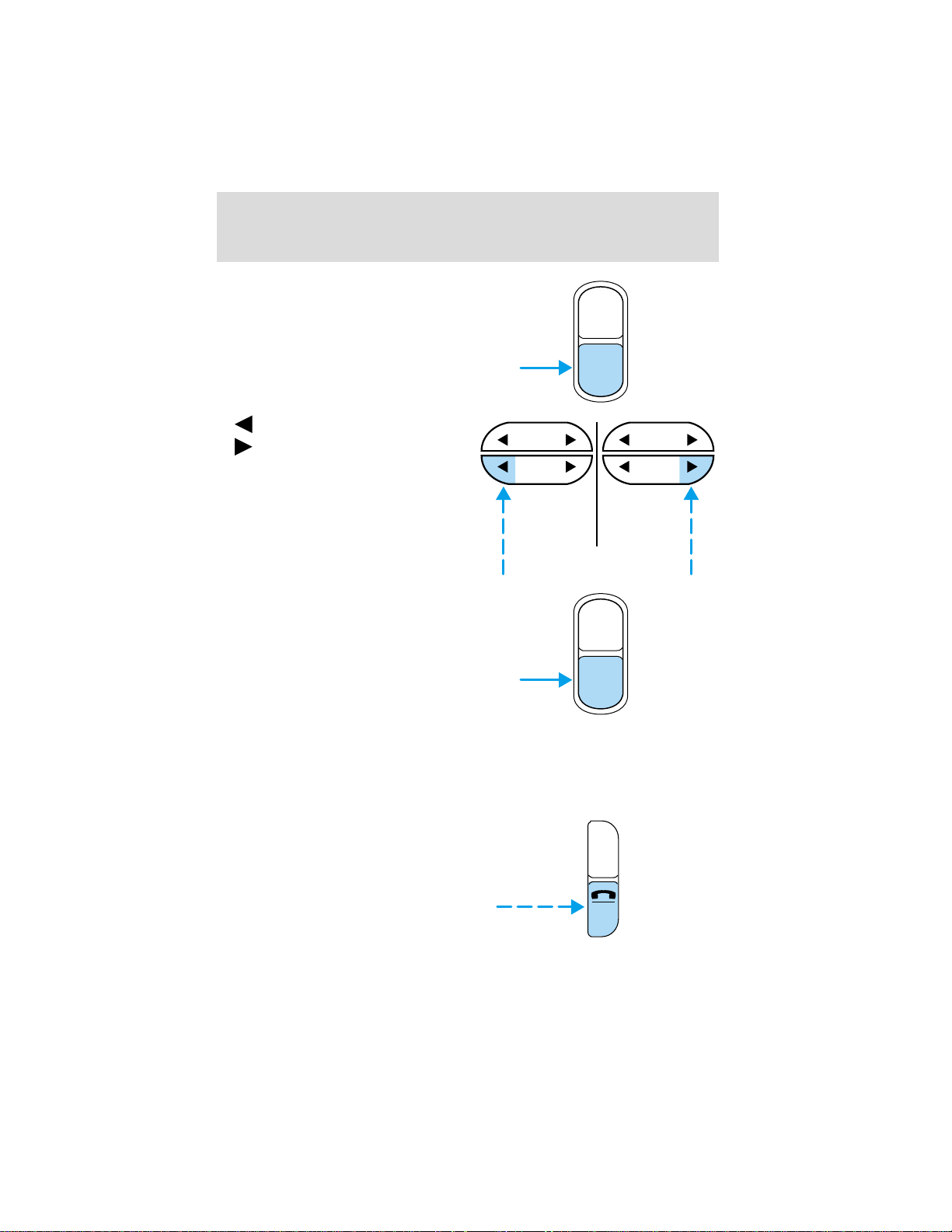
To set the minute, press and hold
the CLK control and press TUNE:
AUTO
CLK
•
•
If your vehicle has a separate clock
module, (other than the digital radio
display), the CLK button will not
function in the above manner.
The CLK button will allow you to
switch between media display mode
(radio station, stereo information,
etc.) and clock display mode (time).
When in clock mode, the media
information will display for 10
seconds, when the radio is turned
on, and then revert to clock
information. Anytime that the media
is changed, (new radio station, etc.), the media information will again
display for 10 seconds before reverting back to the clock. In media mode,
the media information will always be displayed.
Mute mode
Press the control to mute the
playing media. Press the control
again to return to the playing media.
to decrease minutes and
to increase minutes.
SEEK
TUNE
SEEK
TUNE
AUTO
CLK
EJ
46
MUTE
Page 47

Controls and features
Troubleshooting the CD player
The laser beam used in the compact disc player is harmful to the
eyes. Do not attempt to disassemble the case.
If sound skips:
• You may be traveling on a rough road, playing badly scratched discs or
the disc may be dirty. Skipping will not scratch the discs or damage
the player.
If player does not work:
• The disc is inserted with the label surface downward.
• The disc is dusty or defective.
• A disc with format and dimensions not within industry standards is
inserted.
Cleaning compact discs
Inspect all discs for contamination before playing. If necessary, clean
discs only with an approved CD cleaner and wipe the center out to the
edge. Do not use circular motion.
CD and CD player care
• Handle discs by their edges only. Never touch the playing surface.
• Do not insert more than one disc at a time.
• Do not expose discs to direct sunlight or heat sources for extended
periods of time.
• After playing, store the disc in its case.
Cleaning cassette player (if equipped)
Clean the tape player head with a cassette cleaning cartridge after 10 to
12 hours of play in order to maintain the best sound and operation.
Cassette and cassette player care
• Use only cassettes that are 90 minutes long or less.
• Do not expose tapes to direct sunlight, high humidity, extreme heat or
extreme cold. Allow tapes that may have been exposed to extreme
temperatures to reach a moderate temperature before playing.
47
Page 48

Controls and features
• Tighten very loose tapes by inserting a finger or pencil into the hole
and turning the hub.
• Remove loose labels before inserting tapes.
• Do not leave tapes in the cassette player for a long time when not
being played.
Radio frequency information
The Federal Communications Commission (FCC) and the Canadian Radio
and Telecommunications Commission(CRTC) establish the frequencies
AM and FM stations may use for their broadcasts. Allowable frequencies
are:
AM 530, 540–1600, 1610 kHz
FM 87.7, 87.9–107.7, 107.9 MHz
Not all frequencies are used in a given area.
Radio reception factors
Three factors can affect radio reception:
• Distance/strength. The further an FM signal travels, the weaker it is.
The listenable range of the average FM station is approximately 40 km
(24 miles). This range can be affected by “signal modulation.” Signal
modulation is a process radio stations use to increase their
strength/volume relative to other stations.
• Terrain. Hills, mountains and tall buildings between your vehicle’s
antenna and the radio station signal can cause FM reception problems.
Static can be caused on AM stations by power lines, electric fences,
traffic lights and thunderstorms. Moving away from an interfering
structure (out of its “shadow”) returns your reception to normal.
• Station overload. Weak signals are sometimes captured by stronger
signals when you pass a broadcast tower. A stronger signal may
temporarily overtake a weaker signal and play while the weak station
frequency is displayed.
The audio system automatically switches to single channel reception if it
will improve the reception of a station normally received in stereo.
Audio system warranties and service
Refer to the “Warranty Guide” for audio system warranty information.
If service is necessary, see your dealer or a qualified technician.
48
Page 49
Controls and features
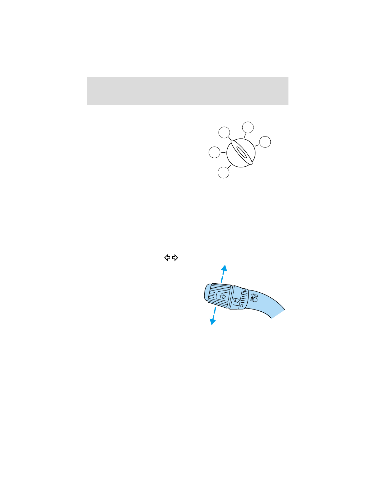
POSITIONS OF THE IGNITION
1. ACCESSORY, allows the electrical
accessories such as the radio to
operate while the engine is not
running.
2. LOCK, locks the steering wheel,
automatic transmission gearshift
lever and allows key removal.
3. OFF, shuts off the engine and all
accessories without locking the
steering wheel.
4. ON, all electrical circuits operational. Warning lights illuminated. Key
position when driving.
5. START, cranks the engine. Release the key as soon as the engine
starts.
HAZARD FLASHER
For information on the hazard flasher control, refer to Hazard flasher in
the Roadside emergencies chapter.
TURN SIGNAL CONTROL
• Push down to activate the left
turn signal.
• Push up to activate the right turn
signal.
3
2
1
4
5
49
Page 50
Controls and features
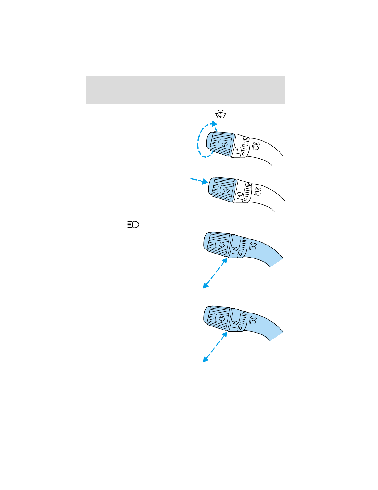
WINDSHIELD WIPER/WASHER CONTROLS
Rotate the windshield wiper control
to the desired interval, low or high
speed position.
The bars of varying length are for
intermittent wipers. When in this
position rotate the control upward
for fast intervals and downward for
slow intervals.
Push the control on the end of the
stalk to activate washer. Push and
hold for a longer wash cycle. The
washer will automatically shut off
after ten seconds of continuous use.
HIGH BEAMS
Push forward to activate.
Pull toward you to deactivate.
FLASH TO PASS
Pull toward you to activate and
release to deactivate.
50
Page 51
SPEED CONTROL (IF EQUIPPED)
To turn speed control on
• Press ON.
Vehicle speed cannot be controlled
until the vehicle is traveling at or
above 48 km/h (30 mph).
Do not use the speed control in heavy traffic or on roads that
are winding, slippery, or unpaved.
Do not shift the gearshift lever into N (Neutral) with the speed
control on.
To turn speed control off
• Press OFF or
• Turn off the vehicle ignition.
Controls and features
ON
OFF
ON
OFF
Once speed control is switched off, the previously programmed set speed
will be erased.
51
Page 52
Controls and features
To set a speed
• Press SET ACCEL. For speed
control to operate, the speed
control must be ON and the
vehicle speed must be greater
than 48 km/h (30 mph).
If you drive up or down a steep hill, your vehicle speed may vary
momentarily slower or faster than the set speed. This is normal.
Speed control cannot reduce the vehicle speed if it increases above the
set speed on a downhill. If your vehicle speed is faster than the set
speed while driving on a downhill, you may want to shift to the next
lower gear or apply the brakes to reduce your vehicle speed.
If your vehicle slows down more than 16 km/h (10 mph) below your set
speed on an uphill, your speed control will disengage. This is normal.
Pressing RES will re-engage it.
Do not use the speed control in heavy traffic or on roads that
are winding, slippery, or unpaved.
RES
SET
ACCEL
C
O
A
S
T
To set a higher set speed
• Press and hold SET ACCEL.
Release the control when the
desired vehicle speed is reached
or
• Press and release SET ACCEL.
Each press will increase the set
speed by 1.6 km/h (1 mph) or
• Accelerate with your accelerator
pedal. When the desired vehicle
speed is reached, press and
release SET ACCEL.
52
RES
SET
ACCEL
C
O
A
S
T
Page 53
Controls and features
You can accelerate with the accelerator pedal at any time during speed
control usage. Releasing the accelerator pedal will return your vehicle to
the previously programmed set speed.
To set a lower set speed
• Press and hold COAST. Release
the control when the desired
speed is reached or
• Press and release COAST. Each
press will decrease the set speed
by 1.6 km/h (1 mph) or
• Depress the brake pedal. When
the desired vehicle speed is
reached, press SET ACCEL.
RES
SET
ACCEL
C
O
A
RES
SET
ACCEL
C
O
A
S
T
S
T
53
Page 54
Controls and features
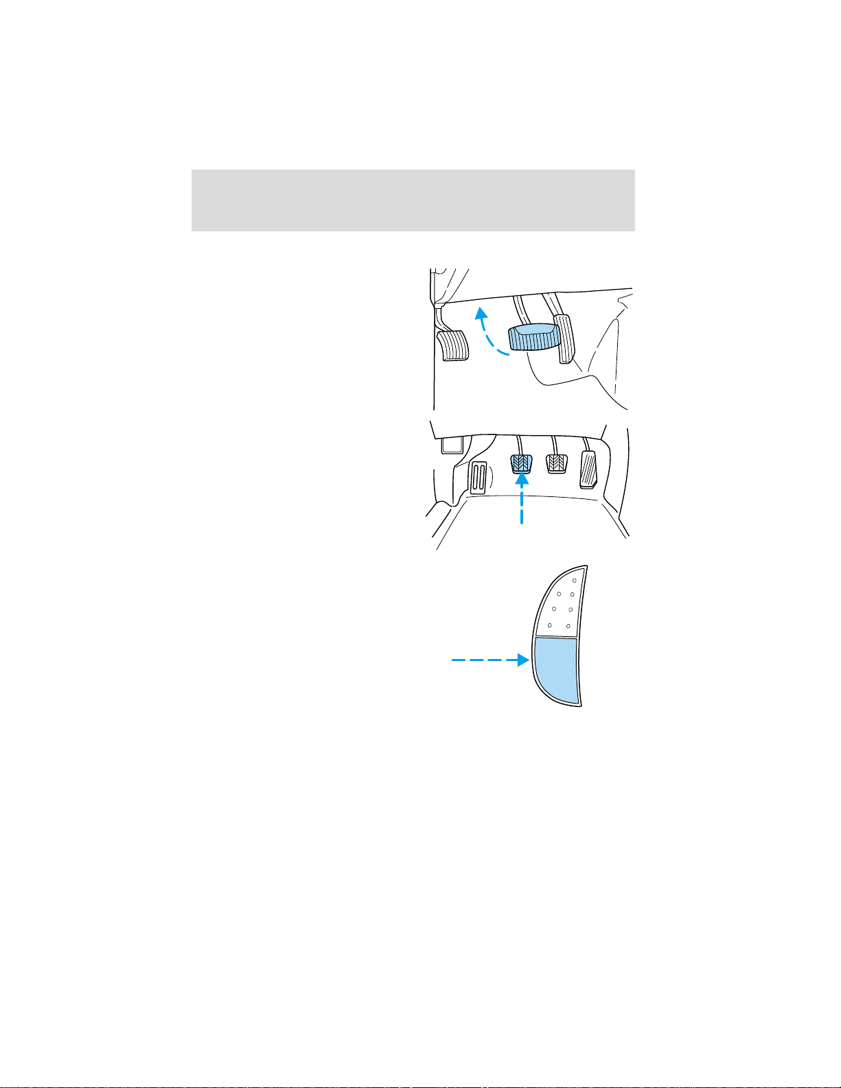
To disengage speed control
• Depress the brake pedal or
• Depress the clutch pedal (if
equipped).
Disengaging the speed control will
not erase the previously
programmed set speed.
Pressing OFF will erase the
previously programmed set speed.
ON
54
OFF
Page 55
Controls and features
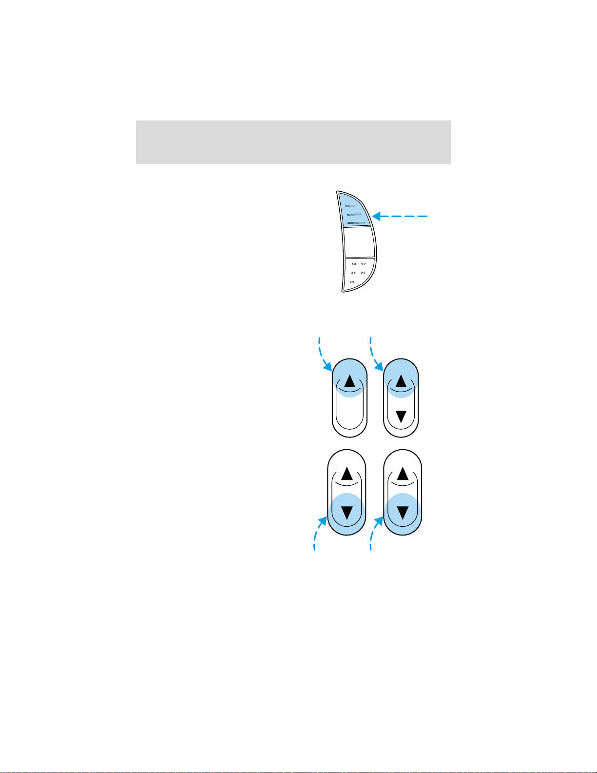
To return to a previously set speed
• Press RES. For RES to operate,
the vehicle speed must be faster
than 48 km/h (30 mph).
POWER WINDOWS (IF EQUIPPED)
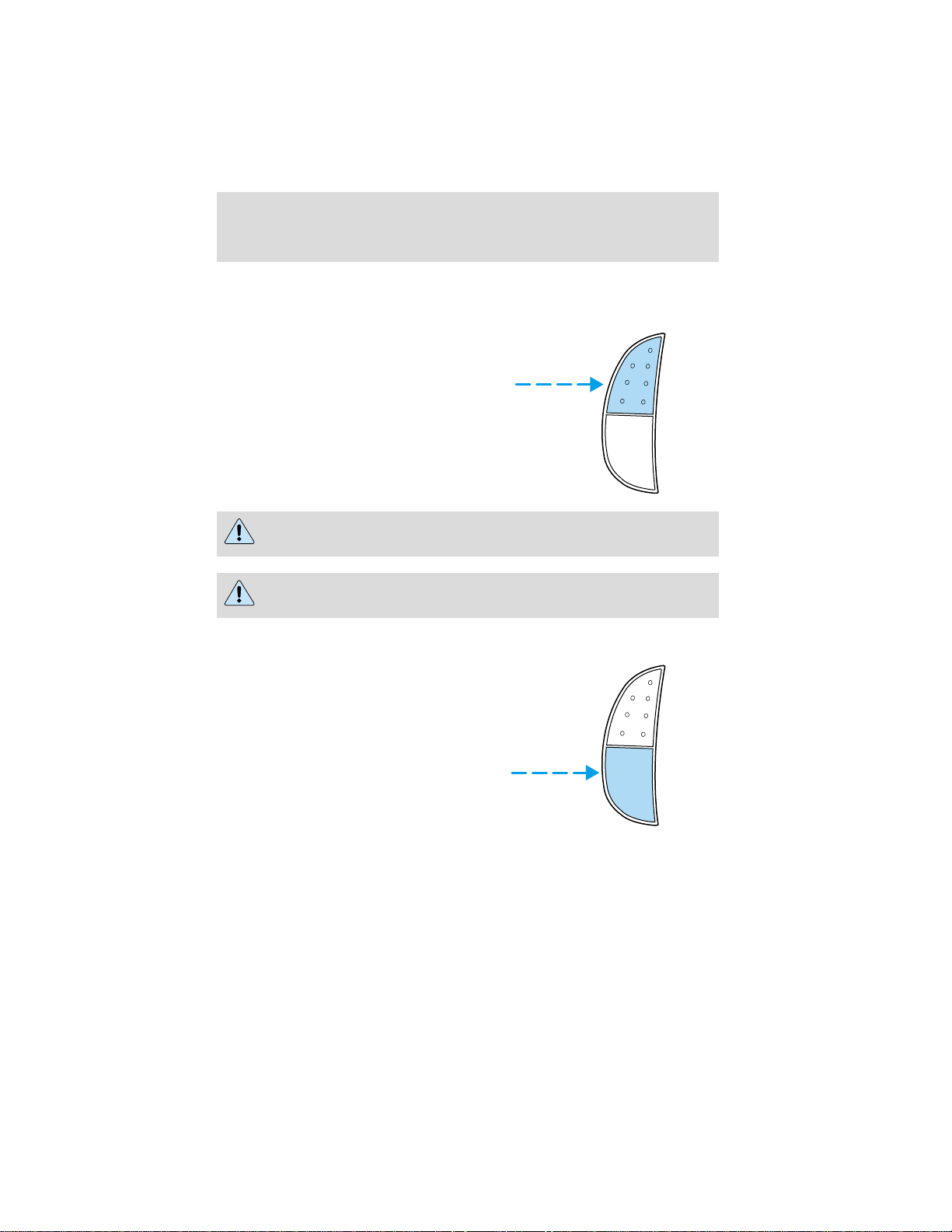
Press and hold the rocker switches to open and close windows.
• Press the top portion of the
rocker switch to close.
RES
SET
ACCEL
C
O
AUTO
A
S
T
• Press the bottom portion of the
rocker switch to open.
55
Page 56
Controls and features
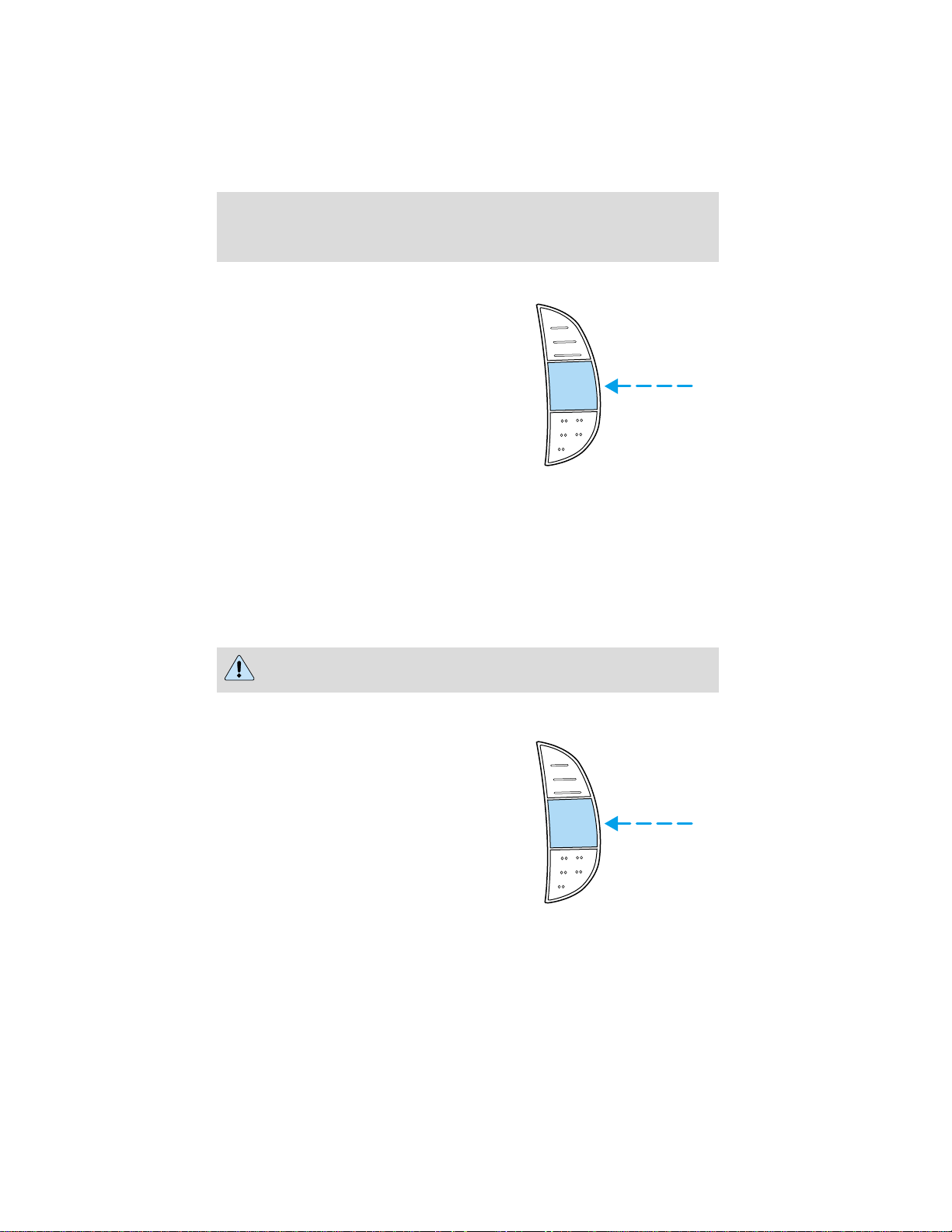
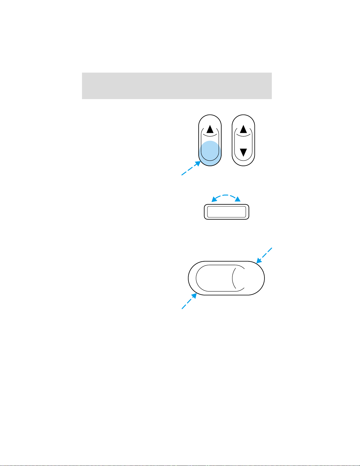
One touch down
• Press AUTO completely down and
release quickly. The driver’s
window will open fully. Depress
again to stop window operation.
AUTO
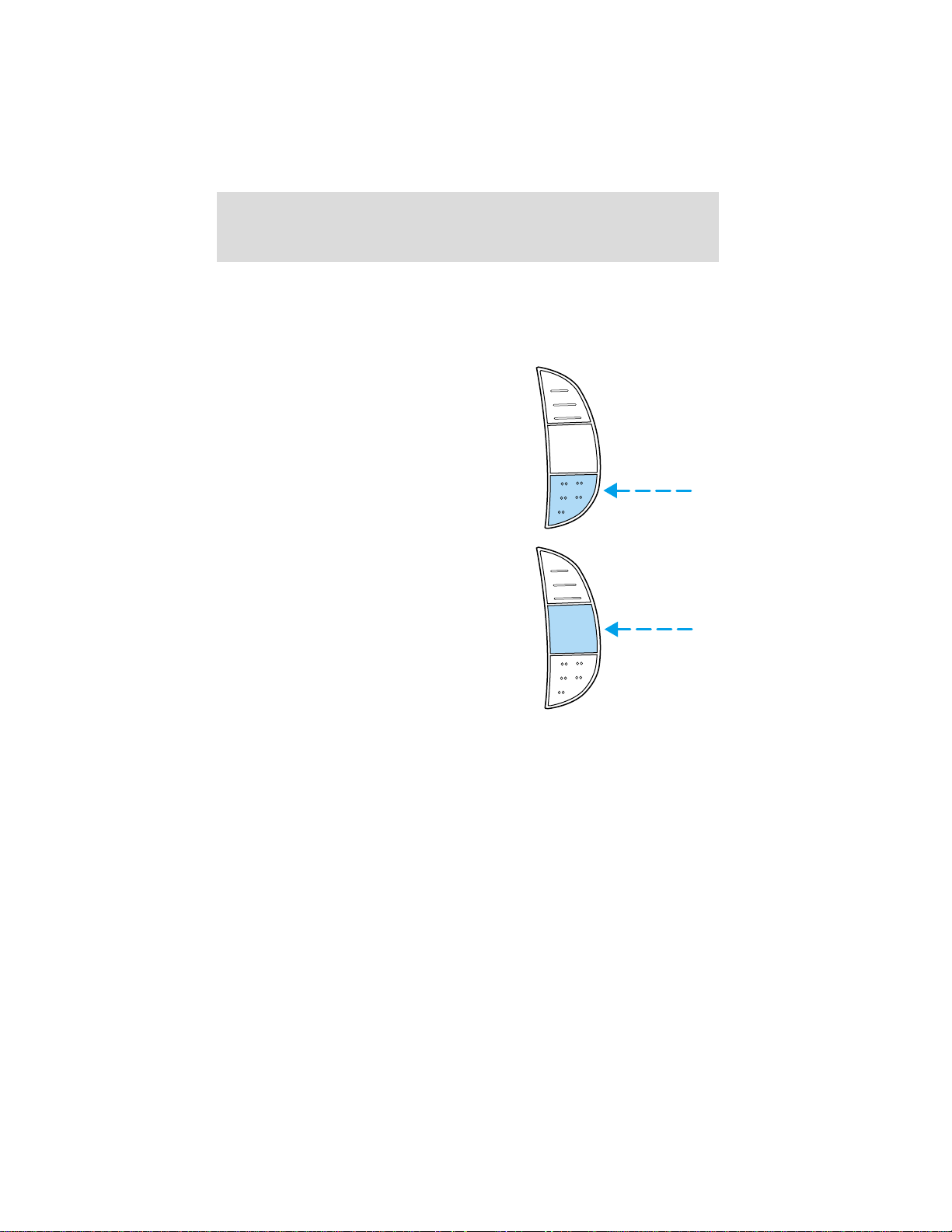
Window lock (if equipped)
The window lock feature allows only
the driver to operate the power
windows.
To lock out all the window controls
except for the driver’s press the left
side of the control. Press the right side to restore the window controls.
POWER DOOR LOCKS (IF EQUIPPED)
Press U to unlock all doors and L to
lock all doors.
56
UL
Page 57
MIRRORS
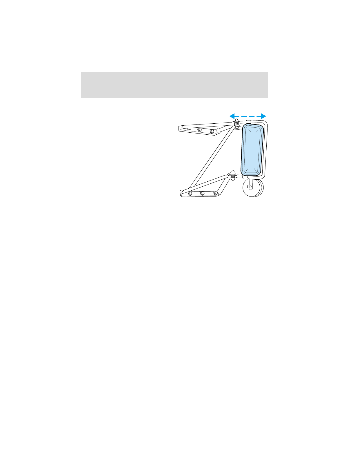
With the doors closed and the seat
adjusted for proper comfort, move
the mirrors to maximize rear
viewing area by adjusting the
western mirrors left or right as
required.
Adjust the auxiliary convex mirrors.
Convex mirrors are a ball-stud
design for precise adjustment to
maximize viewing area.
Controls and features
57
Page 58
Seating and safety restraints
SEATING
Driver’s seat adjustment
Never adjust the driver’s seat or seatback when the vehicle is
moving.
Always drive and ride with your seatback upright and the lap
belt snug and low across the hips.
Reclining the seatback can reduce the effectiveness of the seat’s
safety belt in the event of a collision.
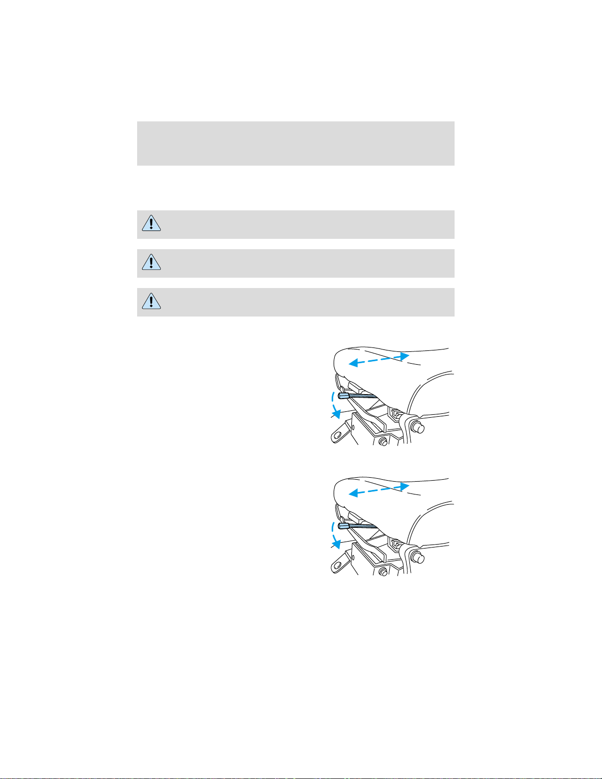
Fixed-back seat
Move handle to the left to move seat
forward or backward.
Recline seat (if equipped)
Move handle to the left to move seat
forward or backward.
58
Page 59
Seating and safety restraints
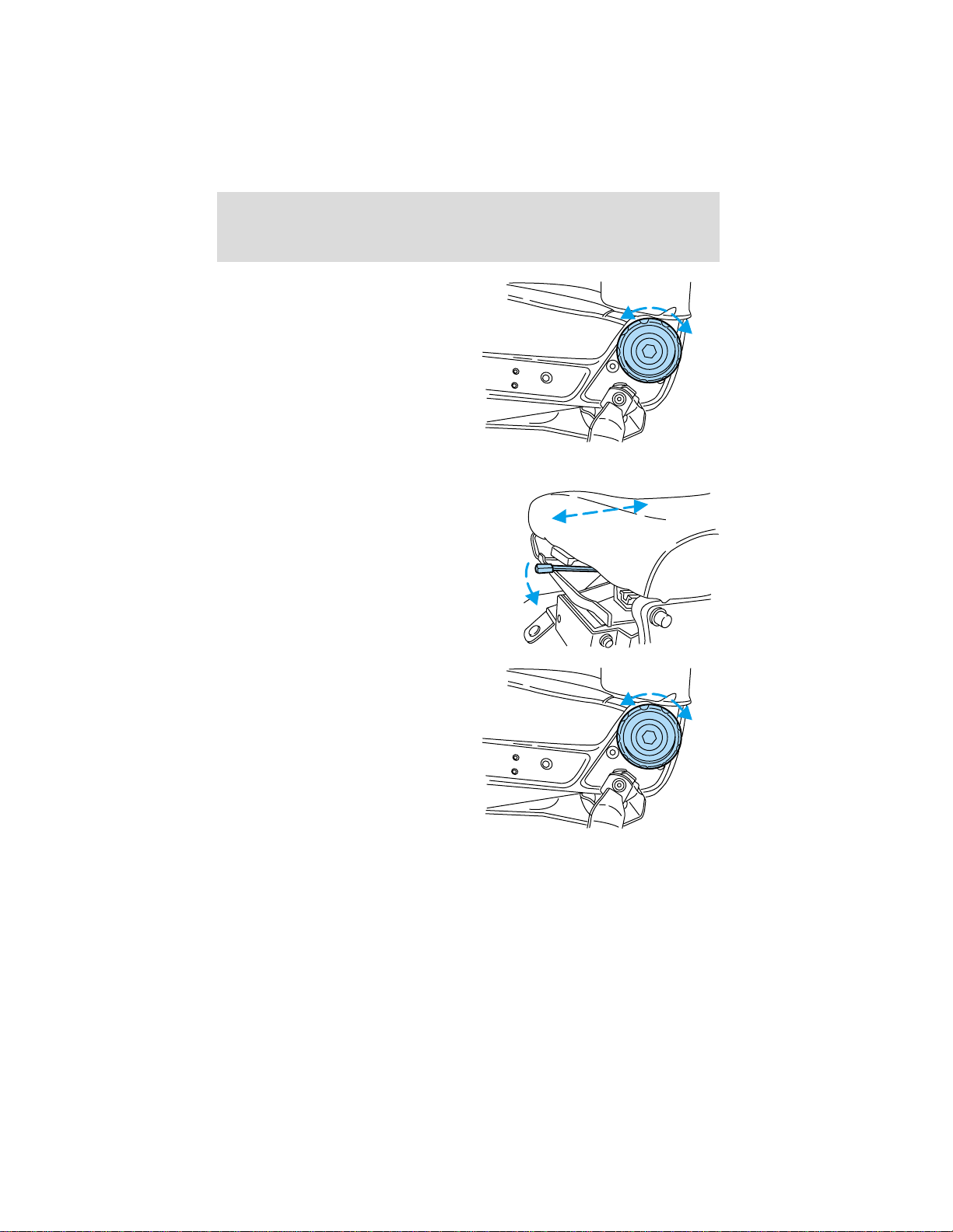
Rotate control to adjust seatback.
Easy-Aire seat (if equipped)
Move handle to the left to move seat
forward or backward.
Rotate control to adjust seatback.
59
Page 60
Seating and safety restraints
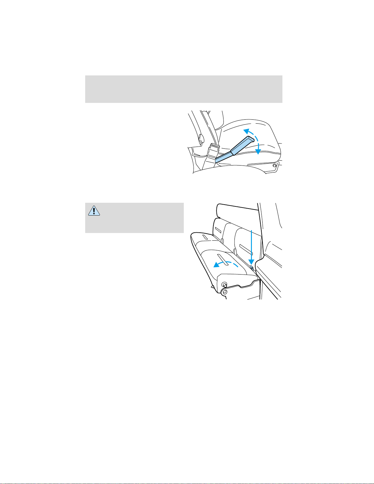
Pump handle to raise seat height.
Push handle full down to lower.
Always adjust the seat height
before fastening seatbelt.
Rear folding bench seat (if equipped)
Folding down the rear seats
All safety belts should be
properly stowed in the seat
pockets before folding down the
rear seat.
Make sure that no objects such as
books, purses or briefcases are on
the floor in front of the second row
seats before folding them down.
1. Locate the strap on the rear of
the lower seat cushion.
2. Lift the strap and rotate the lower
seat cushion toward the front of the
vehicle.
60
Page 61
Seating and safety restraints
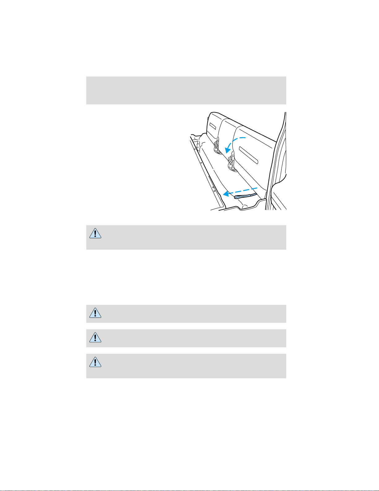
3. Locate the strap below the
seatback.
4. Pull downward on the strap to
release the seatback.
5. Rotate the seatback forward.
Returning the seat to upright
Always latch the vehicle seat to the floor, whether the seat is
occupied or empty. If not latched, the seat may cause injury
during a sudden stop.
1. Lift/rotate the seatback toward the rear of the vehicle and make sure
it latches securely.
2. Lift/rotate the lower seat cushion to its seating position.
SAFETY RESTRAINTS
Safety restraints precautions
Always drive and ride with your seatback upright and the lap
belt snug and low across the hips.
To reduce the risk of injury, make sure children sit where they
can be properly restrained.
Never let a passenger hold a child on his or her lap while the
vehicle is moving. The passenger cannot protect the child from
injury in a collision.
61
Page 62
Seating and safety restraints
All occupants of the vehicle, including the driver, should always
properly wear their safety belts, even when an air bag SRS is
provided.
It is extremely dangerous to ride in a cargo area, inside or
outside of a vehicle. In a collision, people riding in these areas
are more likely to be seriously injured or killed. Do not allow people to
ride in any area of your vehicle that is not equipped with seats and
safety belts. Be sure everyone in your vehicle is in a seat and using a
safety belt properly.
In a rollover crash, an unbelted person is significantly more likely
to die than a person wearing a seat belt.
Each seating position in your vehicle has a specific safety belt
assembly which is made up of one buckle and one tongue that
are designed to be used as a pair. 1) Use the shoulder belt on the
outside shoulder only. Never wear the shoulder belt under the arm.
2) Never swing the safety belt around your neck over the inside
shoulder. 3) Never use a single belt for more than one person.
Always transport children 12 years old and under in the back
seat and always properly use appropriate child restraints.
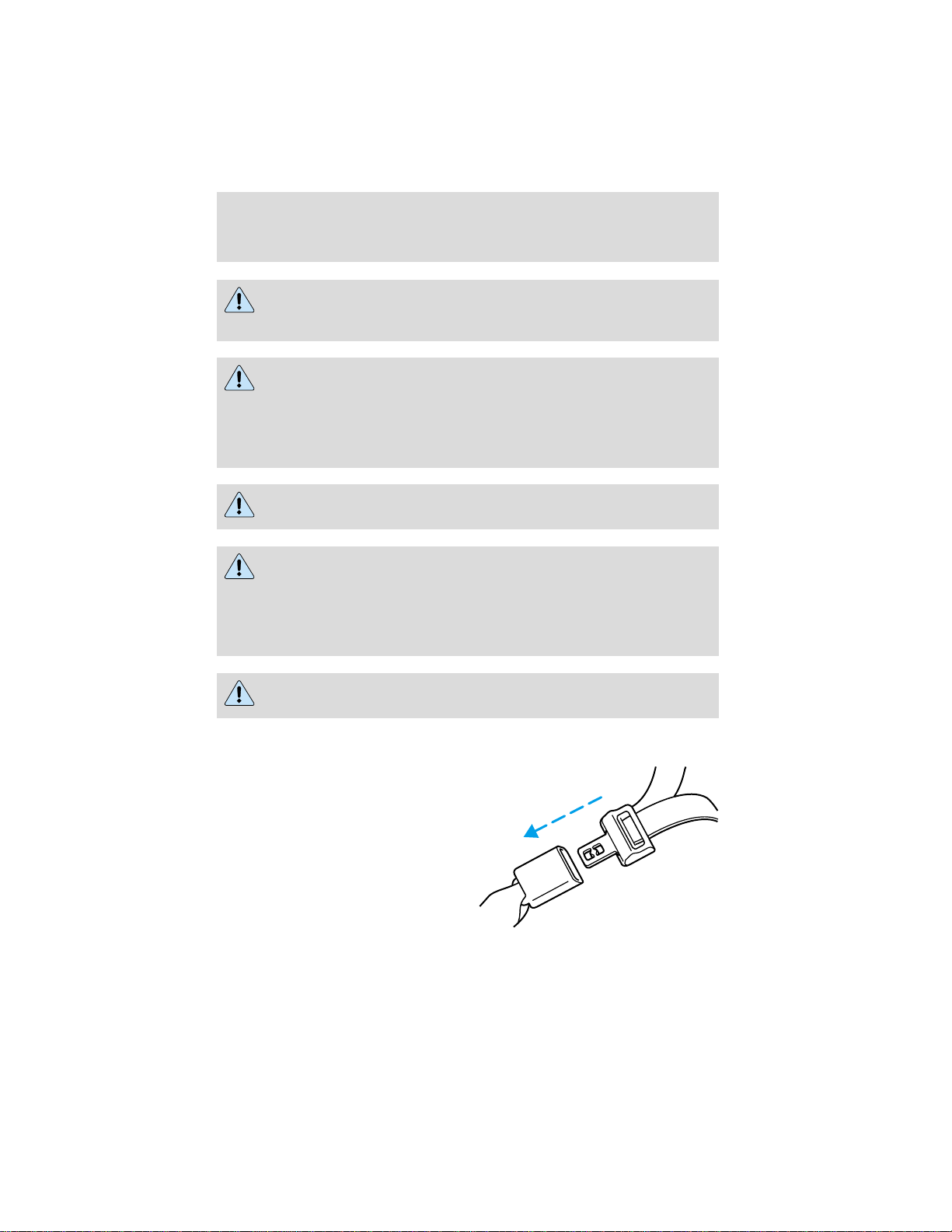
Combination lap and shoulder belts
1. Insert the belt tongue into the
proper buckle (the buckle closest to
the direction the tongue is coming
from) until you hear a snap and feel
it latch. Make sure the tongue is
securely fastened in the buckle.
62
Page 63
Seating and safety restraints
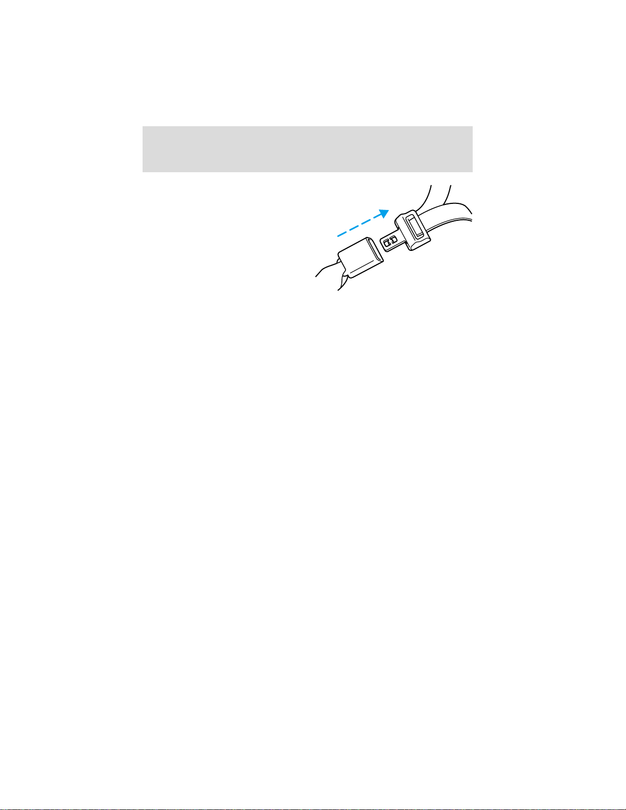
2. To unfasten, push the release
button and remove the tongue from
the buckle.
The front and rear outboard safety restraints in the vehicle are
combination lap and shoulder belts. The front and rear seat passenger
outboard safety belts have vehicle sensitive emergency locking retractors.
Vehicle sensitive retractor
The vehicle sensitive retractor allows free shoulder belt length
adjustment to your movements and locks in response to vehicle
movement. For example, if the driver brakes suddenly or turns a corner
sharply, or the vehicle receives an impact of approximately 8 km/h (5
mph) or more, the combination safety belts will lock to help reduce
forward movement of the driver and passengers.
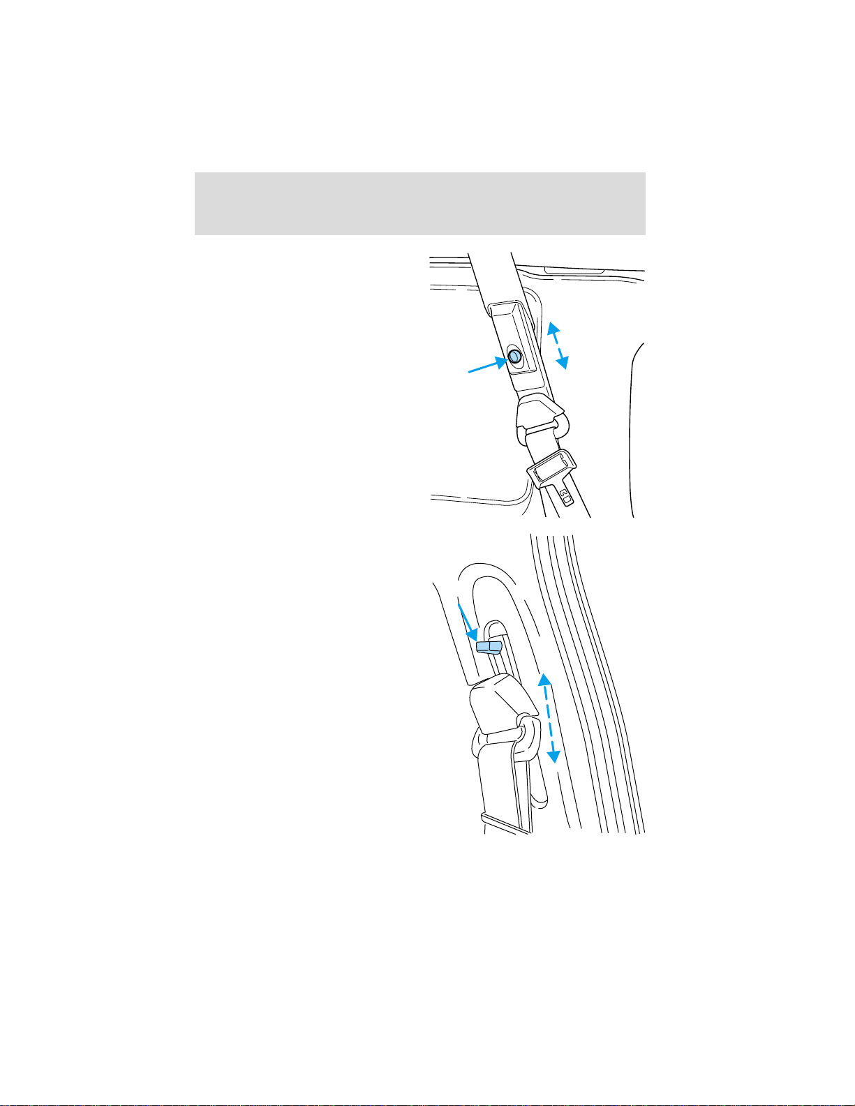
Front safety belt height adjustment
SuperCab and CrewCab vehicle has safety belt height adjustments for
the driver and front passenger. Adjust the height of the shoulder belt so
the belt rests across the middle of your shoulder.
63
Page 64
Seating and safety restraints
• 4–door SuperCab
• 4–door CrewCab
64
Page 65
Seating and safety restraints
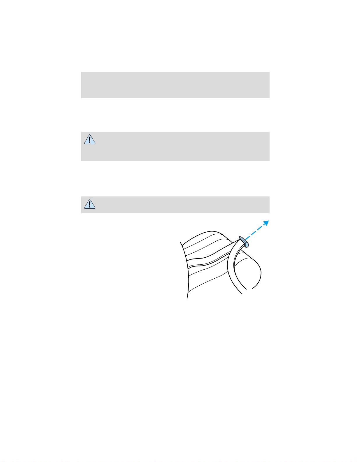
To lower the shoulder belt height, push the button and slide the height
adjuster down. To raise the height of the shoulder belt, slide the height
adjuster up. Pull down on the height adjuster to make sure it is locked in
place.
Position the shoulder belt height adjusters so that the belt rests
across the middle of your shoulder. Failure to adjust the safety
belt properly could reduce the effectiveness of the seat belt and
increase the risk of injury in a collision.
Lap belts
Adjusting the lap belt
The lap belt does not adjust automatically.
The lap belts should fit snugly and as low as possible around the
hips, not around the waist.
Insert the tongue into the correct
buckle (the buckle closest to the
direction the tongue is coming
from). To lengthen the belt, turn the
tongue at a right angle to the belt
and pull across your lap until it
reaches the buckle. To tighten the
belt, pull the loose end of the belt
through the tongue until it fits
snugly across the hips.
65
Page 66
Seating and safety restraints
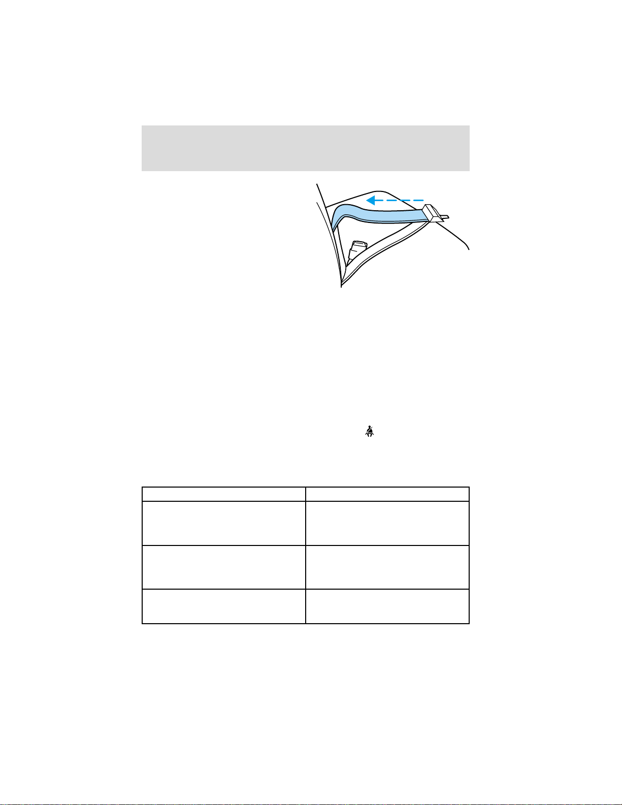
Shorten and fasten the belt when
not in use.
Safety belt extension assembly
If the safety belt assembly is too short, even when fully extended, 20 cm
(8 inches) can be added to the safety belt assembly by adding a safety
belt extension assembly (part number 611C22). Safety belt extension
assemblies can be obtained from your dealer at no cost.
Use only extensions manufactured by the same supplier as the safety
belt. Manufacturer identification is located at the end of the webbing on
the label. Also, use the safety belt extension only if the safety belt is too
short for you when fully extended. Do not use extensions to change the
fit of the shoulder belt across the torso.
Safety belt warning light and indicator chime
The seat belt warning light illuminates in the instrument cluster and a
chime sounds to remind the occupants to fasten their safety belts.
Conditions of operation
If... Then...
The driver’s safety belt is not
buckled before the ignition switch
is turned to the ON position...
The driver’s safety belt is buckled
while the indicator light is
illuminated and the warning chime
is sounding...
The driver’s safety belt is buckled
before the ignition switch is turned
to the ON position...
66
The safety belt warning light
illuminates1-2 minutes and the
warning chime sounds 4-8
seconds.
The safety belt warning light and
warning chime turn off.
The safety belt warning light and
indicator chime remain off.
Page 67

Seating and safety restraints
Belt minder (if equipped)
The Belt Minder feature is a supplemental warning to the safety belt
warning function. This feature provides additional reminders to the
driver that the driver’s safety belt is unbuckled by intermittently
sounding a chime and illuminating the safety belt warning lamp in the
instrument cluster.
If... Then...
The driver’s safety belt is not
buckled before the vehicle has
reached at least 5 km/h (3 mph)
and 1-2 minutes have elapsed
since the ignition switch has been
turned to ON...
The driver’s safety belt is buckled
while the safety belt indicator light
is illuminated and the safety belt
warning chime is sounding...
The driver’s safety belt is buckled
before the ignition switch is turned
to the ON position...
The purpose of the Belt Minder is to remind occasional wearers to wear
safety belts all of the time.
The Belt Minder feature is
activated - the safety belt warning
light illuminates and the warning
chime sounds for 6 seconds every
30 seconds, repeating for
approximately 5 minutes or until
safety belt is buckled.
The Belt Minder feature will not
activate.
The Belt Minder feature will not
activate.
67
Page 68
Seating and safety restraints
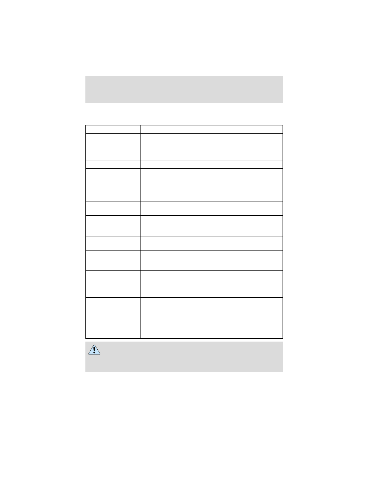
The following are reasons most often given for not wearing safety belts:
(All statistics based on U.S. data)
Reasons given... Consider...
⬙Crashes are rare
events⬙
⬙I’m not going far⬙ 3of4fatal crashes occur within 25 miles of home.
⬙Belts are
uncomfortable⬙
⬙I was in a hurry⬙ Prime time for an accident. Belt Minder reminds
⬙Seat belts don’t
work⬙
⬙Traffic is light⬙ Nearly 1 of 2 deaths occur in single-vehicle
⬙Belts wrinkle my
clothes⬙
⬙The people I’m
with don’t wear
belts⬙
⬙I have an air bag⬙ Air bags offer greater protection when used with
⬙I’d rather be
thrown clear⬙
36 700 crashes occur every day. The more we
drive, the more we are exposed to ⬙rare⬙ events,
even for good drivers. 1 in 4 of us will be seriously
injured in a crash during our lifetime.
Ford designs its safety belts to enhance comfort. If
you are uncomfortable - try different positions for
the safety belt upper anchorage and seatback
which should be as upright as possible; this can
improve comfort.
us to take a few seconds to buckle up.
Safety belts, when used properly, reduce risk of
death to front seat occupants by 45% in cars,
and by 60% in light trucks.
crashes, many when no other vehicles are around.
Possibly, but a serious crash can do much more
than wrinkle your clothes, particularly if you are
unbelted.
Set the example, teen deaths occur 4 times more
often in vehicles with TWO or MORE people.
Children and younger brothers/sisters imitate
behavior they see.
safety belts. Frontal airbags are not designed to
inflate in rear and side crashes or rollovers.
Not a good idea, people who are ejected are 40
times more likely to DIE. Safety belts help
prevent ejection, WE CAN’T ⬙PICK OUR CRASH⬙.
Do not sit on top of a buckled safety belt to avoid the Belt
Minder chime. Sitting on the safety belt will increase risk of
injury in an accident. To disable (one-time) or deactivate the Belt
Minder feature please follow the directions stated below.
68
Page 69

Seating and safety restraints
One time disable
Anytime the safety belt is buckled and then unbuckled during an ignition
ON cycle, Belt Minder will be disabled for that ignition cycle only.
Deactivating/activating the belt minder feature
Read steps1-9thoroughly before proceeding with the
deactivation/activation programming procedure.
The Belt Minder feature can be deactivated/activated by performing the
following procedure:
Before following the procedure, make sure that:
• the parking brake is set
• the gearshift is in P (Park) (automatic transmission) or the neutral
position (manual transmission).
• the ignition switch is in the OFF position
• all vehicle doors are closed
• the driver’s safety belt is unbuckled
• the parklamps/headlamps are in OFF position (If vehicle is equipped
with Autolamps, this will not affect the procedure.)
To reduce the risk of injury, do not deactivate/activate the Belt
Minder feature while driving the vehicle.
1. Turn the ignition switch to the RUN (or ON) position. (DO NOT
START THE ENGINE)
2. Wait until the safety belt warning light turns off. (Approximately 1–2
minutes)
• Steps 3–5 must be completed within 60 seconds or the procedure will
have to be repeated.
3. Buckle then unbuckle the safety belt three times, ending with the
safety belt unbuckled. This can be done before or during Belt Minder
warning activation.
4. Turn on the parklamps/headlamps, turn off the parklamps/headlamps.
5. Buckle then unbuckle the safety belt three times, ending with the
safety belt unbuckled.
• After step 5 the safety belt warning light will be turned on for three
seconds.
69
Page 70

Seating and safety restraints
6. Within seven seconds of the safety belt warning light turning off,
buckle then unbuckle the safety belt.
• This will disable Belt Minder if it is currently enabled, or enable Belt
Minder if it is currently disabled.
7. Confirmation of disabling Belt Minder is provided by flashing the
safety belt warning light four times per second for three seconds.
8. Confirmation of enabling Belt Minder is provided by flashing the safety
belt warning light four times per second for three seconds, followed by
three seconds with the safety belt warning light off, then followed by
flashing the safety belt warning light four times per second for three
seconds again.
9. After receiving confirmation, the deactivation/activation procedure is
complete.
Safety belt maintenance
Inspect the safety belt systems periodically to make sure they work
properly and are not damaged. Inspect the safety belts to make sure
there are no nicks, wears or cuts, replacing if necessary. All safety belt
assemblies, including retractors, buckles, front seat belt buckle
assemblies, buckle support assemblies (slide bar-if equipped), shoulder
belt height adjusters (if equipped), shoulder belt guide on seatback (if
equipped), child safety seat tether bracket assemblies (if equipped), and
attaching hardware, should be inspected after a collision. Ford
recommends that all safety belt assemblies used in vehicles involved in a
collision be replaced. However, if the collision was minor and a qualified
technician finds that the belts do not show damage and continue to
operate properly, they do not need to be replaced. Safety belt assemblies
not in use during a collision should also be inspected and replaced if
either damage or improper operation is noted.
Failure to inspect and if necessary replace the safety belt
assembly under the above conditions could result in severe
personal injuries in the event of a collision.
Refer to Cleaning and maintaining the safety belts in the
Maintenance and care section.
70
Page 71

Seating and safety restraints
SAFETY RESTRAINTS FOR CHILDREN
Important child restraint precautions
You are required by law to use safety restraints for children in the U.S.
and Canada. If small children ride in your vehicle (generally children who
are four years old or younger and who weigh 18 kg [40 lbs] or less), you
must put them in safety seats made especially for children. Check your
local and state or provincial laws for specific requirements regarding the
safety of children in your vehicle.
Never let a passenger hold a child on his or her lap while the
vehicle is moving. The passenger cannot protect the child from
injury in a collision.
Always follow the instructions and warnings that come with any infant or
child restraint you might use.
When possible, always place children under age 12 in the rear seat of
your vehicle. Accident statistics suggest that children are safer when
properly restrained in the rear seating positions than in the front seating
position.
Children and safety belts
If the child is the proper size, restrain the child in a safety seat.
71
Page 72
Seating and safety restraints
Children who are too large for child safety seats (as specified by your
child safety seat manufacturer) should always wear safety belts.
Follow all the important safety restraint precautions that apply to adult
passengers in your vehicle.
If the shoulder belt portion of a combination lap and shoulder belt can
be positioned so it does not cross or rest in front of the child’s face or
neck, the child should wear the lap and shoulder belt. Moving the child
closer to the center of the vehicle may help provide a good shoulder belt
fit.
Do not leave children, unreliable adults, or pets unattended in
your vehicle.
To improve the fit of lap and shoulder belts on children who have
outgrown child safety seats, Ford recommends use of a belt-positioning
booster seat that is labelled as conforming to all Federal motor vehicle
safety standards. Belt-positioning booster seats raise the child and
provide a shorter, firmer seating cushion that encourages safer seating
posture and better fit of lap and shoulder belts on the child.
A belt-positioning booster should be used if the shoulder belt rests in
front of the child’s face or neck, or if the lap portion of the belt does not
fit snugly on both thighs, or if the thighs are too short to let the child sit
all the way back on the seat cushion when the lower legs hang over the
edge of the seat cushion. You may wish to discuss the special needs of
your child with your pediatrician.
SAFETY SEATS FOR CHILDREN
72
Page 73
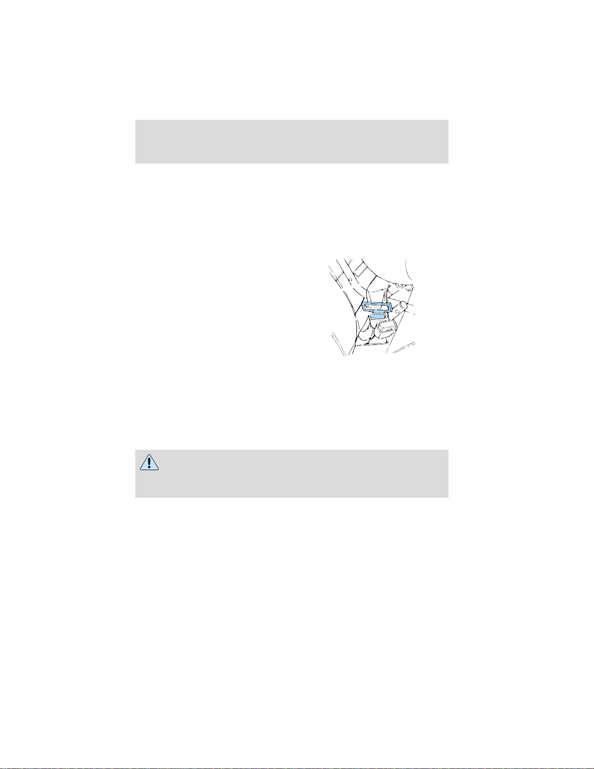
Seating and safety restraints
Child and infant or child safety seats
Use a safety seat that is recommended for the size and weight of the
child. Carefully follow all of the manufacturer’s instructions with the
safety seat you put in your vehicle. If you do not install and use the
safety seat properly, the child may be injured in a sudden stop or
collision.
When installing a child safety seat:
• Use the correct safety belt buckle
for that seating position.
• Insert the belt tongue into the
proper buckle until you hear a
snap and feel it latch. Make sure
the tongue is securely fastened in
the buckle.
• Keep the buckle release button
pointing up and away from the
safety seat, with the tongue
between the child seat and the release button, to prevent accidental
unbuckling.
• Place seat back in upright position.
Ford recommends the use of a child safety seat having a top tether
strap. Install the child safety seat in a seating position which is capable
of providing a tether anchorage. For more information on top tether
straps, refer to Attaching safety seats with tether straps.
Carefully follow all of the manufacturer’s instructions included
with the safety seat you put in your vehicle. If you do not install
and use the safety seat properly, the child may be injured in a sudden
stop or collision.
73
Page 74
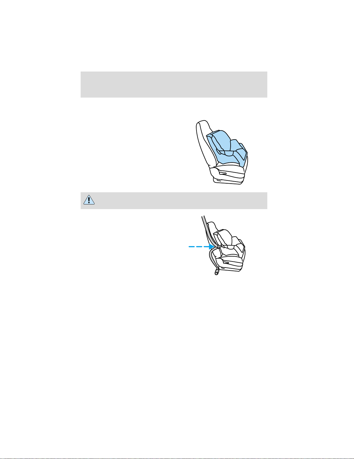
Seating and safety restraints
Installing child safety seats in combination lap and shoulder belt
seating positions
1. Position the child safety seat in a
seat with a combination lap and
shoulder belt.
Children should always be restrained in the rear seat when
possible.
2. While holding the shoulder and
lap belt portions together, route the
tongue through the child seat
according to the child seat
manufacturer’s instructions. Be sure
the belt webbing is not twisted.
74
Page 75
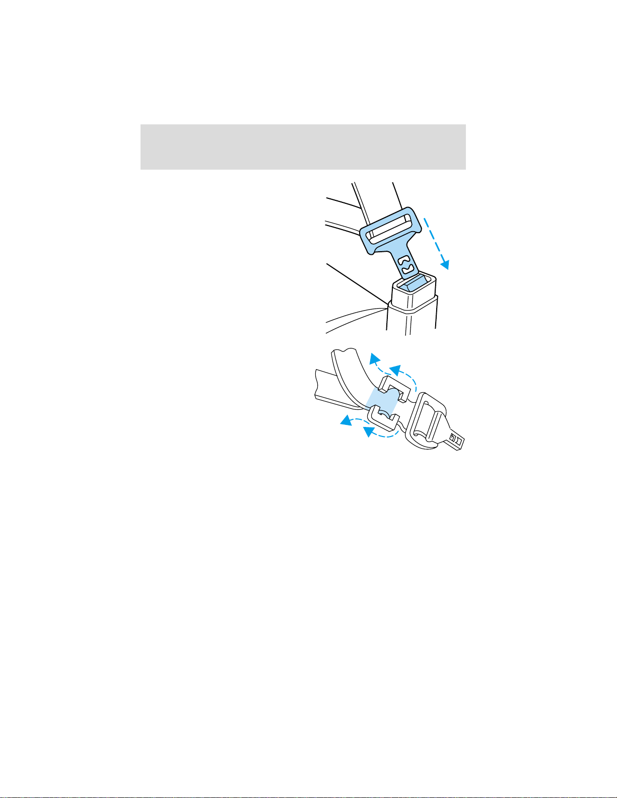
Seating and safety restraints
3. Buckle the seat belt. Push down
on the childseat and pull on the
shoulder portion of the belt to snug
the lap belt. Hold the lap and
shoulder belts next to the tongue
and unbuckle the belt.
4. Install a locking clip over both lap
and shoulder belt portions next to
the sliding tongue. Rebuckle the
belt. Obtain the locking clip kit
(Part Number FO3Z-5461248–A) at
no charge from an authorized Ford
or Lincoln-Mercury dealer.
5. Before placing the child in the seat, forcibly tilt the seat forward and
back to make sure the seat is securely held in place. If the child seat is
not tight enough, unbuckle the seat belt, move the tongue and locking
clip to shorten the lap portion and push down hard on the childseat
while you rebuckle the belt.
Check to make sure the child seat is properly secured before each use.
Attaching safety seats with tether straps
Some manufacturers make safety seats that include a tether strap that
goes over the back of the vehicle seat and attaches to an anchoring
point. Other manufacturers offer the tether strap as an accessory.
Contact the manufacturer of your child safety seat for information about
ordering a tether strap.
75
Page 76

Seating and safety restraints
Tether anchorage hardware
A tethered seat can be installed in the front seat. Put the tether strap
over the seatback and attach it to an anchor bracket.
An anchor bracket can be installed to the inside of the back panel of
your vehicle.
The anchor bracket must be installed using the instructions provided
with the tether anchorage hardware kit.
Tether anchorage hardware kits (part number 613D74) including
instructions, may be obtained at no charge from any Ford or
Lincoln/Mercury dealer.
If you have a Super Cab or Crew Cab, Ford recommends you attach
tether safety seats in the rear seating position (if possible) with the
tether strap attached to the tether anchorage bracket as shown in the
instructions provided with the tether anchor kit.
Tighten the anchor according to specifications. Otherwise, the
safety seat may not be properly secured and the child may be
injured in a sudden stop or collision.
76
Page 77
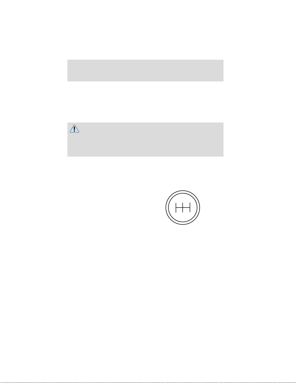
Starting
STARTING PROCEDURES
Operating precautions
• Always shift to a lower gear at high altitudes to prevent engine
smoking.
• Avoid extended and unnecessary idling.
Do not operate a diesel engine where the vapors can be
combustible. These vapors can be sucked through the air intake
system and cause engine acceleration and overspeeding, which may
result in bodily injury and extensive property damage. The equipment
owner and operator are responsible for safe operation in a hostile
environment.
STARTING THE ENGINE
1. Ensure headlamps and all accessories are turned off and the parking
brake is applied.
2. Automatic transmissions, ensure gearshift is in N (Neutral).
3. Manual transmissions, ensure
gearshift is in neutral position and
clutch pedal depressed.
R 2 4
1
3 5
If your vehicle is equipped with an
air intake heater, the heater will
activate in cooler weather. If the
Wait to Start light illuminates, do
not crank the engine until the light
goes off.
WAIT
TO
START
77
Page 78
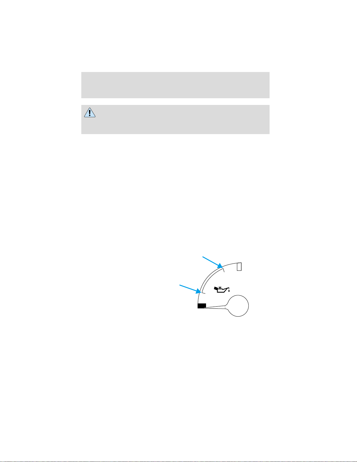
Starting
If equipped with an air intake heater, DO NOT use ether or any
other starting fluids. The use of starting fluids (ether) in an
engine equipped with an air intake heater could result in damage
and/or personal injury.
4. Do not depress the accelerator during starting the engine.
5. Start the engine.
If the engine does not start after 30 seconds of cranking, allow two
minutes for the starter to cool before trying again. Excessive cranking
may damage the starter.
After the engine starts:
• On some engines, the Wait to
Start light should illuminate after
the engine starts. Allow the
engine to idle about three
minutes or until the engine
coolant temperature gauge begins
to rise. Maintain idle speed until
the Wait to Start light cycles off
to indicate the air intake heater
has shut off (approximately six minutes). Operating the engine at
higher speeds will reduce the effectiveness of the air inlet heater.
• Do not increase engine speed
until the oil pressure gauge
indicates normal pressure.
• Ensure engine oil pressure is
indicated on the gauge within 15
seconds after starting.
• Idle the engine for three to five
minutes before operating with a
full load.
• Try to limit engine idle to 10
minutes. Excessive idling reduces fuel economy.
• When starting a cold engine, increase the engine speed (RPM) slowly
to make sure adequate lubrication is available to the bearings.
WAIT
TO
START
H
L
78
Page 79
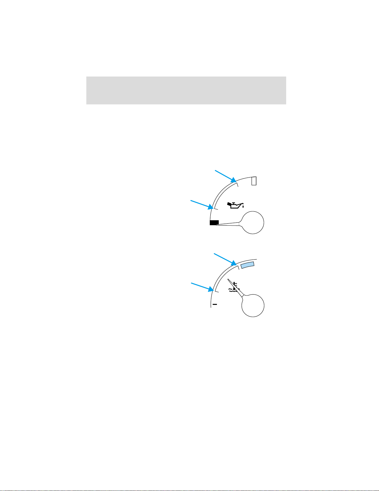
Starting
RESTARTING AFTER RUNNING OUT OF FUEL
The fuel system may need to be purged of air, refer to Running out of
fuel in the Maintenance and care chapter.
OPERATING THE ENGINE
Do not operate the engine at full throttle below peak torque engine
speed (RPM) for more than one minute at a time (peak torque RPM
varies from 1200-1500 RPM depending on engine rated speed).
Monitor the oil pressure and coolant
temperature gauges frequently.
If the gauges indicate any reading is
not in the normal operating range,
stop your vehicle as soon as
possible, shut the engine off and
check the appropriate fluid level. If
an overheating condition starts to
occur, release the throttle pressure
or shift the transmission into a
lower gear, or both, until the
temperature returns to normal operating range.
Continuous operation with low coolant
temperature, below 60°C (140°F) or
high coolant temperature 100°C
(212°F) can damage the engine.
Most failures give some kind of early
warning. Look and listen for changes
in performance, sound or engine
appearance that can indicate service
or engine repair is needed. Some
changes to look and/or listen for:
L
C
H
H
• Engine misfires
• Loss of power
• Sudden changes in engine operating temperature or oil pressure
• Excessive smoke
• Fuel, oil or coolant leaks
• Vibration
• Increased oil or fuel consumption
79
Page 80

Starting
Excessive full throttle operation below peak torque RPM will shorten
engine life to overhaul and can cause serious engine damage. Operation
of the engine below peak torque RPM can occur during gear shifting due
to difference of gear ratios.
COLD WEATHER STARTING
Perform the following to assure efficient starting in cold weather:
• Use the proper grade oil for your climate. Refer to your engine
operator’s manual for proper grade oil.
• Test the battery more frequently to assure ample power for starting.
• All electrical connections should be tight and in good condition to
prevent losses through loose or corroded connections.
USING THE ENGINE BLOCK HEATER (IF EQUIPPED)
An engine block heater warms the engine coolant, which improves
starting, warms up the engine faster and allows the heater-defroster
system to respond quickly. Use of an engine block heater is strongly
recommended if you live in a region where temperatures reach -23°C
(-10°F) or below.
For best results, plug the heater in at least three hours before starting the
vehicle. Using the heater for longer than three hours will not harm the
engine, so the heater can be plugged in the night before starting the vehicle.
To prevent electrical shock, do not use your heater with
ungrounded electrical systems or two-pronged (cheater)
adapters.
ENGINE SHUTDOWN SYSTEM (IF EQUIPPED)
This system is designed to help prevent engine damage that could result
from operating the engine during a prolonged period of low engine oil
pressure, high engine coolant temperature or low coolant level. If any of
these conditions occur, a warning light will illuminate and a chime will
sound warning the operator that the engine will shutdown in 30 seconds.
This is to allow time for the operator to move the vehicle off the road. If
additional time is required, the engine can be restarted and run each
time for approximately 30 seconds.
Do not attempt to use this restarting feature to drive the vehicle, serious
engine damage could result.
80
Page 81

Driving
EXHAUST FUMES
Never idle the engine in closed areas. Never sit in a parked or
stopped vehicle for any amount of time with engine running.
If you ever smell exhaust fumes of any kind inside your vehicle,
have your dealer inspect and fix your vehicle immediately. Do
not drive if you smell exhaust fumes. These fumes are harmful and
could kill you.
In order to guard against fumes entering your vehicle, the exhaust
system and body ventilation system should be checked by a qualified
technician:
• Each time the vehicle is raised for service.
• Whenever a change in exhaust system noise is noted.
• Whenever the vehicle has been damaged by impact from another
vehicle, object or road obstruction.
In order to afford proper operation, all air inlet vents should be kept
clear of snow, leaves and other debris.
If you run the engine while stopped (idled) in an unconfined area, open
the windows at least 2.5 cm (one inch) and adjust the heating or air
conditioning to draw outside air into the vehicle as follows:
• If your vehicle has outside air control vents, open them fully.
• Set fan speed on high with function control to any position except
OFF or MAX A/C and the temperature control on any desired position.
• Adjust air control system to force outside air into the vehicle.
BACKING UP
To avoid the possibility of personal injury while backing the
vehicle, always be sure your vehicle’s path is clear.
Before backing your vehicle, be sure you can do so safely. If anything
behind the cab limits your view, do not rely on mirrors alone to assure
that your intended path is clear. If other persons are in the vicinity, have
someone standing well behind the vehicle and outside your intended
path - visible through an exterior mirror - guide you as you back up.
81
Page 82

Driving
Although OSHA or other governmental regulations may require use of an
electrical or mechanical back-up alarm to warn bystanders, such an
alarm does not assure that the intended path is clear.
An electrical back-up alarm, if installed, is connected to the back-up
lamp circuit.
HYDRAULIC BRAKES (IF EQUIPPED)
Your service brakes are self-adjusting. Refer to the Scheduled
maintenance guide for scheduled maintenance.
Occasional brake noise is normal and often does not indicate a
performance concern with the vehicle’s brake system. In normal
operation, automotive brake systems may emit occasional or intermittent
squeal or groan noises when the brakes are applied. Such noises are
usually heard during the first few brake applications in the morning;
however, they may be heard at any time while braking and can be
aggravated by environmental conditions such as cold, heat, moisture,
road dust, salt or mud. If a “metal-to-metal,”“continuous grinding” or
“continuous squeal” sound is present while braking, the brake linings
may be worn-out and should be inspected by a qualified service
technician.
If you are driving down a long or steep hill, shift to a lower gear.
Do not apply your brakes continuously, as they may overheat
and become less effective.
Four-wheel anti-lock brake system (ABS)
On vehicles equipped with an anti-lock braking system (ABS), a noise
from the hydraulic pump motor and pulsation in the pedal may be
observed during ABS braking events. Pedal pulsation coupled with noise
while braking under panic conditions or on loose gravel, bumps, wet or
snowy roads is normal and indicates proper functioning of the vehicle’s
anti-lock brake system. If the vehicle has continuous vibration or shudder
in the steering wheel while braking, the vehicle should be inspected by a
qualified service technician.
82
Page 83

Driving
The ABS operates by detecting the
onset of wheel lockup during brake
applications and compensating for
this tendency. The wheels are
prevented from locking even when
the brakes are firmly applied. The
accompanying illustration depicts
the advantage of an ABS equipped
vehicle (on bottom) to a non-ABS
equipped vehicle (on top) during hard braking with loss of front braking
traction.
Servicing or replacing ABS module
1. Remove any contamination from the exterior of the module assembly
before disconnecting any brake tubes. Keep the contamination away from
all open ports and brake tubes.
2. Mark and tag all brake tubes and electrical connectors before
disassembly.
3. Perform the necessary repair.
4. Using the marked tags from disassembly, connect the brake tubes and
electrical connectors.
Always mark and tag the brake tubes and the electrical
connectors prior to disassembly to ensure correct assembly and
prevent brake failure.
ABS warning lamp
ABS
The
warning lamp in the instrument cluster momentarily illuminates
when the ignition is turned on and the engine is off. If the light does not
illuminate momentarily at start up, remains on after the vehicle reaches
10 to 15 km/h (5 to 10 mph), or continues to flash, the ABS needs to be
serviced.
With the ABS light on, the anti-lock brake system is disabled and normal
braking is still effective unless the brake warning light also remains
illuminated. (If your parking brake warning lamp illuminates, have your
vehicle serviced immediately).
83
Page 84

Driving
Using ABS
• In an emergency or when maximum efficiency from the ABS is
required, apply continuous full force on the brake. The ABS will be
activated immediately, thus allowing you to retain full steering control
of your vehicle and, providing there is sufficient space, will enable you
to avoid obstacles and bring the vehicle to a controlled stop.
• The Anti-Lock system does not decrease the time necessary to apply
the brakes or always reduce stopping distance. Always leave enough
room between your vehicle and the vehicle in front of you to stop.
• We recommend that you familiarize yourself with this braking
technique. However, avoid taking any unnecessary risks.
Hydraulic brake booster system (Hydromax)
The Hydromax systems receive fluid pressure from the power steering
pump to provide power assist during braking.
The Hydromax booster receives backup pressure from the reserve
system electric pump whenever the fluid in the power steering system is
not flowing. When the engine is OFF, the pump will turn on if the brake
pedal is applied, or if the ignition is turned to the ON position.
The sound of the pump operating may be heard by the driver, but this is
a normal characteristic of the system.
The reserve system provides reduced braking power, so the vehicle
should be operated under these conditions with caution, and only to seek
service repair and remove the vehicle from the roadway.
For Hydromax under normal operating conditions noise of the fluid
flowing through the booster may be heard whenever the brake is applied.
This condition is normal. Vehicle service is not required.
If braking performance or pedal response becomes very poor, even when
the pedal is strongly applied, this may indicate the presence of air in the
hydraulic system or fluid leakage. Stop the vehicle safely as soon as
possible and seek service immediately.
If the red BRAKE warning lamp in
the instrument cluster remains
illuminated after engine start up,
this indicates a system failure in the
master cylinder of the brake system.
Stop the vehicle safely as soon as possible and seek service immediately.
BRAKE
!
84
Page 85
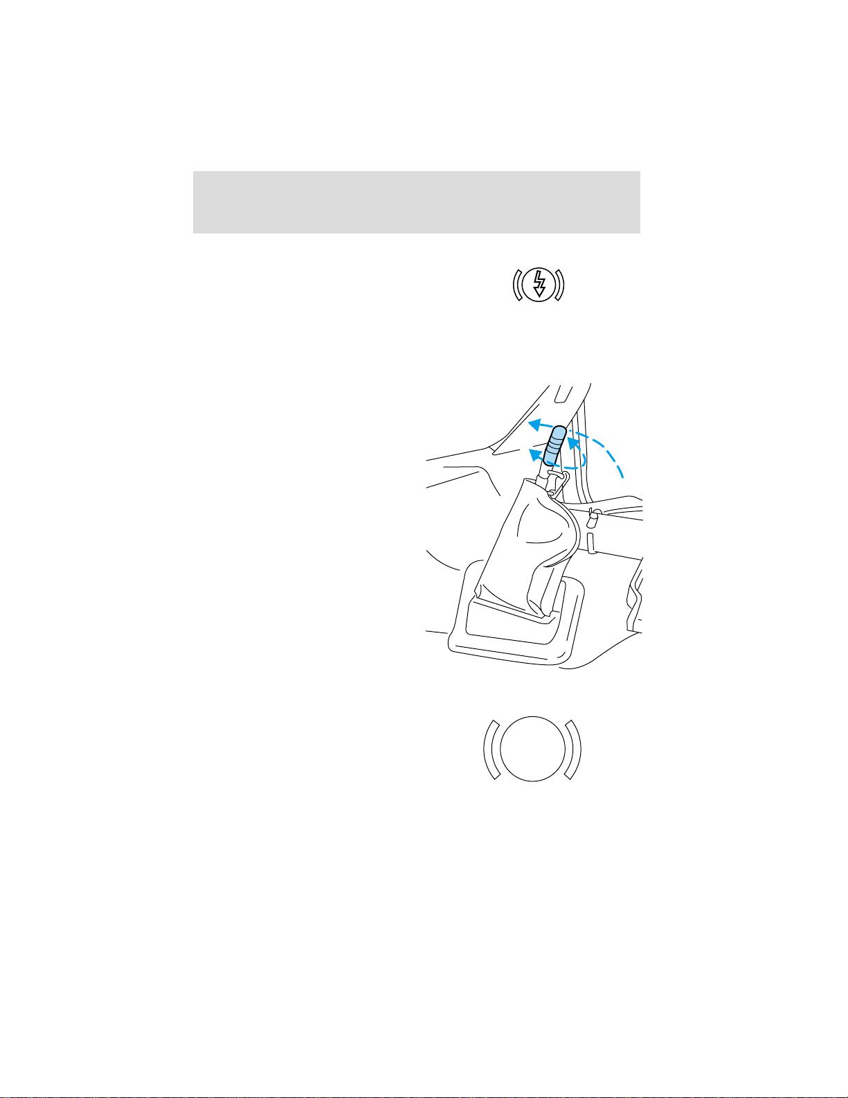
Driving
If the yellow BRAKE RESERVE
(E-motor) warning light remains on
while the engine is running, this
indicates inadequate hydraulic
booster pressure or reserve pump
system failure. Stop the vehicle safely as soon as possible and seek
service immediately.
Parking brake
Apply the parking brake whenever
the vehicle is parked. To set the
parking brake, pull handle up until it
snaps into the locked position.
A properly adjusted parking brake
requires approximately 116 Nm (90
lb-ft) to activate. For maximum
parking brake effectiveness turn
handle clockwise to adjust for wear.
When the parking brake is out of
adjustment, seek service
immediately.
BRAKE
The parking BRAKE warning lamp
in the instrument cluster illuminates
and remains illuminated (when the
ignition is turned ON) until the
parking brake is released.
BRAKE
P
85
Page 86
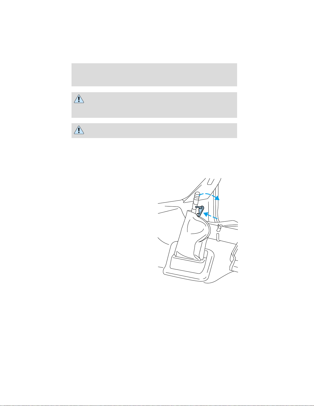
Driving
Do not use the gearshift selector in place of the parking brake.
Always set the parking brake fully AND make sure the gearshift
selector is in R (Reverse) for vehicles equipped with manual
transmission or N (Neutral) for vehicles with automatic transmission.
Unexpected and possible sudden vehicle movement may occur if
these precautions are not taken.
The parking brake is not recommended to stop a moving vehicle.
However, if the normal brakes fail, the parking brake can be used to stop
your vehicle in an emergency. Since the parking brake only applies
retardation to the rear wheels, the vehicle’s stopping distance will
increase greatly and the handling of your vehicle will be adversely
affected.
Push the palm release lever on the
parking brake handle and push
down as far as possible to release
the brake. Driving with the parking
brake on will cause the brakes to
wear out quickly and reduce fuel
economy.
86
Page 87
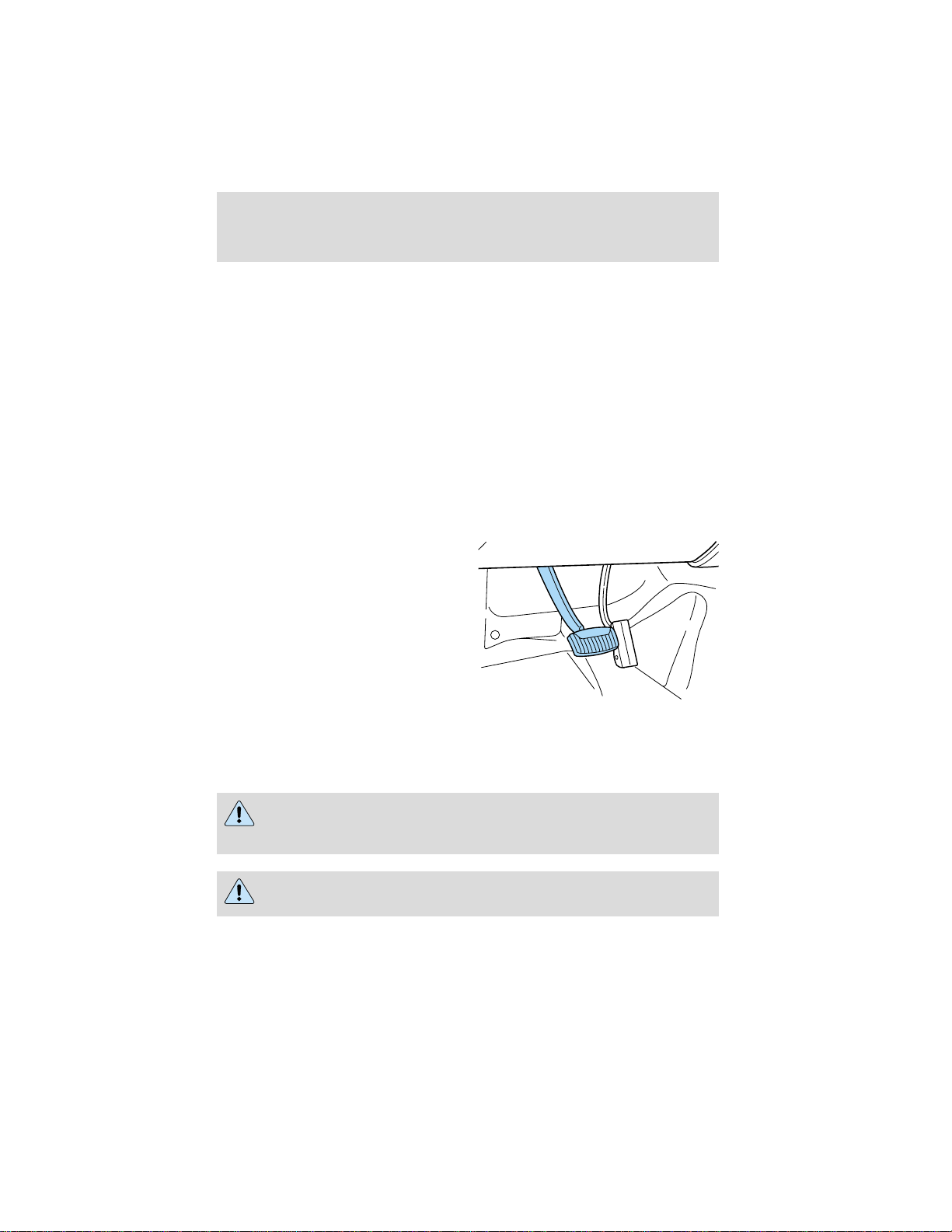
Driving
Burnish procedure
For optimal performance of a new parking brake system/new linings
perform the following procedure:
1. Make ten stops from 40 km/h (20 mph) with the parking brake lever
force set at 18kg (40 lbs).
2. While driving the vehicle at 40 km/h (20 mph) apply the parking brake
(with applicable force to set to approximately 18kg [40 lbs.]). Allow the
vehicle to come to a complete stop, release the parking brake.
3. Drive 16.8 km (1.5 miles) to cool the brakes.
4. Repeat steps 1 through 3 ten times.
AIR BRAKES (if equipped)
Foot service brakes
Air brakes are operated by a
standard dash-mounted foot pedal.
All standard equipment brakes are
designed to be self-adjusting.
Automatic adjustment, when
required, occurs whenever the
brakes are applied and released
during forward or reverse operation.
Know the required stopping
distances for all driving conditions
that may be encountered. For longer brake lining life, take full advantage
of engine braking power when coming to a stop.
Before descending a long or steep hill, shift to a lower gear and avoid
continuous application of the brakes.
Do not drive with your foot resting on the brake pedal. This will
result in abnormally high brake temperatures, excessive lining
wear and increased stopping distances.
Continuous application of the brakes will cause the brakes to
overheat, resulting in a temporary loss of braking.
Occasional or intermittent brake squeal may result from environmental
conditions such as cold, hot, wet, snow, salt, mud, etc. This condition will
87
Page 88
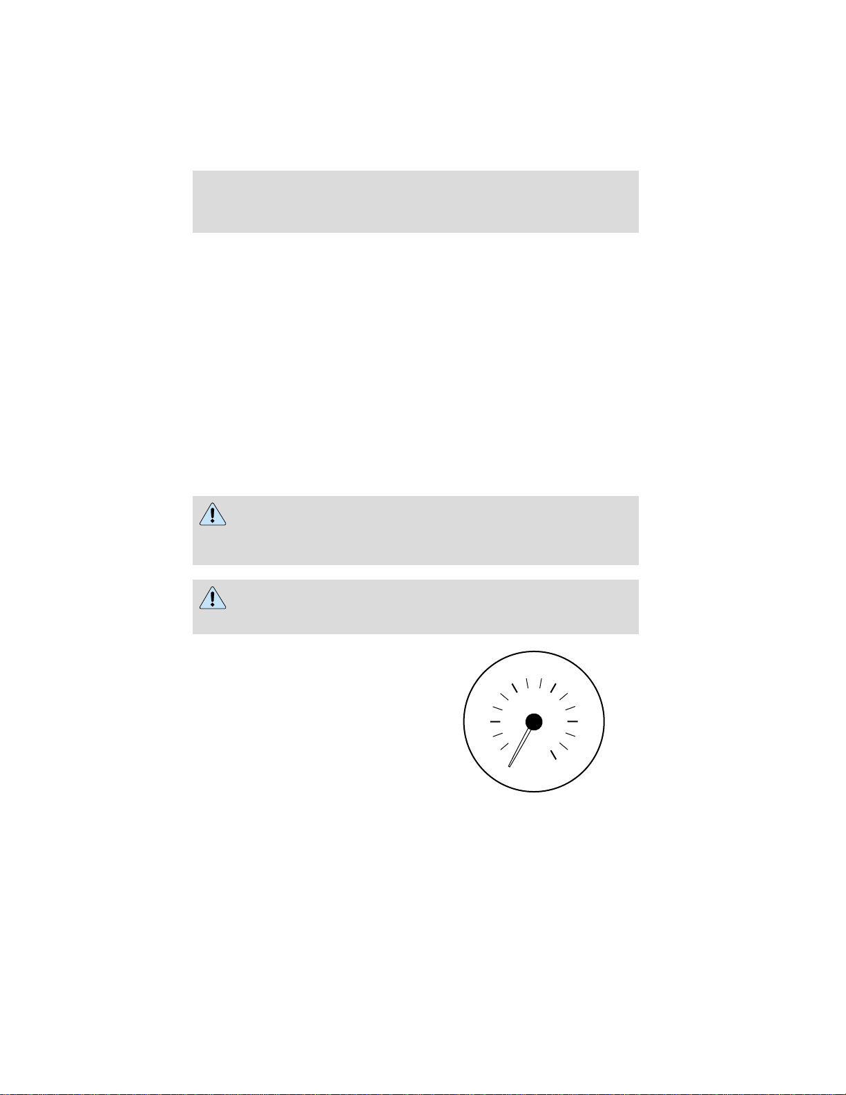
Driving
not affect braking effectiveness. The brakes should be checked only if
squeal occurs continuously with every application.
If brakes do not grip well
• If you have been driving through deep water, gently apply the brakes
several times while the vehicle is moving slowly.
• Let the brakes cool if you have been using them excessively, as in
mountain driving or after several fast, high speed stops.
• Check brake adjustment.
• Check brake linings for excessive wear.
• Check system air pressure.
Air brakes
After starting the engine, give the air compressor time to build up the air
pressure to 414 kPa (60 psi) before moving the vehicle.
Do not drive or continue to drive if the low air pressure buzzer
is sounding or the brake warning light is lit. These warnings
indicate that air pressure is not to normal operating level. Continued
use of the vehicle could result in loss of braking ability.
Avoid repeated light application of the brake pedal. This will
deplete air pressure faster and could result in loss of braking
capability.
Periodically check the air pressure
gauge while driving. Pressure should
range between approximately 703 to
930 kPa (105-135 psi). The air
compressor governor cut-in and
cut-out pressure settings are preset
at the factory and are not
adjustable.
88
9060
PSI
30 120
0
PRESSURE
AIR
150
Page 89
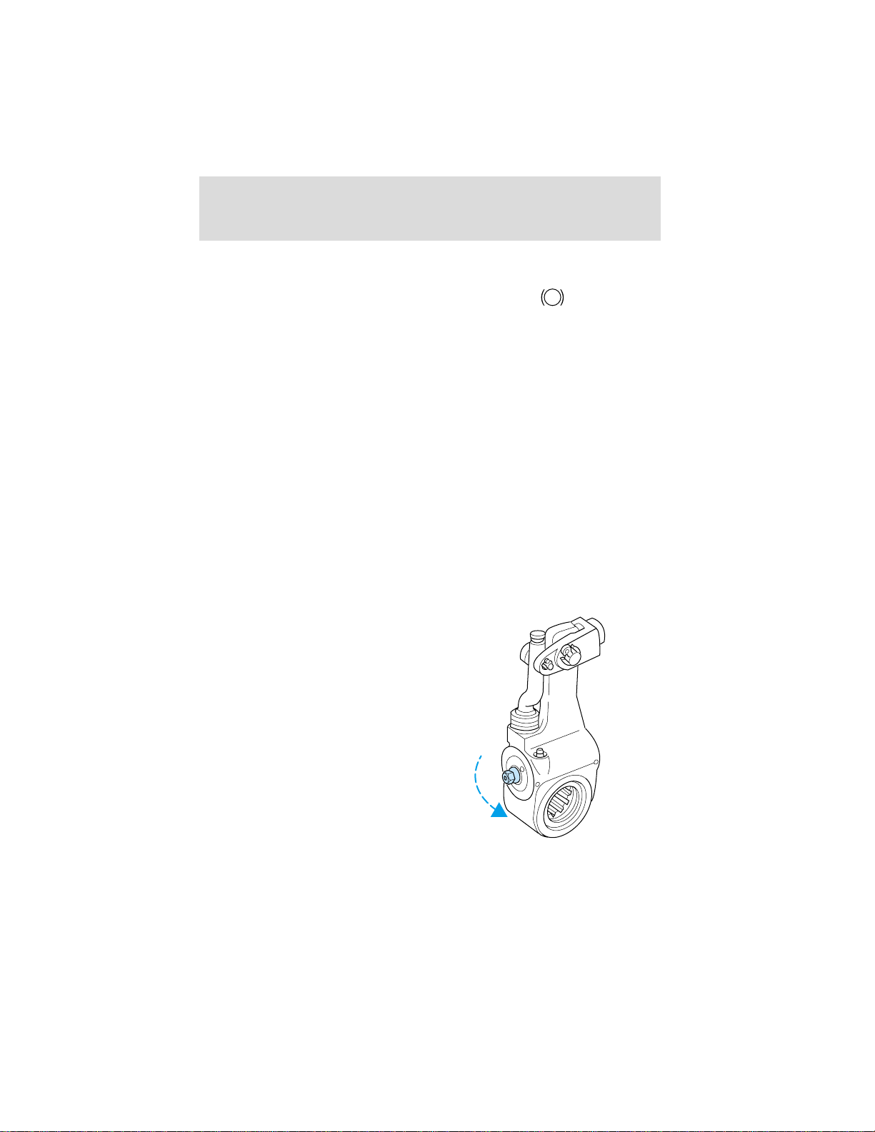
Driving
When air pressure is insufficient
(below 534 kPa [60 psi]), a warning
light illuminates and a buzzer
sounds when the ignition is in the
ON position.
This condition may be caused by excessive brake applications depleting
the system air pressure. If this condition occurs, stop driving the vehicle
until the compressor has fully recharged the air system. Do not move the
vehicle in this condition because the brake system may be inoperative.
Select a gear ratio to help slow your vehicle before descending grades.
Supplement with brakes as required to safely slow the vehicle and avoid
overspeeding the engine.
Air chamber stroke indication
All Ford air chamber push rods have orange stroke indicator stripes that
alert the operator when the braking system requires adjustment or
repair. The orange stripe is painted on the air chamber push rod at the
slack adjuster readjustment stroke dimension.
Air brake inspection and adjustment should be performed by a qualified
service technician in accordance with the instructions in the Ford Truck
Service Manual.
Cam brakes—automatic slack adjusters
Standard air brakes (cam) are
equipped with automatic brake
adjusters. Automatic adjustment
occurs during forward and reverse
brake applications. Inspect brakes
for proper adjustment at the
intervals listed in the vehicle Service
Maintenance Guide.
BRAKE
!
89
Page 90

Driving
Emergency air brake
All vehicles are equipped with a dual brake system. In the unlikely event
of a failure of one system, the second system will function for emergency
stopping. These systems are all controlled by the brake pedal in the
same manner as for normal stops.
Do not continue to operate the vehicle with a failure of one of
the systems. Take the vehicle to your dealer for service
immediately.
Anti-lock braking system (if equipped)
For information on the anti-lock braking system (ABS), refer to
Hydraulic brakes in this chapter.
Driving with ABS
The ABS system functions just like a standard air brake system. Maintain
a steady brake pedal application; you do not need to pump or remove
your foot from the pedal. The ABS keeps the wheels rolling during
braking to maintain control and reduce stopping distances.
Parking brake
Do not use the gearshift selector in place of the parking brake.
Always set the parking brake fully AND make sure the gearshift
selector is in R (Reverse) for vehicles equipped with manual
transmission or N (Neutral) for vehicles with automatic transmission.
Unexpected and possible sudden vehicle movement may occur if
these precautions are not taken.
If the service brakes should fail to operate while the vehicle is in motion,
you can make an emergency stop with the parking brake. The stopping
distance, however, will be much greater than normal. Repairs should be
made immediately to an inoperative air brake system circuit.
90
Page 91

Driving
Parking brake control
Pull the yellow parking brake knob
out to apply the parking brake. Push
the knob in to release the parking
brake.
This control is used for
parking only. Do not leave
the vehicle unattended after
setting the parking brake without
placing the transmission in R
(Reverse) for manual transmission
or N (Neutral) for automatic
transmission. Use of wheel chocks
is also recommended in hilly or
off-road usage.
Releasing spring brake with air pressure
The air system in all vehicles with spring-actuated rear wheel parking
brakes is equipped with a tank valve located on the supply or service air
tank for connection to an outside air supply. The valve permits the
system to be recharged with air from an outside source, releasing the
spring-actuated parking brakes. The vehicle may then be towed in an
emergency.
An outside air source can be used only if the protected system is in
operating condition. If air pressure cannot be restored in the protected
air system, the spring-actuated brakes must be released manually.
Releasing spring brake manually
PARKING
BRAKE
PUSH TO
APPLY
PULL TO
RELEASE
Do not attempt to disassemble the parking brake chamber under
any circumstances. The high spring load may cause serious
injury if the chamber clamps are removed.
If air pressure is released from the spring brake chamber the power
spring applies the brake and, unless air pressure can be re-established,
the spring brake must be released as follows in order to move the
vehicle.
91
Page 92
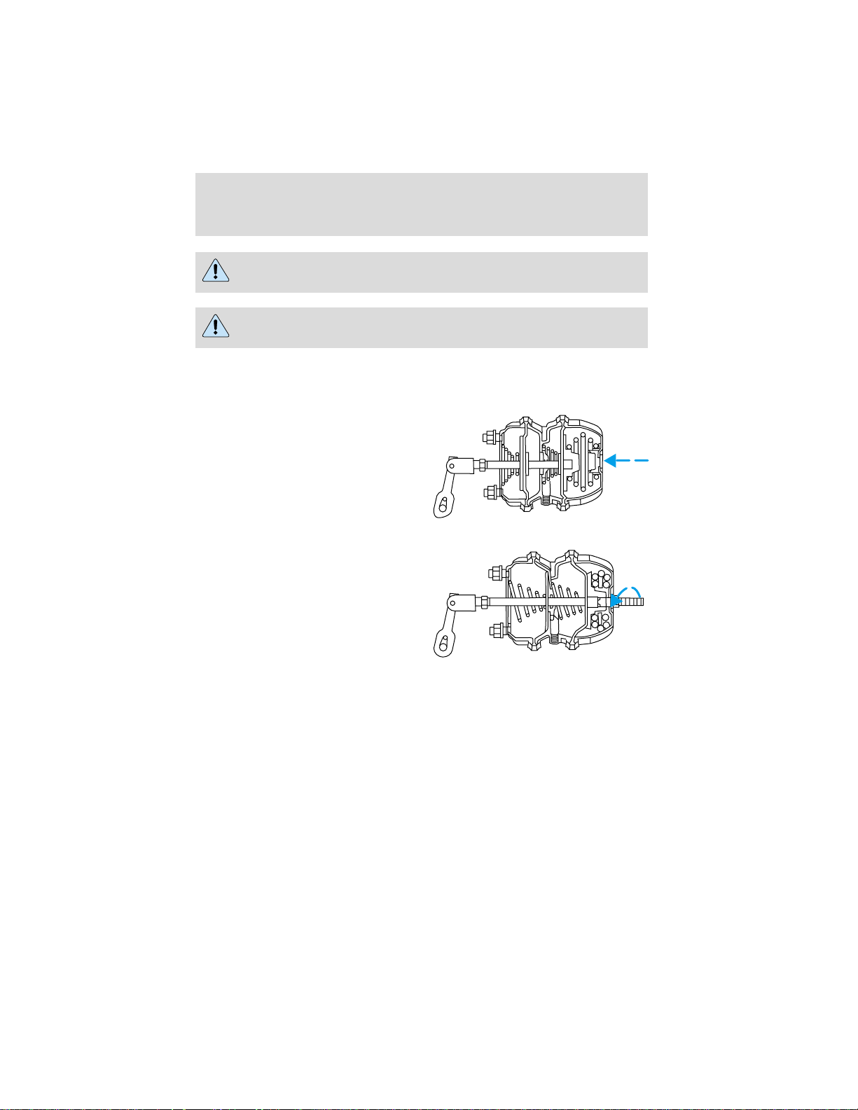
Driving
Block the wheels to prevent the vehicle from moving.
Unexpected and possibly sudden vehicle movement may occur if
these precautions are not taken.
Impact wrenches should not be used as they may damage the piston and
prevent proper caging of the spring. Do not apply more than 68 Nm (50
lb-ft) torque to the release bolt nut.
1. Remove the stud tool and nut
from the carrying pocket on the
brake chamber assembly.
2. Remove the access plug from the
end of the spring chamber.
3. Insert the release stud through
the opening in the chamber and into
the spring pressure plate.
4. Turn the release stud one-quarter
turn to engage the stud tangs with
the slot in the pressure plate. Keep
the stud engaged and install the nut
on the release stud.
5. Tighten the nut until the spring is
fully caged and the brakes are
released. Do not loosen or remove
the release stud and nut unless the brake chamber is completely
assembled and is securely clamped.
6. When the air pressure is restored, unscrew and remove the release
stud and install in the carrying pocket. Install the access plug.
92
Page 93
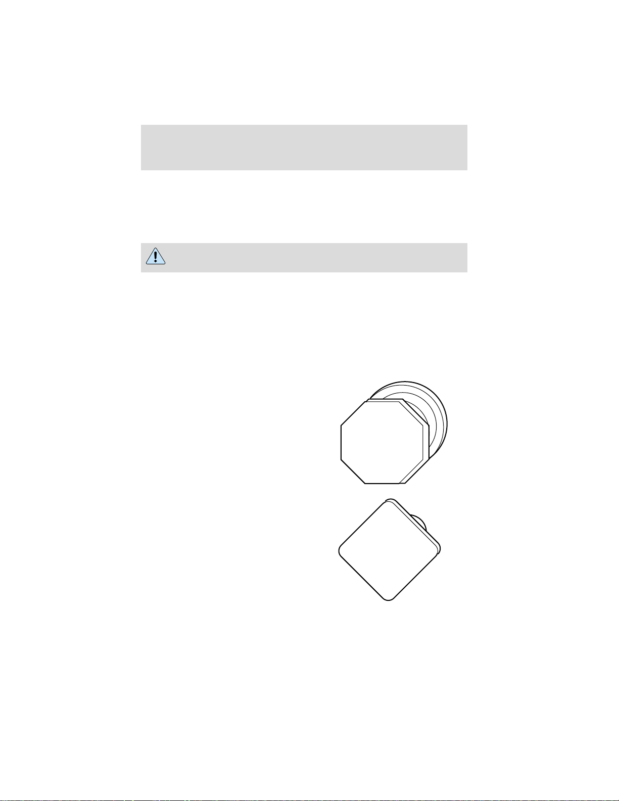
Driving
Trailer brake
During normal operation, the trailer brakes operate whenever the tractor
brakes are applied. A manual control lever is provided so the trailer
brakes can be applied separately, if required. To apply the trailer brakes,
pull the trailer brake control downward to the APPLIED position.
Do not use the trailer brake manual control lever for parking.
Trailer air supply control (MV-3) (Tractor package)
The MV-3 control module is a two-button, push-pull control valve housed
in a single body which includes a dual circuit supply valve and a check
valve.
Operation
During initial charge, with the system completely discharged, both
buttons are out.
When system pressure reaches
448 kPa (65 psi), the red control
(trailer supply) may be pushed in
and should stay in, charging the
trailer system and releasing the
trailer brakes.
PULL
TRAILER
AIR SUPPLY
NOT FOR PARKING
PUSH
TO
TO
EVACUATE
SUPPLY
The yellow control (parking brake)
may now be pushed in, which will
supply air to the tractor spring
brakes, releasing them.
TO
APPLY
PULL
PARKING
BRAKE
PUSH
RELEASE
TO
93
Page 94
Driving
Normal operating position
With both controls pushed in, air is supplied to the trailer and to the
tractor spring brakes; all brakes are released.
Actuation of trailer parking or emergency brakes
To actuate the trailer brakes only,
pull out the red control (trailer air
supply), exhausting the trailer
supply line. The trailer brakes are
now applied either by air emergency
or spring brakes, depending on the
type of trailer system. This mode
would be used to uncouple from the
trailer during bob-tail operation.
PULL
TRAILER
AIR SUPPLY
NOT FOR PARKING
PUSH
System park
With both controls in for normal run modes, the parking brakes on both
tractor and trailer may be actuated by pulling the yellow control (parking
brake) out, which exhausts the air from the tractor spring brakes and
simultaneously causes the red control (trailer supply) to pop out,
applying the trailer brakes. This complies with federal regulations stating
one control must apply all the parking brakes on the vehicle.
Trailer charge
If both controls are out when parking the combination vehicle and it is
desired to recharge the trailer (leaving the tractor spring brakes
applied), the trailer air supply control may be pushed in, repressurizing
the trailer supply line. This mode could also be used to park a
combination vehicle with air actuated emergency brakes on the trailer to
provide demonstrated parking capability with tractor spring brakes only.
Automatic application
With both controls in (in the normal run configuration), if the supply
pressure to the push-pull valves is reduced to approximately 240 to
310 kPa (35-45 psi), the red control (trailer supply valve) must pop out,
applying the emergency or parking brakes on the trailer. If the red
control is held in manually and the pressure decreases to approximately
172 to 240 kPa (25-35 psi), a tripper piston within the MV-3 valve will
move upward. This will exhaust the trailer supply, causing the required
TO
TO
EVACUATE
SUPPLY
94
Page 95
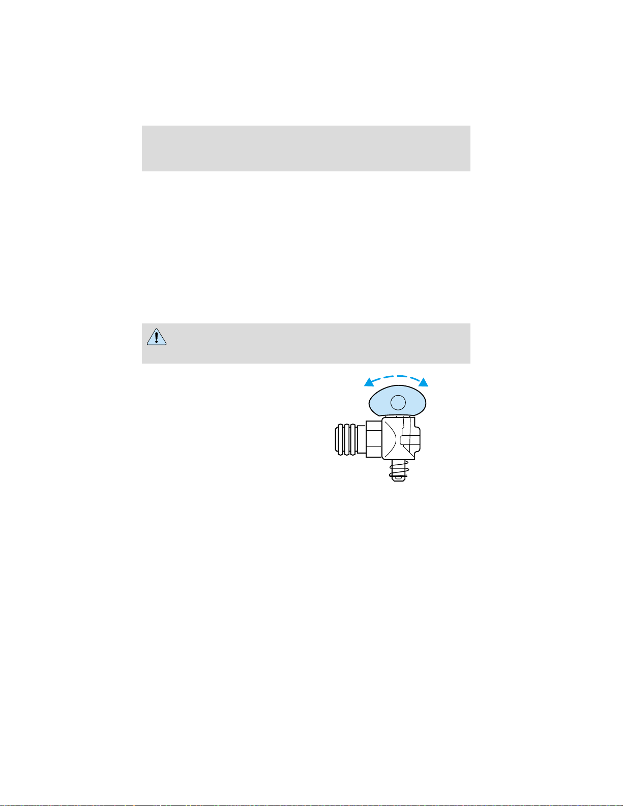
Driving
non-override feature. The yellow control (parking brake) will pop out at
approximately 138 to 207 kPa (20-30 psi).
Reservoir selection
The number one service reservoir will at all times be selected as the
primary supply source for the MV-3. This is accomplished automatically
by the function of the dual circuit supply valve contained in the body of
the MV-3. Only in the event of a pressure drop of more than 207 kPa
(30 psi) below that of the number two service reservoir will the dual
circuit supply valve shuttle and establish the front service reservoir as
the supply.
Air brake reservoir draining
Failure to drain air brake reservoirs can result in a reduction or
loss of braking ability due to fluid accumulation in the reservoir
and/or possible freeze-up during cold weather.
Drain all the air brake reservoirs
daily, completely to 0 kPa/psi, by
opening the draincock at the bottom
of the tanks. Close draincock after
complete draining. Air tanks
equipped with automatic moisture
ejector valves may also be drained
manually as required to maintain a
dry air system. Contact your dealer
if you are unsure of the air reservoir
locations or the draining procedure.
STEERING
Your vehicle is equipped with power steering. Power steering uses energy
from the engine to help steer the vehicle.
Never hold the steering wheel to the extreme right or the extreme left
for more than a few seconds when the engine is running. This action
could damage the power steering pump.
95
Page 96

Driving
Suspension and steering
The suspension and steering linkage in your vehicle should be inspected
periodically for the following:
• Spring leaf damage
• Spring sag
• Abnormal looseness
• Damaged seals.
The following changes indicate a need to inspect and service your vehicle:
• Changes in steering action.
• Hard steering.
• Excessive free play.
• Unusual sounds when turning or parking.
If the steering wanders or pulls
This condition can be caused by any of the following conditions:
• Underinflated tire(s) on any wheel(s)
• Front end out of alignment
• Total vehicle out of alignment (i.e. rear axle[s] out of alignment with
front axle)
• Improper adjustment in the steering gear
• Vehicle overloaded or unevenly loaded
• High crosswinds
• High crown in center of road
• Components in steering linkage loose or worn
• Wheel bearings improperly adjusted
• Excessive lash in steering shaft or universal joints
If the vehicle steers hard
Hard steering can be caused by any of the following conditions:
• Underinflated tire(s) on any wheel(s)
• Vehicle overload
• Misalignment of the front tires
96
Page 97
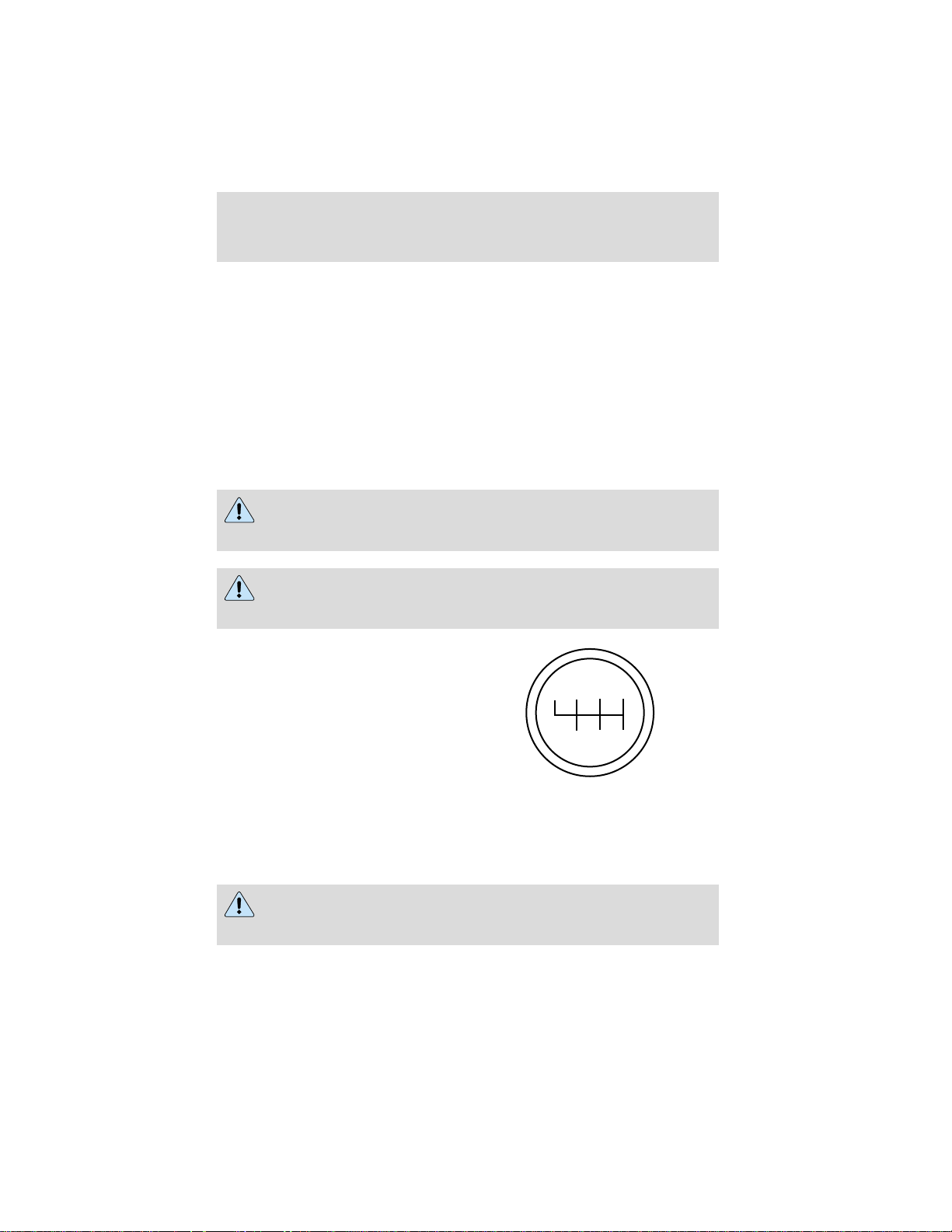
Driving
• Lack of lubricant in the front spindle bearings or linkage components
• Low oil level in the power steering system
• Broken or loose power steering pump direct drive connection
• Malfunctioning relief valve in power steering gear or steering pump
• Malfunctioning power steering pump
• Restriction in power steering lines
• Improperly set turn stops
• Air entrapped in power steering system fluid
DRIVING WITH A MANUAL TRANSMISSION, IF EQUIPPED
Continued use of a damaged or worn clutch, prolonged clutch
slippage or downshifting at excessive speeds can result in a
failure of the engine, transmission or clutch components.
To avoid premature clutch wear and failure, do not drive with
your foot resting on the clutch pedal or use it to hold the vehicle
at a standstill on an upgrade as when waiting for a traffic light.
Manual transmission shift patterns
are displayed on the shift lever
knob.
R 1 3 5
2
6
4
Study this information carefully before you drive the vehicle even though
you may be familiar with similar units. Do not attempt to drive the
vehicle without knowing the exact shift pattern of the transmission.
Consult your authorized dealer if any questions exist as to the shifting
instructions posted in your vehicle.
Do not coast the vehicle with the clutch pedal depressed or with
the transmission in neutral. This practice could result in loss of
vehicle control.
97
Page 98

Driving
Always use a gear ratio low enough to allow the engine to operate above
the minimum engine operation speed range. Do not lug the engine. When
more power is required, shift to a lower gear and accelerate the engine
near the governed speed.
Driving hints
The following driving hints are provided as a brief, general guide in
operating the different manual transmissions used in your vehicle.
• Always use the lowest gear to start the vehicle.
• Do not slam or jerk lever into gear.
• When shifting into 1 (First) or R (Reverse) with vehicle standing still,
quickly release and depress the clutch pedal (if necessary to complete
gear engagement).
Operating the Eaton FS-4205A and FS-5205A 5–speed
transmissions
The 5-speed transmission is
equipped with five forward gears
and one reverse. All forwards gears
are synchronized. The shift pattern
is embossed on the gear shift knob.
R 2 4
1
3 5
Do not shift the transmission into R (Reverse) while the vehicle is
moving as this could damage the transmission.
To go forward
With the engine idling, depress the
clutch pedal and shift into 1 (First).
Engage the clutch while pressing
R 2 4
the accelerator to start forward.
Operate the clutch and upshift as
required by driving conditions.
1
3 5
98
Page 99

Driving
To go backward
Reverse is obtained by putting the
gearshift lever in R (Reverse) and
engaging the clutch while pressing
lightly on the accelerator.
Operating the Eaton FS-5306A and FS–6306A 6-speed
transmissions
These 6-speed transmissions are
equipped with six forward gears and
one reverse. The 2nd, 3rd, 4th, 5th
and 6th gears are synchronized. The
shift pattern is embossed on the
gear shift knob.
Do not shift the transmission into 1 (First) or R (Reverse) while the
vehicle is moving as this could damage the transmission.
To go forward
With the engine idling, depress the
clutch pedal and shift into 1 (First).
Engage the clutch while pressing
the accelerator to start forward.
Operate the clutch and upshift as
required by driving conditions.
R 2 4
1
3 5
R 1 3 5
2
6
4
R 1 3 5
2
6
4
99
Page 100
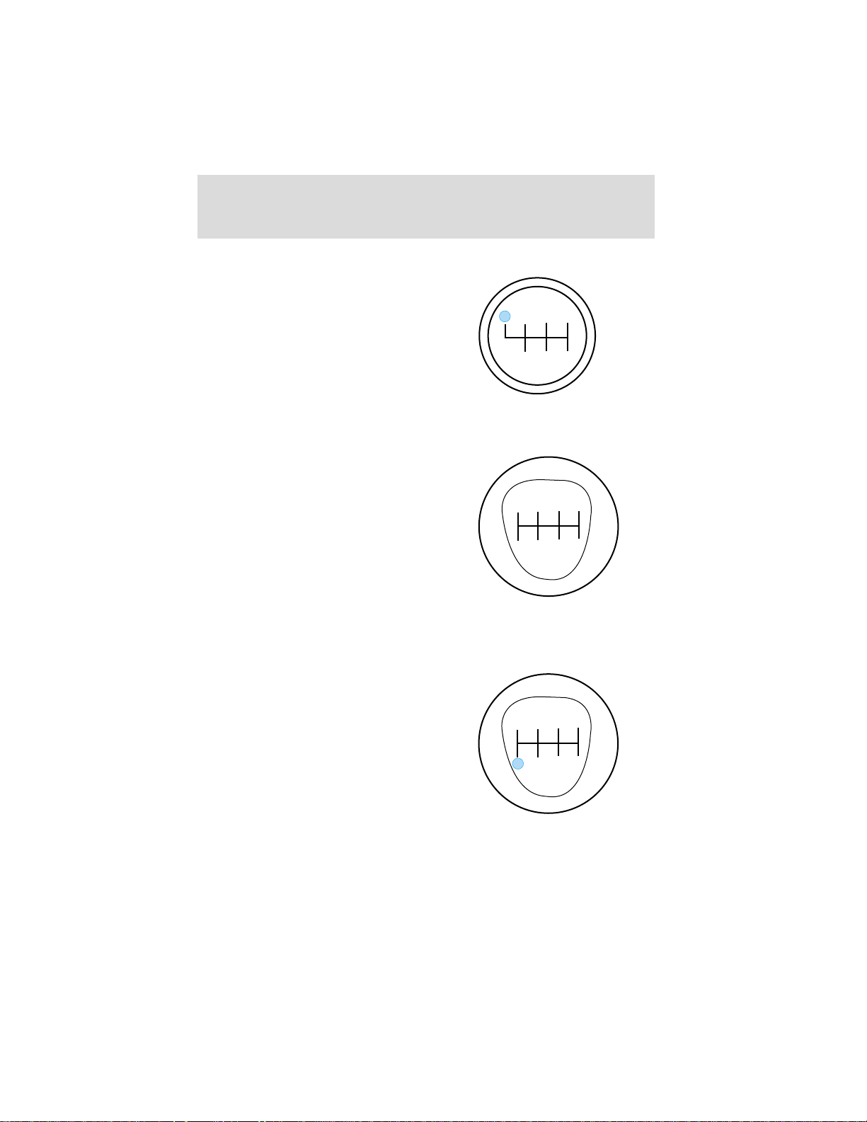
Driving
To go backward
Reverse is obtained by putting the
gearshift lever in R (Reverse) and
engaging the clutch while pressing
lightly on the accelerator.
Operating the Spicer ES52-7B and ES066-7B 7-speed
transmissions
These 7-speed transmissions are
equipped with seven forward gears
and one reverse. The 2nd, 3rd, 4th,
5th, 6th and 7th gears are
synchronized. The shift pattern is
embossed on the gear shift knob.
Do not shift the transmission into 1 (First) or R (Reverse) while the
vehicle is moving as this could damage the transmission.
To go forward
With the engine idling, depress the
clutch pedal and shift into 1 (First).
Engage the clutch while pressing
the accelerator to start forward.
Operate the clutch and upshift as
required by driving conditions.
R 1 3 5
2
6
4
R
2 4 6
1
3 5 7
R
2 4 6
1
3 5 7
100
 Loading...