

Page 1

Table of Contents
Introduction 4
Instrument Cluster 12
Warning and control lights 12
Gauges 16
Entertainment Systems 20
AM/FM stereo 20
AM/FM stereo cassette 22
AM/FM stereo with CD 25
AM/FM stereo cassette with CD 28
AM/FM stereo with in-dash six CD 32
Climate Controls 38
Heater only 38
Manual heating and air conditioning 39
Lights 41
Headlamps 41
Turn signal control 44
Bulb replacement 45
Driver Controls 52
Windshield wiper/washer control 52
Steering wheel adjustment 53
Moon roof 55
Power windows 57
Mirrors 59
Speed control 61
Message center 70
1
Page 2

Table of Contents
Locks and Security 75
Keys 75
Locks 75
Anti-theft system 77
Seating and Safety Restraints 85
Seating 85
Safety restraints 92
Air bags 105
Child restraints 114
Driving 125
Starting 125
Brakes 130
Transmission operation 133
Vehicle loading 161
Trailer towing 164
Recreational towing 188
Roadside Emergencies 192
Getting roadside assistance 192
Hazard flasher switch 193
Fuel pump shut-off switch 193
Fuses and relays 194
Changing tires 200
Jump starting 212
Wrecker towing 217
Customer Assistance 219
Reporting safety defects (U.S. only) 228
2
Page 3

Table of Contents
Cleaning 229
Maintenance and Specifications 236
Engine compartment 238
Engine oil 239
Battery 242
Fuel information 250
Air filter(s) 267
Tire Information 269
Part numbers 283
Refill capacities 284
Lubricant specifications 287
Accessories 302
Index 305
All rights reserved. Reproduction by any means, electronic or mechanical
including photocopying, recording or by any information storage and retrieval
system or translation in whole or part is not permitted without written
authorization from Ford Motor Company. Ford may change the contents without
notice and without incurring obligation.
Copyright © 2004 Ford Motor Company
3
Page 4

Introduction
CALIFORNIA Proposition 65 Warning
WARNING: Engine exhaust, some of its constituents, and
certain vehicle components contain or emit chemicals known to
the State of California to cause cancer and birth defects or other
reproductive harm. In addition, certain fluids contained in vehicles and
certain products of component wear contain or emit chemicals known
to the State of California to cause cancer and birth defects or other
reproductive harm.
CONGRATULATIONS
Congratulations on acquiring your new Ford. Please take the time to get
well acquainted with your vehicle by reading this handbook. The more
you know and understand about your vehicle, the greater the safety and
pleasure you will derive from driving it.
For more information on Ford Motor Company and its products visit the
following website:
• In the United States: www.ford.com
• In Canada: www.ford.ca
• In Australia: www.ford.com.au
• In Mexico: www.ford.com.mx
Additional owner information is given in separate publications.
This Owner’s Guide describes every option and model variant available
and therefore some of the items covered may not apply to your
particular vehicle. Furthermore, due to printing cycles it may describe
options before they are generally available.
Remember to pass on this Owner’s Guide when reselling the vehicle. It
is an integral part of the vehicle.
4
Page 5

Introduction
Fuel pump shut-off switch: In the event of an accident the
safety switch will automatically cut off the fuel supply to the
engine. The switch can also be activated through sudden vibration (e.g.
collision when parking). To reset the switch, refer to the Fuel pump
shut-off switch in the Roadside Emergencies chapter.
SAFETY AND ENVIRONMENT PROTECTION
Warning symbols in this guide
How can you reduce the risk of personal injury to yourself or others? In
this guide, answers to such questions are contained in comments
highlighted by the warning triangle symbol. These comments should be
read and observed.
Warning symbols on your vehicle
When you see this symbol, it is
imperative that you consult the
relevant section of this guide before
touching or attempting adjustment
of any kind.
Protecting the environment
We must all play our part in
protecting the environment. Correct
vehicle usage and the authorized
disposal of waste, cleaning and
lubrication materials are significant
steps towards this aim. Information in this respect is highlighted in this
guide with the tree symbol.
5
Page 6

Introduction
BREAKING-IN YOUR VEHICLE
Your vehicle does not need an extensive break-in. Try not to drive
continuously at the same speed for the first 1,000 miles (1,600 km) of
new vehicle operation. Vary your speed frequently in order to give the
moving parts a chance to break in.
Drive your new vehicle for at least 500 miles (800 km) before towing a
trailer or snowplowing.
Do not add friction modifier compounds or special break-in oils during the
first few thousand miles (kilometers) of operation, since these additives
may prevent piston ring seating. See Engine oil in the Maintenance and
Specifications chapter for more information on oil usage.
SPECIAL NOTICES
Emission warranty
The New Vehicle Limited Warranty includes Bumper-to-Bumper
Coverage, Safety Restraint Coverage, Corrosion Coverage, and 6.0L
Power Stroke Diesel Engine Coverage. In addition, your vehicle is eligible
for Emissions Defect and Emissions Performance Warranties. For a
detailed description of what is covered and what is not covered, refer to
the Warranty Guide that is provided to you along with your Owner’s
Guide.
Service Data Recording
Service data recorders in your vehicle are capable of collecting and
storing diagnostic information about your vehicle. This potentially
includes information about the performance or status of various systems
and modules in the vehicle, such as engine, throttle, steering or brake
systems. In order to properly diagnose and service your vehicle, Ford
Motor Company, Ford of Canada, and service and repair facilities may
access vehicle diagnostic information through a direct connection to your
vehicle when diagnosing or servicing your vehicle.
6
Page 7
Introduction
Event Data Recording
Other modules in your vehicle — event data recorders — are capable of
collecting and storing data during a crash or near crash event. The
recorded information may assist in the investigation of such an event.
The modules may record information about both the vehicle and the
occupants, potentially including information such as:
• how various systems in your vehicle were operating;
• whether or not the driver and passenger seatbelts were buckled;
• how far (if at all) the driver was depressing the accelerator and/or the
brake pedal;
• how fast the vehicle was traveling; and
• where the driver was positioning the steering wheel.
To access this information, special equipment must be directly connected
to the recording modules. Ford Motor Company and Ford of Canada do
not access event data recorder information without obtaining consent,
unless pursuant to court order or where required by law enforcement,
other government authorities or other third parties acting with lawful
authority. Other parties may seek to access the information
independently of Ford Motor Company and Ford of Canada.
Special instructions
For your added safety, your vehicle is fitted with sophisticated electronic
controls.
Please read the section Supplemental restraint system (SRS)
in the Seating and Safety Restraints chapter. Failure to follow
the specific warnings and instructions could result in personal injury.
Front seat mounted rear-facing child or infant seats should
NEVER be placed in front of an active passenger air bag.
7
Page 8

Introduction
Notice to owners of diesel-powered vehicles
Read the 6.0 Liter Power Stroke Direct Injection Turbo Diesel Owner’s
Guide Supplement for information regarding correct operation and
maintenance of your Diesel-powered light truck.
Notice to owners of pickup trucks and utility type vehicles
Utility vehicles have a significantly higher rollover rate than
other types of vehicles.
Before you drive your vehicle, please read this Owner’s Guide carefully.
Your vehicle is not a passenger car. As with other vehicles of this type,
failure to operate this vehicle correctly may result in loss of vehicle
control, vehicle rollover, personal injury or death.
Be sure to read Driving off road in the Driving chapter.
Using your vehicle with a snowplow
For more information and guidelines for using your vehicle with a
snowplow, refer to the Driving chapter.
Using your vehicle as an ambulance
If your light truck is equipped with the Ford Ambulance Preparation
Package, it may be utilized as an ambulance. Ford urges ambulance
manufacturers to follow the recommendations of the Ford Incomplete
Vehicle Manual, Ford Truck Body Builder’s Layout Book and the
Qualified Vehicle Modifiers (QVM) Guidelines as well as pertinent
supplements. For additional information, please contact the Truck Body
Builders Advisory Service at 1–877–840–4338.
Use of your Ford light truck as an ambulance, without the Ford
Ambulance Preparation Package voids the Ford New Vehicle Limited
Warranty and may void the Emissions Warranties. In addition, ambulance
usage without the preparation package could cause high underbody
temperatures, overpressurized fuel and a risk of spraying fuel which
could lead to fires.
8
Page 9
Introduction
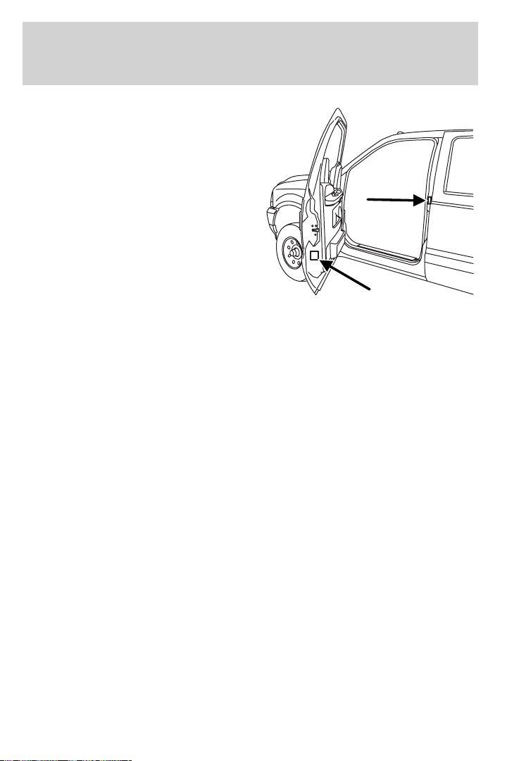
If your vehicle is equipped with the
Ford Ambulance Preparation
Package, it will be indicated on the
Certification label. The label is
located on the driver’s side door
pillar or on the rear edge of the
driver’s door. You can determine
whether the ambulance
manufacturer followed Ford’s
recommendations by directly
contacting that manufacturer. Ford
Ambulance Preparation Package is
only available on certain 6.0L Diesel
engine equipped vehicles.
Using your vehicle as a stationary power source (PTO)
Refer to the Driving chapter for more information and guidelines for
operating a vehicle equipped with an aftermarket power take-off system.
Middle East/North Africa vehicle specific information
For your particular global region, your vehicle may be equipped with
features and options that are different from the ones that are described
in this Owner’s Guide; therefore, a supplement has been supplied that
complements this book. By referring to the pages in the provided
supplement, you can properly identify those features, recommendations
and specifications that are unique to your vehicle. Refer to this
Owner’s Guide for all other required information and warnings.
9
Page 10

Introduction
These are some of the symbols you may see on your vehicle.
Vehicle Symbol Glossary
Safety Alert
Fasten Safety Belt Air Bag-Front
Air Bag-Side Child Seat
Child Seat Installation
Warning
Child Seat Tether
Anchor
Anti-Lock Brake System
Traction Control AdvanceTrac娂
Master Lighting Switch Hazard Warning Flasher
Fog Lamps-Front Fuse Compartment
See Owner’s Guide
Child Seat Lower
Anchor
Brake System
Brake Fluid Non-Petroleum Based
Fuel Pump Reset Windshield Wash/Wipe
Windshield
Defrost/Demist
10
Rear Window
Defrost/Demist
Page 11
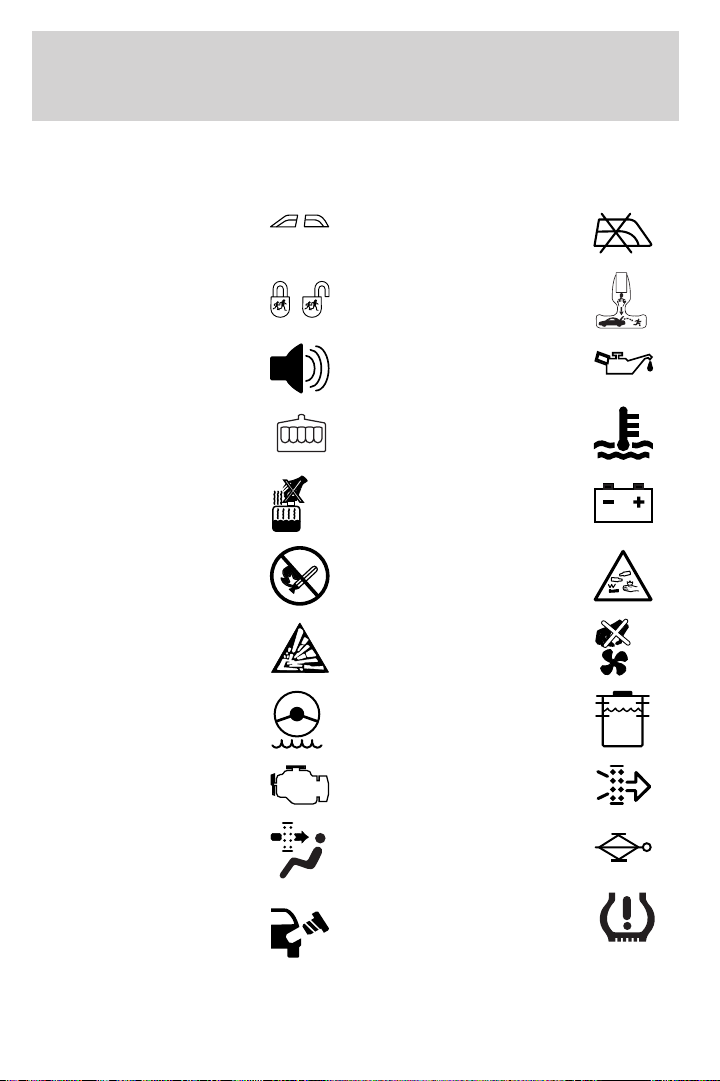
Vehicle Symbol Glossary
Introduction
Power Windows
Front/Rear
Child Safety Door
Lock/Unlock
Power Window Lockout
Interior Luggage
Compartment Release
Symbol
Panic Alarm Engine Oil
Engine Coolant
Engine Coolant
Temperature
Do Not Open When Hot Battery
Avoid Smoking, Flames,
or Sparks
Battery Acid
Explosive Gas Fan Warning
Power Steering Fluid
Maintain Correct Fluid
Level
Emission System Engine Air Filter
MAX
MIN
Passenger Compartment
Air Filter
Jack
Check fuel cap Low tire warning
11
Page 12
Instrument Cluster
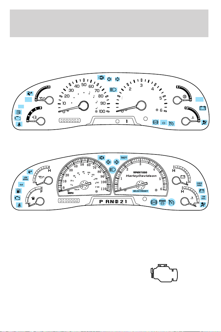
WARNING LIGHTS AND CHIMES
Standard instrument cluster
H
LOW
L
RANGE
4x4
F
E
Harley—Davidson instrument cluster
20
MPH
80
00
60
40
0
km/h
20
40
60
PRND2
THEFT
TRANS
TEMP
BRAKE
H
CHECK
GAGE
C
H
C
RPMX1000
SELECT
RESET
D
Warning lights and gauges can alert you to a vehicle condition that may
become serious enough to cause expensive repairs. A warning light may
illuminate when a problem exists with one of your vehicle’s functions.
Many lights will illuminate when you start your vehicle to make sure the
bulb works. If any light remains on after starting the vehicle, have the
respective system inspected immediately.
Service engine soon: The Service
engine soon indicator light
illuminates when the ignition is first
turned to the ON position to check
the bulb. Solid illumination after the engine is started indicates the On
Board Diagnostics System (OBD-II) has detected a malfunction. Refer to
On board diagnostics (OBD-II) in the Maintenance and Specifications
chapter. If the light is blinking, engine misfire is occurring which could
12
Page 13

Instrument Cluster
damage your catalytic converter. Drive in a moderate fashion (avoid
heavy acceleration and deceleration) and have your vehicle serviced
immediately.
Under engine misfire conditions, excessive exhaust temperatures
could damage the catalytic converter, the fuel system, interior
floor coverings or other vehicle components, possibly causing a fire.
Check fuel cap (if equipped):
Illuminates when the fuel cap may
not be properly installed. Continued
driving with this light on may cause
the Service engine soon warning
light to come on. Refer to Fuel
filler cap in the Maintenance and Specifications chapter.
Check gage: Illuminates when any
of the following conditions has
occurred:
• The engine coolant temperature
is high.
• The engine oil pressure is low.
• The fuel gauge is at or near empty.
Brake system warning light: To
confirm the brake system warning
light is functional, it will
momentarily illuminate when the
ignition is turned to the ON position when the engine is not running, or
in a position between ON and START, or by applying the parking brake
when the ignition is turned to the ON position. If the brake system
warning light does not illuminate at this time, seek service immediately
from your dealership. Illumination after releasing the parking brake
indicates low brake fluid level and the brake system should be inspected
immediately by your servicing dealership.
Driving a vehicle with the brake system warning light on is
dangerous. A significant decrease in braking performance may
occur. It will take you longer to stop the vehicle. Have the vehicle
checked by your dealer immediately.
CHECK
GAGE
13
Page 14
Instrument Cluster
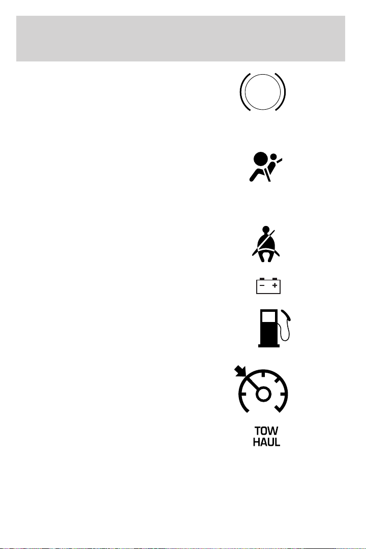
Anti-lock brake system: If the
ABS light stays illuminated or
continues to flash, a malfunction has
been detected, have the system
serviced immediately. Normal
braking is still functional unless the brake warning light also is
illuminated.
Air bag readiness: If this light fails
to illuminate when ignition is turned
to ON, continues to flash or remains
on, have the system serviced
immediately. A chime will also sound when a malfunction in the
supplemental restraint system has been detected.
Safety belt: Reminds you to fasten
your safety belt. A chime will also
sound to remind you to fasten your
safety belt.
Charging system: Illuminates when
the battery is not charging properly.
Low fuel: Illuminates when the fuel
level in the fuel tank is at or near
empty (refer to Fuel gauge in this
chapter).
ABS
Speed control: Illuminates when
the speed control is activated. Turns
off when the speed control system
is deactivated.
Transmission Tow/Haul Feature
(5R110W 5–speed automatic
transmission)
(if equipped-Diesel engines
only): Illuminates when the Tow/Haul feature has been activated. Refer
to the Driving chapter for transmission function and operation. If the
light flashes steadily, have the system serviced immediately, damage to
the transmission could occur.
14
Page 15

Instrument Cluster
Four wheel drive low (if
equipped): Illuminates when
four-wheel drive low is engaged.
Four wheel drive indicator (if
equipped): Illuminates when
four-wheel drive is engaged.
Anti-theft system (if equipped):
Flashes when the Securilock娂
Passive Anti-theft System has been
activated.
Door ajar: Illuminates when the
ignition is in the ON position and
any door is open.
Turn signal: Illuminates when the
left or right turn signal or the
hazard lights are turned on. If the
indicators stay on or flash faster, check for a burned out bulb.
High beams: Illuminates when the
high beam headlamps are turned on.
Key-in-ignition warning chime: Sounds when the key is left in the
ignition in the OFF/LOCK or ACCESSORY position and the driver’s door
is opened.
Headlamps on warning chime: Sounds when the headlamps or parking
lamps are on, the ignition is off (the key is not in the ignition) and the
driver’s door is opened.
Parking brake ON warning chime: Sounds when the parking brake is
set, the engine is running and the vehicle is driven more than 3 mph (5
Km).
LOW
RANGE
4x4
15
Page 16
Instrument Cluster
GAUGES
THEFT
H
LOW
L
RANGE
4x4
F
E
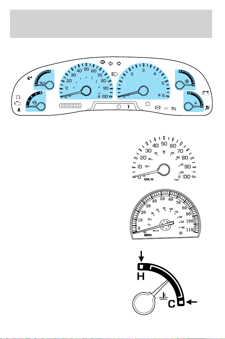
Speedometer: Indicates the current vehicle speed.
Standard instrument cluster
Harley—Davidson instrument
cluster
20
MPH
80
00
60
40
0
km/h
20
40
60
PRND2
RPMX1000
SELECT
RESET
D
BRAKE
TRANS
TEMP
H
CHECK
GAGE
C
H
C
Engine coolant temperature
gauge: Indicates engine coolant
temperature. At normal operating
temperature, the needle will be in
the normal range (between “H” and
“C”). If it enters the red section,
the engine is overheating. Stop
the vehicle as soon as safely
possible, switch off the engine
and let the engine cool.
16
Page 17
Instrument Cluster
Never remove the coolant reservoir cap while the engine is
running or hot.
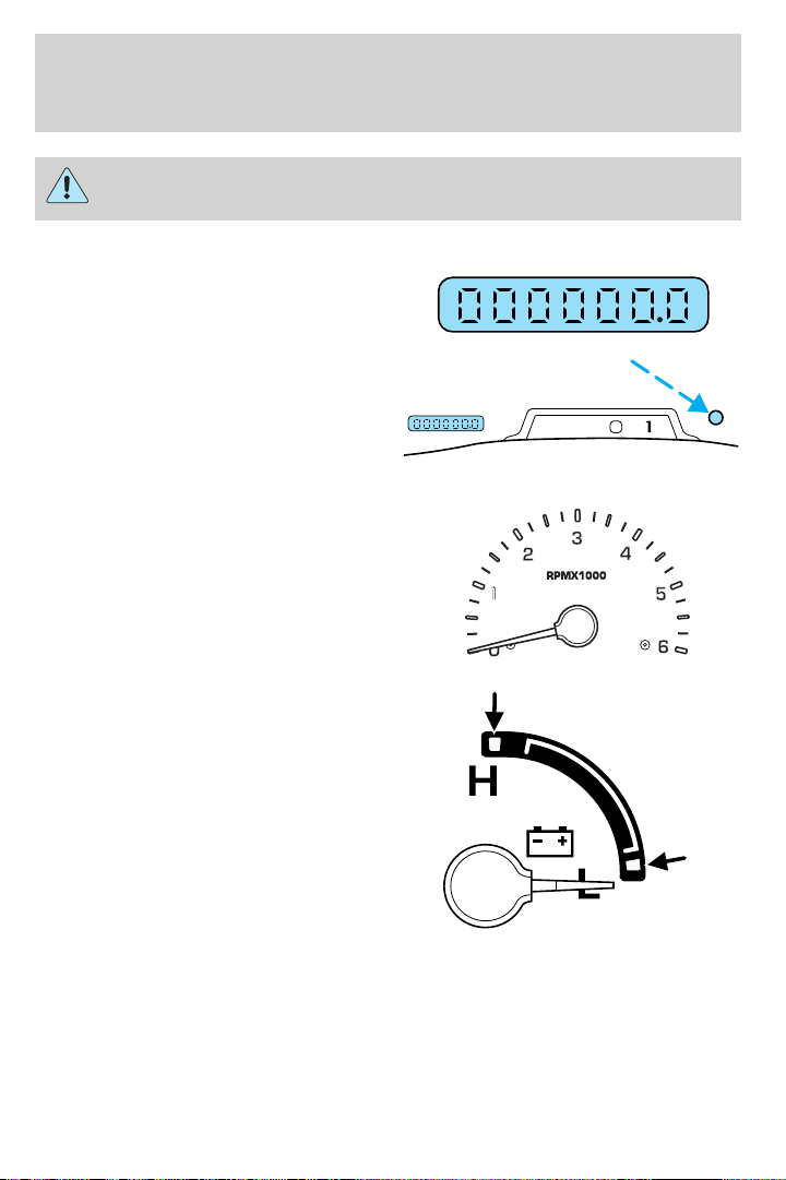
Odometer: Registers the total miles
(kilometers) of the vehicle.
Trip odometer: Registers the miles
(kilometers) of individual journeys.
Press the control once to switch
from the odometer to the trip
odometer. To reset the trip, press
the control again until the trip reading is 0.0 miles.
Tachometer: Indicates the engine
speed in revolutions per minute.
Driving with your tachometer
pointer continuously at the top of
the scale may damage the engine.
Battery voltage gauge (manual
transmission only): Indicates the
battery voltage when the ignition is
in the ON position. If the pointer
moves and stays outside the normal
operating range (as indicated by
arrows), have the vehicle’s electrical
system checked as soon as possible.
D
PRND2
17
Page 18
Instrument Cluster
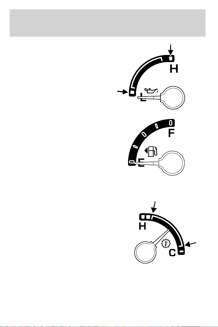
Engine oil pressure gauge:
Indicates engine oil pressure. The
needle should stay in the normal
operating range (between “L” and
“H”). If the needle falls below the
normal range, stop the vehicle, turn
off the engine and check the engine
oil level. Add oil if needed. If the oil
level is correct, have your vehicle
checked at your dealership or by a
qualified technician.
Fuel gauge: Indicates
approximately how much fuel is left
in the fuel tank (when the ignition
is in the ON position). The fuel
gauge may vary slightly when the
vehicle is in motion or on a grade.
Refer to Filling the tank in the
Maintenance and Specifications
chapter for more information.
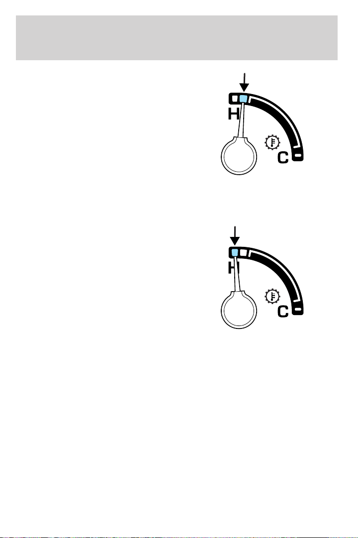
Transmission fluid temperature gauge (automatic transmission
only): If the gauge is in the:
White area (normal) - the
transmission fluid is within the
normal operating temperature
(between “H” and “C”).
18
Page 19
Instrument Cluster
Yellow area (warning) — the
transmission fluid is higher than
normal operating temperature. This
can be caused by special operation
conditions (i.e. snowplowing, towing
or off road use). Refer to Special
Operating Conditions in the
Scheduled Maintenance Guide for
instructions. Operating the
transmission for extended periods of
time with the gauge in the yellow
area may cause internal transmission damage.
Altering the severity of the driving conditions is recommended to lower
the transmission temperature into the normal range.
Red area (over temperature) —
the transmission fluid is overheating.
Stop the vehicle to allow the
temperature to return to normal
range.
If the gauge is operating in the Yellow or Red area, stop the vehicle and
verify the airflow is not restricted such as snow or debris blocking airflow
through the grill. If the gauge continues to show high temperatures, see
your Ford dealer.
19
Page 20
Entertainment Systems
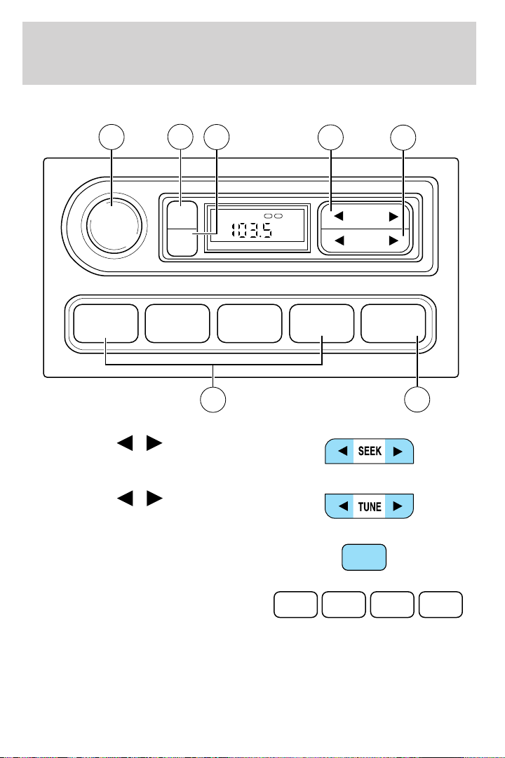
AM/FM STEREO (IF EQUIPPED)
VOL
PUSH
ON
6
TONE
CLK
7
5
1 2 3 4 AM/FM
4
1. Seek: Press
next strong station down/up the
frequency band.
2. Tune: Press
change radio frequency down/up.
/ to find the
/ to manually
TONE VOL
ST DX
1
FM
12
SEEK
TUNE
2
3
3. AM/FM: Press to choose a
frequency band in radio mode.
4. Memory preset buttons: To set
a station: Select frequency band
AM/FM; tune to a station, press and
hold a preset button until sound returns.
20
AM/FM
1 2 3 4
Page 21
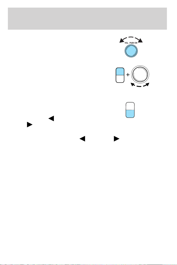
5. Power/volume: Press to turn
ON/OFF; turn to increase or
decrease volume levels.
Entertainment Systems
6. Tone: Press TONE until the
desired level — Bass, Treble, Fade
appears on the display. Turn the
volume control to raise/lower the
TONE
CLK
VOL
PUSH
ON
levels, or to move the audio sound
from the right to left or the front to
back (if equipped).
7. CLK (Clock): To set the hour,
press and hold CLK until CLOCK
SET appears in the display. Press
SEEK to decrease
increase
the hours.
or
TONE
CLK
To set the minute, press and hold CLK until CLOCK set appears in the
display. Press TUNE to decrease
or increase the minutes.
21
Page 22
Entertainment Systems
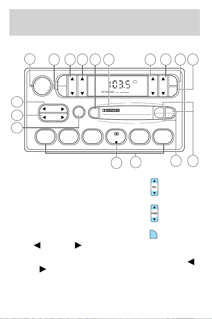
AM/FM STEREO CASSETTE (IF EQUIPPED)
12
VOL - PUSH ON
13 14 15 16 17 1 234
AM
BASS TREB BAL FADE
FM
11
10
SEEK
TUNE
SCAN
EJ
9
123456
1. Balance: Press to shift sound to
the left/right speakers.
2. Fade: Press to shift sound to the
rear/front speakers.
FM1
ST
8
7
SIDE
REW FF
CLK
TAPE
AMS
1 - 2
65
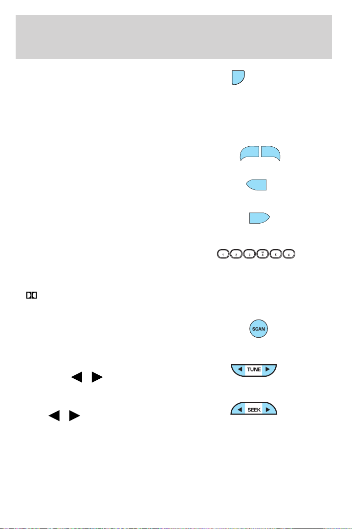
3. CLK: To set the hour, press and
hold CLK. Then press SEEK to
decrease
or increase the
CLK
hours.
To set the minute, press and hold CLK and press TUNE to decrease
or increase the minutes.
22
Page 23
Entertainment Systems
4. Tape AMS: In tape mode, press
and hold to activate Automatic
TAPE
AMS
Music Search (allows you to quickly
locate the beginning of the tape selection being played or to skip to the
next selection). Then, press REW (for the beginning of the current
selection) or FF (to advance to the next selection). The tape MUST have
a blank section of at least four seconds duration between programs.
5. Side 1–2: Press to change tape
SIDE 1 - 2
direction.
6. REW (rewind): Press to rewind
REW
the tape.
FF (fast forward): Press to
FF
advance the tape.
7. Memory preset buttons: To set
a station: Select frequency band
AM/FM1/FM2; tune to a station,
press and hold a preset button until sound returns.
Dolby威 noise reduction: Works in tape mode only. Reduces tape
8.
noise and hiss; press to activate/deactivate.
9. Scan: Press SCAN to hear a brief
sampling of all listenable radio
stations or all tape selections. Press
again to stop.
10. Tune: Works in radio mode only.
Press TUNE
/ to change
frequency down/up
11. Seek: Press and
release
/ for previous/next
strong station, selection or track.
23
Page 24
Entertainment Systems
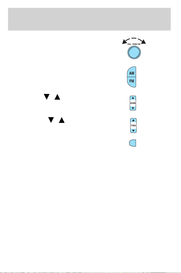
12. Power/volume: Press to turn
ON/OFF; turn to increase or
decrease volume levels.
13. AM/FM: Press to choose a
frequency band in radio mode.
14. Bass: Press
/ to
decrease/increase the bass output.
15. Treble: Press
/ to
decrease/increase the treble output.
16. EJ (Eject): Press to eject a
EJ
tape.
17. Cassette door: Insert a cassette into the cassette door.
24
Page 25
Entertainment Systems
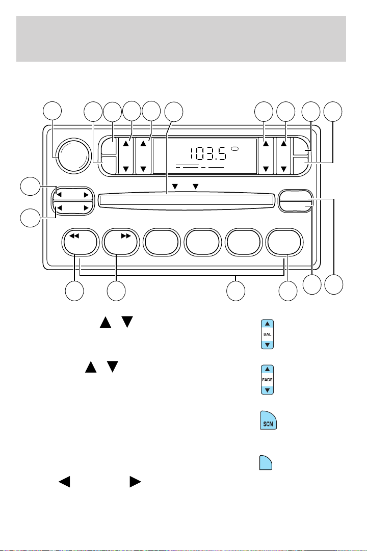
AM/FM STEREO / SINGLE CD RADIO (IF EQUIPPED)
12
13
VOL - PUSH ON
SEEK
TUNE
14
16 17
15
AM
FM
BASSCDTREB BAL FADE
11
CDCD
123456
1. Balance: Press
sound to the left/right speakers.
2. Fade: Press
sound to the front/rear speakers.
/ to shift
/ to shift
18
FM1
DISC
1 234
ST
COMP
SHUFFLE
8
7910
SCN
CLK
EJ
65
3. SCN (Scan): Press to hear a
brief sampling of all listenable
stations or CD tracks. Press again to
stop.
4. CLK: To set the hour, press and
hold CLK and press SEEK to
decrease
or increase the
hours.
CLK
25
Page 26
Entertainment Systems
To set the minute, press and hold CLK and press TUNE to decrease
or increase the minutes.
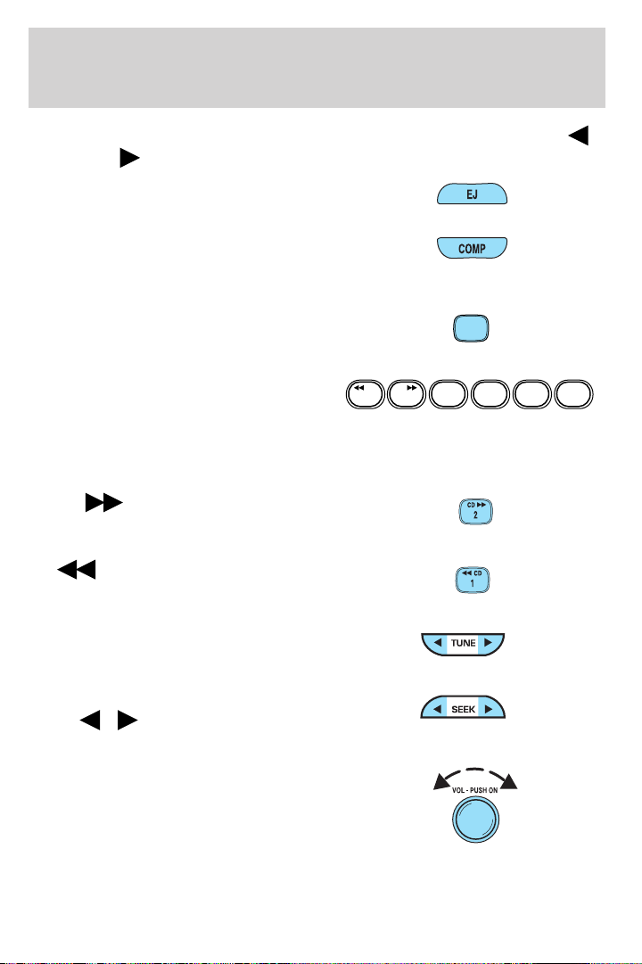
5. EJ (eject): Press to eject a CD.
6. COMP (Compression): In CD
mode, press to bring louder and
softer levels into more comfortable
listening level. The compression icon (c) will appear in the display.
7. Shuffle: Press to listen to the
tracks on the CD in random order.
Press again to turn off.
8. Memory presets: To set a
station: Select frequency band
CDCD
123456
AM/FM; tune to a station. Press and
hold a preset button until sound returns. This radio is equipped with six
station memory preset controls which allow you to set up to six AM
stations and 12 FM stations (six in FM1 and six in FM2).
9. CD:
Press and hold until
desired point of a selection is
reached.
10.
CD: Press and hold until
desired point of a selection is
reached.
11. Tune: In radio mode, press to
move up or down the frequency
band in individual increments.
12. Seek: Press and release
SEEK
/ for previous/next
strong station, selection or track.
13. Power/volume: Press to turn
ON/OFF; turn to increase or
decrease volume levels.
SHUFFLE
6
SHUFFLE
26
Page 27
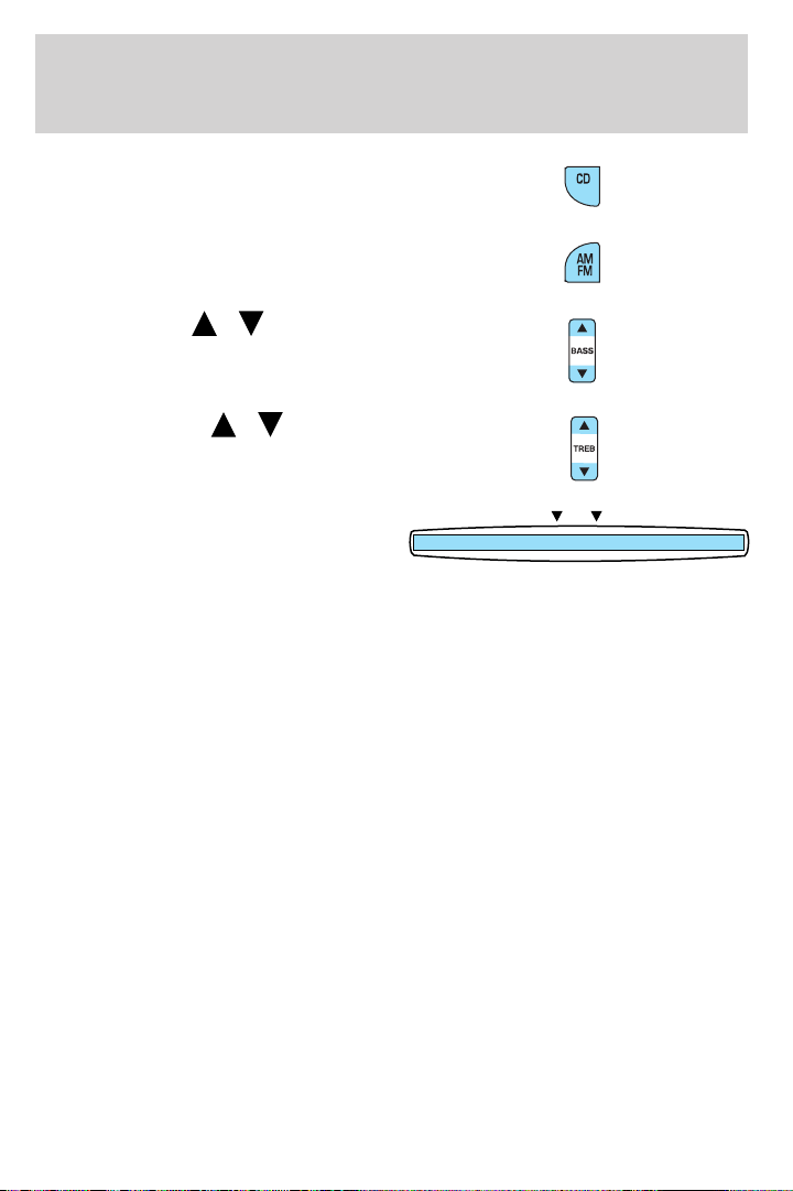
14. CD: Press to enter CD mode or
to play a CD already loaded into the
system.
15. AM/FM: Press to choose a
frequency band in radio mode.
Entertainment Systems
16. Bass: Press
/ to
increase/decrease the bass output.
17. Treble: Press
/ to
increase/decrease the treble output.
18. CD slot: Insert a CD printed
DISC
side up.
CD units are designed to play
commercially pressed 4.75 in (12 cm) audio compact discs only.
Due to technical incompatibility, certain recordable and
re-recordable compact discs may not function correctly when
used in Ford CD players. Irregular shaped CDs, CDs with a
scratch protection film attached, and CDs with homemade paper
(adhesive) labels should not be inserted into the CD player. The
label may peel and cause the CD to become jammed. It is
recommended that homemade CDs be identified with permanent
felt tip marker rather than adhesive labels. Ballpoint pens may
damage CDs. Please contact your dealer for further information.
27
Page 28
Entertainment Systems
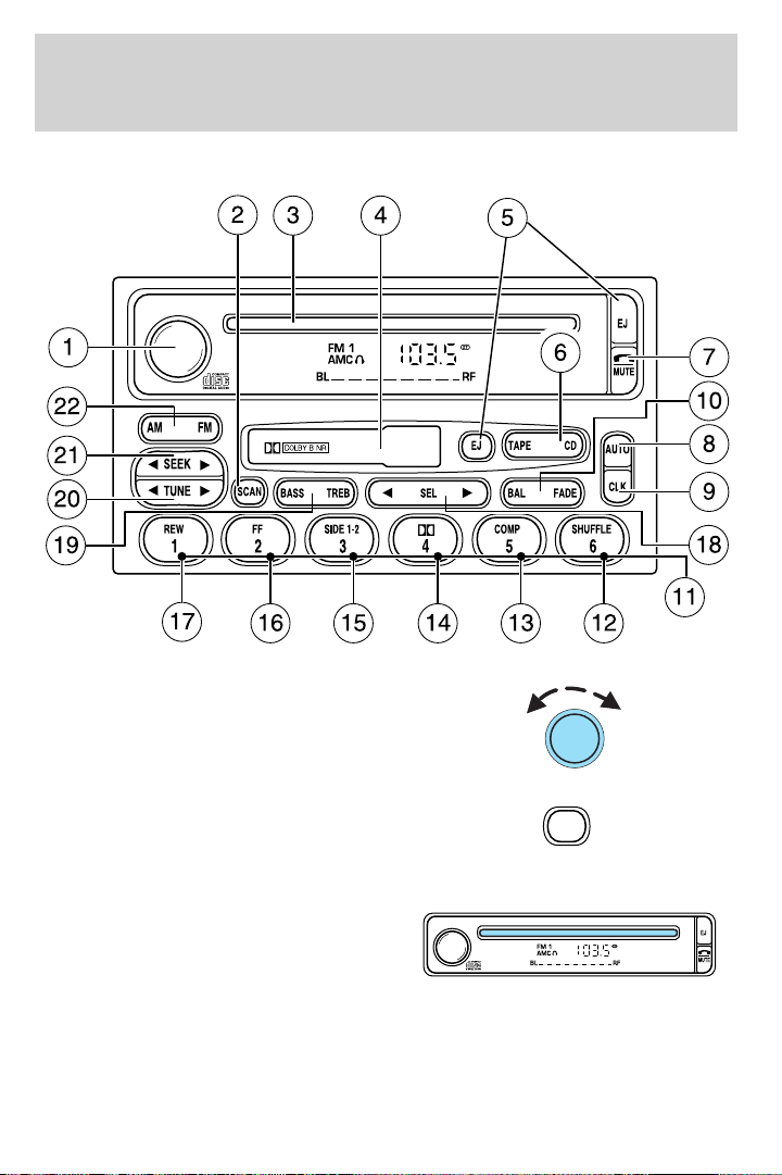
PREMIUM AM/FM STEREO/CASSETTE/SINGLE CD (IF EQUIPPED)
1. Power/volume: Press to turn
ON/OFF; turn to increase/decrease
volume.
2. Scan: Press to hear a brief
sampling of all listenable stations,
tape selections or CD tracks. Press
again to stop.
3. CD slot: Insert a CD with the
label side up.
CD units are designed to play
commercially pressed 4.75 in
(12 cm) audio compact discs only. Due to technical
incompatibility, certain recordable and re-recordable compact
discs may not function correctly when used in Ford CD players.
Irregular shaped CDs, CDs with a scratch protection film
attached, and CDs with homemade paper (adhesive) labels should
28
SCAN
Page 29
Entertainment Systems
not be inserted into the CD player. The label may peel and cause
the CD to become jammed. It is recommended that homemade
CDs be identified with permanent felt tip marker rather than
adhesive labels. Ballpoint pens may damage CDs. Please contact
your dealer for further information.
4. Cassette door: Insert the
cassette with the opening to the
right.
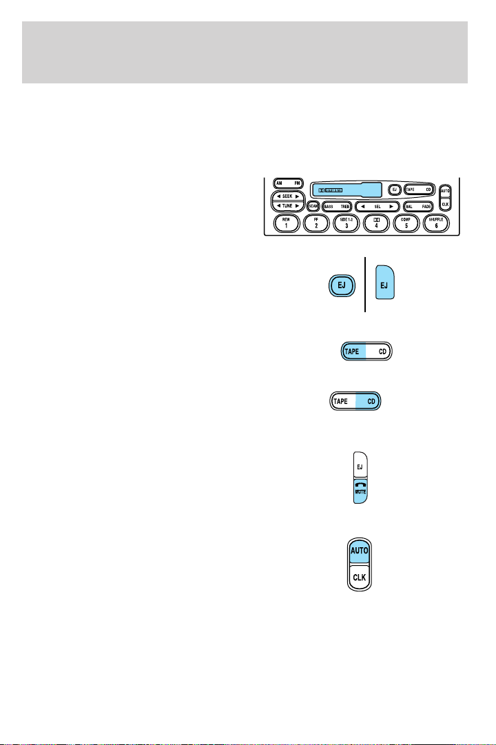
5. Eject: Press to eject the
cassette/CD. The radio will resume
playing.
6. Tape: Press to start tape play.
Press to stop tape during
rewind/fast forward.
CD: Press to start CD play. With the
dual media audio, press CD to
toggle between single CD and CD
changer play (if equipped).
7. Mute: Press to MUTE playing
media; press again to return to the
playing media.
8. Auto: Press to set first six
strongest stations (if available) into
AM, FM1 or FM2 memory buttons;
press again to return to normal
stations.
29
Page 30
Entertainment Systems
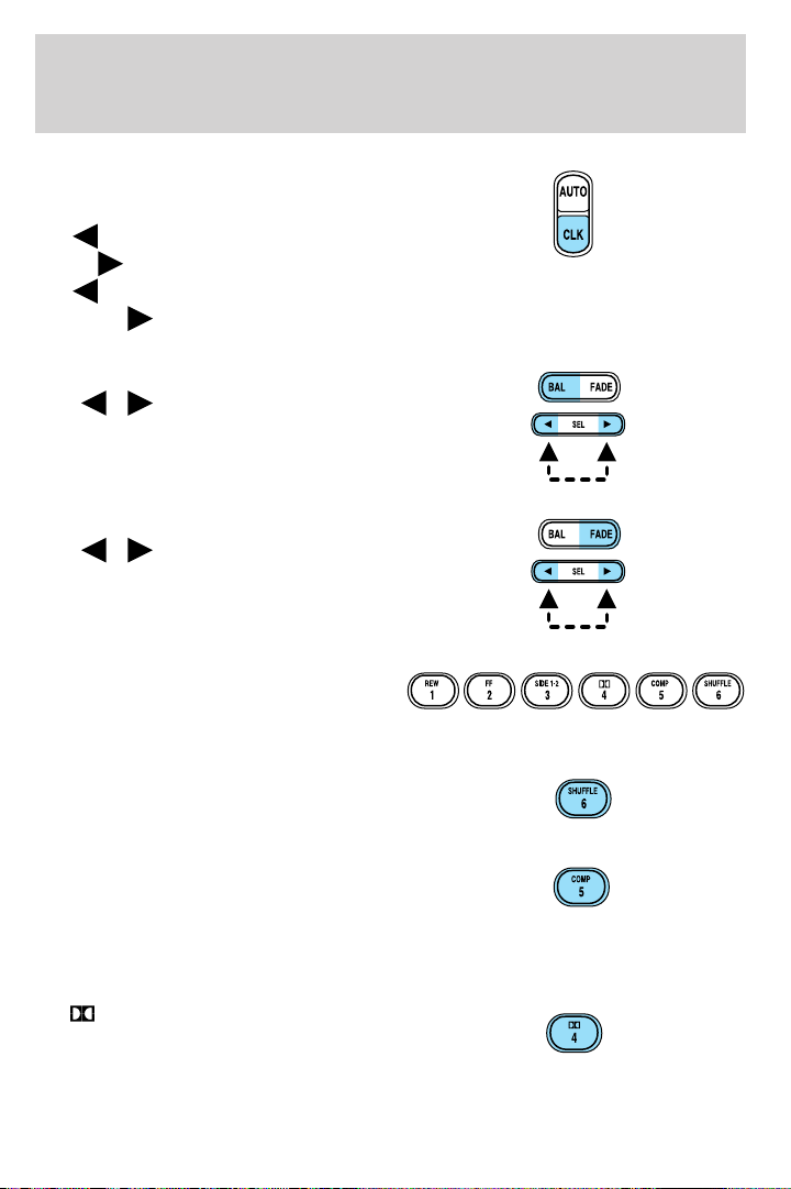
9. Clock: Press to toggle between
station mode and clock mode. Press
and hold to set the clock. Press
the
SEEK
the TUNE to decrease minutes
or TUNE
this control will not function.
10. Balance: Press BAL; then press
SEL
left/right speakers.
Fade: Press FADE; then press
SEL
rear/front speakers.
11. Memory preset buttons: To
set a station: Select frequency band
AM/FM, tune to a station, press and
hold a preset button until sound returns.
12. Shuffle (CD): Press to play
tracks in random order. Press again
to disable.
SEEK to decrease hours or
to increase hours. Press
to increase minutes. If your vehicle has a stand alone clock
/ to shift sound to the
/ to shift sound to the
13. Compression (CD): Press to
bring soft and loud passages
together for a more consistent
listening level. A small “c” will
appear in the display to indicate that compression is enabled. Press again
to disable.
14.
Works in tape mode only. Reduces
tape noise and hiss; press to
activate/deactivate.
30
Dolby威 noise reduction:
Page 31
Entertainment Systems
The Dolby威 noise reduction system is manufactured under license from
Dolby Laboratories Licensing Corporation. Dolby威 and the double-D
symbol are registered trademarks of Dolby Laboratories Licensing
Corporation.
15. Side 1–2: Works in tape mode
only. Press to play reverse side of
the tape.
16. Fast Forward (FF): In CD
mode, press for a slow advance,
FF
2
press and hold for a fast advance. In
TAPE mode, press FF to enable
Fast Forward feature. Press FF or TAPE to resume tape play.
17. Rewind (REW): In CD mode,
press for a slow reverse, press and
REW
1
hold for a fast reverse. In TAPE
mode, press REW to enable the
rewind feature. Press REW or TAPE to resume tape play.
18. Select (SEL): Use with Bass,
Treble, Balance and Fade controls.
SEL
19. Bass: Press BASS; then press
SEL
/ to decrease/increase
the bass output.
Treble: Press TREB; then press
SEL
/ to decrease/increase
the treble output.
20. Tune: Works in radio mode only.
Press TUNE
/ to change
SEEK
TUNE
frequency down/up.
31
Page 32
Entertainment Systems
21. Seek: Press and release
SEEK
strong station, selection or track.
22. AM/FM: Press to select
AM/FM1/FM2 frequency band.
PREMIUM IN-DASH SIX CD SOUND SYSTEM (IF EQUIPPED)
/ for previous/next
SEEK
TUNE
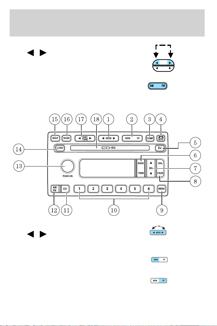
1. Seek: Press and release
SEEK
/ for previous/next
strong station, or track of current
disc.
2. Rewind: Press for a slow rewind,
press and hold for a fast rewind.
Fast forward: Press for a slow
advance, press and hold for a fast
advance.
32
Page 33
Entertainment Systems
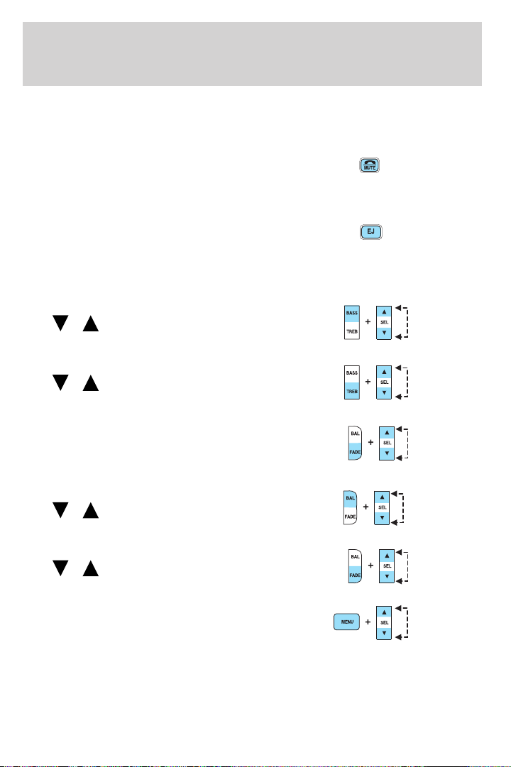
3. Comp (Compression): In CD mode, press to adjust the soft and loud
passages together for a more consistent listening level. Press the COMP
control until COMP ON is displayed.
4. Mute: Press to MUTE playing
media; press again return to playing
media. In CD mode, MUTE acts as a
pause feature.
5. Eject: Press to eject a CD.
EJECTING # (desired selection) will
appear on the display. When the CD
appears in the CD slot for removal, the display reads REMOVE CD #
(desired selection). Press and hold to eject all loaded discs.
6. Bass: Press BASS; then press
SEL
the bass output.
Treble: Press TREB; then press
SEL
the treble output.
7. Select: Use with Bass, Treble,
Balance and Fade controls to adjust
levels. Use with MENU to set the
clock and engage RDS.
8. Balance: Press BAL; then press
SEL
left/right speakers.
Fade: Press FADE; then press
SEL
rear/front speakers.
9. Menu: Press MENU and SEL to
access clock mode, RDS on/off,
Traffic, Program type, Show type
and Compression modes.
Traffic: Allows you to hear traffic broadcasts. With the feature ON, press
SEEK or SCAN to find a station broadcasting a traffic report (if it is
broadcasting RDS data). Traffic information is not available in most
U.S. markets.
/ to decrease/increase
/ to decrease/increase
/ to shift sound to the
/ to shift sound to the
33
Page 34
Entertainment Systems
FIND Program type: Allows you to search RDS-equipped stations for a
certain category of music format: Classic, Country, Info, Jazz, Oldies,
R&B, Religious, Rock, Soft, Top 40.
Show TYPE: Displays the station’s call letters and format.
Compression: In CD mode, press to bring soft and loud CD passages
together for a more consistent listening level.
Setting the clock: Press MENU until SELECT HOUR or SELECT MINS
is displayed. Use SEL to manually increase (
hours/minutes. Press MENU again to disengage clock mode.
10. Memory presets: To set a
station: Select frequency band
AM/FM; tune to a station, press and
hold a preset button until sound
returns. In CD mode, press to move between CDs.
This radio is equipped with six station memory preset controls which
allow you to set up to six AM stations and 12 FM stations (six in FM1
and six in FM2).
11. CD: Press to select CD mode.
Seamless play: In CD mode, the
transition between the end of one
CD and the beginning of another will not contain delay time unless SEEK
or a preset control is pressed.
12. AM/FM: Press to select a
frequency band in radio mode.
Autoset: Allows you to set the
strongest local radio stations without losing your original manually set
preset stations for AM/FM1/FM2 . Press and momentarily hold AM/FM.
AUTOSET will flash on the display. When the six strongest stations are
filled, the station stored in preset 1 will begin playing. If there are less
than six strong stations, the system will store the last one in the
remaining presets. Press again to disengage.
13. Power/volume: Press to turn
ON/OFF; turn to increase or
decrease volume levels.
) or decrease ( ) the
34
Page 35
Entertainment Systems
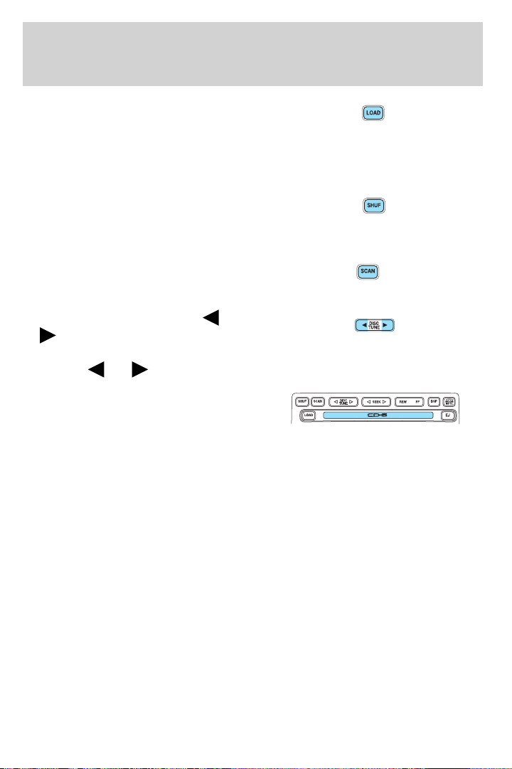
14. Load: Press to load a CD.
SELECT SLOT will appear in the
display. Select from 1–6onthe
memory presets. MOVING TO # and then LOAD CD# will appear in the
display. Insert the CD into the system, label side up. Press and hold to
load up to six discs.
15. Shuffle: In CD mode, press to
play tracks in random order. Press
SHUF to cycle through SHUF TRAC,
SHUF DISC or SHUF OFF.
16. Scan: Press to hear a brief
sampling of all listenable stations or
CD tracks. Press again to stop.
17. Disc/Tune: Radio: Press
or to manually tune down or up
the frequency band.
CD: Press
18. CD door: Insert a CD label side
up.
RADIO FREQUENCIES
AM and FM frequencies are established by the Federal Communications
Commission (FCC) and the Canadian Radio and Telecommunications
Commission (CRTC). Those frequencies are:
AM - 530, 540–1700, 1710 kHz
FM- 87.7, 87.9–107.7, 107.9 MHz
or to select the previous or next CD.
RADIO RECEPTION FACTORS
There are three factors that can affect radio reception:
• Distance/strength: The further you travel from an FM station, the
weaker the signal and the weaker the reception.
• Terrain: Hills, mountains, tall buildings, power lines, electric fences,
traffic lights and thunderstorms can interfere with your reception.
• Station overload: When you pass a broadcast tower, a stronger signal
may overtake a weaker one and play while the weak station frequency
is displayed.
35
Page 36

Entertainment Systems
CASSETTE/PLAYER CARE
Do:
• Use only cassettes that are 90 minutes long or less.
• Tighten very loose tapes by inserting a finger or pencil into the hole
and turning the hub.
• Remove loose labels before inserting tapes.
• Allow tapes which have been subjected to extreme heat, humidity or
cold to reach a moderate temperature before playing.
• Clean the cassette player head with a cassette cleaning cartridge after
10–12 hours of play to maintain good sound/operation.
Don’t:
• Expose tapes to direct sunlight, extreme humidity, heat or cold.
• Leave tapes in the cassette player for a long time when not being
played.
CD/CD PLAYER CARE
Do:
• Handle discs by their edges only. Never touch the playing surface.
• Inspect discs before playing. Clean only with an approved CD cleaner
and wipe from the center out.
Don’t:
• Expose discs to direct sunlight or heat sources for extended periods
of time.
• Insert more than one disc into each slot of the CD changer magazine.
• Clean using a circular motion.
CD units are designed to play commercially pressed 12 cm (4.75
in) audio compact discs only. Due to technical incompatibility,
certain recordable and re-recordable compact discs may not
function correctly when used in Ford CD players. Irregular
shaped CDs, CDs with a scratch protection film attached, and CDs
with homemade paper (adhesive) labels should not be inserted
into the CD player. The label may peel and cause the CD to
become jammed. It is recommended that homemade CDs be
identified with permanent felt tip marker rather than adhesive
labels. Ball point pens may damage CDs. Please contact your
dealer for further information.
36
Page 37

Entertainment Systems
AUDIO SYSTEM WARRANTY AND SERVICE
Refer to the Warranty Guide for audio system warranty information. If
service is necessary, see your dealer or qualified technician.
37
Page 38
Climate Controls
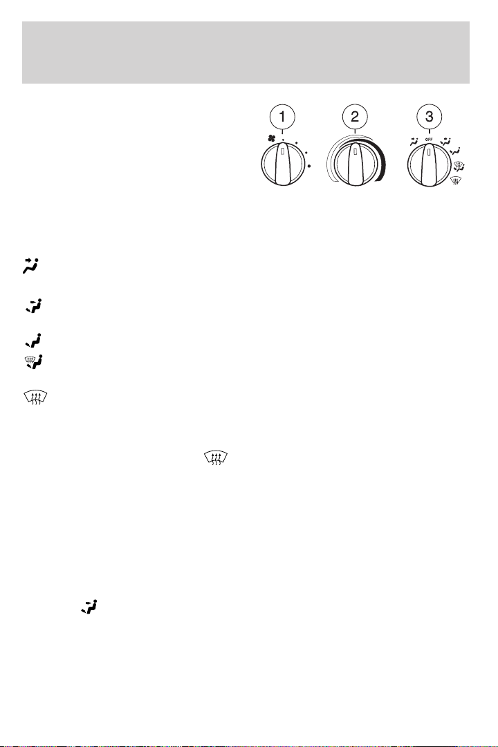
HEATER ONLY SYSTEM
(IF EQUIPPED)
1. Fan speed adjustment: Controls
the volume of air circulated in the
vehicle.
2. Temperature selection:
Controls the temperature of the
airflow in the vehicle.
3. Air flow selections: Controls the direction of the airflow in the
vehicle. See the following for a brief description on each control:
: Distributes outside air through the instrument panel vents.
OFF: Outside air is shut out and the fan will not operate.
: Distributes outside air through the instrument panel vents and the
floor vents.
: Distributes outside air through the floor vents.
: Distributes outside air through the windshield defroster vents and
floor vents.
: Distributes outside air through the windshield defroster vents.
Operating tips
• To reduce fog build up on the windshield during humid weather, place
the air flow selector in the
• To reduce humidity build up inside the vehicle during cold or warm
weather, do not drive or leave the vehicle parked with the air flow
selector in the OFF position.
• Do not put objects under the front seats that will interfere with the air
flow to the rear seats.
• Remove any snow, ice or leaves from the air intake area at the base of
the windshield.
To aid in side window defogging/demisting in cold weather:
1. Select
2. Modulate the temperature control to maintain comfort.
3. Set the fan speed to the highest setting.
4. Direct the outer instrument panel vents toward the side windows.
To increase airflow to the outer instrument panel vents, close the vents
located in the middle of the instrument panel.
.
position.
38
Page 39
Climate Controls
Do not place objects on top of the instrument panel as these
objects may become projectiles in a collision or sudden stop.
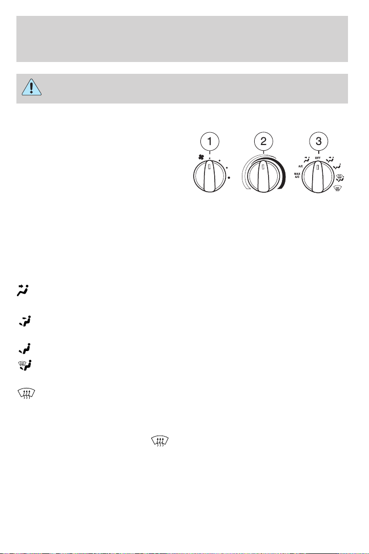
MANUAL HEATING AND AIR CONDITIONING SYSTEM
(IF EQUIPPED)
1. Fan speed adjustment: Controls
the volume of air circulated in the
vehicle.
2. Temperature selection:
Controls the temperature of the
airflow in the vehicle.
3. Air flow selections: Controls the direction of the airflow in the
vehicle. See the following for a brief description on each control.
MAX A/C: Uses recirculated air to cool the vehicle. Air flows from the
instrument panel vents only.
A/C: Uses outside air to cool the vehicle. Air flows from the instrument
panel vents only.
: Distributes outside air through the instrument panel vents.
OFF: Outside air is shut out and the fan will not operate.
: Distributes outside air through the instrument panel vents and the
floor vents.
: Distributes outside air through the floor vents.
: Distributes outside air through the windshield defroster vents and
floor vents.
: Distributes outside air through the windshield defroster vents.
Operating tips
• To reduce fog build up on the windshield during humid weather, place
the air flow selector in the
• To reduce humidity build up inside the vehicle, do not drive with the
air flow selector in the OFF or with recirculated air engaged.
• Do not put objects under the front seats that will interfere with the
airflow to the rear seats.
• Remove any snow, ice or leaves from the air intake area at the base of
the windshield.
position.
39
Page 40
Climate Controls
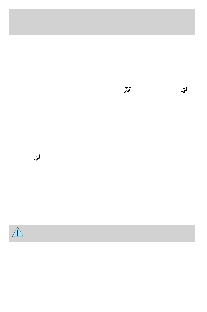
• To improve the A/C cool down, drive with the windows slightly open
for 2–3 minutes after start up or until the vehicle has been “aired out.”
For maximum cooling performance (MAX A/C) in MAX A/C mode:
• Move the temperature control to the coolest setting.
• Set the fan to the highest speed initially, then adjust in order to
maintain comfort.
For maximum cooling performance in panel (
modes:
• Move the temperature control to the coolest setting.
• Select A/C and recirculated air . Use recirculated air with A/C to
provide a cooler airflow.
• Set the fan to the highest speed initially, then adjust in order to
maintain comfort.
To allow side window defogging and demisting while warming up the
vehicle cabin:
1. Select
2. Select A/C.
3. Set the temperature control to maintain comfort.
4. Set the fan speed to highest setting.
5. Direct the outer instrument panel vents towards the side windows. To
increase airflow to the outer instrument panel vents, close the vents
located in the middle of the instrument panel.
To increase airflow to the outer instrument panel vents, close the vents
located in the middle of the instrument panel.
.
) and panel/floor ( )
40
Do not place objects on top of the instrument panel as these
objects may become projectiles in a collision or sudden stop.
Page 41
Lights
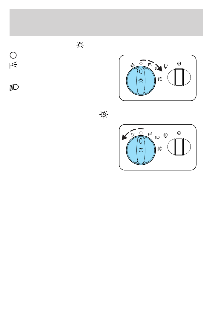
HEADLAMP CONTROL
Turns the lamps off.
Turns on the parking lamps,
instrument panel lamps, license
plate lamps and tail lamps.
Turns the headlamps on.
Autolamp control (if equipped)
The autolamp system provides light
sensitive automatic on-off control of
the exterior lights normally
controlled by the headlamp control.
The autolamp system also keeps the
lights on for approximately 20
seconds after the ignition switch is
turned to OFF.
To change the delay time of the
autolamp feature, do the following:
1. Start with the ignition in OFF and the autolamps selected.
2. Deselect the autolamps.
3. Put the ignition in RUN.
4. Put the ignition in OFF.
5. Select the autolamps. Steps 2 through 5 must be performed within a
10 second period. At this point, the headlamps and parking lamps will
turn on.
6. Deselect the autolamps after the desired autolamp delay time
(maximum of 3 minutes). At this point, the headlamps and parking
lamps will turn off.
A
A
41
Page 42
Lights
Foglamp control (if equipped)
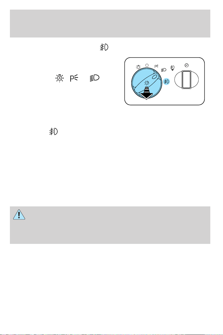
The headlamp control also operates
the foglamps. The foglamps can be
turned on only when the headlamp
control is in the
, or
position and the high beams are not
turned on.
In autolamp mode, the foglamps
won’t be operational until lighting
conditions warrant the activation of the headlamp/parklamp lighting.
Pull headlamp control towards you to turn foglamps on. The foglamp
indicator light
will illuminate when the switch is pulled and the
parklamps are on.
Daytime running lamps (DRL) (if equipped)
Turns the headlamps on with a reduced output.
To activate:
• the ignition must be in the ON position,
• the headlamp control is in the OFF or parking lamp position and
• the parking brake must be disengaged.
Always remember to turn on your headlamps at dusk or during
inclement weather. The Daytime Running Lamp (DRL) system
does not activate with your tail lamps and generally may not provide
adequate lighting during these conditions. Failure to activate your
headlamps under these conditions may result in a collision.
A
42
Page 43
High beams
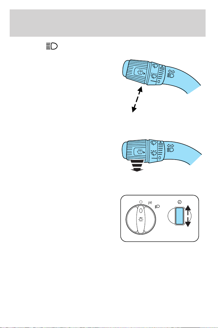
Push the lever toward the
instrument panel to activate. Pull
the lever towards you to deactivate.
Flash to pass
Pull toward you slightly to activate
and release to deactivate.
PANEL DIMMER CONTROL
Use to adjust the brightness of the
instrument panel and all applicable
switches in the vehicle during
headlamp and parklamp operation.
Move the control to the full upright
position, past detent, to turn on the
interior lamps.
Lights
AIMING THE HEADLAMPS
The headlamps on your vehicle are properly aimed at the assembly plant.
If your vehicle has been in an accident the alignment of your headlamps
should be checked by a qualified service technician.
43
Page 44
Lights
TURN SIGNAL CONTROL
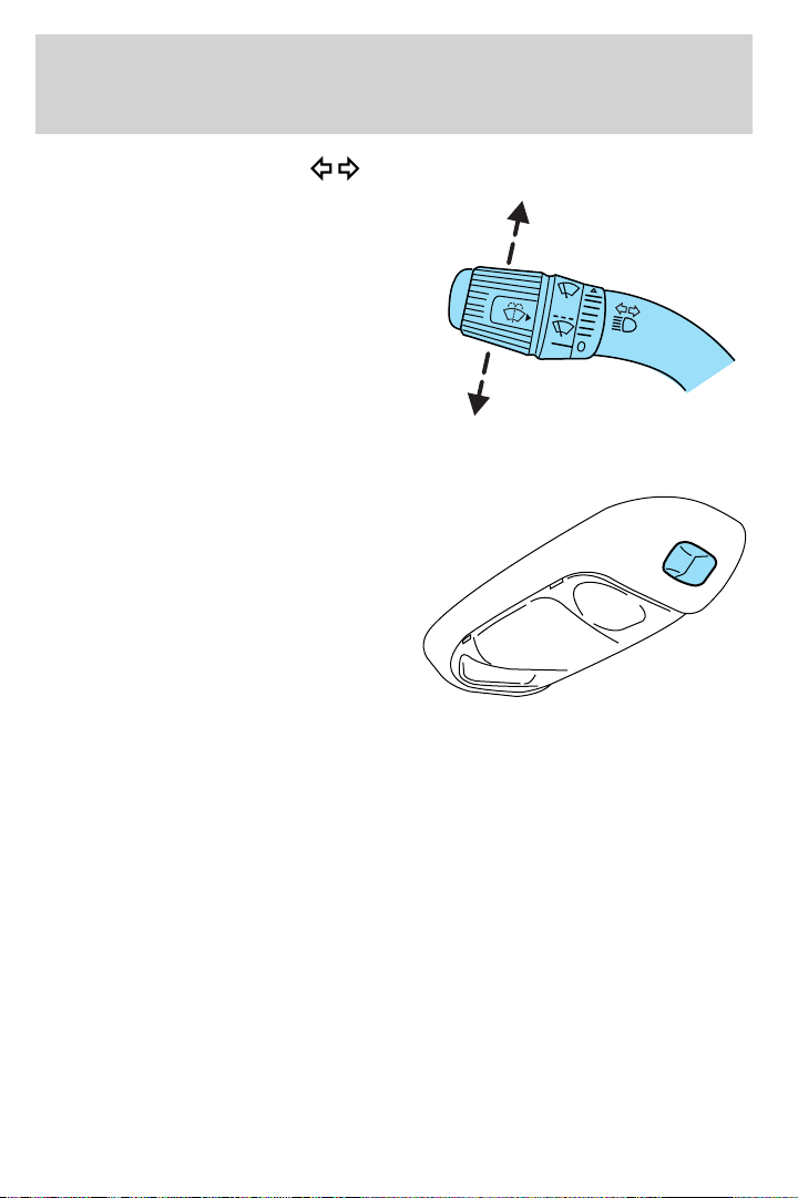
• Push down to activate the left
turn signal.
• Push up to activate the right turn
signal.
COURTESY/READING LAMPS (IF EQUIPPED)
The dome lamp lights when any
door is not completely closed, the
instrument panel switch is pushed
past the detent and when any of the
remote entry controls are pressed
while the ignition is off.
The reading lamps can be turned on
by pressing the rocker controls next
to each lamp.
44
Page 45
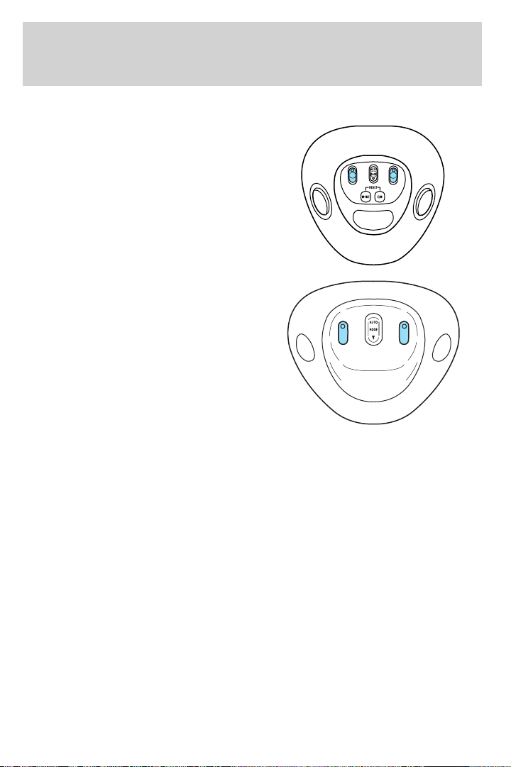
MAP LAMPS (IF EQUIPPED)
With trip computer
Without trip computer
To turn on the map lamps, press the control next to each lamp.
BULBS
Lights
Replacing exterior bulbs
Check the operation of all the bulbs frequently.
Using the right bulbs
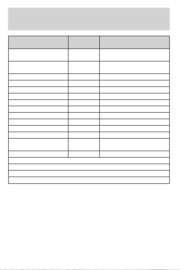
Replacement bulbs are specified in the chart below. Headlamp bulbs
must be marked with an authorized “D.O.T.” for North America and an
“E” for Europe to assure lamp performance, light brightness and pattern
and safe visibility. The correct bulbs will not damage the lamp assembly
or void the lamp assembly warranty and will provide quality bulb burn
time.
45
Page 46
Lights
Function Number of
Trade number
bulbs
Headlamps
2 9007
(aerodynamic)
Headlamps (sealed
2 H6054
beam)
Park/turn 2 3157 AK
Sidemarker 2 194
Tail/stop/turn/sidemarker 2 3157 K
Backup 2 3156K
High-mount stoplamp 1 922
Foglamp 2 9145
License plate lamp 2 194
Cargo lamp 2 906
Roofmarker 5 194
Rear fender clearance* 4
Interior visor lamp (if
4 194
(a)
equipped)
Rear identification 3 194
All replacement bulbs are clear in color except where noted.
To replace all instrument panel lights - see your dealer
* Dual rear wheels or if equipped.
(a)
Replace entire lamp assembly; bulb is not serviceable.
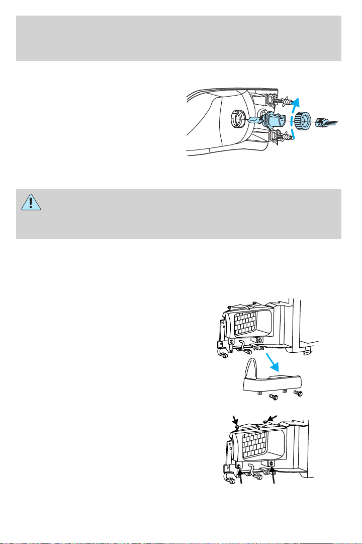
Replacing headlamp bulbs (aerodynamic)
1. Make sure that the headlamp control is in the OFF position and open
the hood.
2. Disconnect the electrical connector from the bulb by pulling rearward.
46
Page 47
Lights
3. Remove bulb retainer ring by
turning it counterclockwise, then
slide the ring off the plastic base.
4. Pull bulb out of headlamp
assembly.
Handle a halogen headlamp bulb carefully and keep out of
children’s reach. Grasp the bulb only by its plastic base and do
not touch the glass. The oil from your hand could cause the bulb to
break the next time the headlamps are operated.
Install the new bulb(s) in reverse order.
Replacing headlamp bulbs (sealed beam)
1. Make sure headlamp switch is in OFF position and open the hood.
2. Remove the two screws and the
parking lamp/side marker assembly
by pulling gently.
3. Disconnect the electrical
connectors from the parking
lamp/side marker assembly and
remove.
4. Remove the four bolts and
headlamp bezel.
47
Page 48
Lights
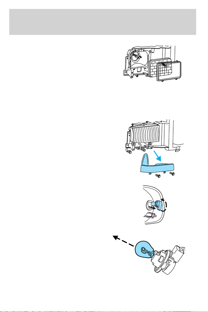
5. Remove the four screws and the
headlamp retaining ring from
headlamp.
6. Disconnect the electrical
connector and remove headlamp.
Install the new bulb(s) in reverse order.
Replacing front parking/turn signal bulbs
1. Make sure headlamp switch is in OFF position and open the hood.
2. Remove the two screws and
carefully disengage parking
lamp/turn signal assembly from the
vehicle.
3. Disconnect the electrical
connectors from the parking
lamp/side marker assembly and
remove.
4. Rotate bulb socket
counterclockwise and remove from
lamp assembly.
5. Carefully pull bulb straight out of
the socket and push in the new
bulb.
Install the new bulb(s) in reverse order.
48
Page 49
Lights
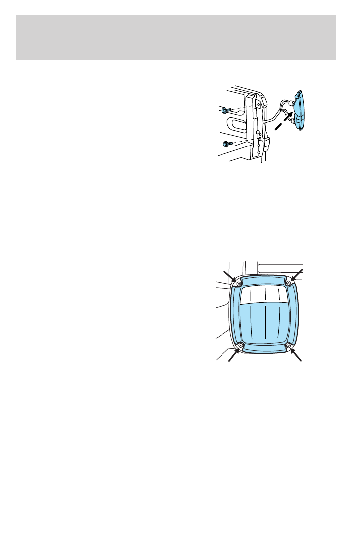
Replacing tail lamp/turn/backup lamp bulbs — F250/F350 only
1. Make sure the headlamp switch is
in the OFF position and then open
the tailgate to expose the lamp
assemblies.
2. Remove the two bolts from the
tail lamp assembly and carefully pull
the lamp assembly from the tailgate
pillar by releasing the two retaining
tabs.
3. Rotate the bulb socket counterclockwise and remove from lamp
assembly.
4. Pull the bulb straight out of the socket.
Install the new bulb(s) in reverse order.
Replacing brake/tail/backup lamp bulbs — F450/F550 only
1. Make sure the headlamp switch is
in the OFF position.
2. Remove the four screws and the
lamp lens from lamp assembly.
3. Carefully pull the bulb straight
out of the socket and push in the
new bulb.
49
Page 50
Lights
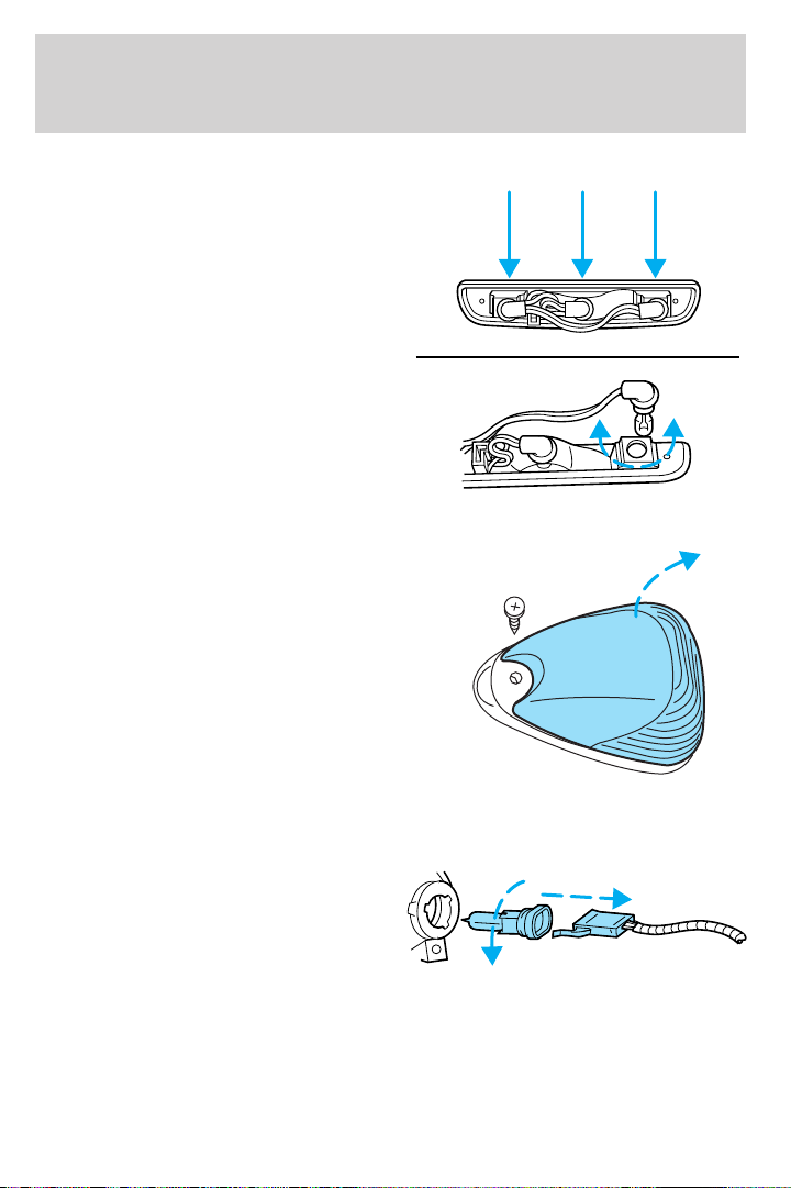
Replacing cargo lamp and high-mount brakelamp bulbs
1. Make sure the headlamp switch is
in the OFF position.
2. Remove the two screws and lamp
assembly from vehicle as wiring
permits.
3. Remove the bulb socket by
rotating counterclockwise.
4. Pull the bulb straight out of the
socket.
Replacing roof marker bulbs
1. Make sure the headlamp switch is
in the OFF position.
2. Remove the screw and lens from
the lamp assembly.
3. Pull the bulb straight out of the
socket.
Install the bulb(s) in reverse order.
Replacing foglamp bulbs (if equipped)
1. Make sure the headlamp switch is
in the OFF position.
2. Remove the bulb socket from the
foglamp by turning
counterclockwise.
3. Disconnect the electrical connector from the foglamp bulb.
Install the new bulb(s) in reverse order.
50
Page 51
Lights
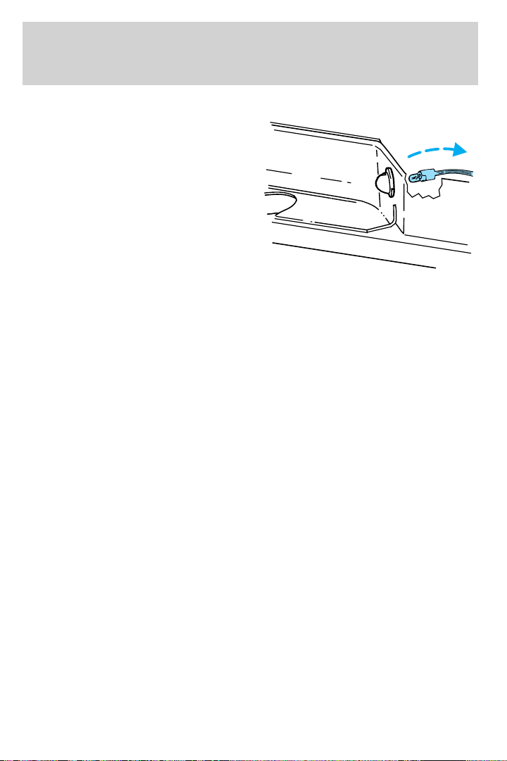
Replacing license plate lamp bulbs
The license plate bulbs are located
behind the rear bumper. To change
the license plate lamp bulbs:
1. Reach behind the rear bumper to
locate the bulb.
2. Twist the bulb socket
counterclockwise and carefully pull
to remove it from the lamp
assembly.
3. Pull out the old bulb from the
socket and push in the new bulb.
4. Install the bulb socket in lamp assembly by turning it clockwise.
51
Page 52
Driver Controls
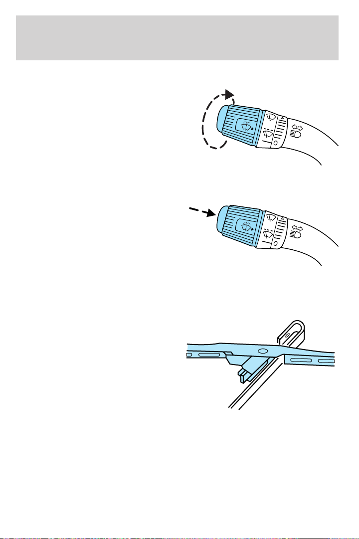
MULTI-FUNCTION LEVER
Windshield wiper: Rotate the end
of the control away from you to
increase the speed of the wipers;
rotate towards you to decrease the
speed of the wipers.
Windshield washer: Push the end
of the stalk:
• briefly: causes a single swipe of
the wipers without washer fluid.
• a quick push and hold: the wipers
will swipe three times with
washer fluid.
• a long push and hold: the wipers
and washer fluid will be activated for up to ten seconds.
Changing the wiper blades
1. Pull the wiper arm away from the
vehicle. Turn the blade at an angle
from the wiper arm. Push the lock
pin manually to release the blade
and pull the wiper blade down
toward the windshield to remove it
from the arm.
2. Attach the new wiper to the
wiper arm and press it into place
until a click is heard.
3. Replace wiper blades every 6 months for optimum performance.
52
Page 53
Driver Controls
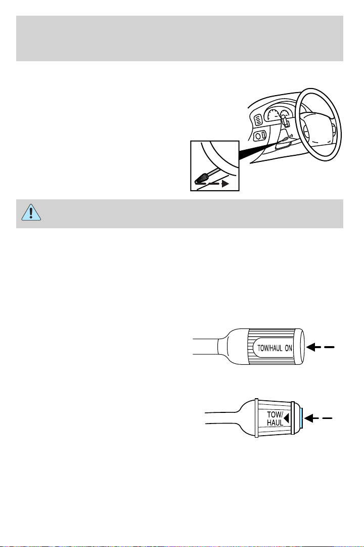
TILT STEERING WHEEL (IF EQUIPPED)
To adjust the steering wheel:
1. Pull and hold the steering wheel
release control toward you.
2. Move the steering wheel up or
down until you find the desired
location.
3. Release the steering wheel
release control. This will lock the
steering wheel in position.
Never adjust the steering wheel when the vehicle is moving.
TRANSMISSION CONTROL
Tow/Haul feature
(5–speed automatic transmission) (if equipped)
• Gearshift lever type A
• Gearshift lever type B
To activate, press the transmission
control switch (TCS) located on the
gearshift. The TOW/HAUL indicator
light will illuminate on the gearshift
lever or in the instrument cluster, depending on how your vehicle is
equipped. The transmission will operate in all gears. Press the
transmission control switch again to deactivate Tow/Haul mode. When
you shut off and re-start your vehicle, the transmission will automatically
return to normal mode with Tow/Haul feature deactivated, refer to the
Driving chapter for more information.
53
Page 54
Driver Controls
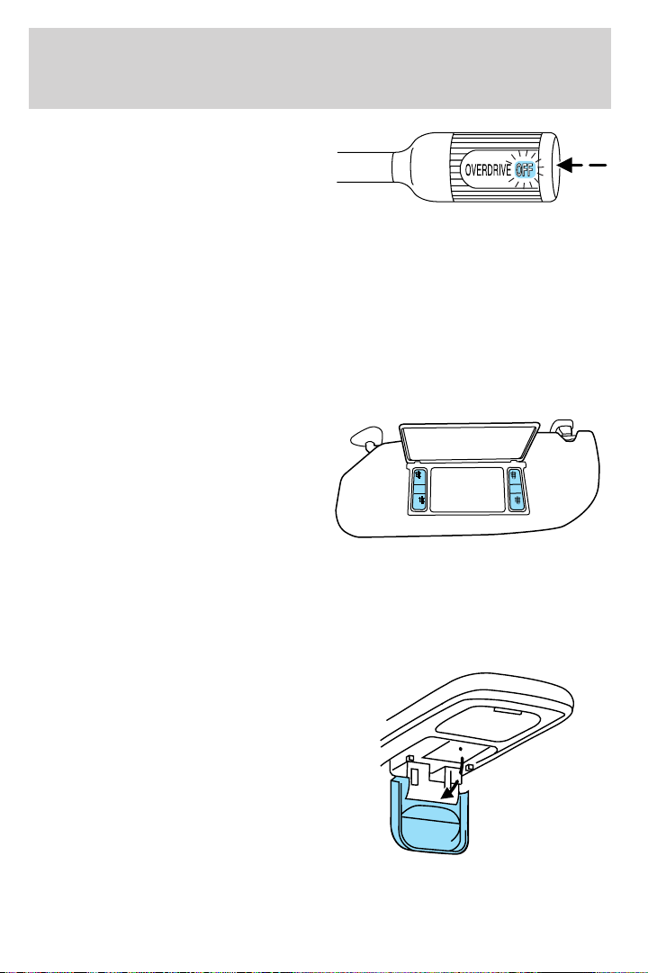
Overdrive cancel
(4–speed automatic
transmission) (if equipped)
To deactivate overdrive, press the
transmission control switch (TCS)
located on the gearshift. The OFF indicator light will illuminate on the
gearshift. The transmission will operate in all gears except overdrive.
Press the transmission control switch again to return to normal overdrive
mode. When you shut off and re-start your vehicle, the transmission will
automatically return to normal (Overdrive) mode.
For additional information about the gearshift and the transmission
control switch operation refer to the Driving chapter.
ILLUMINATED VISOR MIRROR (IF EQUIPPED)
Lift the mirror cover to turn on the
visor mirror lamps.
OVERHEAD CONSOLE (IF EQUIPPED)
The appearance of your vehicle’s overhead console will vary according to
your option package.
Storage compartment (if equipped)
Press the release on the door to
open the storage compartment.
The storage compartment may be
used to secure sunglasses or a
similar object.
54
Page 55
Driver Controls
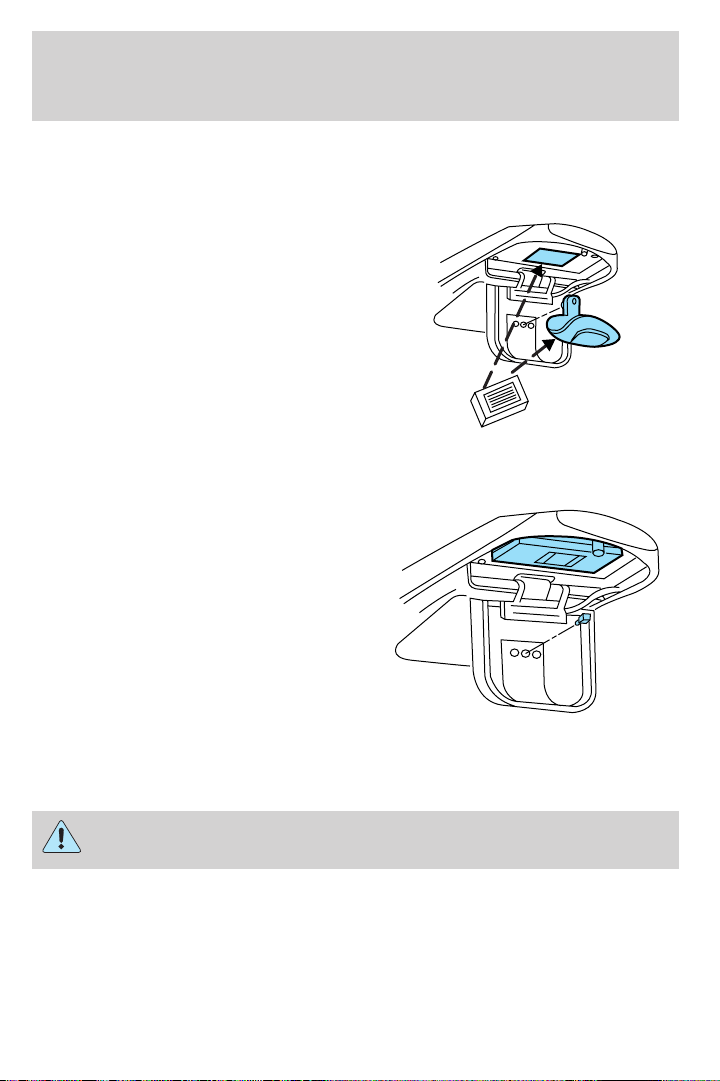
Install a garage door opener (if equipped)
The storage compartment can be used to hold a variety of aftermarket
garage door openers. To install your garage door opener:
1. Open the storage compartment
door.
2. Remove the storage clip and stow
it away.
3. Place the Velcro娂 strip onto the
back of the garage door opener
control.
4. Adhere the back of garage door
opener control to the Velcro娂 strip
found inside the storage
compartment. Make sure that the controls for the garage door opener
face outward.
5. Place the height adjusters onto
the back of the storage
compartment door. Add as many
adjusters needed to activate the
garage door opener.
6. Close the storage compartment
door and press the garage door
opener control to verify that it
works. If not, you may need to add
more adjusters.
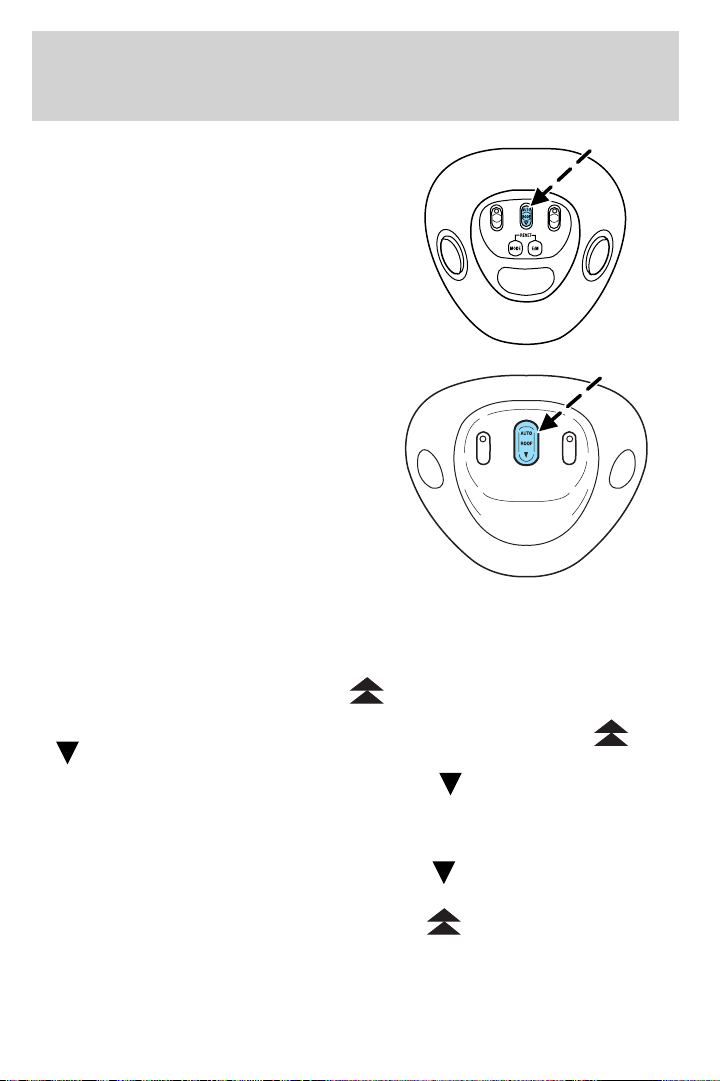
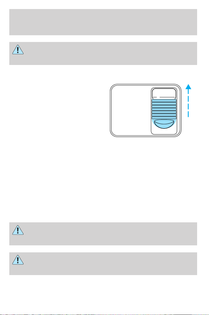
One-touch moon roof (if equipped)
The moon roof control is located on the overhead console.
Do not let children play with the moon roof or leave children
unattended in the vehicle. They may seriously hurt themselves.
55
Page 56
Driver Controls
With trip computer
Without trip computer
Note: The moon roof will open to the “comfort” position first before
opening all the way. The “comfort” position helps to alleviate rumbling
wind noise which may happen in the vehicle with the roof fully opened.
To open the moon roof: The moon roof is equipped with a one-touch
open feature. Press and release the
open to the “comfort” position. Press and release the control again to
fully open. To stop the one-touch open feature press either the
or control again.
To close the moon roof: Press and hold the
panel stops at the “comfort” position. Press and hold the control again
until the glass stops moving. When fully closed, the rear portion of the
glass panel will appear higher than the front portion.
To vent the moon roof: Press and hold the
roof must be in the closed position in order to move it into the
vent position. To close, press and hold the
panel stops moving.
The moon roof has a built-in sliding shade that can be manually opened
or closed when the glass panel is shut. To close the shade, pull it toward
the front of the vehicle.
control. The moon roof will
control until the glass
control. The moon
control until the glass
56
Page 57
Driver Controls
When closing the moon roof, you should verify that it is free of
obstructions and ensure that children and/or pets are not in the
proximity of the moon roof opening.
AUXILIARY POWER POINT
Power outlets are designed for
accessory plugs only. Do not
hang any type of accessory or
accessory bracket from the plug.
Improper use of the power
outlet can cause damage not
covered by your warranty.
The auxiliary power point is located
on the instrument panel.
Do not plug optional electrical accessories into the cigarette lighter. Use
the power point.
Do not use the power point for operating the cigarette lighter element.
The Maximum power each power point can supply depends on the fuse
rating. For example: a 20A fuse should supply a maximum of 240 Watts,
a 15A fuse should supply a maximum of 180 Watts and a 10A fuse should
supply a maximum of 120 Watts. Exceeding these limits will result in a
blown fuse.
Always keep the power point caps closed when not being used.
POWER POINT
POWER WINDOWS (IF EQUIPPED)
Do not leave children unattended in the vehicle and do not let
children play with the power windows. They may seriously injure
themselves.
When closing the power windows, you should verify they are free
of obstructions and ensure that children and/or pets are not in
the proximity of the window openings.
57
Page 58
Driver Controls
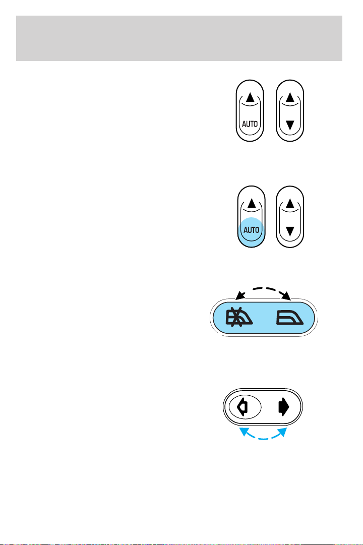
Press and hold the bottom part of
the rocker switch to open the
window. Press and hold the top part
of the rocker switch to close the
window.
One touch down
Allows the driver’s window to open
fully without holding the control
down. Press completely down on
AUTO and release quickly. Press
again to stop.
Window lock (if equipped)
The window lock feature allows only
the driver to operate the power
windows.
To lock out all the window controls
except for the driver’s press the left
side of the control. Press the right
side to restore the window controls.
Power rear slider window (if equipped)
• Press and hold the open arrow
side of control to open window.
• Press and hold the closed arrow
side of control to close window.
Accessory delay (if equipped)
With accessory delay, the window switches may be used for up to ten
minutes after the ignition switch is turned to the OFF position or until
any door is opened.
58
Page 59
POWER SIDE VIEW MIRRORS (IF EQUIPPED)
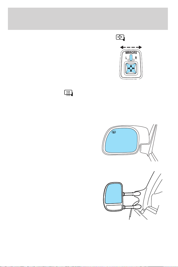
To adjust your mirrors:
1. Select L to adjust the left mirror
or R to adjust the right mirror.
2. Move the control in the direction
you wish to tilt the mirror.
3. Return to the center position to
disable the adjust function.
Driver Controls
Heated outside mirrors
The main mirror glass is heated automatically to remove ice, mist and
fog and activates when the vehicle is started.
Note: The mirrors may be hot to the touch but will not burn. This is a
normal condition.
Type A
The mirror heating elements are
designed to operate regardless of
the geographic location of the
vehicle. There is no switch to turn
on, or other operator involvement
required other than to start the
vehicle.
Type B
The spotter mirror, below the main
mirror, is not heated and must be
adjusted manually.
Do not remove ice from the mirrors with a scraper or attempt to
readjust the mirror glass if it is frozen in place. These actions
could cause damage to the glass and mirrors.
(if equipped)
59
Page 60
Driver Controls
Mirror mounted side turn signal indicator (if equipped)
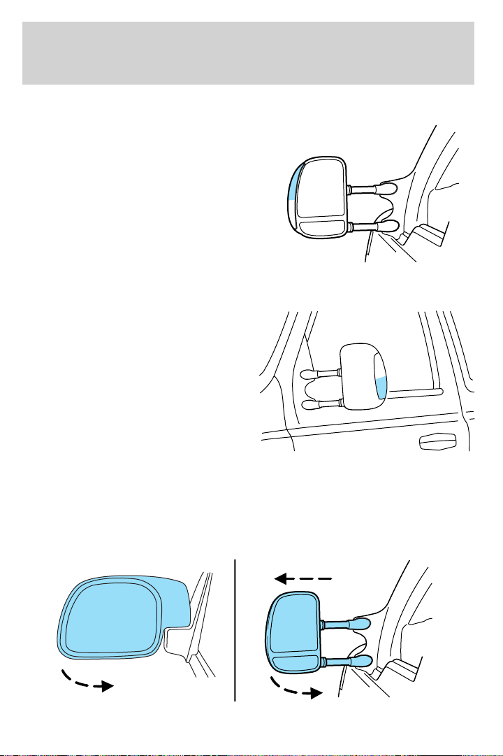
When the vehicle turn signals are
activated, the outer portion of the
mirror housing will blink amber.
The turn signal feature can be seen
by other drivers who may approach
from the rear of the vehicle.
Clearance lamps (if equipped)
Illuminates when the headlamps or
parking lamps are switched on.
This provides additional visibility of
your vehicle to other drivers on the
road.
Fold-away mirrors
The mirrors can be manually folded forward or backwards for narrow
spaces like driving through an automatic car wash or backing out of a
garage with the trailer tow mirror.
60
Page 61
Driver Controls
The telescoping feature (if equipped) allows the mirror to extend
approximately 3.15 inches (80 mm). This feature is especially useful to
the driver when towing a trailer.
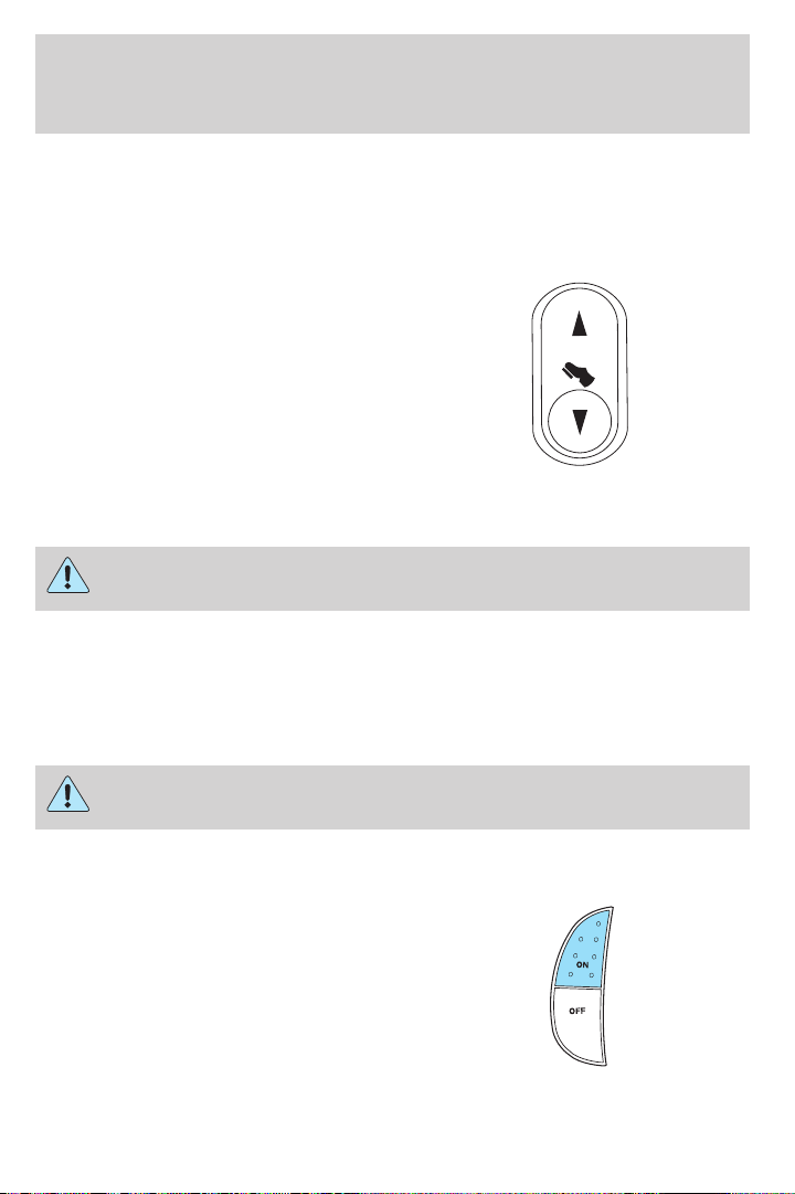
POWER ADJUSTABLE FOOT PEDALS (IF EQUIPPED)
The accelerator and brake pedal
should only be adjusted when the
vehicle is stopped and the gearshift
lever is in the P (Park) position.
Press and hold the rocker control to
adjust accelerator and brake pedal
toward you or away from you.
The adjustment allows for approximately 3 inches (71–76 mm) of
maximum travel.
Never adjust the accelerator and brake pedal with feet on the
pedals while the vehicle is moving.
SPEED CONTROL (IF EQUIPPED)
With speed control set, you can maintain a speed of 30 mph (48 km/h)
or more without keeping your foot on the accelerator pedal. Speed
control does not work at speeds below 30 mph (48 km/h).
Do not use the speed control in heavy traffic or on roads that
are winding, slippery or unpaved.
Setting speed control
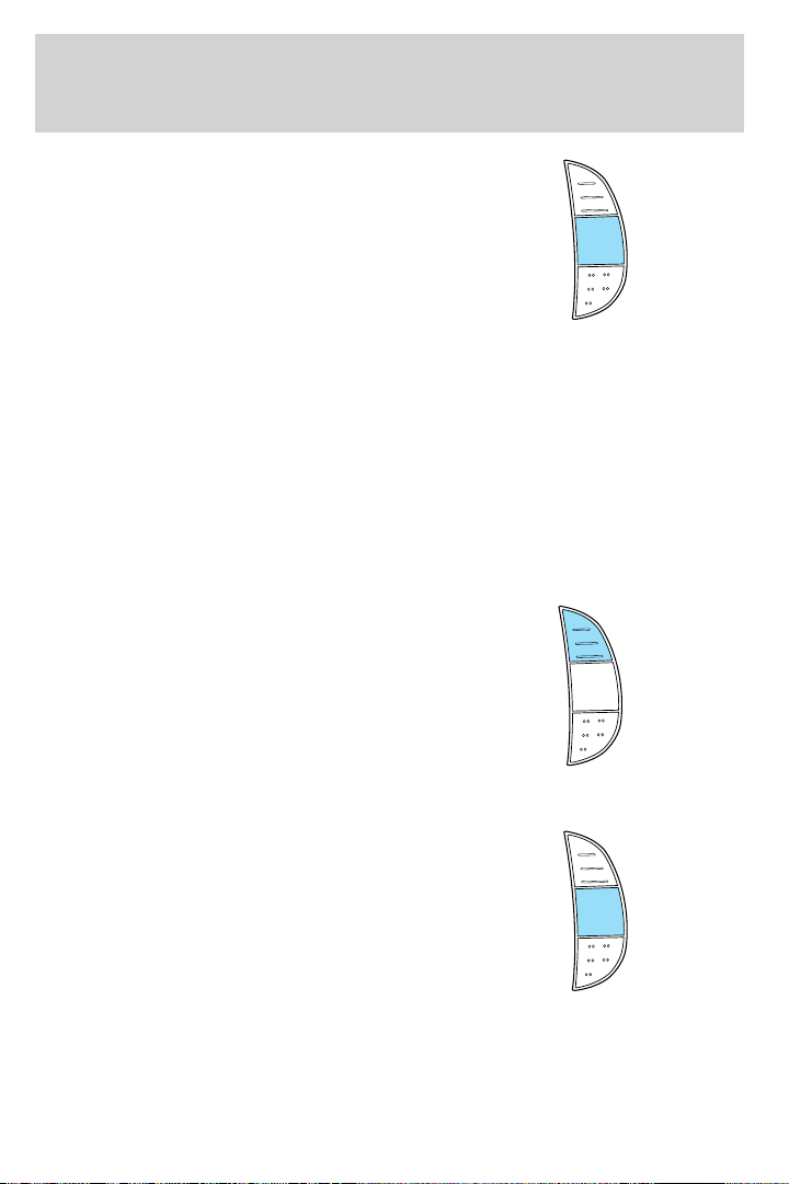
The controls for using your speed
control are located on the steering
wheel for your convenience.
1. Press the ON control and release
it.
2. Accelerate to the desired speed.
61
Page 62
Driver Controls
3. Press the SET ACCEL control
and release it.
4. Take your foot off the accelerator
pedal.
5. The indicator light on the
instrument cluster will turn on.
Note:
• Vehicle speed may vary momentarily when driving up and down a
steep hill.
• If the vehicle speed increases above the set speed on a downhill, you
may want to apply the brakes to reduce the speed.
• If the vehicle speed decreases more than 10 mph (16 km/h) below
your set speed on an uphill, your speed control will disengage.
Resuming a set speed
Press the RES (resume) control and
release it. This will automatically
return the vehicle to the previously
set speed. The RES control will not
work if the vehicle speed is not
faster than 30 mph (48 km/h).
RES
ACCEL
COAST
RES
SET
ACCEL
COAST
SET
Increasing speed while using speed control
There are two ways to set a higher
speed:
• Press and hold the SET ACCEL
control until you get to the
desired speed, then release the
control. You can also use the SET
RES
SET
ACCEL
COAST
ACCEL control to operate the
Tap-Up function. Press and
release this control to increase the vehicle set speed in increments by
1 mph (1.6 km/h).
• Use the accelerator pedal to get to the desired speed. When the
vehicle reaches that speed press and release the SET ACCEL control.
62
Page 63
Driver Controls
Reducing speed while using speed control
There are two ways to reduce a set
speed:
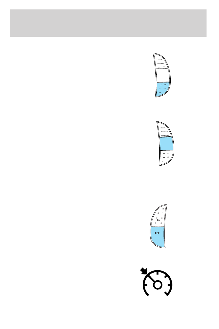
• Press and hold the COAST
control until you get to the
desired speed, then release the
control. You can also use the
COAST control to operate the
Tap-Down function. Press and
release this control to decrease the vehicle set speed in increments by
1 mph (1.6 km/h).
• Depress the brake pedal until the
desired vehicle speed is reached,
press the SET ACCEL control.
Turning off speed control
There are two ways to turn off the speed control:
• Depress the brake pedal or the clutch pedal (if equipped). This will
not erase your vehicle’s previously set speed.
• Press the speed control OFF
control.
Note: When you turn off the speed
control or the ignition, your speed
control set speed memory is erased.
RES
SET
ACCEL
COAST
RES
SET
ACCEL
COAST
Indicator light (if equipped)
This light comes on when either the
SET ACCEL or RES controls are
pressed. The vehicle speed must be
at or above 48 km/h (30 mph). It
turns off when the speed control
OFF control is pressed, the brake or
clutch is applied, or the ignition is turned to the OFF position.
63
Page 64
Driver Controls
HOMELINK姞 WIRELESS CONTROL SYSTEM WITH TRAVELNOTE姞
(IF EQUIPPED)
The HomeLink威 Wireless Control System, located on the driver’s visor,
provides a convenient way to replace up to three hand-held transmitters
with a single built-in device. This feature will learn the radio frequency
codes of most transmitters to operate garage doors, entry gate operators,
security systems, entry door locks, and home or office lighting.
When programming your HomeLink威 Wireless Control System to
a garage door or gate, be sure that people and objects are out of
the way to prevent potential harm or damage.
Do not use the HomeLink威 Wireless Control System with any garage
door opener that lacks safety stop and reverse features as required by
U.S. federal safety standards (this includes any garage door opener
model manufactured before April 1, 1982). A garage door which cannot
detect an object, signaling the door to stop and reverse, does not meet
current U.S. federal safety standards. For more information, contact
HomeLink威 at: www.homelink.com or 1–800–355–3515.
Retain the original transmitter for use in other vehicles as well as for
future programming procedures (i.e. new HomeLink威 equipped vehicle
purchase). It is also suggested that upon the sale of the vehicle, the
programmed Homelink威 buttons be erased for security purposes, refer to
Programming in this section.
Programming
Do not program HomeLink威 with the vehicle parked in the garage.
Note: Your vehicle may require the ignition switch to be turned to the
ACC position for programming and/or operation of the HomeLink威.Itis
also recommended that a new battery be placed in the hand-held
transmitter of the device being programmed to HomeLink威 for quicker
training and accurate transmission of the radio-frequency signal.
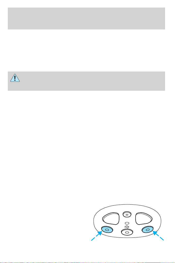
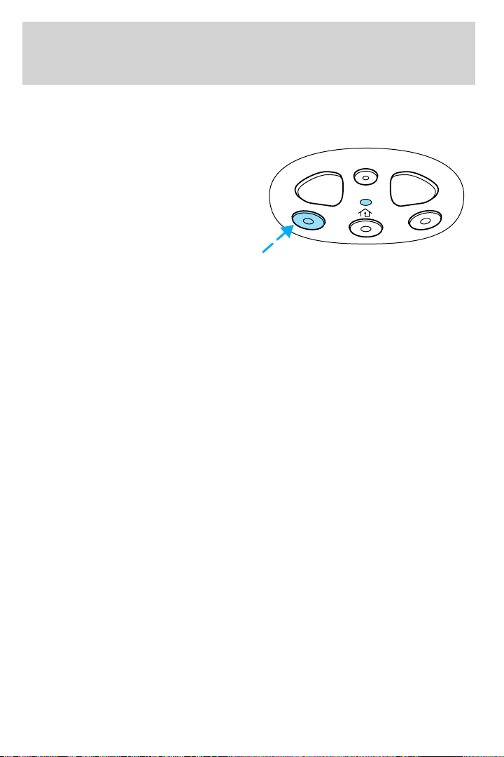
1. Press and hold the two outside
buttons releasing only when the red
light begins to flash after 20
seconds. Do not repeat step one to
program additional hand-held
transmitters to the remaining two
HomeLink威 buttons. This will erase
previously programmed hand-held
transmitter signals into HomeLink威.
REC DEL PLAY
64
Page 65
Driver Controls
2. Position the end of your hand-held transmitter 1–3 inches (2–8 cm)
away from the HomeLink威 button you wish to program (located on your
visor) while keeping the red light in view.
3. Simultaneously press and hold
both the HomeLink威 and hand-held
transmitter button. Do not release
the buttons until step 4 has been
completed.
Some entry gates and garage door
openers may require you to replace
step 3 with procedures noted in the
“Gate Operator and Canadian Programming” in this section for Canadian
residents.
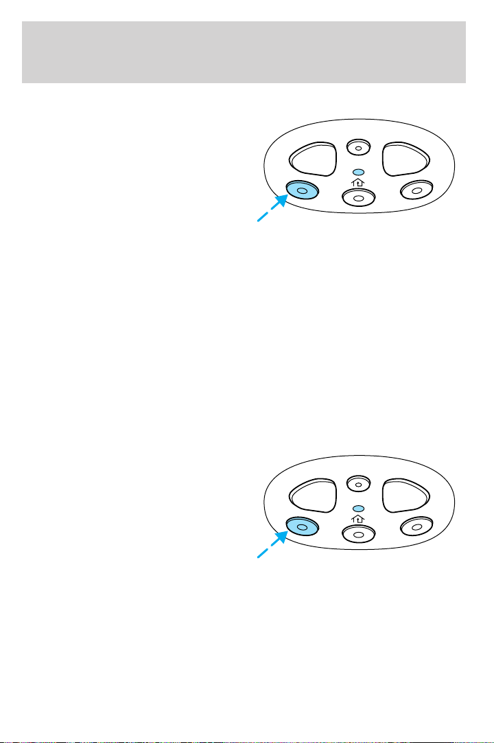
4. The red light will flash slowly and then rapidly. Release both buttons
when the red light flashes rapidly. (The rapid flashing light indicates
acceptance of the hand-held transmitters’ radio frequency signals.)
5. Press and hold the just-trained HomeLink威 button and observe the red
light. If the light is a constant red, programming is complete and your
device should activate when the HomeLink威 button is pressed and
released. Note: To program the remaining two HomeLink威 buttons,
begin with step 2 in the “Programming” section — do not repeat step 1.
Note: If the red light blinks rapidly for two seconds and then turns to a
continuous red, proceed with steps 6 through 8 to complete
programming of a rolling code equipped device.
6. At the garage door opener receiver (motor-head unit) in the garage,
locate the “learn” or “smart” button (usually near where the hanging
antenna wire is attached to the unit).
7. Press and release the “learn” or “smart” button. (The name and color
of the button may vary by manufacturer.)
Note: There are 30 seconds in which to initiate step eight.
8. Return to the vehicle and firmly press, hold for two seconds and
release the HomeLink威 button. Repeat the press/hold/release sequence
again, and, depending on the brand of the garage door opener (or other
rolling code equipped device), repeat this sequence a third time to
complete the programming.
HomeLink威 should now activate your rolling code equipped device. To
program additional HomeLink威 buttons begin with step 2 in the
“Programming” section. For questions or comments, please contact
HomeLink at www.homelink.com or 1–800–355–3515.
REC DEL PLAY
65
Page 66
Driver Controls
Gate Operator & Canadian Programming
During programming, your
hand-held transmitter may
automatically stop transmitting —
not allowing enough time for
HomeLink威 to accept the signal
from the hand-held transmitter.
After completing steps 1 and 2
outlined in the “Programming”
section, replace step 3 with the following:
Note: If programming a garage door opener or gate operator, it is
advised to unplug the device during the “cycling” process to prevent
overheating.
• Continue to press and hold the HomeLink威 button (note step 3 in the
“Programming” section) while you press and release — every two
seconds (“cycle”) your hand-held transmitter until the frequency
signal has been accepted by the HomeLink威. The indicator light will
flash slowly and then rapidly after HomeLink威 accepts the radio
frequency signal.
• Proceed with step 4 in the “Programming” section.
Operating the HomeLink姞 Wireless Control System
To operate, simply press and release
the appropriate HomeLink威 button.
Activation will now occur for the
trained product (garage door, gate
operator, security system, entry
door lock, or home or office lighting
etc.). For convenience, the
hand-held transmitter of the device
may also be used at any time. In the event that there are still
programming difficulties, contact HomeLink威 at www.homelink.com or
1–800–355–3515.
REC DEL PLAY
REC DEL PLAY
66
Page 67
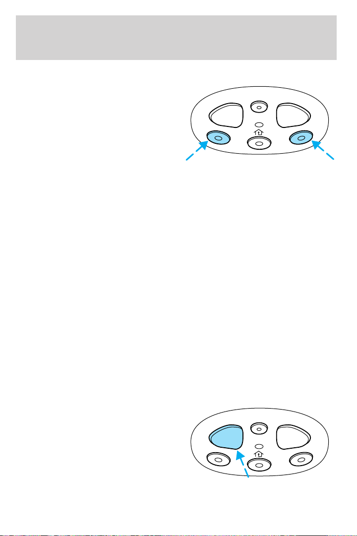
Driver Controls
Erasing HomeLink姞 buttons
To erase the three programmed
buttons (individual buttons cannot
be erased):
• Press and hold the two outer
HomeLink威 buttons until the
indicator light begins to
flash-after 20 seconds. Release
both buttons. Do not hold for
longer that 30 seconds.
HomeLink威 is now in the train (or learning) mode and can be
programmed at any time beginning with step 2 in the “Programming”
section.
Reprogramming a single HomeLink姞 button
To program a device to HomeLink威 using a HomeLink威 button previously
trained, follow these steps:
1. Press and hold the desired HomeLink威 button. Do NOT release the
button.
2. The indicator light will begin to flash after 20 seconds. Without
releasing the HomeLink威 button, follow step 2 in the “Programming”
section.
For questions or comments, contact HomeLink威 at www.homelink.com
or 1–800–355–3515.
REC DEL PLAY
Operating TravelNote姞
TravelNote威 records and stores messages for up to three minutes in total
length with simple controls. When you get an idea or remember
something important while you’re driving, you don’t have to try to
scribble it down or pull off the side of the road. All you have to do is
push a button and begin speaking.
To record a message:
1. Press and release the REC
button one time to start recording.
REC DEL PLAY
(An audible tone will sound,
confirming the onset of recording).
2. Press and release the REC
button a second time to end
recording. (An audible tone will sound again, confirming the end of
recording and the red indicator light will turn off.)
67
Page 68
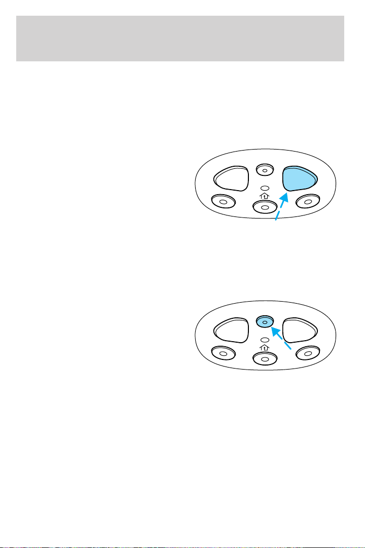
Driver Controls
3. While a message is being recorded, the indicator light will be a solid
red.
4. If the message exceeds the available memory space, two tones will
sound, the indicator light will flash amber and recording will end.
The indicator light will flash amber and an “error” tone will sound if the
REC button is pressed when memory is full.
To play a message:
1. Press and release the PLAY
button to play the message.
2. Press and hold the PLAY button
to hear all the messages in
consecutive order starting with the
most recent.
3. If the PLAY button is pressed while a message is being listened to,
TravelNote威 will skip to the beginning of the next message.
4. During all PLAY functions, the indicator light will be a solid green.
The indicator light will flash amber and an “error” tone will sound if the
PLAY button is pressed but no message is currently in memory.
To delete a message:
1. Press and release the DEL button
while listening to a message or
shortly after. The indicator light will
flash green twice.
2. To delete all recorded messages,
simultaneously press and release the
PLAY and REC buttons at the same time. The indicator light will flash
green twice.
If the DEL button is inadvertently pressed or the time allotted (five
seconds) has passed, the indicator light will flash amber and an “error”
tone will sound.
REC DEL PLAY
REC DEL PLAY
68
Page 69
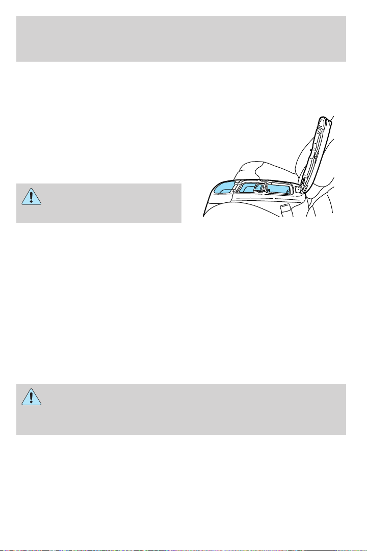
Driver Controls
CENTER CONSOLE (IF EQUIPPED)
Your vehicle may be equipped with a variety of console features. These
include:
• Utility compartment with
cassette/CD holder
• Coin holder
• Pen holder
• Writing surface
Use only soft cups in the
cupholder. Hard objects can
injure you in a collision.
CELL PHONE USE
The use of Mobile Communications Equipment has become increasingly
important in the conduct of business and personal affairs. However,
drivers must not compromise their own or others’ safety when using
such equipment. Mobile Communications can enhance personal safety
and security when appropriately used, particularly in emergency
situations. Safety must be paramount when using mobile communications
equipment to avoid negating these benefits.
Mobile Communication Equipment includes, but is not limited to cellular
phones, pagers, portable email devices, in vehicle communications
systems, telematics devices and portable two-way radios.
A driver’s first responsibility is the safe operation of the vehicle.
The most important thing you can do to prevent a crash is to
avoid distractions and pay attention to the road. Wait until it is safe to
operate Mobile Communications Equipment.
69
Page 70
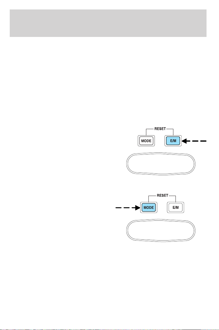
Driver Controls
TRIP COMPUTER (IF EQUIPPED)
The trip computer tells you about the condition of your vehicle through
a constant monitor of vehicle systems. You may select display features on
the trip computer for a display of status.
The appearance of your vehicle’s trip computer may differ depending on
your vehicle’s option package, but the functions are the same.
The trip computer only operates with the ignition in the ON position.
Trip computer features are as follows:
Selectable features
English/metric display
Press this control to change the trip
computer display between English
and metric units.
Mode control
Each press of the MODE control will
display a different feature as follows:
Average fuel economy. The
display will indicate the vehicle’s
average fuel economy in miles/gallon
(or liters/100 km) since the average
fuel economy was last reset.
If you calculate your average fuel
economy by dividing gallons of fuel used by miles traveled (liters used by
kilometers traveled), your figure may be different than displayed for the
following reasons:
• your vehicle was not perfectly level during fill-up
• differences in the automatic shut-off points on the fuel pumps at
service stations
• variations in top-off procedure from one fill-up to another
• rounding of the displayed values to the nearest liter (gallon)
70
Page 71
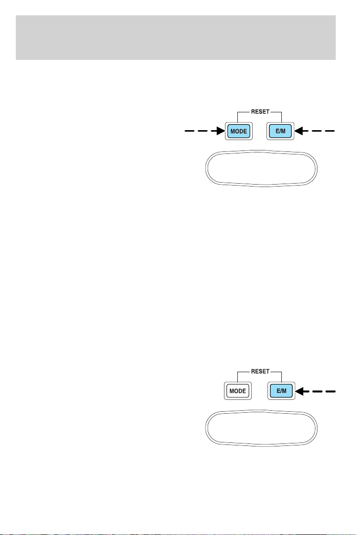
Driver Controls
To reset the average fuel economy:
1. Press the MODE control repeatedly until average fuel economy is
displayed (this is the only resettable display).
2. Press the E/M and MODE
controls simultaneously. The display
will illuminate the “AVG” indicator.
While the indicator is lit, release
both controls to reset the average
fuel economy.
Fuel range. This function estimates approximately how far you can
drive with the fuel remaining in your tank under normal driving
conditions. Remember to turn the ignition OFF when refueling to allow
this feature to correctly detect the added fuel.
The DTE function will flash for 5 seconds when you have approximately:
• 50 miles (80 km) left before you run out of fuel
• 25 miles (40 km )
• 10 miles (16 km)
DTE is calculated using a running average fuel economy, which is based
on your recent driving history of 500 miles (800 km). This value is not
the same as the average fuel economy display. The running average fuel
economy is reinitialized to a factory default value if the battery is
disconnected.
Outside air temperature
The temperature can be displayed in
Centigrade or Fahrenheit by
pressing the E/M control.
If the outside temperature falls
below 38°F(3°C), the display will
alternate from “ICE” to the outside
temperature at a two second rate
for one minute.
Off. In this mode the display is off.
Compass
The compass display is contained in the overhead console. The vehicle
heading is displayed as one of N, NE, E, SE, S, SW, W and NW.
71
Page 72
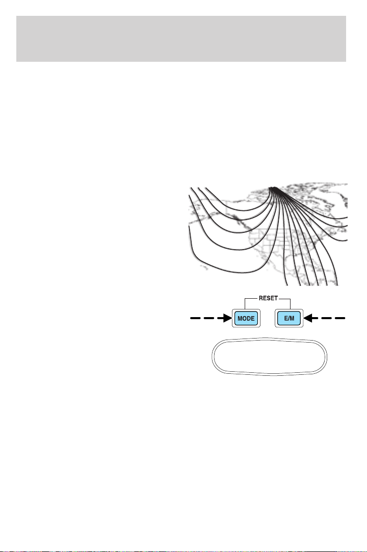
Driver Controls
The compass heading is displayed in average fuel economy modes, fuel
range modes and temperature modes.
The compass reading may be affected when you drive near large
buildings, bridges, power lines and powerful broadcast antennas.
Magnetic or metallic objects placed in or on the vehicle may also affect
compass accuracy. Adjustments may need to be made to the zone and
calibration of the compass.
Compass zone adjustment
1. Determine which magnetic zone
you are in for your geographic
location by referring to the zone
map.
2. Locate the trip computer on the
4
overhead console.
3. Turn ignition to the ON position.
5
4. Press and hold both trip
computer controls. After
approximately four seconds, the trip
computer will enter zone setting
mode. Zone setting mode is
indicated when the display lights the
“ZONE” indicator.
5. Release both controls.
Subsequent pressing of either control will increment the zone. Press the
control repeatedly until the correct zone setting for your geographic
location is displayed on the trip computer.
6. To exit the zone setting mode and save the displayed zone in memory,
release both controls for greater than five seconds.
Compass calibration adjustment
Perform this adjustment in an open area free from steel structures and
high voltage lines.
For optimum calibration, turn off all electrical accessories (heater/air
conditioning, wipers, etc.) and make sure all vehicle doors are shut.
1. Locate the trip computer located in the overhead console.
123
6 7 8 9 1011
15
14
13
12
72
Page 73
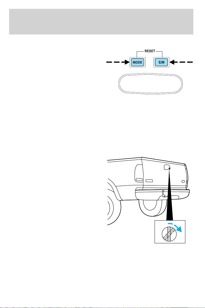
Driver Controls
2. Start the vehicle.
3. Press and hold both trip
computer controls. After
approximately eight seconds, the
trip computer will enter CAL mode.
CAL mode is indicated when the
display lights the “CAL” indicator.
4. Release both controls. The display
will return to normal, except that
the CAL indicator will remain lit until the compass is successfully
calibrated.
5. Slowly drive the vehicle in a circle (less than 5 km/h [3 mph]) until
the CAL indicator turns off. It may take up to five circles to complete
calibration.
6. The compass is now calibrated.
TAILGATE LOCK (IF EQUIPPED)
Your vehicle may be equipped with a
tailgate lock designed to prevent
theft of the tailgate.
• Insert ignition key and turn to the
right to engage lock.
• Turn ignition key to the left to
unlock.
73
Page 74
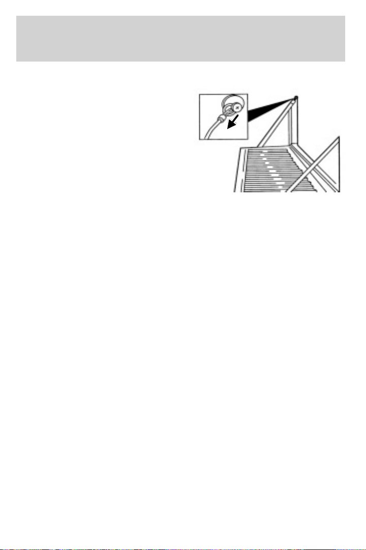
Driver Controls
Tailgate removal
Your tailgate is removable to allow
more room for loading.
1. Lower the tailgate.
2. Use a screwdriver to pry the
spring clip (on each connector) past
the head of the support screw.
Disconnect cable.
3. Disconnect the other cable.
4. Lift tailgate to a 45 degree angle.
5. Lift right side off of its hinge.
6. Lift left side off of its hinge.
To install, follow the removal procedures in reverse order.
74
Page 75
Locks and Security
KEYS
The key operates all locks on your vehicle. You should always carry a
second key with you in a safe place in case you require it in an
emergency.
Your keys are programmed to your vehicle; using a non-programmed key
will not permit your vehicle to start. If you lose your dealer supplied
keys, replacement keys are available through your authorized dealer.
POWER DOOR LOCKS (IF EQUIPPED)
Press control to unlock all doors.
Press control to lock all doors.
Smart locks (if equipped)
This feature prevents you from locking yourself out of the vehicle if your
key is still in the ignition.
When you open the driver’s door and you lock the vehicle with the
power door lock control, all the doors will lock, then the driver’s door
will automatically unlock reminding you that your key is still in the
ignition.
The vehicle can still be locked, with the key in the ignition, using the
manual lock button on the door, locking the driver’s door with a key, by
simultaneously pressing button 7 • 8 and the 9 • 0 controls on the
remote entry keypad (if equipped), or using the lock button on the
remote entry transmitter (if equipped).
75
Page 76
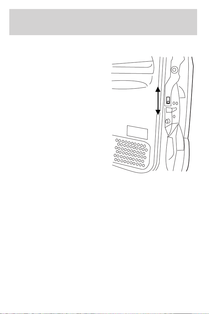
Locks and Security
Childproof door locks
• When these locks are set, the
rear doors cannot be opened from
the inside.
• The rear doors can be opened
from the outside when the doors
are unlocked.
The childproof locks are located on
rear edge of each rear door and
must be set separately for each
door. Setting the lock for one door
will not automatically set the lock
for both doors.
• Move lock control up to engage
the childproof lock.
• Move control down to disengage
childproof locks.
REMOTE ENTRY SYSTEM (IF EQUIPPED)
This device complies with part 15 of the FCC rules and with RS-210 of
Industry Canada. Operation is subject to the following two conditions:
(1) This device may not cause harmful interference, and (2) This device
must accept any interference received, including interference that may
cause undesired operation.
Changes or modifications not expressly approved by the party
responsible for compliance could void the user’s authority to
operate the equipment.
The typical operating range for your remote entry transmitter is
approximately 33 feet (10 meters). A decrease in operating range could
be caused by:
• weather conditions,
• nearby radio towers,
• structures around the vehicle, or
• other vehicles parked next to your vehicle.
76
Page 77
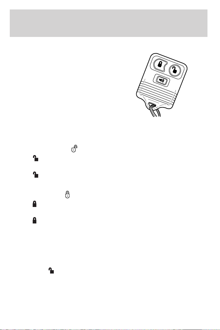
Locks and Security
Your vehicle is equipped with a remote entry system which allows you to:
• unlock the vehicle doors without
a key.
• lock all the vehicle doors without
a key.
• activate the personal alarm.
If there is any potential remote keyless entry problem with your vehicle,
ensure ALL remote entry transmitters are taken to the dealership, to
aid in troubleshooting.
Unlocking the doors
1. Press and release to unlock the driver’s door. Note: The interior
lamps will illuminate.
2. Press
doors.
Locking the doors
1. Press and release to lock all the doors. The parking lamps will flash
if all the doors are closed and locked.
2. Press
doors are closed and locked. Note: The doors will lock again, the horn
will chirp once, and the parking lamps will flash once more.
If any of the doors are not properly closed the horn will make two quick
chirps.
and release again within three seconds to unlock all the
and release again within three seconds to confirm that all the
Power door lock disable feature (if equipped)
The UNLOCK
inside the vehicle when:
• the ignition has been turned to the 3 (OFF) position, and
• 20 seconds elapse after all vehicle doors are closed and locked using
the remote entry transmitter, or the power door lock control (while
the accompanying door is open).
feature on your power door locks will not work from
77
Page 78
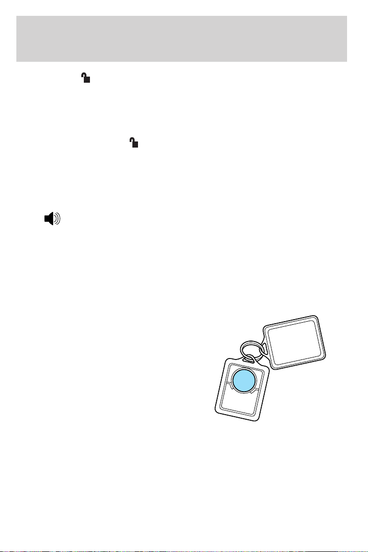
Locks and Security
The UNLOCK feature will work again after:
• a door has become ajar,
• the ignition is turned to the 4 (ON) position,
• unlocking the vehicle using the keyless entry keypad,
• or using the UNLOCK
equipped).
This feature is initially deactivated, but may be activated by taking your
vehicle to an authorized Ford dealer.
Sounding a panic alarm
Press
(ACCESSORY) or 4 (ON) to deactivate.
Note: The panic alarm will only operate when the ignition is in the 3
(OFF) position.
Replacing the battery
The remote entry transmitter uses one coin type three-volt lithium
battery CR2032 or equivalent.
To replace the battery:
1. Twist a thin coin between the two
halves of the remote entry
transmitter near the key ring. DO
NOT TAKE THE RUBBER COVER
AND CIRCUIT BOARD OFF THE
FRONT HOUSING OF THE
REMOTE ENTRY TRANSMITTER.
to activate the alarm. Press again or turn the ignition to 1
control on your remote entry transmitter (if
78
Page 79
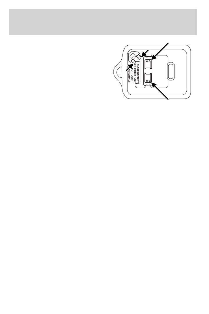
Locks and Security
2. Do not wipe off any grease on the
battery terminals on the back
surface of the circuit board.
3. Remove the old battery. Note: Please refer to local regulations when
disposing of transmitter batteries.
4. Insert the new battery. Refer to the diagram inside the remote entry
transmitter for the correct orientation of the battery. Press the battery
down to ensure that the battery is fully seated in the battery housing
cavity.
5. Snap the two halves back together.
Note: Replacement of the battery will not cause the remote transmitter
to become deprogrammed from your vehicle. The remote transmitter
should operate normally after battery replacement.
Replacing lost remote entry transmitters
If you would like to have your remote entry transmitter reprogrammed
because you lost one, or would like to buy additional remote entry
transmitters, you can either reprogram them yourself, or take all
remote entry transmitters to your authorized dealer for
reprogramming.
How to reprogram your remote entry transmitters
You must have all remote keyless entry keypads and remote entry
transmitters (maximum of four) available before beginning this
procedure.
79
Page 80
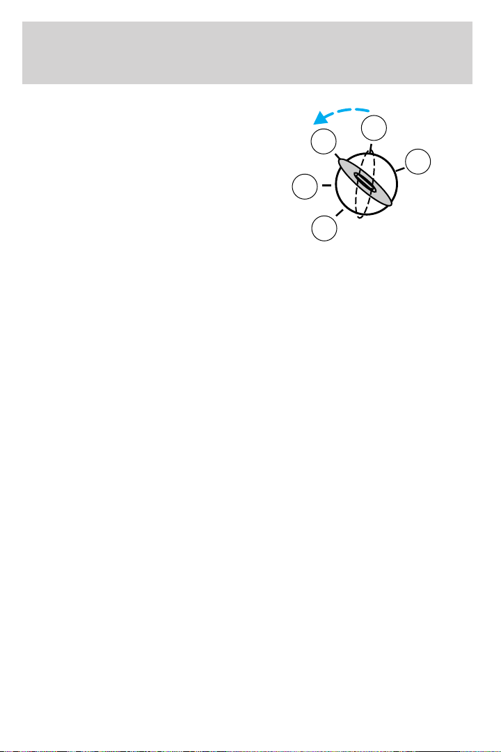
Locks and Security
To program the keyless entry
keypads remote entry transmitters
yourself:
1. Ensure the vehicle is
electronically unlocked.
2. Put the key in the ignition.
3. Turn the key from the 2 (LOCK)
position to 3 (OFF).
4. Cycle eight times rapidly (within
10 seconds) between the 3 (OFF)
position and 4 (ON). Note: The eighth turn must end in the 4 (ON)
position.
5. The doors will lock, then unlock, to confirm that the programming
mode has been activated.
6. Within 20 seconds, program the keyless entry keypad by pressing the
7 • 8 and the 9 • 0 controls at the same time.
7. The doors will lock, then unlock, to confirm that the keypad
programming mode has been activated.
8. Within 20 seconds, program the remote entry transmitter by pressing
any button on the transmitter. Note: If more than 20 seconds have
passed you will need to start the procedure over again.
9. The doors will again lock, then unlock, to confirm that this remote
entry transmitter has been programmed.
10. Repeat Step 8 to program each additional remote keypad or entry
transmitter.
11. Turn the ignition to the 3 (OFF) position after you have finished
programming all of the remote entry transmitters. Note: If more than 20
seconds have passed you will need to start the procedure over again.
12. The doors will once again lock, then unlock, to confirm that the
programming mode has been exited.
3
2
1
4
5
Illuminated entry
The interior lamps illuminate when the remote entry system is used to
unlock the door(s).
The illuminated entry system will turn off the interior lights if:
• the ignition switch is turned to the 4 (ON) position, or
• the remote transmitter lock control is pressed, or
80
Page 81

Locks and Security
• the 7 • 8 and the 9 • 0 controls on the keyless entry keypad are
pressed, or
• after 25 seconds of illumination.
The dome lamp control (if equipped) must not be set to the off position
for the illuminated entry system to operate.
The inside lights will not turn off if:
• they have been turned on with the dimmer control, or
• any door is open.
The battery saver will shut off the interior lamps 30 minutes after the
ignition has been turned to the 3 (OFF) position, 10 minutes after if the
dome lamp is off, and 30 minutes after if the dome lamp switch is left on.
Autolock (if equipped)
This feature automatically locks all vehicle doors when the following
conditions are met:
• the ignition is in the 4 (ON) position,
• all doors are closed,
• the brake is pressed before reaching 8 km/h (5 mph) and
• the vehicle is traveling more than 8 km/h (5 mph).
Relock
The autolock feature repeats when the following conditions are met:
• the vehicle’s speed is less than 8 km/h (5 mph), and
• any door is opened then closed while the ignition is in the 4 (ON)
position, and
• the brake is pressed before reaching 8 km/h (5 mph), and
• the vehicle is traveling more than 8 km/h (5 mph).
Deactivating/activating the autolock feature
Before following the procedure, make sure that the ignition is in the 3
(OFF) position and all vehicle doors are closed.
You must complete Steps 1-7 within 30 seconds or the procedure will
have to be repeated. If the procedure needs to be repeated, you must
wait 30 seconds.
1. Turn the ignition key to the 4 (ON) position.
2. Press the power door unlock control three times.
81
Page 82
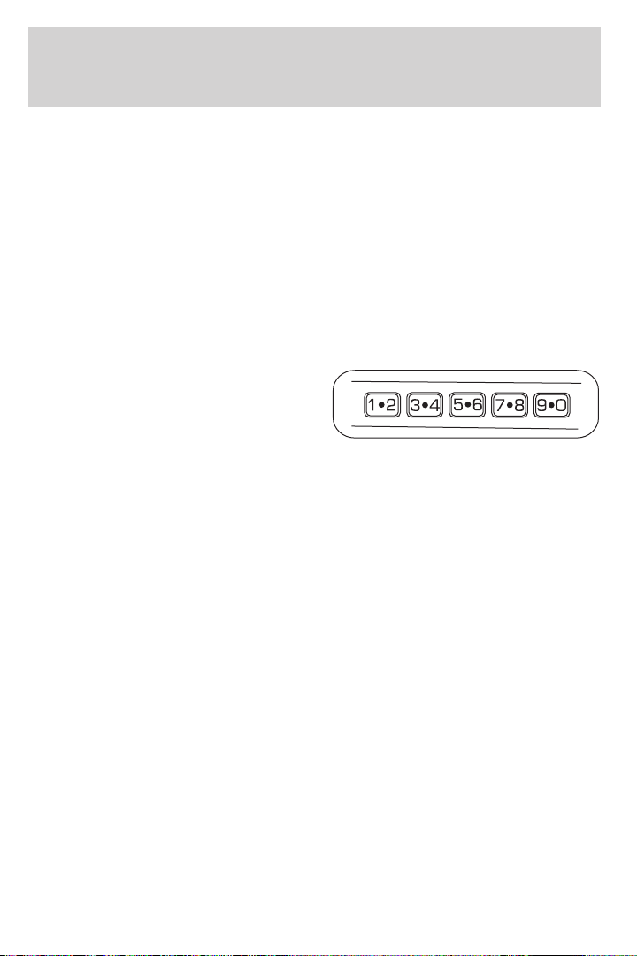
Locks and Security
3. Turn the ignition key from the 4 (ON) to the 3 (OFF) position.
4. Press the power door unlock control three times.
5. Turn the ignition back to the 4 (ON) position. The horn will chirp.
6. Press the unlock control, then press the lock control. The horn will
chirp once if autolock was deactivated or twice (one short and one long
chirp) if autolock was activated. Note: Pressing the power door
lock/unlock control again will toggle between activating and deactivating
the autolock feature.
7. Turn the ignition to the 3 (OFF) position. The horn will chirp once to
confirm the procedure is complete.
KEYLESS ENTRY SYSTEM
You can use the keyless entry
keypad to lock or unlock the doors
without using a key.
The keypad can be operated with
the factory set 5–digit entry code;
this code is located on the owner’s wallet card in the glove box, is
marked on the computer module, and is available from your authorized
dealer. You can also create your own 5–digit personal entry code.
When pressing the controls on the keypad, press the middle of the
controls to ensure a good activation.
Programming a personal entry code
To create your own personal entry code:
1. Enter the factory set code.
2. Within five seconds press the 1 • 2 on the keypad.
3. Enter your personal 5-digit code. Each number must be entered
within five seconds of each other.
4. The doors will again lock then unlock to confirm that your personal
keycode has been programmed to the module.
Tips:
• Do not set a code that uses five of the same number.
• Do not use five numbers in sequential order.
• The factory set code will work even if you have set your own personal
code.
• If you set a second personal code it will erase your first personal code.
82
Page 83

Locks and Security
Erasing personal code
1. Enter the factory set 5–digit code.
2. Within five seconds, press the 1 • 2 on the keypad and release.
3. Press and hold the 1 • 2 for two seconds. This must be done within
five seconds of completing Step 2.
Your personal code is now erased and only the factory set 5–digit code
will work.
Anti-scan feature
If an incorrect code has been entered 7 times (35 consecutive button
presses), the keypad will go into an anti-scan mode. This mode disables
the keypad for one minute and the keypad lamp will flash during this
time.
The anti-scan feature will turn off after:
• one minute of keypad inactivity.
• pressing the
• the ignition is turned to the 4 (ON) position.
Unlocking and locking the doors using keyless entry
To unlock the driver’s door, enter the factory set 5-digit code or your
personal code. Each number must be pressed within five seconds of each
other. The interior lamps will illuminate after entering a valid keypad
entry code.
To unlock all doors, press the 3 • 4 control within five seconds.
To lock all doors, press the 7 • 8 and the 9 • 0 at the same time. You
do not need to enter the keypad code first. Note: The interior lamps
will turn off.
Autolock (if equipped)
This feature automatically locks all vehicle doors when the following
conditions are met:
• the ignition key is in the 4 (ON) position,
• all the doors are closed,
• the brake is pressed before reaching 5 mph (8 km/h), and
• the vehicle is traveling more than 5 mph (8 km/h).
Relock
The autolock feature repeats when the following conditions are met:
• the vehicle’s speed is less than 5 mph (8 km/h),
control on the remote entry transmitter.
83
Page 84

Locks and Security
• any door is opened then closed while the ignition is in the 4 (ON)
position,
• the brake is pressed before reaching 5 mph (8 km/h), and
• the vehicle is traveling more than 5 mph (8 km/h).
To deactivate/reactivate the autolock feature using the keypad
Your vehicle comes with the autolock feature activated. To
deactivate/reactivate this feature:
1. Ensure that the anti-theft system is not armed.
2. Turn the ignition to the 3 (OFF) position.
3. Close all the doors, liftgate and cargo doors.
4. Enter the 5-digit entry code.
5. Press and hold the 7 • 8. While holding the 7 • 8, press and release
the 3 • 4.
6. Release the 7 • 8.
The horn will chirp once when the system has been successfully
deactivated.
The horn will chirp twice (one short and one long chirp) when the
system has been successfully reactivated.
To deactivate/reactivate the autolock feature using the power door
unlock control
You must complete Steps 1-7 within 30 seconds or the procedure will
have to be repeated. If the procedure needs to be repeated, you must
wait 30 seconds.
1. Insert the key and turn the ignition to the 4 (ON) position.
2. Press the power door unlock control three times.
3. Turn the ignition from the 4 (ON) position to the 3 (OFF) position.
4. Press the power door unlock control three times.
5. Turn the ignition back to the 4 (ON) position. The horn will chirp.
6. Press the unlock control, then press the lock control. The horn will
chirp once if autolock was deactivated or twice (one short and one long
chirp) if autolock was activated. Note: Pressing the power door
UNLOCK/LOCK button again will toggle between activating and
deactivating the autolock feature.
7. Turn the ignition to the 3 (OFF) position. The horn will chirp once to
confirm the procedure is complete.
84
Page 85
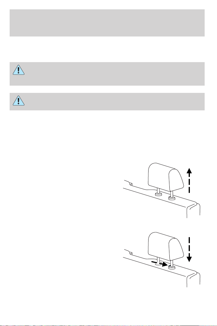
Seating and Safety Restraints
SEATING
Notes:
Reclining the seatback can cause an occupant to slide under the
seat’s safety belt, resulting in severe personal injuries in the
event of a collision.
Do not pile cargo higher than the seatbacks to reduce the risk of
injury in a collision or sudden stop.
Head restraints
The purpose of these head restraints is to help limit head motion in the
event of a rear collision. To properly adjust your head restraints, lift the
head restraint so that it is located directly behind your head or as close
to that position as possible.
The head restraints can be moved
up and down. Lift the head restraint
so that it is located directly or as
close as possible behind your head.
Push control to lower head restraint.
85
Page 86
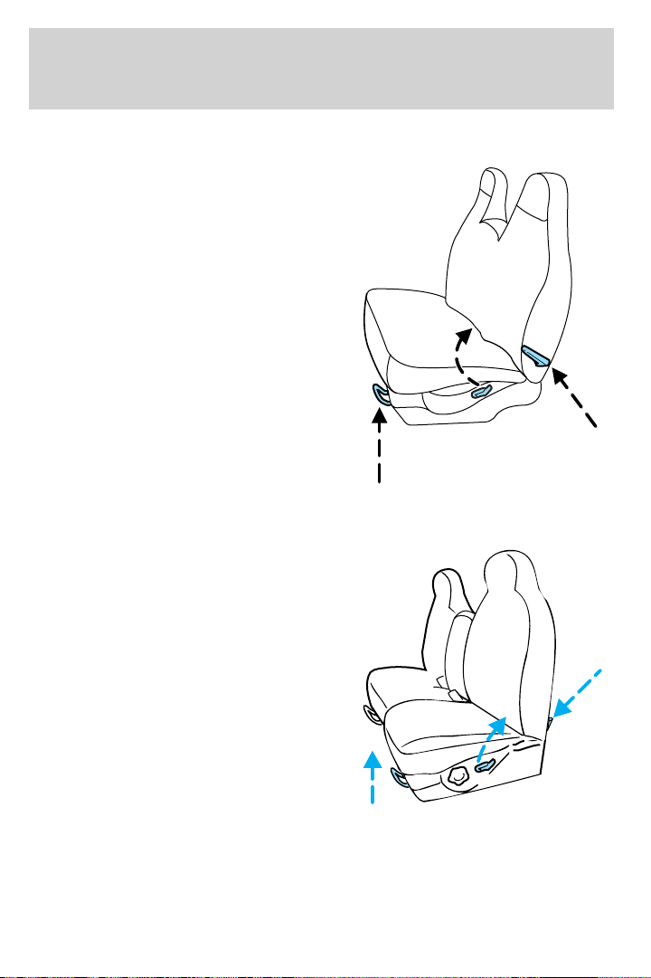
Seating and Safety Restraints
Full bench seat (if equipped)
• Lift the release bar to move the
seat forward or backward. Ensure
that the seat is relatched into
place.
• Pull up on the lever located at
the bottom of the seatback to
quickly fold the seatback forward.
• Pull up on the lever located at
the side of the seat cushion to
recline the seatback and to return
the seat to the upright position.
40/20/40 split bench seat (if equipped)
• Lift the track release bar to move
the seat forward or backward.
Ensure the seat is relatched into
place.
• Pull the handle on the side of the
seat up to recline the seat.
• Push down the lever located at
the bottom of the seatback to
quickly fold the seatback forward.
86
Page 87
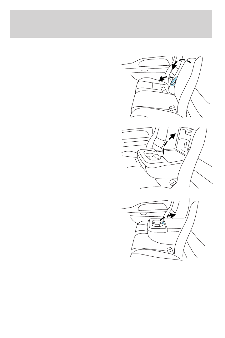
Seating and Safety Restraints
40/20/40 front seat armrest and console (if equipped)
To release the armrest, pull forward
on the strap and pull the armrest
down.
To gain access to the storage
compartment in your armrest, lift
the latch to open the lid. The lid
cannot be opened in the upright
position.
Lift up armrest to return it to a
center seatback.
87
Page 88
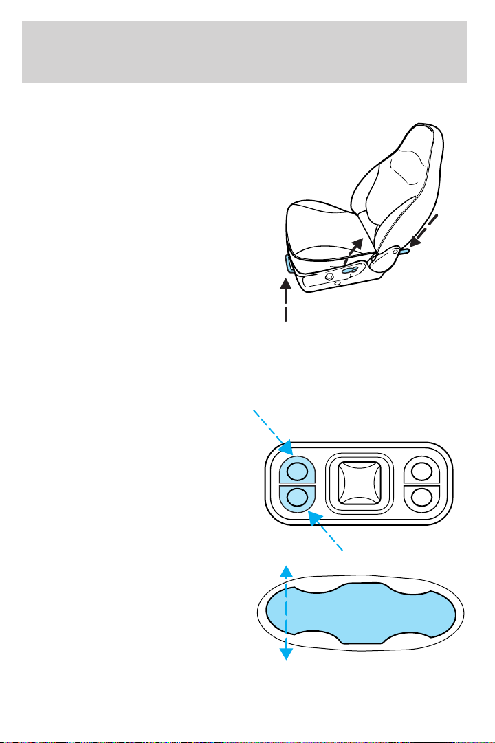
Seating and Safety Restraints
Captain’s chair (if equipped)
• Lift the bar to move the seat
forward or rearward. Make sure
that the seat is relatched into
place.
• To recline the seatback, pull the
release lever handle located on
the side of the seat up.
• Push down the lever (if
equipped) located at the bottom
of the seatback to quickly fold the
seatback forward.
Adjusting the front power seat (if equipped)
The control is located on the outboard side of the seat cushion.
Your vehicle will only be equipped with one of the two controls shown.
Press to raise or lower the front
portion of the seat cushion.
• Type A
• Type B
88
Page 89
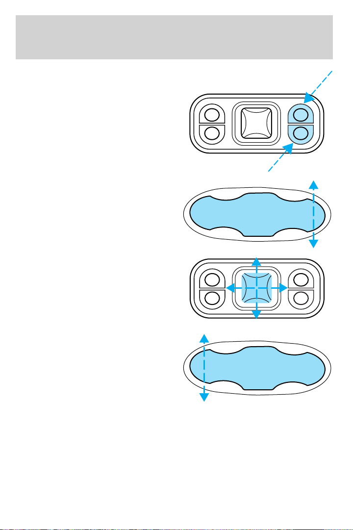
Seating and Safety Restraints
Press to raise or lower the rear
portion of the seat cushion.
• Type A
• Type B
• Type A
Press the control to move the seat
forward, backward, up or down.
• Type B
Press the control to move the seat
forward or backward.
89
Page 90
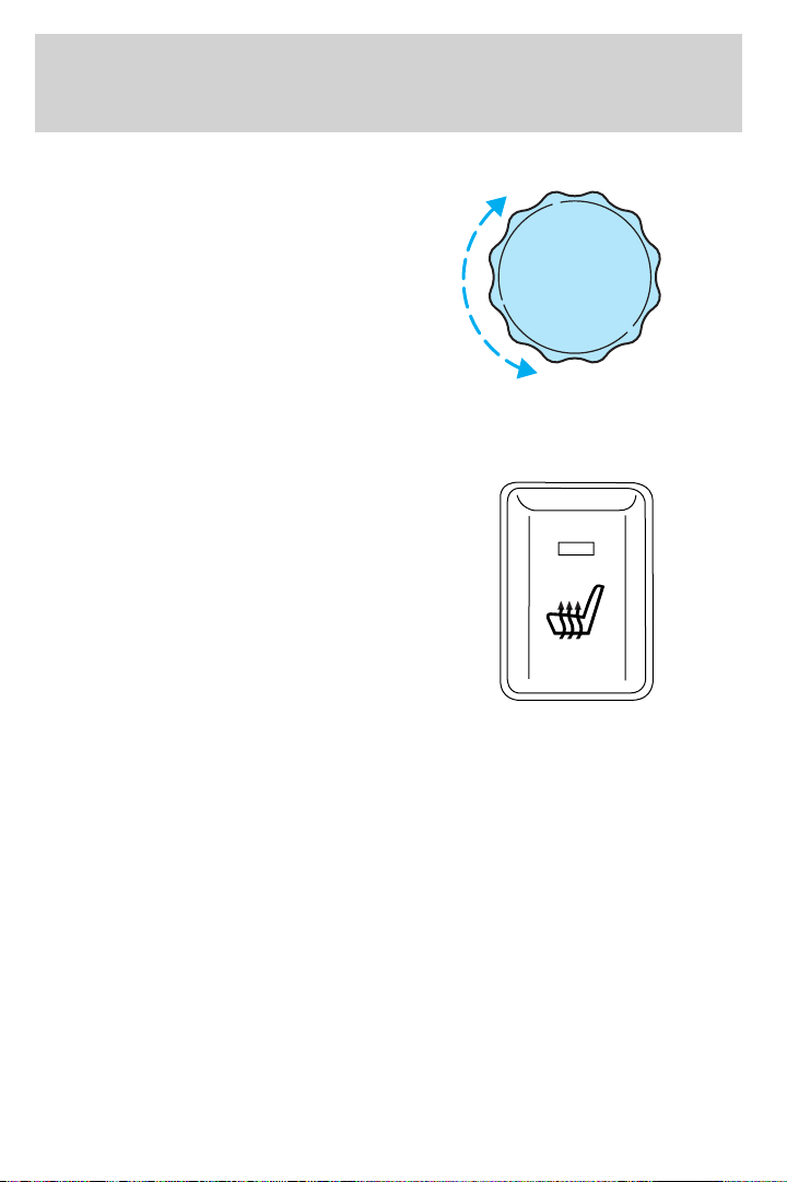
Seating and Safety Restraints
Using the manual lumbar support
For more lumbar support, turn the
lumbar support control toward the
front of vehicle.
For less lumbar support, turn the
lumbar support control toward the
rear of vehicle.
Heated seats (if equipped)
To operate the heated seats, do the following:
• Push control to activate.
• Push again to deactivate.
The indicator light on the control will illuminate when activated.
The system will not automatically shutoff unless control is pushed to
deactivate. If system is not manually terminated at last use, then system
will remain active at next ignition key cycle.
90
Page 91
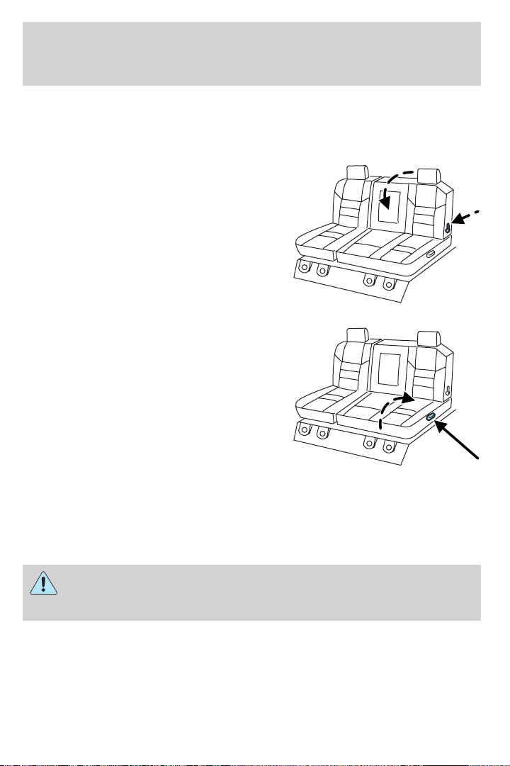
Seating and Safety Restraints
REAR FOLDING SEAT SYSTEM WITH LOAD FLOOR (IF EQUIPPED)
The rear seatback has a split 60/40 seat. Each seat cushion can be
flipped up into the seatback position.
1. Pull down the latch lever located
on the bottom seat back to fold the
seat back forward.
2. Pull up on the lever located on
the side of the seat cushion to
rotate the cushion up until it locks
into a vertical storage position,
gaining access to the grocery hook
located on the underside of the
driver-side seat cushion. The
maximum load is 25 lbs (11 kg).
Returning the seat to seating position
• Pull lever on the side of the seat to release seat cushion from storage
position.
• Push seat cushion down until it locks into horizontal position.
Always be sure that the seat is in a latched position, whether the
seat is occupied or empty. If not latched, the seat may cause
injury during a sudden stop.
91
Page 92
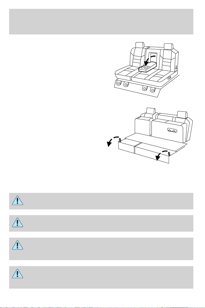
Seating and Safety Restraints
To gain access to the cupholders
and tray, pull down on the armrest.
To gain access to the 60/40 load
floor, store the cushion in the
upright locked position. Pull up on
the straps located at the sides of the
load floor, and rotate forward until
resting on the carpet.
SAFETY RESTRAINTS
Safety restraints precautions
Always drive and ride with your seatback upright and the lap
belt snug and low across the hips.
To reduce the risk of injury, make sure children sit in the back
seat where they can be properly restrained.
Never let a passenger hold a child on his or her lap while the
vehicle is moving. The passenger cannot protect the child from
injury in a collision.
All occupants of the vehicle, including the driver, should always
properly wear their safety belts, even when an air bag
supplemental restraint system (SRS) is provided.
92
Page 93
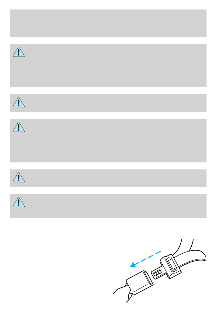
Seating and Safety Restraints
It is extremely dangerous to ride in a cargo area, inside or
outside of a vehicle. In a collision, people riding in these areas
are more likely to be seriously injured or killed. Do not allow people to
ride in any area of your vehicle that is not equipped with seats and
safety belts. Be sure everyone in your vehicle is in a seat and using a
safety belt properly.
In a rollover crash, an unbelted person is significantly more likely
to die than a person wearing a safety belt.
Each seating position in your vehicle has a specific safety belt
assembly which is made up of one buckle and one tongue that
are designed to be used as a pair. 1) Use the shoulder belt on the
outside shoulder only. Never wear the shoulder belt under the arm. 2)
Never swing the safety belt around your neck over the inside shoulder.
3) Never use a single belt for more than one person.
Always transport children 12 years old and under in the back
seat and always properly use appropriate child restraints.
Safety belts and seats can become hot in a vehicle that has been
closed up in sunny weather; they could burn a small child. Check
seat covers and buckles before you place a child anywhere near them.
Combination lap and shoulder belts
1. Insert the belt tongue into the
proper buckle (the buckle closest to
the direction the tongue is coming
from) until you hear a snap and feel
it latch. Make sure the tongue is
securely fastened in the buckle.
93
Page 94
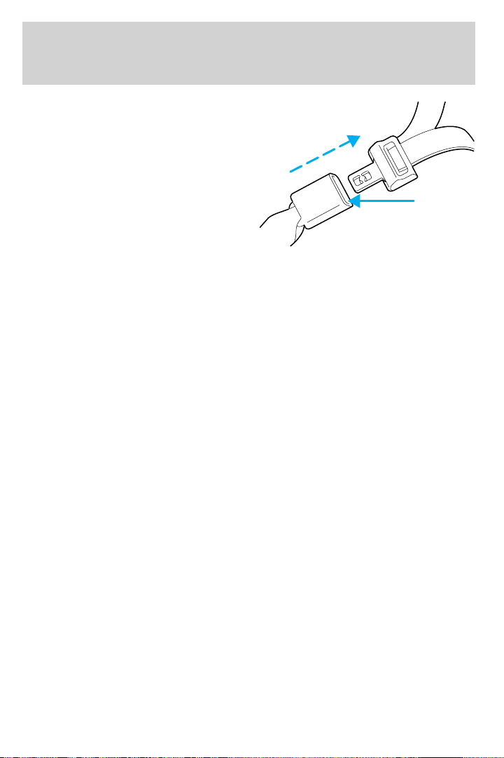
Seating and Safety Restraints
2. To unfasten, push the release
button and remove the tongue from
the buckle.
The front outboard and rear outboard safety restraints in the vehicle are
combination lap and shoulder belts. The front outboard passenger and
rear seat outboard safety belts have two types of locking modes
described below:
Vehicle sensitive mode
This is the normal retractor mode, which allows free shoulder belt length
adjustment to your movements and locking in response to vehicle
movement. For example, if the driver brakes suddenly or turns a corner
sharply, or the vehicle receives an impact of approximately 5 mph (8
km/h) or more, the combination safety belts will lock to help reduce
forward movement of the driver and passengers.
On SuperCab and Crew Cab models, the front seat belt system can also
be made to lock manually by quickly pulling on the shoulder belt.
Rear seat belts (if equipped) cannot be made to lock up by pulling
quickly on the belt.
Automatic locking mode
The automatic locking mode is not available on the driver safety belt.
When to use the automatic locking mode
In this mode, the shoulder belt is automatically pre-locked. The belt will
still retract to remove any slack in the shoulder belt. The automatic
locking mode is not available on the driver safety belt.
This mode should be used any time a child safety seat is installed in a
passenger front or outboard rear seating position (if equipped). Children
12 years old and under should be properly restrained in the rear seat
whenever possible. Refer to Safety restraints for children or Safety
seats for children later in this chapter.
94
Page 95
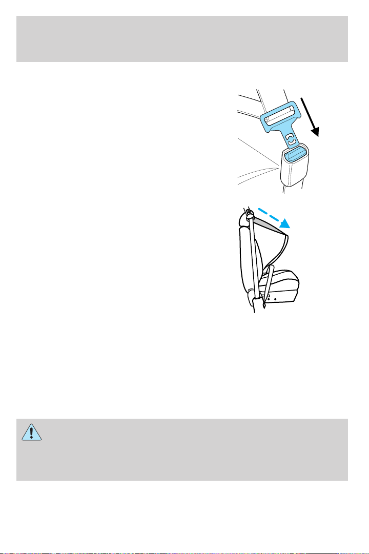
Seating and Safety Restraints
How to use the automatic locking mode
• Buckle the combination lap and
shoulder belt.
• Grasp the shoulder portion and
pull downward until the entire
belt is pulled out.
• Allow the belt to retract. As the belt retracts, you will hear a clicking
sound. This indicates the safety belt is now in the automatic locking
mode.
How to disengage the automatic locking mode
Disconnect the combination lap/shoulder belt and allow it to retract
completely to disengage the automatic locking mode and activate the
vehicle sensitive (emergency) locking mode.
After any vehicle collision, the front passenger and rear outboard
seat belt systems must be checked by a qualified technician to
verify that the “automatic locking retractor” feature for child seats is
still functioning properly. In addition, all seat belts should be checked
for proper function.
95
Page 96
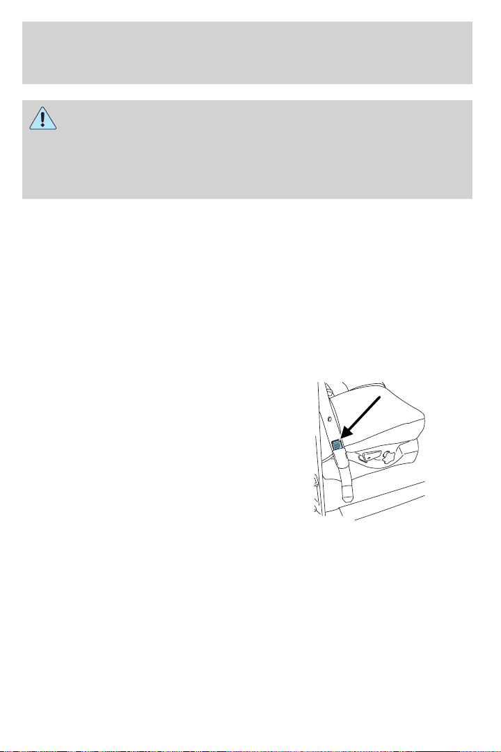
Seating and Safety Restraints
BELT AND RETRACTOR ASSEMBLY MUST BE REPLACED if
the seat belt assembly “automatic locking retractor” feature or
any other seat belt function is not operating properly when checked
according to the procedures in the Workshop Manual. Failure to
replace the belt and retractor assembly could increase the risk of
injury in collisions.
Energy Management Feature
• This vehicle has a seat belt system with an energy management
feature at the front outboard seating positions to help further reduce
the risk of injury in the event of a head-on collision.
• The front outboard seat belt systems have a retractor assembly that is
designed to pay out webbing in a controlled manner. This feature is
designed to help reduce the belt force acting on the occupant’s chest.
Safety belt replacement label
The short plastic boot on the front
safety belt at the passenger
outboard anchor location covers a
“Replace Belt” label on the safety
belt.
96
Page 97
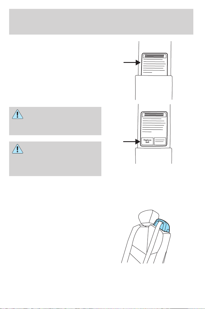
Seating and Safety Restraints
In the event of a collision, the
colored label (REPLACE BELT)
may become visible. If this occurs,
the safety belt must be replaced.
Whenever the yellow
portion of the label is
visible, the safety belt must be
replaced.
Failure to follow these
instructions will affect the
performance of the safety belts
and increase the risk of personal
injury.
Safety belt pretensioner
Your vehicle is equipped with safety belt pretensioners at the driver and
front outboard passenger seating positions.
If your front seat is a 40/20/40 or a
bucket seat, it is equipped with a
Seat Integrated Restraints
(SIR),which has shoulder belts
attached to the corners of the front
seat back. An SIR seat is equipped
with a buckle pretensioner. Do NOT
place objects between the seats, this
could interfere with the functioning
of the pretensioner. For the
SuperCab and Crew Cab base bench
seats and all Regular Cab seating positions, the safety belts are equipped
with a retractor pretensioner.
97
Page 98
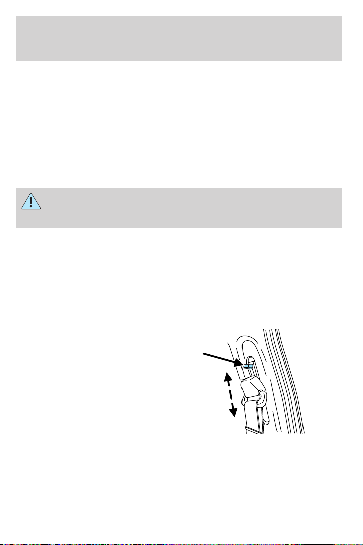
Seating and Safety Restraints
The driver and front outboard passenger safety belt pretensioners are
designed to activate only during certain frontal or near-frontal collisions
with sufficient longitudinal deceleration. A safety belt pretensioner is a
device which tightens the webbing of the lap and shoulder belts during
some collisions in such a way that they fit more snugly against the body.
The driver and front outboard passenger safety belt system (including
retractors, buckles and height adjusters) must be replaced if the vehicle
is involved in a collision that results in the activation of the safety belt
pretensioners. Refer to the Safety belt maintenance section in this
chapter.
Failure to replace the safety belt assembly under the above
conditions could result in severe personal injuries in the event of
a collision.
Front safety belt height adjustment
The front outboard seats are equipped with belt height adjusters.
If your vehicle is equipped with seat integrated restraints (SIR), you will
not have a safety belt height adjuster.
Adjust the height of the shoulder belt so the belt rests across the middle
of your shoulder.
• Regular Cab and 4–door Crew
Cab
98
Page 99
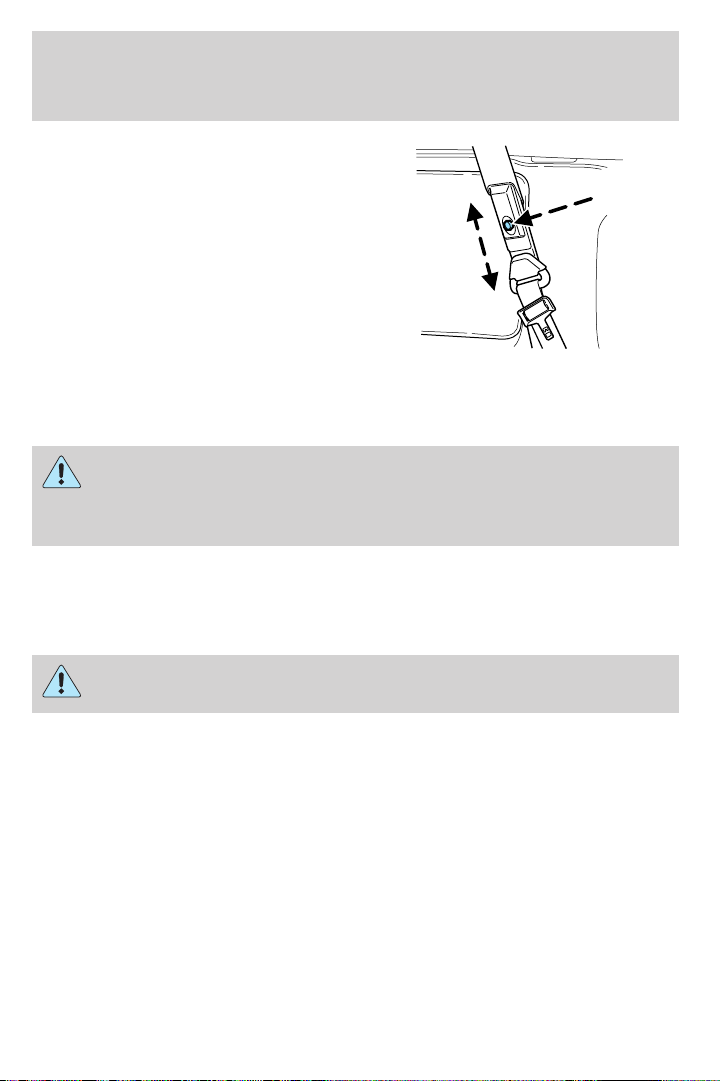
Seating and Safety Restraints
• 4–door Super Cab (if equipped)
To adjust the shoulder belt height, push the button and slide the height
adjuster up or down. Release the button and pull down on the height
adjuster to make sure it is locked in place.
Position the safety belt height adjusters so that the belt rests
across the middle of your shoulder. Failure to adjust the safety
belt properly could reduce the effectiveness of the seat belt and
increase the risk of injury in a collision.
Lap belts
Adjusting the lap belt
The lap belt should fit snugly and as low as possible around the
hips, not across the waist.
• 1st row center seating position
The lap belt does not adjust automatically.
99
Page 100
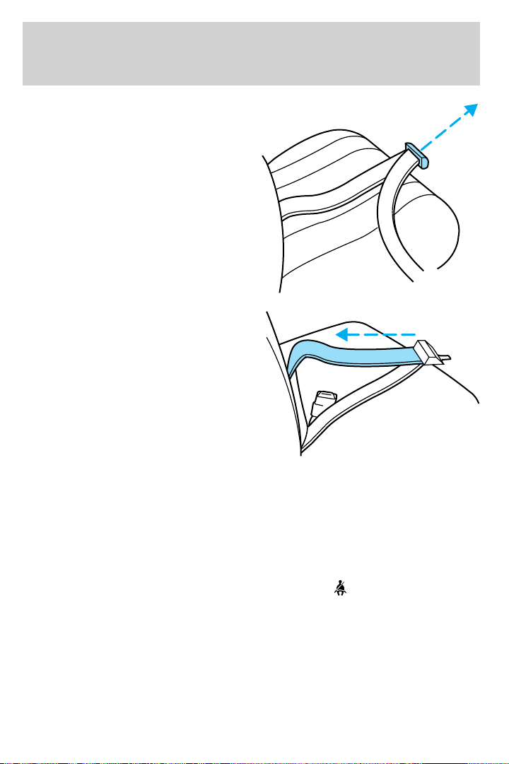
Seating and Safety Restraints
Insert the tongue into the correct
buckle (the buckle closest to the
direction the tongue is coming
from). To lengthen the belt, turn the
tongue at a right angle to the belt
and pull across your lap until it
reaches the buckle. To tighten the
belt, pull the loose end of the belt
through the tongue until it fits
snugly across the hips.
Shorten and fasten the belt when
not in use.
• 2nd row center seating position (if equipped)
The lap belt will not adjust automatically. To fasten, grasp the tongue,
and with a continuous motion, pull out enough webbing to buckle the
tongue into the correct buckle. If you did not pull out enough webbing to
reach the buckle, allow the tongue to retract fully before trying to pull it
out again.
Safety belt warning light and indicator chime
The safety belt warning light illuminates in the instrument cluster and a
chime sounds to remind the occupants to fasten their safety belts.
100
 Loading...