

Page 1

Factory Workshop Manual
Ford
Explorer Sport Trac 4wd
V8-4.6L VIN 8 (2007)
Anonymous
1st January 2018
Make
Model
Engine and year
This manual was submitted by
Date
Page 2
Ford Explorer Sport Trac 4wd Workshop Manual (V8-4.6L VIN 8 (2007))
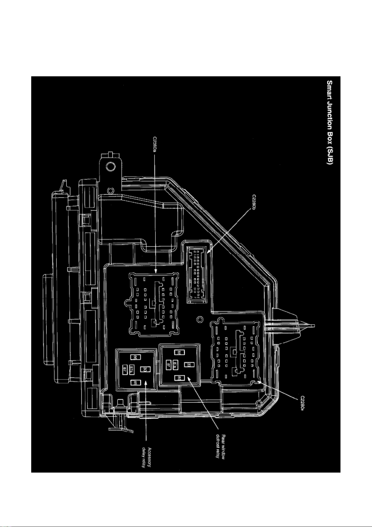
Ford Workshop Manuals > Relays and Modules > Relays and Modules - Accessories and Optional Equipment > Accessory
Delay Module > Accessory Delay Relay > Component Information > Locations
Page 3

Page 4
Ford Explorer Sport Trac 4wd Workshop Manual (V8-4.6L VIN 8 (2007))
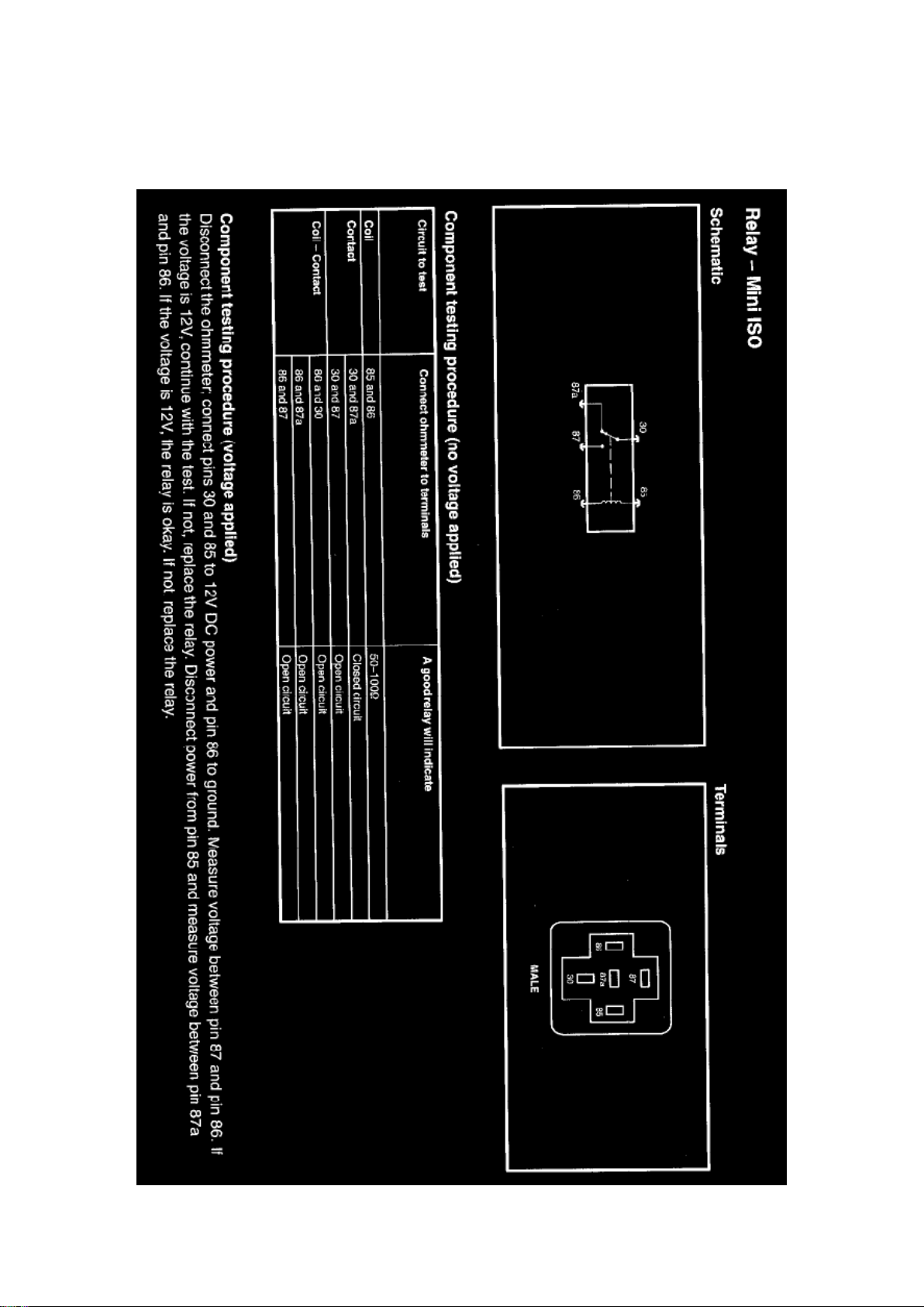
Ford Workshop Manuals > Relays and Modules > Relays and Modules - Accessories and Optional Equipment > Accessory
Delay Module > Accessory Delay Relay > Component Information > Locations > Page 8
Page 5

Page 6
Ford Explorer Sport Trac 4wd Workshop Manual (V8-4.6L VIN 8 (2007))
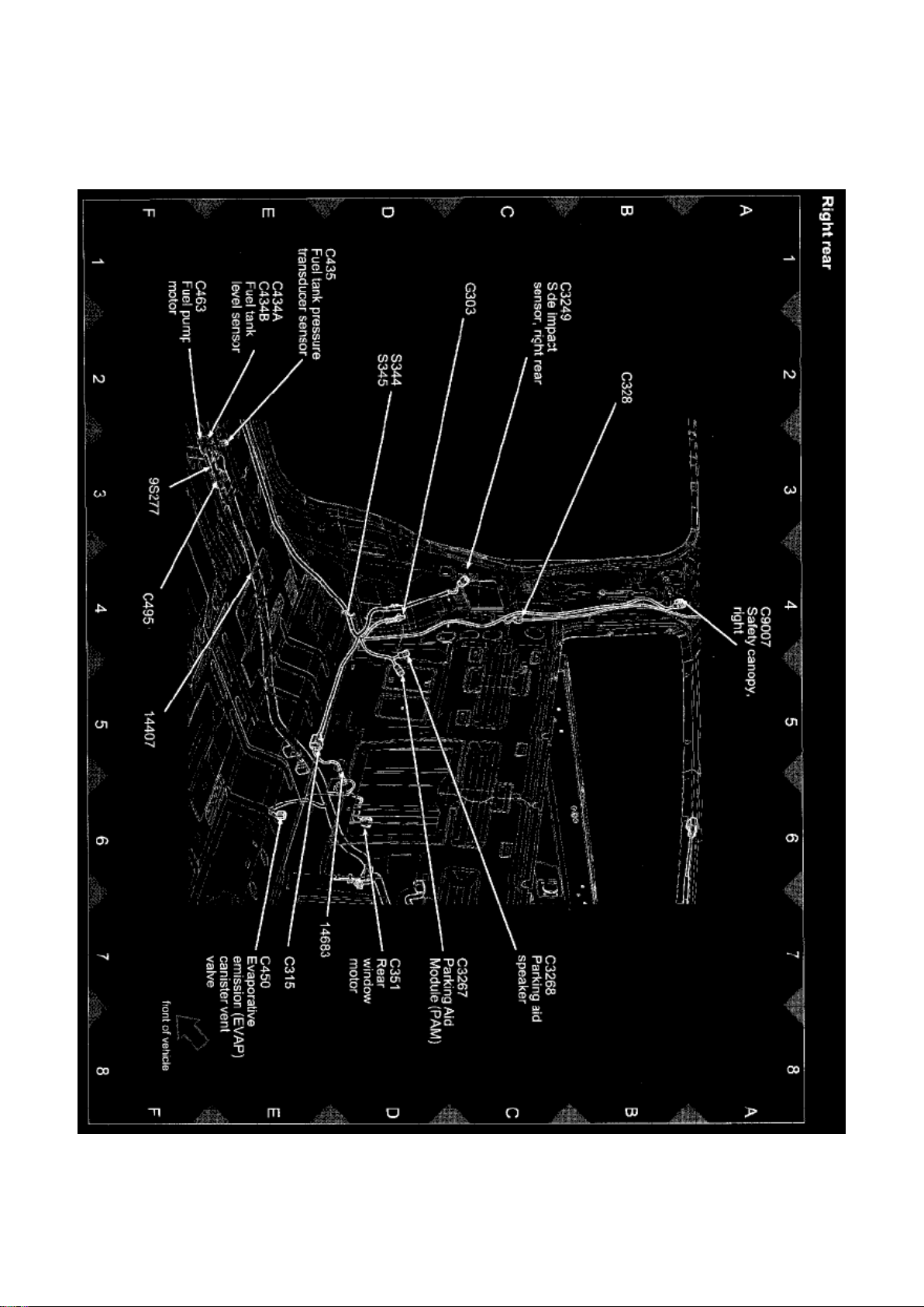
Ford Workshop Manuals > Relays and Modules > Relays and Modules - Accessories and Optional Equipment > Parking
Assist Control Module > Component Information > Locations
View 151-19 (Right Rear)
Page 7
Ford Explorer Sport Trac 4wd Workshop Manual (V8-4.6L VIN 8 (2007))
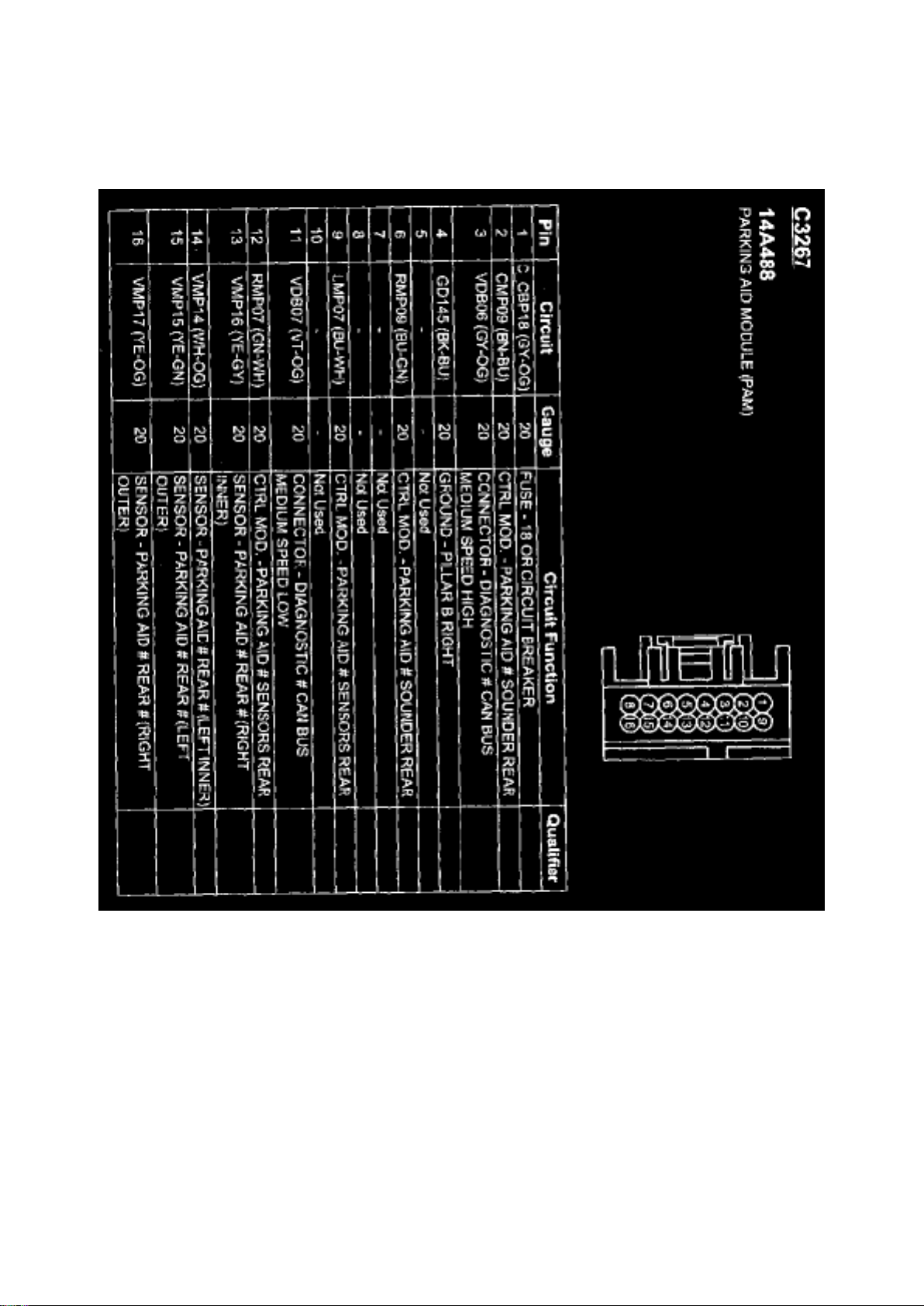
Ford Workshop Manuals > Relays and Modules > Relays and Modules - Accessories and Optional Equipment > Parking
Assist Control Module > Component Information > Locations > Page 12
C3267
Page 8
Ford Explorer Sport Trac 4wd Workshop Manual (V8-4.6L VIN 8 (2007))
Ford Workshop Manuals > Relays and Modules > Relays and Modules - Accessories and Optional Equipment > Parking
Assist Control Module > Component Information > Locations > Page 13
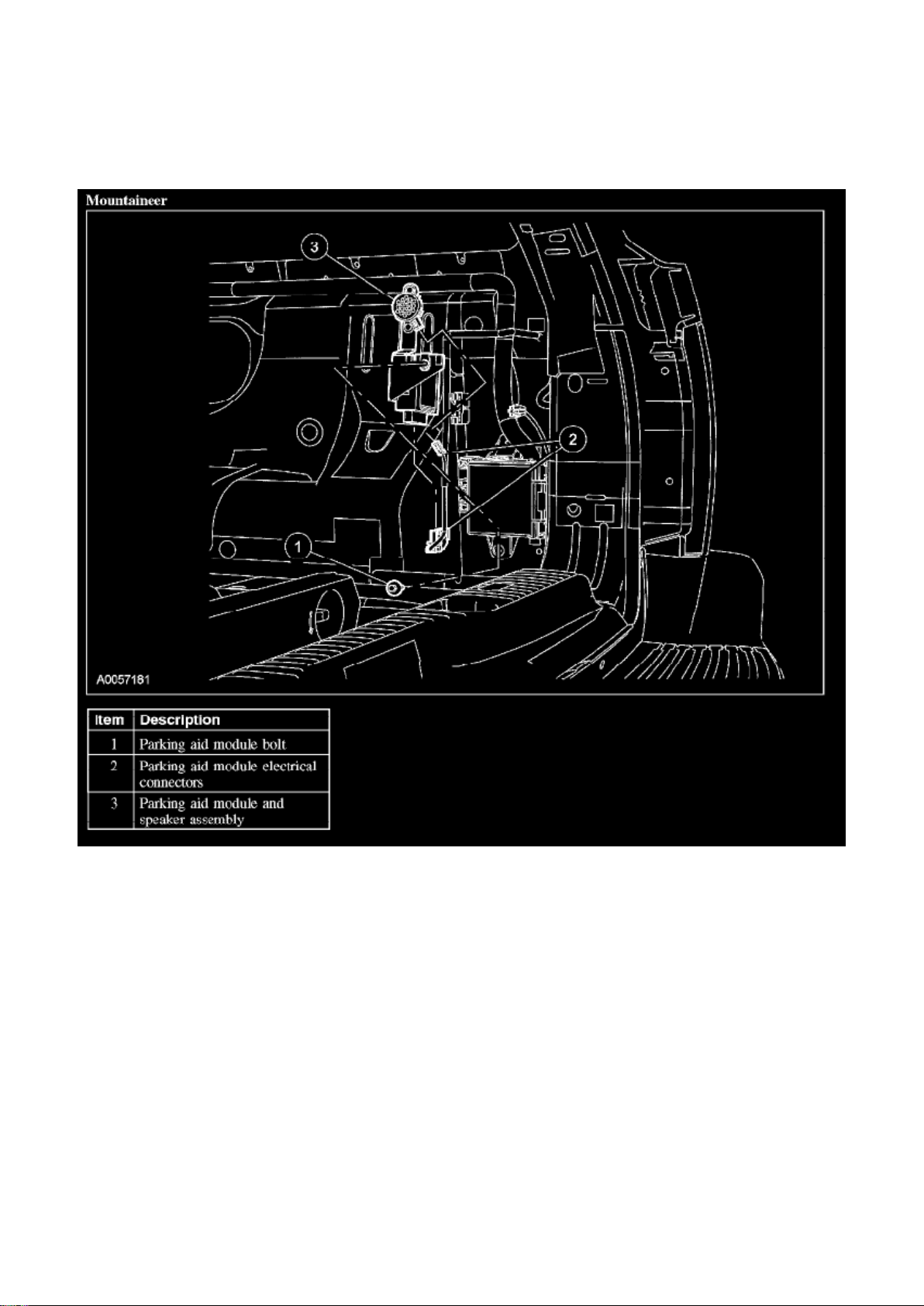
Parking Assist Control Module: Service and Repair
PARKING AID MODULE
Mountaineer
Page 9
Ford Explorer Sport Trac 4wd Workshop Manual (V8-4.6L VIN 8 (2007))
Ford Workshop Manuals > Relays and Modules > Relays and Modules - Accessories and Optional Equipment > Parking
Assist Control Module > Component Information > Locations > Page 14
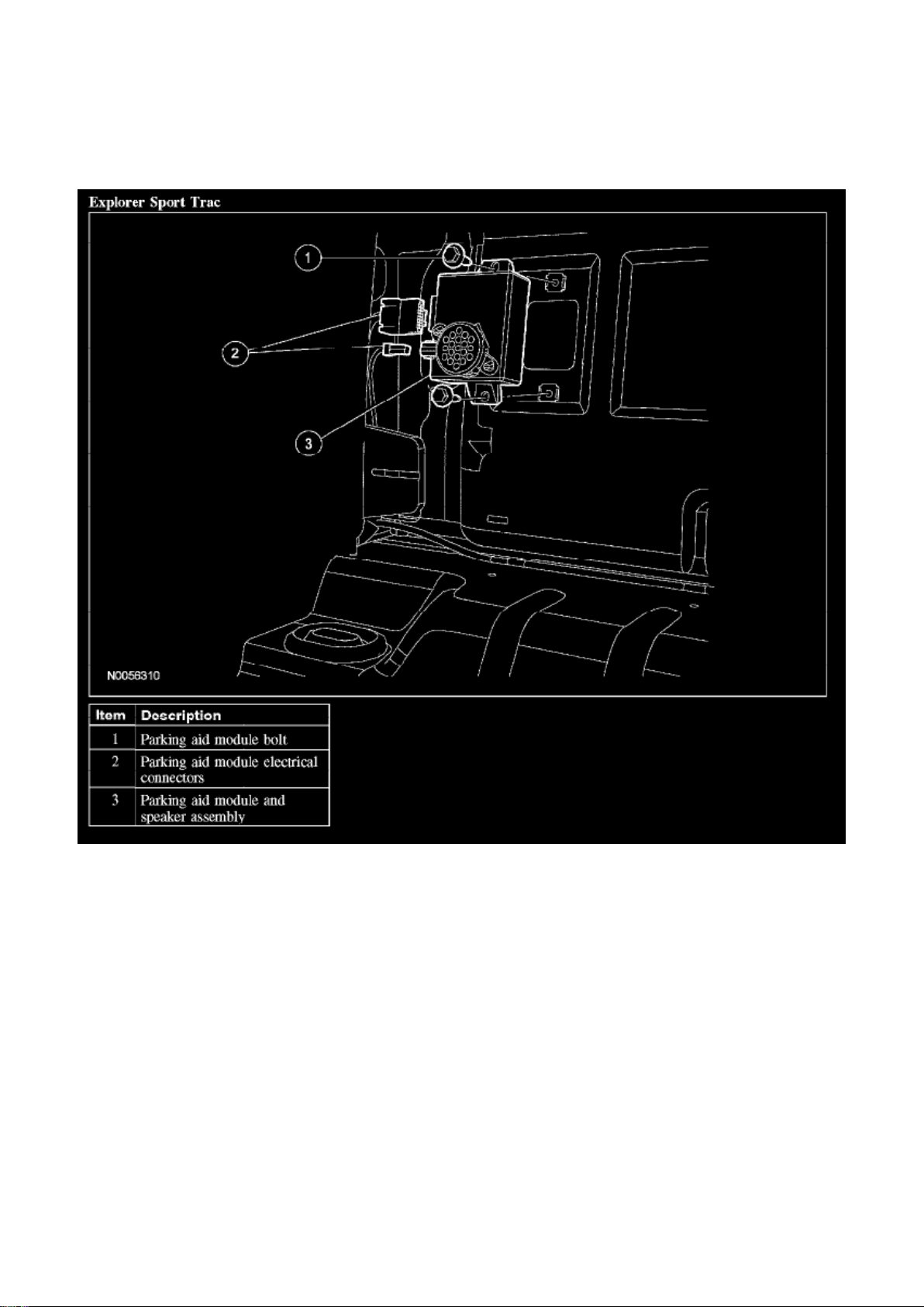
Explorer Sport Trac
Removal and Installation
Mountaineer
1. Remove the passenger rear quarter trim panel.
Explorer Sport Trac
2. Remove the cab rear trim panel.
All vehicles
3. Remove the bolt and the parking aid module.
- Disconnect the electrical connectors.
Page 10

4. To install, reverse the removal procedure.
Page 11

Ford Explorer Sport Trac 4wd Workshop Manual (V8-4.6L VIN 8 (2007))
Ford Workshop Manuals > Relays and Modules > Relays and Modules - Accessories and Optional Equipment > Pedal
Positioning Module > Component Information > Description and Operation
Page 12

Pedal Positioning Module: Description and Operation
Adjustable Pedals Using the adjustable pedal switch located on the instrument panel, the driver
can adjust the brake and accelerator pedals for a more comfortable driving position. For removal
and installation of the adjustable pedals, refer to Brake Pedal and Bracket.
Adjustable Pedal Operation The adjustable pedals with or without memory feature are operational
with the ignition switch in the ON or OFF position. The pedals are adjusted forward or rearward
using the adjustable pedal switch.
Memory Adjustable Pedal Operation The adjustable pedals with memory feature is controlled by
using the memory switches or the remote keyless entry (RKE) transmitter. The exterior mirror and
power driver seat positions are also stored and recalled with the power adjustable pedal positions.
The system can store 3 memory settings.
Driver Seat Module (DSM) The DSM controls the memory adjustable pedals.
The DSM constantly monitors the systems under its control and records concerns in the form of
diagnostic trouble codes (DTCs). A DTC can be retrieved with the scan tool through the data link
connector (DLC).
Page 13

Ford Explorer Sport Trac 4wd Workshop Manual (V8-4.6L VIN 8 (2007))
Ford Workshop Manuals > Relays and Modules > Relays and Modules - Body and Frame > Memory Positioning Module >
Component Information > Description and Operation
Page 14

Memory Positioning Module: Description and Operation
Memory Adjustable Pedal Operation The adjustable pedals with memory feature is controlled by
using the memory switches or the remote keyless entry (RKE) transmitter. The exterior mirror and
power driver seat positions are also stored and recalled with the power adjustable pedal positions.
The system can store 3 memory settings.
Driver Seat Module (DSM) The DSM controls the memory adjustable pedals.
The DSM constantly monitors the systems under its control and records concerns in the form of
diagnostic trouble codes (DTCs). A DTC can be retrieved with the scan tool through the data link
connector (DLC).
Memory Adjustable Pedal Operation The adjustable pedals with memory feature is controlled by
using the memory switches or the remote keyless entry (RKE) transmitter. The exterior mirror and
power driver seat positions are also stored and recalled with the power adjustable pedal positions.
The system can store 3 memory settings.
Page 15

Ford Explorer Sport Trac 4wd Workshop Manual (V8-4.6L VIN 8 (2007))
Ford Workshop Manuals > Relays and Modules > Relays and Modules - Body and Frame > Pedal Positioning Module >
Component Information > Description and Operation
Page 16

Pedal Positioning Module: Description and Operation
Adjustable Pedals Using the adjustable pedal switch located on the instrument panel, the driver
can adjust the brake and accelerator pedals for a more comfortable driving position. For removal
and installation of the adjustable pedals, refer to Brake Pedal and Bracket.
Adjustable Pedal Operation The adjustable pedals with or without memory feature are operational
with the ignition switch in the ON or OFF position. The pedals are adjusted forward or rearward
using the adjustable pedal switch.
Memory Adjustable Pedal Operation The adjustable pedals with memory feature is controlled by
using the memory switches or the remote keyless entry (RKE) transmitter. The exterior mirror and
power driver seat positions are also stored and recalled with the power adjustable pedal positions.
The system can store 3 memory settings.
Driver Seat Module (DSM) The DSM controls the memory adjustable pedals.
The DSM constantly monitors the systems under its control and records concerns in the form of
diagnostic trouble codes (DTCs). A DTC can be retrieved with the scan tool through the data link
connector (DLC).
Page 17
Ford Explorer Sport Trac 4wd Workshop Manual (V8-4.6L VIN 8 (2007))
Ford Workshop Manuals > Relays and Modules > Relays and Modules - Body and Frame > Auxiliary Step / Running Board
Module > Component Information > Service and Repair
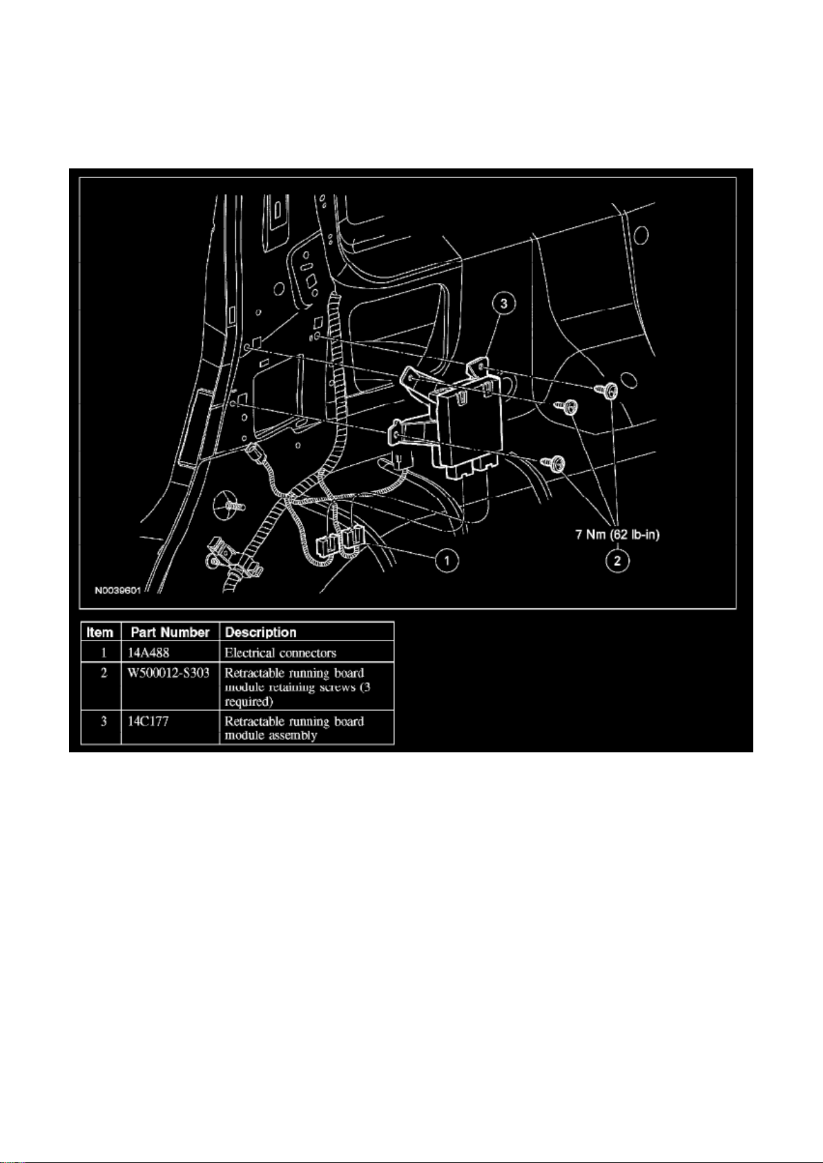
Auxiliary Step / Running Board Module: Service and Repair
RETRACTABLE RUNNING BOARD MODULE
Removal and Installation
1. Remove the RH C-pillar trim panel. 2. Disconnect the retractable running board module electrical
connectors. 3. Remove the 3 screws and the retractable running board module assembly.
- To install, tighten to 7 Nm (62 lb-in).
4. To install, reverse the removal procedure.
Page 18
Ford Explorer Sport Trac 4wd Workshop Manual (V8-4.6L VIN 8 (2007))
Ford Workshop Manuals > Relays and Modules > Relays and Modules - Body and Frame > Sunroof / Moonroof Module >
Component Information > Locations
Page 19

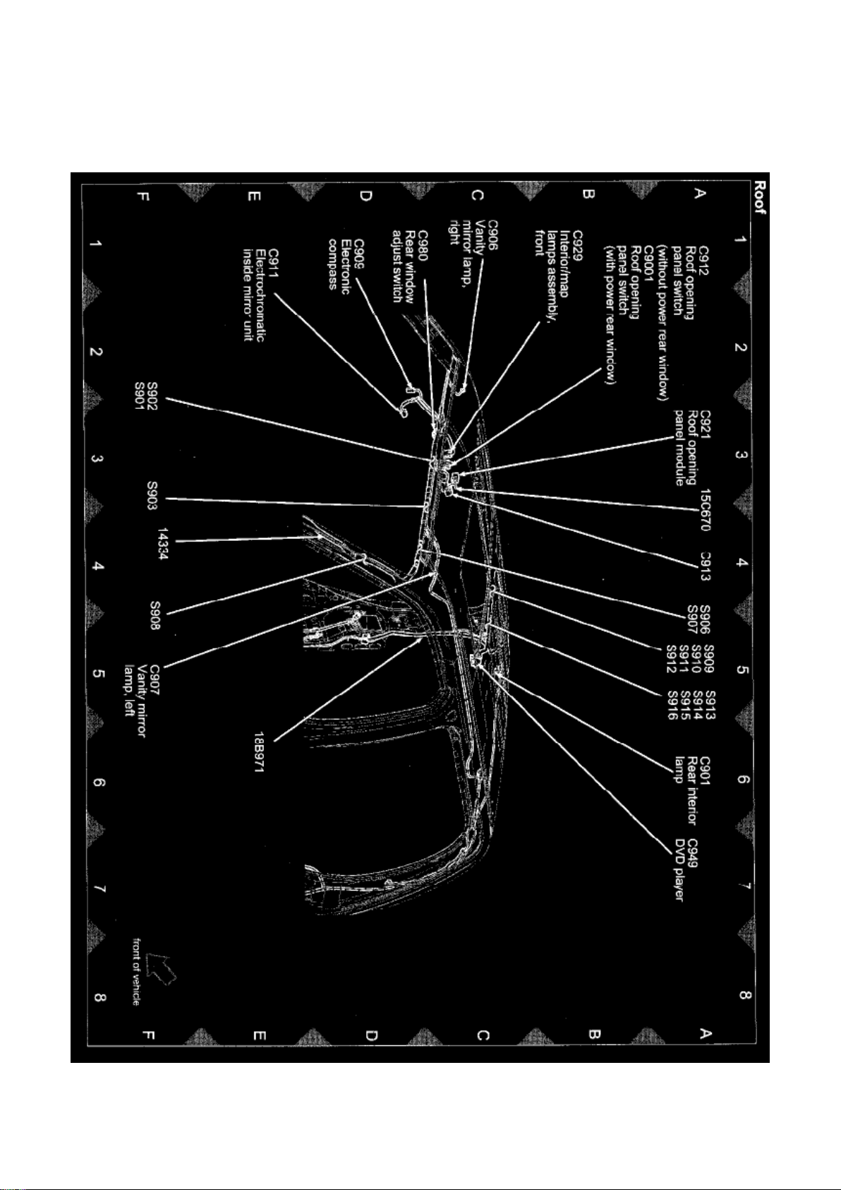
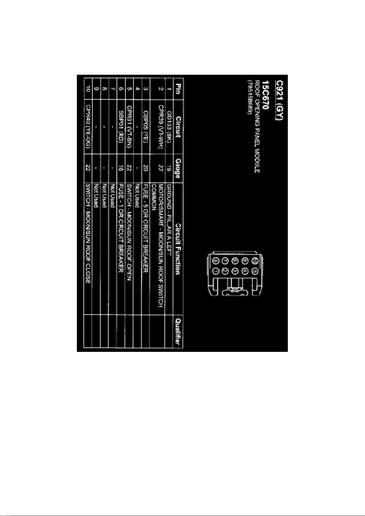
View 151-26 (Roof)
Page 20
Ford Explorer Sport Trac 4wd Workshop Manual (V8-4.6L VIN 8 (2007))
Ford Workshop Manuals > Relays and Modules > Relays and Modules - Body and Frame > Sunroof / Moonroof Module >
Component Information > Locations > Page 31
C921
Page 21
Ford Explorer Sport Trac 4wd Workshop Manual (V8-4.6L VIN 8 (2007))
Ford Workshop Manuals > Relays and Modules > Relays and Modules - Body and Frame > Trailer Towing Relay >
Component Information > Locations
Page 22

Page 23
Ford Explorer Sport Trac 4wd Workshop Manual (V8-4.6L VIN 8 (2007))
Ford Workshop Manuals > Relays and Modules > Relays and Modules - Body and Frame > Trailer Towing Relay >
Component Information > Locations > Page 35
Page 24

Page 25
Ford Explorer Sport Trac 4wd Workshop Manual (V8-4.6L VIN 8 (2007))
Ford Workshop Manuals > Relays and Modules > Relays and Modules - Brakes and Traction Control > Electronic Brake
Control Module > Component Information > Technical Service Bulletins > Customer Interest for Electronic Brake Control
Module: > 06-6-9 > Apr > 06 > ABS/TCS/RCS - Warning Lamp ON/DTC C1440 Set
Electronic Brake Control Module: Customer Interest ABS/TCS/RCS - Warning Lamp ON/DTC
C1440 Set
TSB 06-6-9
04/03/06
ANTI-LOCK BRAKE SYSTEM / TRACTION CONTROL / ROLL STABILITY CONTROL
INDICATOR (ABS / TC / RSC) WARNING LAMP ON WITH DTC C1440
FORD: 2006 Explorer 2007 Explorer Sport Trac
MERCURY: 2006 Mountaineer
ISSUE Some 2006 Explorer 4dr / Mountaineer and 2007 Sport Trac vehicles built through
3/16/2006 may exhibit an anti-lock brake system / traction control / roll stability control (ABS / TC /
RSC light) warning lamp illuminated with diagnostic trouble code C1440 pressure transducer main /
primary signal faulted. This may be caused by the integrated control unit (ICU).
ACTION Follow the Service Procedure to determine if the ABS module needs to be replaced.
NOTE
THE BASE BRAKE SYSTEM CONTINUES TO FUNCTION PROPERLY.
SERVICE PROCEDURE
1. Install scan tool, retrieve DTCs and record.
a. If DTC C1440 is retrieved, proceed to Step 2.
b. If DTC C1440 is not retrieved, this TSB does not apply. Proceed with normal diagnostics.
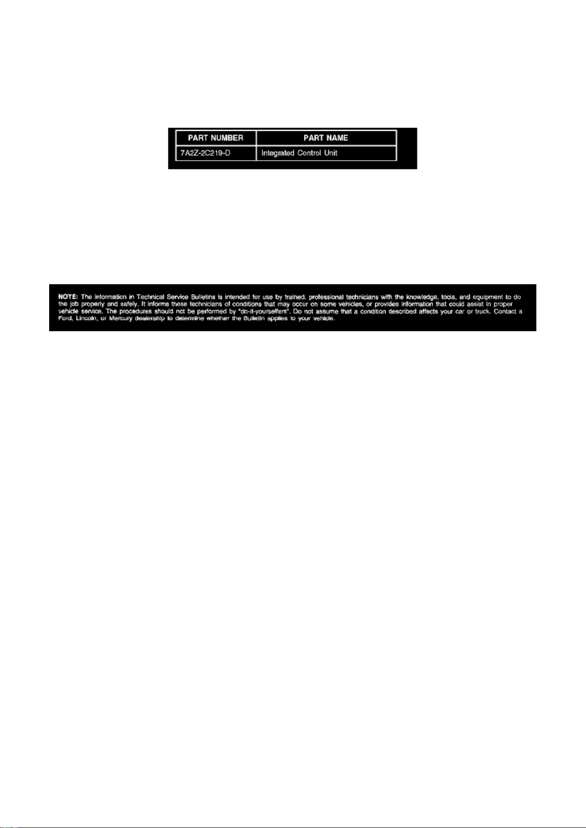
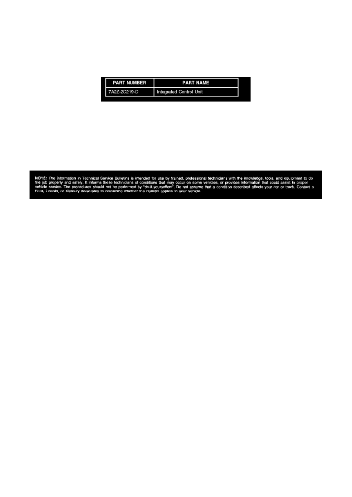
2. Replace the ABS module (2C219). Refer to Workshop Manual, Section 206-09 for Removal and
Installation procedure.
Page 26

Parts Block
WARRANTY STATUS: Eligible Under Provisions Of New Vehicle Limited Warranty Coverage
DEALER CODING
CONDITION
BASIC PART NO. CODE
2C219 42
Disclaimer
Page 27
Ford Explorer Sport Trac 4wd Workshop Manual (V8-4.6L VIN 8 (2007))
Ford Workshop Manuals > Relays and Modules > Relays and Modules - Brakes and Traction Control > Electronic Brake
Control Module > Component Information > Technical Service Bulletins > All Technical Service Bulletins for Electronic
Brake Control Module: > 06-6-9 > Apr > 06 > ABS/TCS/RCS - Warning Lamp ON/DTC C1440 Set
Electronic Brake Control Module: All Technical Service Bulletins ABS/TCS/RCS - Warning Lamp
ON/DTC C1440 Set
TSB 06-6-9
04/03/06
ANTI-LOCK BRAKE SYSTEM / TRACTION CONTROL / ROLL STABILITY CONTROL
INDICATOR (ABS / TC / RSC) WARNING LAMP ON WITH DTC C1440
FORD: 2006 Explorer 2007 Explorer Sport Trac
MERCURY: 2006 Mountaineer
ISSUE Some 2006 Explorer 4dr / Mountaineer and 2007 Sport Trac vehicles built through
3/16/2006 may exhibit an anti-lock brake system / traction control / roll stability control (ABS / TC /
RSC light) warning lamp illuminated with diagnostic trouble code C1440 pressure transducer main /
primary signal faulted. This may be caused by the integrated control unit (ICU).
ACTION Follow the Service Procedure to determine if the ABS module needs to be replaced.
NOTE
THE BASE BRAKE SYSTEM CONTINUES TO FUNCTION PROPERLY.
SERVICE PROCEDURE
1. Install scan tool, retrieve DTCs and record.
a. If DTC C1440 is retrieved, proceed to Step 2.
b. If DTC C1440 is not retrieved, this TSB does not apply. Proceed with normal diagnostics.
2. Replace the ABS module (2C219). Refer to Workshop Manual, Section 206-09 for Removal and
Installation procedure.
Page 28

Parts Block
WARRANTY STATUS: Eligible Under Provisions Of New Vehicle Limited Warranty Coverage
DEALER CODING
CONDITION
BASIC PART NO. CODE
2C219 42
Disclaimer
Page 29
Ford Explorer Sport Trac 4wd Workshop Manual (V8-4.6L VIN 8 (2007))
Ford Workshop Manuals > Relays and Modules > Relays and Modules - Brakes and Traction Control > Electronic Brake
Control Module > Component Information > Technical Service Bulletins > Page 50
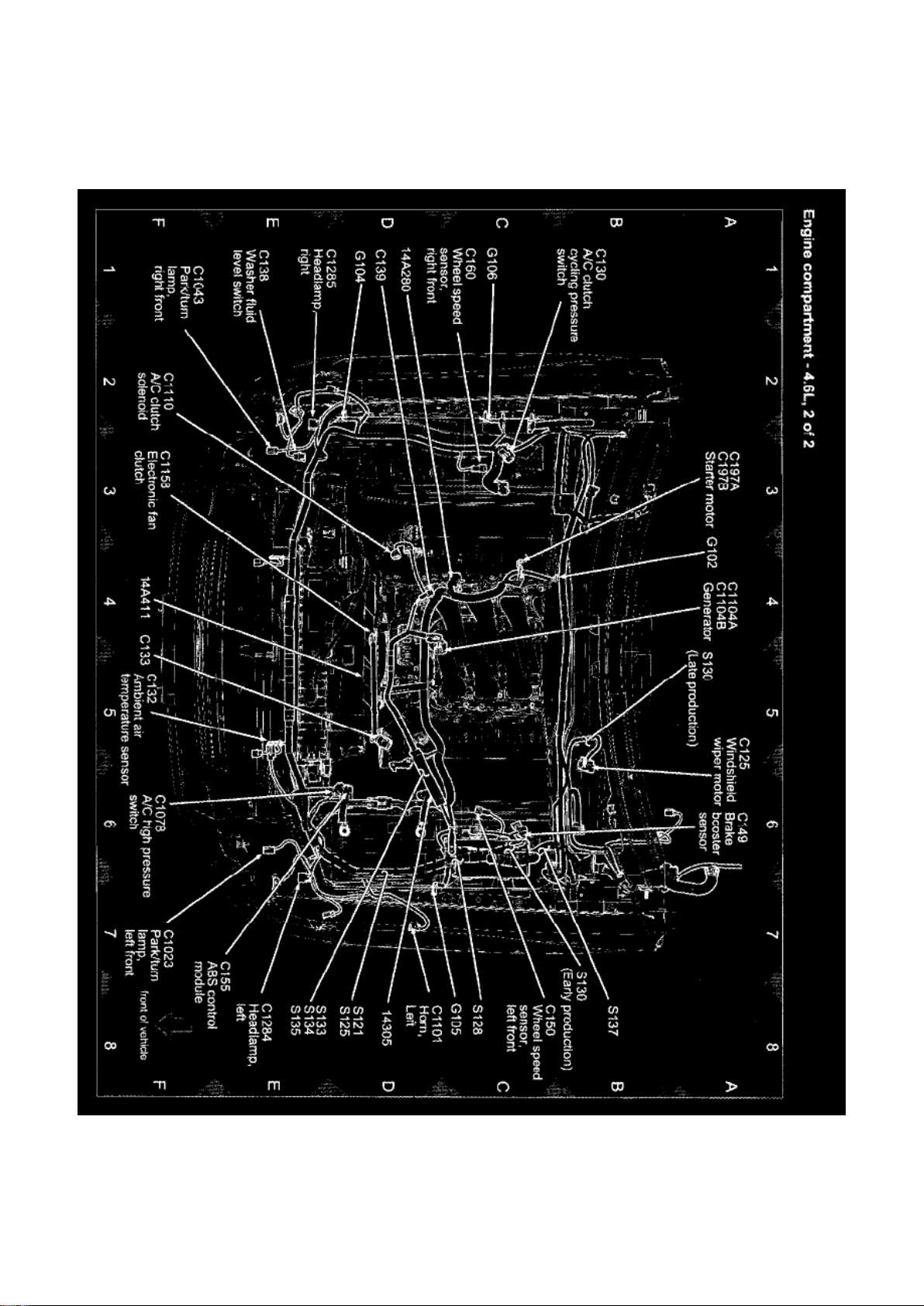
View 151-4 (Engine Compartment - 4.6L, 2 Of 2)
Page 30
Ford Explorer Sport Trac 4wd Workshop Manual (V8-4.6L VIN 8 (2007))
Ford Workshop Manuals > Relays and Modules > Relays and Modules - Brakes and Traction Control > Electronic Brake
Control Module > Component Information > Technical Service Bulletins > Page 51
Page 31

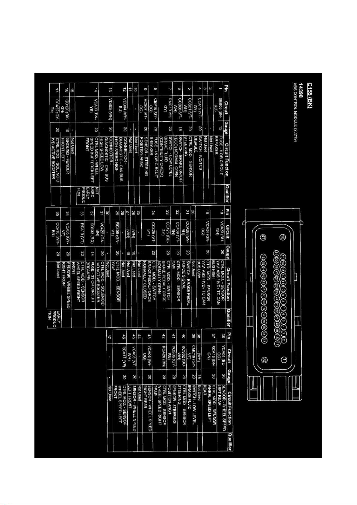
C155
Page 32
Ford Explorer Sport Trac 4wd Workshop Manual (V8-4.6L VIN 8 (2007))
Ford Workshop Manuals > Relays and Modules > Relays and Modules - Brakes and Traction Control > Electronic Brake
Control Module > Component Information > Technical Service Bulletins > Page 52
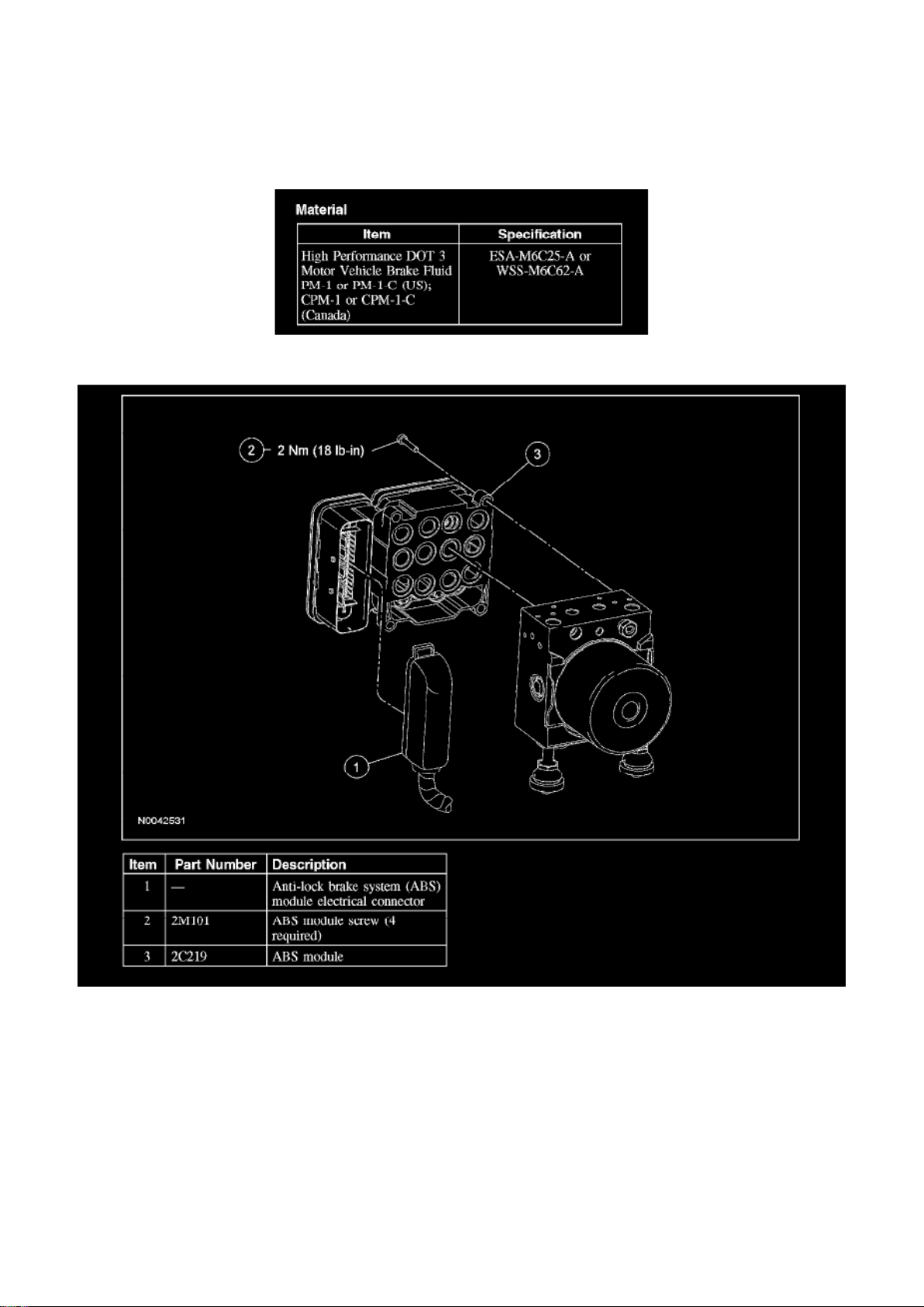
Electronic Brake Control Module: Service and Repair
Anti-Lock Brake System (ABS) Module
Material
Removal and Installation
Page 33

WARNING: Carefully read cautionary information on product label. For EMERGENCY MEDICAL
INFORMATION seek medical advice. In the USA or Canada on Ford/Motorcraft products call:
1-800-959-3673. For additional information, consult the product Material Safety Data Sheet
(MSDS) if available. Failure to follow these instructions may result in personal injury.
CAUTION: Brake fluid is harmful to painted and plastic surfaces. If brake fluid is spilled onto a
painted or plastic surface, immediately wash it with water.
CAUTION: Electronic modules are sensitive to electrical charges. The ABS module can be
damaged if exposed to these charges.
NOTE: When installing a new ABS module, it must be configured (using vehicle as-built data) and
calibrated. Follow the scan tool directions for the calibration procedures. For module configuration,
refer to Information Bus.
Page 34

Ford Explorer Sport Trac 4wd Workshop Manual (V8-4.6L VIN 8 (2007))
Ford Workshop Manuals > Relays and Modules > Relays and Modules - Brakes and Traction Control > Electronic Brake
Control Module > Component Information > Technical Service Bulletins > Page 53
Page 35

1. Remove the hydraulic control unit (HCU).
2. CAUTION: Make sure that the ABS module is properly seated to the HCU and that the torque of
the ABS module screws is correct, or
damage to the components can occur.
Remove the 4 screws and the ABS module. ^
To install, tighten to 2 Nm (18 inch lbs.).
3. To install, reverse the removal procedure.
Page 36
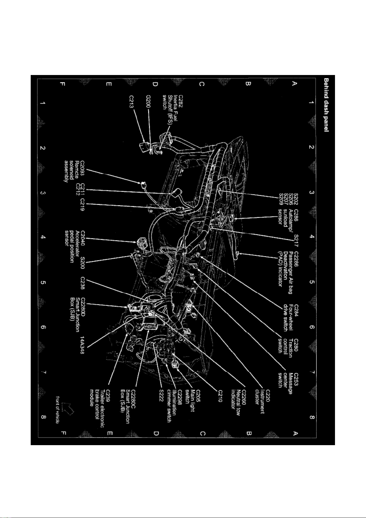
Ford Explorer Sport Trac 4wd Workshop Manual (V8-4.6L VIN 8 (2007))
Ford Workshop Manuals > Relays and Modules > Relays and Modules - Brakes and Traction Control > Trailer Brake
Control Module > Component Information > Locations
View 151-12 (behind Dash Panel)
Page 37
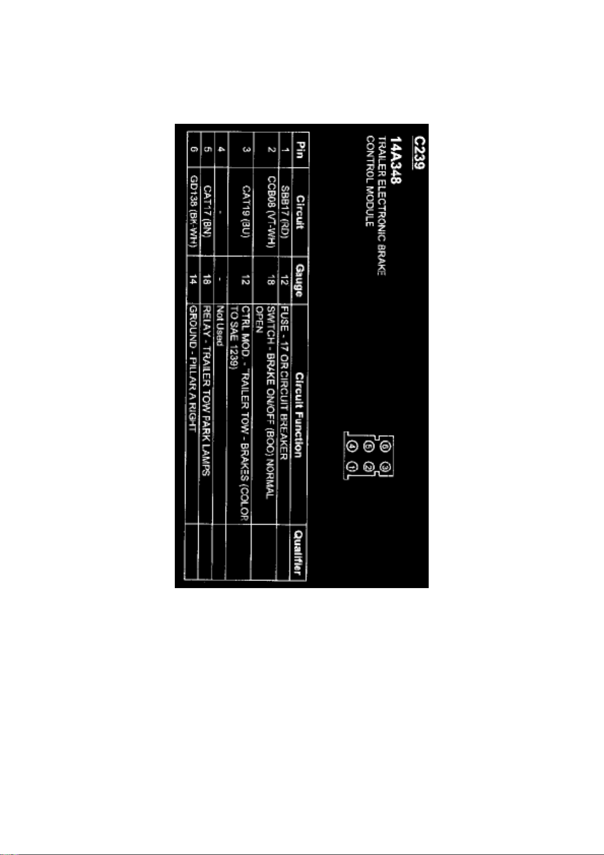
Ford Explorer Sport Trac 4wd Workshop Manual (V8-4.6L VIN 8 (2007))
Ford Workshop Manuals > Relays and Modules > Relays and Modules - Brakes and Traction Control > Trailer Brake
Control Module > Component Information > Locations > Page 57
C239
Page 38
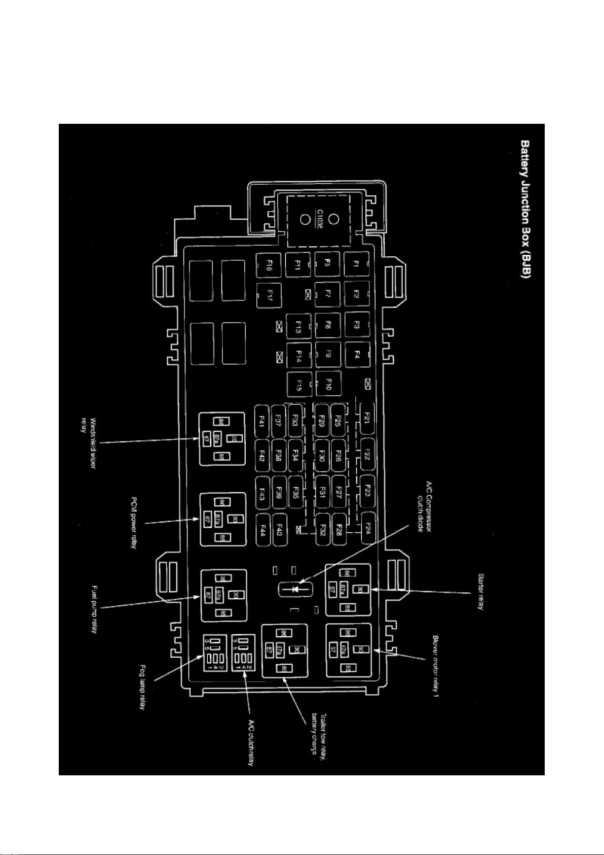
Ford Explorer Sport Trac 4wd Workshop Manual (V8-4.6L VIN 8 (2007))
Ford Workshop Manuals > Relays and Modules > Relays and Modules - HVAC > Blower Motor Relay > Component
Information > Locations > Blower Motor Relay 1
Page 39

Page 40
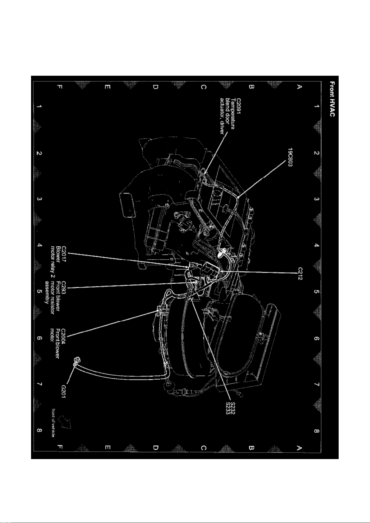
Ford Explorer Sport Trac 4wd Workshop Manual (V8-4.6L VIN 8 (2007))
Ford Workshop Manuals > Relays and Modules > Relays and Modules - HVAC > Blower Motor Relay > Component
Information > Locations > Blower Motor Relay 1 > Page 63
Page 41

View 151-10 (Front HVAC)
Page 42
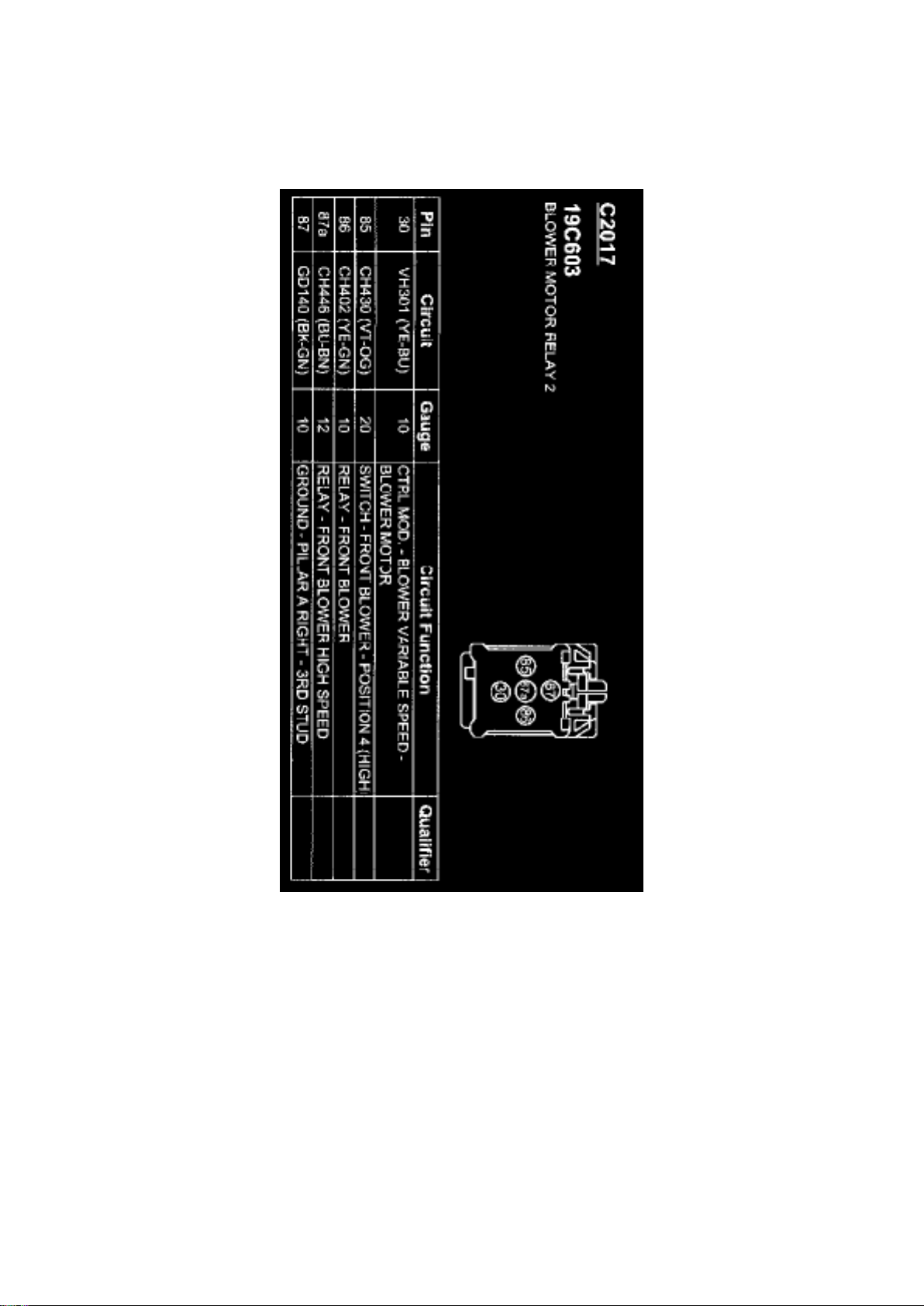
Ford Explorer Sport Trac 4wd Workshop Manual (V8-4.6L VIN 8 (2007))
Ford Workshop Manuals > Relays and Modules > Relays and Modules - HVAC > Blower Motor Relay > Component
Information > Locations > Page 64
C2017
Page 43
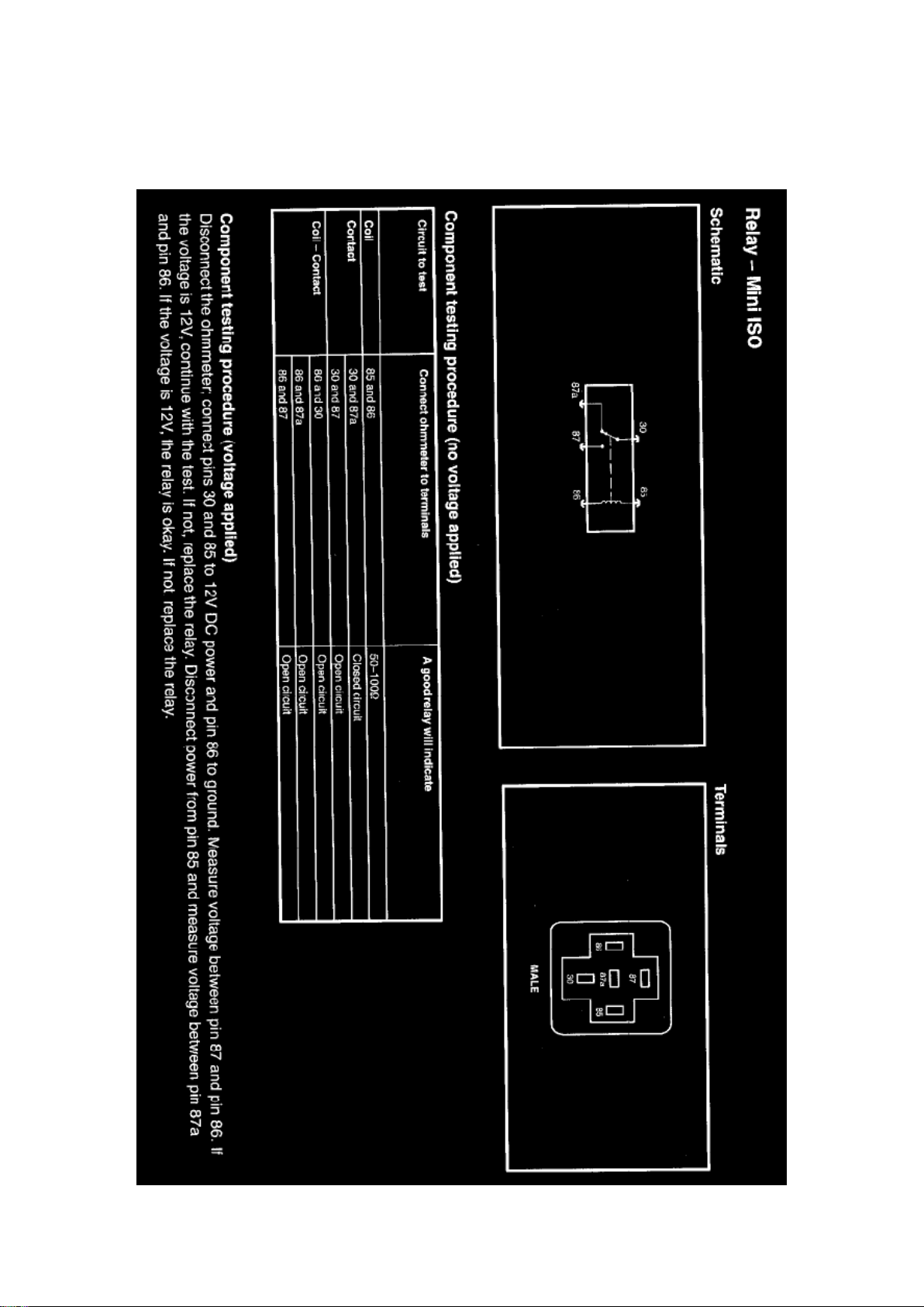
Ford Explorer Sport Trac 4wd Workshop Manual (V8-4.6L VIN 8 (2007))
Ford Workshop Manuals > Relays and Modules > Relays and Modules - HVAC > Blower Motor Relay > Component
Information > Testing and Inspection > Blower Motor Relay 1
Page 44

Page 45
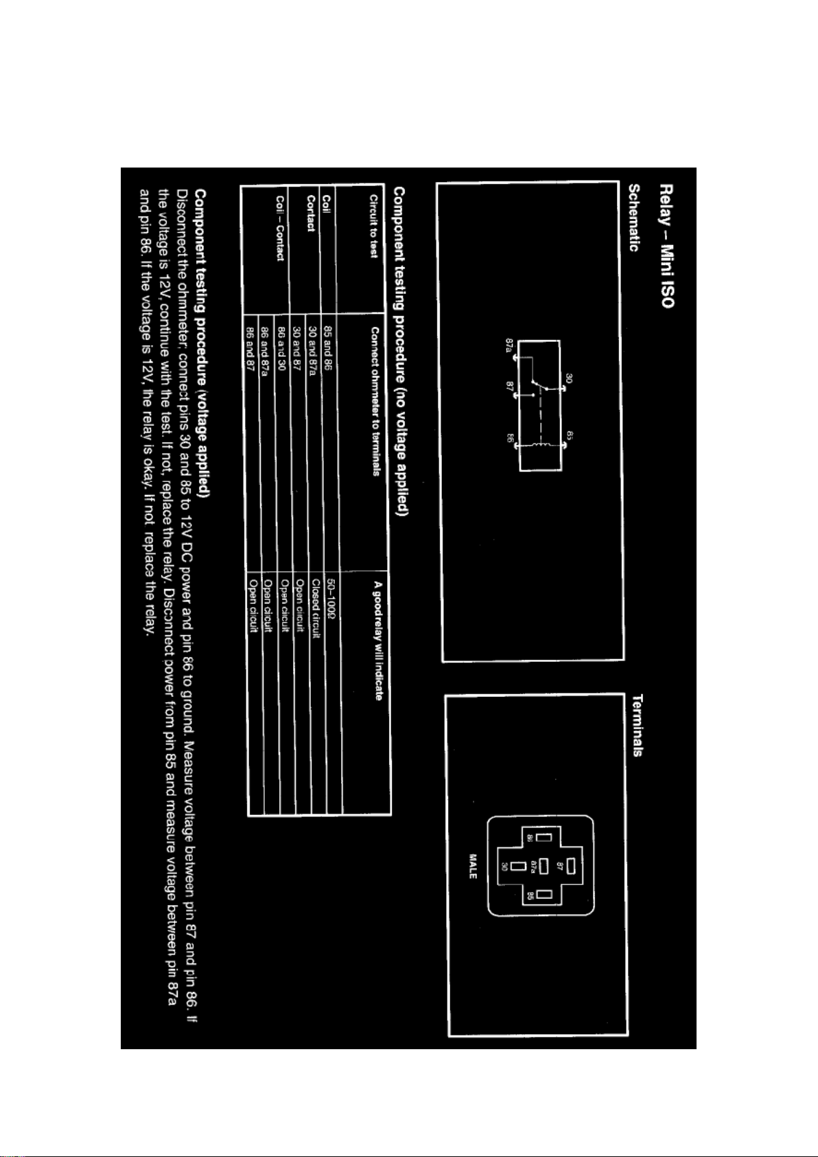
Ford Explorer Sport Trac 4wd Workshop Manual (V8-4.6L VIN 8 (2007))
Ford Workshop Manuals > Relays and Modules > Relays and Modules - HVAC > Blower Motor Relay > Component
Information > Testing and Inspection > Blower Motor Relay 1 > Page 67
Page 46

Page 47
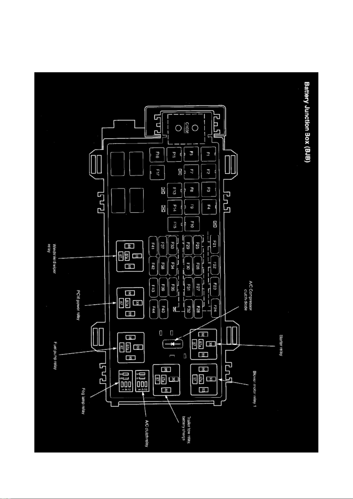
Ford Explorer Sport Trac 4wd Workshop Manual (V8-4.6L VIN 8 (2007))
Ford Workshop Manuals > Relays and Modules > Relays and Modules - HVAC > Compressor Clutch Relay > Component
Information > Locations
Page 48

Page 49

Ford Explorer Sport Trac 4wd Workshop Manual (V8-4.6L VIN 8 (2007))
Ford Workshop Manuals > Relays and Modules > Relays and Modules - HVAC > Compressor Clutch Relay > Component
Information > Locations > Page 71
Page 50

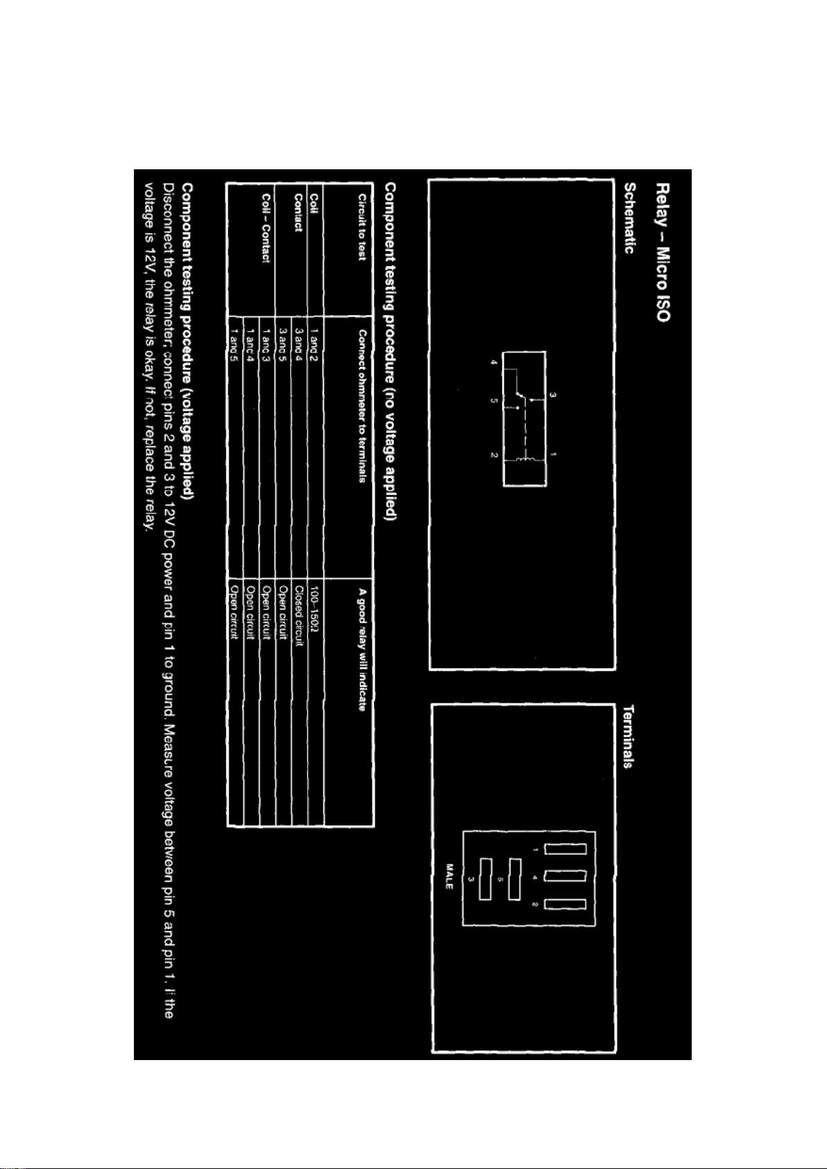
Compressor Clutch Relay: Description and Operation
AIR CONDITIONING (A/C) CLUTCH RELAY (A/CCR)
NOTE: The PCM PIDs WAC and wide open throttle air conditioning cutoff fault (WACF) are used to
monitor the A/CCR output.
The A/CCR is wired normally open. There is no direct electrical connection between the A/C switch
or electronic automatic temperature control (EATC) module and the A/C clutch. The PCM receives
a signal indicating that A/C is requested. For some applications, this message is sent through the
communications network. When A/C is requested, the PCM checks other A/C related inputs that
are available, such as A/C pressure switch and A/C cycling switch. If these inputs indicate A/C
operation is OK, and the engine conditions are OK (coolant temperature, engine RPM, throttle
position), the PCM grounds the A/CCR output, closing the relay contacts and sending voltage to
the A/CCR.
Page 51
Ford Explorer Sport Trac 4wd Workshop Manual (V8-4.6L VIN 8 (2007))
Ford Workshop Manuals > Relays and Modules > Relays and Modules - HVAC > Compressor Clutch Relay > Component
Information > Locations > Page 72
Page 52

Page 53
Ford Explorer Sport Trac 4wd Workshop Manual (V8-4.6L VIN 8 (2007))
Ford Workshop Manuals > Relays and Modules > Relays and Modules - HVAC > Control Module HVAC > Component
Information > Locations
Page 54

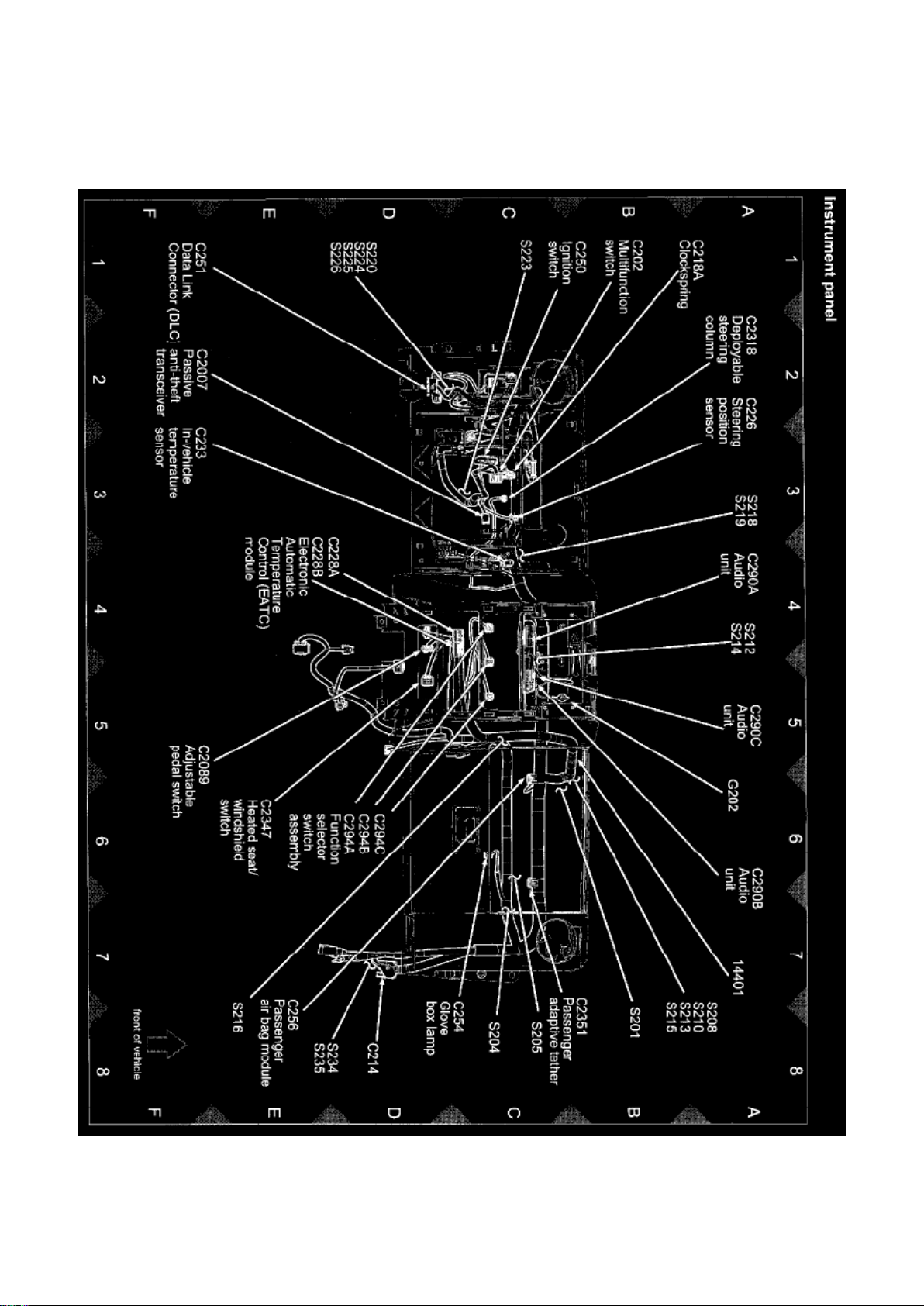
View 151-13 (Instrument Panel)
Page 55
Ford Explorer Sport Trac 4wd Workshop Manual (V8-4.6L VIN 8 (2007))
Ford Workshop Manuals > Relays and Modules > Relays and Modules - HVAC > Control Module HVAC > Component
Information > Locations > Page 76
Page 56

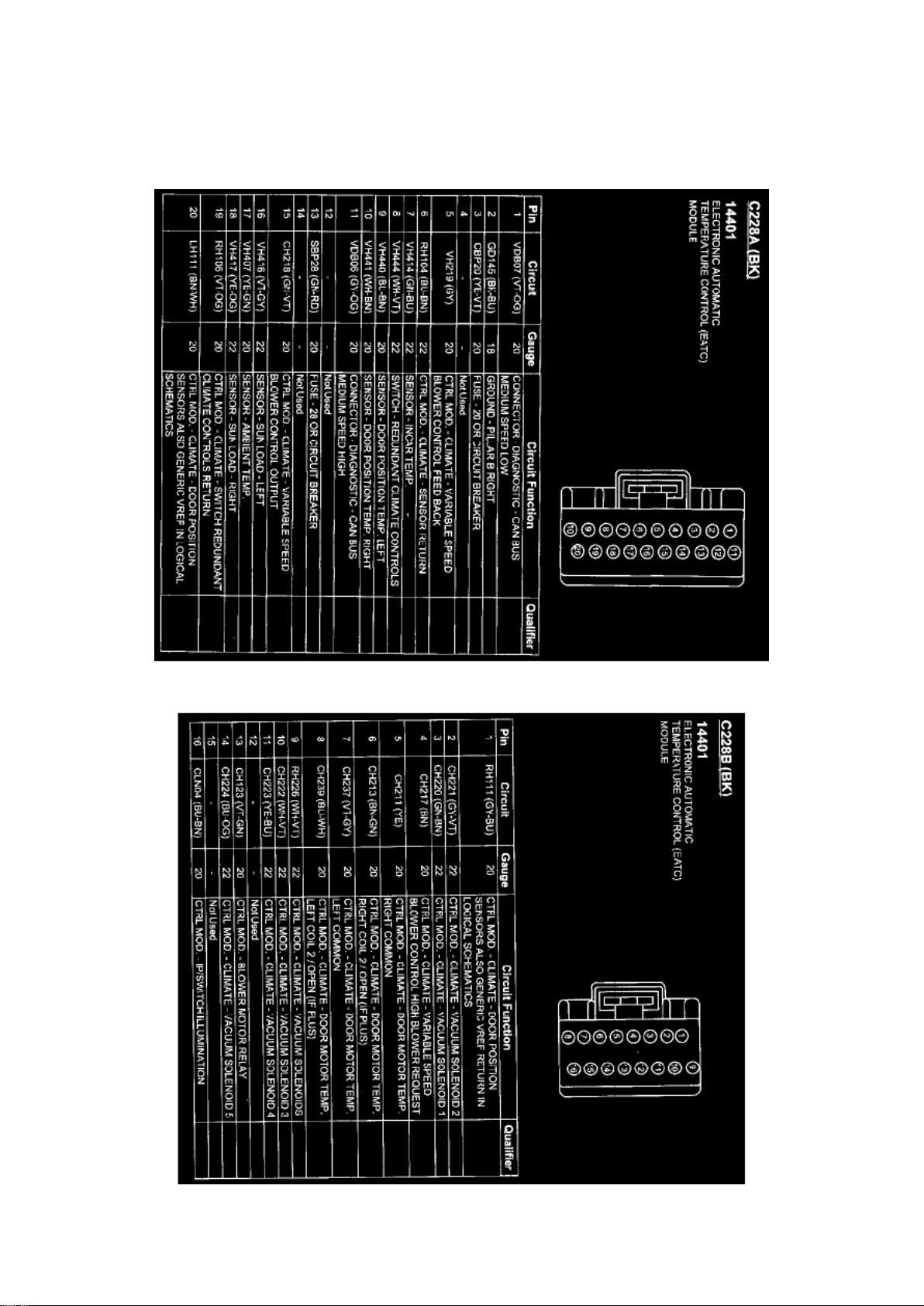
Control Module HVAC: Diagrams
C228A
C228B
Page 57

Ford Explorer Sport Trac 4wd Workshop Manual (V8-4.6L VIN 8 (2007))
Ford Workshop Manuals > Relays and Modules > Relays and Modules - Instrument Panel > Fuel Distance/Mileage Module
> Component Information > Technical Service Bulletins > Customer Interest for Fuel Distance/Mileage Module: > 09-21-7 >
Nov > 09 > Instruments - Trip Odometers/Fuel Economy Resets
Page 58

Fuel Distance/Mileage Module: Customer Interest Instruments - Trip Odometers/Fuel Economy
Resets
Page 59

TSB 09-21-7
11/02/09
TRIP A/TRIP B ODOMETER AND/OR AVERAGE FUEL ECONOMY RESETS
UNINTENTIONALLY
FORD: 2006-2010 Explorer 2007-2010 Explorer Sport Trac
MERCURY: 2006-2010 Mountaineer
ISSUE Some 2006-2010 Explorer, Mountaineer and 2007-2010 Explorer Sport Trac vehicles may
exhibit the trip odometer (Trip A or Trip B) or the Average Fuel Economy resetting unintentionally.
This condition may occur if there is an intermittent electrical connection on the power feed to the
cluster or if the reset button on the 3-button message center assembly is momentarily touched.
ACTION Follow the Service Procedure steps to correct the condition.
SERVICE PROCEDURE
1. With the key in the On position, display the trip odometer mileage.
2. Start the vehicle.
3. Cycle the key back Off and restart the vehicle.
4. Verify whether the trip mileage reset or not.
5. If not, proceed to Step 10.
6. If it reset, turn the key Off and remove the key from the ignition.
7. Activate the emergency flashers.
8. If the flashers do not function in the cluster (exterior lights perform as expected), perform normal
fuse and wiring diagnostics to correct the power
feed circuit.
9. Verify repair and proceed to Step 10.
10. Reprogram the Instrument Cluster Module (ICM) to the latest calibration using IDS release
63.07 and higher. This new calibration is not included
in the VCM 2009.9 DVD. Calibration files may also be obtained at the website.
NOTE
REPLACING THE CLUSTER OR THE 3-BUTTON MESSAGE CENTER ASSEMBLY WILL NOT
RESOLVE THIS ISSUE.
WARRANTY STATUS: Eligible Under Provisions Of New Vehicle Limited Warranty Coverage
IMPORTANT: Warranty coverage limits/policies are not altered by a TSB. Warranty coverage limits
are determined by the identified causal part.
OPERATION DESCRIPTION TIME
092107A 2006-2010 Explorer, 0.3 Hr.
Mountaineer 2007-2010 Explorer Sport Trac: Reprogram The ICM, Includes Time To Verify If The
Trip Odometer Reset (For Additional Repairs Use SLTS Operations If Available; Claim Additional
Page 60

Ford Explorer Sport Trac 4wd Workshop Manual (V8-4.6L VIN 8 (2007))
Ford Workshop Manuals > Relays and Modules > Relays and Modules - Instrument Panel > Fuel Distance/Mileage Module
> Component Information > Technical Service Bulletins > Customer Interest for Fuel Distance/Mileage Module: > 09-21-7 >
Nov > 09 > Instruments - Trip Odometers/Fuel Economy Resets > Page 86
Diagnosis Or Labor Performed As Actual Time)
DEALER CODING
CONDITION
BASIC PART NO. CODE
10849 04
Disclaimer
Page 61

Ford Explorer Sport Trac 4wd Workshop Manual (V8-4.6L VIN 8 (2007))
Ford Workshop Manuals > Relays and Modules > Relays and Modules - Instrument Panel > Fuel Distance/Mileage Module
> Component Information > Technical Service Bulletins > All Technical Service Bulletins for Fuel Distance/Mileage Module:
> 09-21-7 > Nov > 09 > Instruments - Trip Odometers/Fuel Economy Resets
Page 62

Fuel Distance/Mileage Module: All Technical Service Bulletins Instruments - Trip Odometers/Fuel
Economy Resets
Page 63

TSB 09-21-7
11/02/09
TRIP A/TRIP B ODOMETER AND/OR AVERAGE FUEL ECONOMY RESETS
UNINTENTIONALLY
FORD: 2006-2010 Explorer 2007-2010 Explorer Sport Trac
MERCURY: 2006-2010 Mountaineer
ISSUE Some 2006-2010 Explorer, Mountaineer and 2007-2010 Explorer Sport Trac vehicles may
exhibit the trip odometer (Trip A or Trip B) or the Average Fuel Economy resetting unintentionally.
This condition may occur if there is an intermittent electrical connection on the power feed to the
cluster or if the reset button on the 3-button message center assembly is momentarily touched.
ACTION Follow the Service Procedure steps to correct the condition.
SERVICE PROCEDURE
1. With the key in the On position, display the trip odometer mileage.
2. Start the vehicle.
3. Cycle the key back Off and restart the vehicle.
4. Verify whether the trip mileage reset or not.
5. If not, proceed to Step 10.
6. If it reset, turn the key Off and remove the key from the ignition.
7. Activate the emergency flashers.
8. If the flashers do not function in the cluster (exterior lights perform as expected), perform normal
fuse and wiring diagnostics to correct the power
feed circuit.
9. Verify repair and proceed to Step 10.
10. Reprogram the Instrument Cluster Module (ICM) to the latest calibration using IDS release
63.07 and higher. This new calibration is not included
in the VCM 2009.9 DVD. Calibration files may also be obtained at the website.
NOTE
REPLACING THE CLUSTER OR THE 3-BUTTON MESSAGE CENTER ASSEMBLY WILL NOT
RESOLVE THIS ISSUE.
WARRANTY STATUS: Eligible Under Provisions Of New Vehicle Limited Warranty Coverage
IMPORTANT: Warranty coverage limits/policies are not altered by a TSB. Warranty coverage limits
are determined by the identified causal part.
OPERATION DESCRIPTION TIME
092107A 2006-2010 Explorer, 0.3 Hr.
Mountaineer 2007-2010 Explorer Sport Trac: Reprogram The ICM, Includes Time To Verify If The
Trip Odometer Reset (For Additional Repairs Use SLTS Operations If Available; Claim Additional
Page 64

Ford Explorer Sport Trac 4wd Workshop Manual (V8-4.6L VIN 8 (2007))
Ford Workshop Manuals > Relays and Modules > Relays and Modules - Instrument Panel > Fuel Distance/Mileage Module
> Component Information > Technical Service Bulletins > All Technical Service Bulletins for Fuel Distance/Mileage Module:
> 09-21-7 > Nov > 09 > Instruments - Trip Odometers/Fuel Economy Resets > Page 92
Diagnosis Or Labor Performed As Actual Time)
DEALER CODING
CONDITION
BASIC PART NO. CODE
10849 04
Disclaimer
Page 65

Ford Explorer Sport Trac 4wd Workshop Manual (V8-4.6L VIN 8 (2007))
Ford Workshop Manuals > Relays and Modules > Relays and Modules - Instrument Panel > Instrument Panel Control
Module > Component Information > Technical Service Bulletins > Customer Interest for Instrument Panel Control Module: >
09-21-7 > Nov > 09 > Instruments - Trip Odometers/Fuel Economy Resets
Page 66

Instrument Panel Control Module: Customer Interest Instruments - Trip Odometers/Fuel Economy
Resets
Page 67

TSB 09-21-7
11/02/09
TRIP A/TRIP B ODOMETER AND/OR AVERAGE FUEL ECONOMY RESETS
UNINTENTIONALLY
FORD: 2006-2010 Explorer 2007-2010 Explorer Sport Trac
MERCURY: 2006-2010 Mountaineer
ISSUE Some 2006-2010 Explorer, Mountaineer and 2007-2010 Explorer Sport Trac vehicles may
exhibit the trip odometer (Trip A or Trip B) or the Average Fuel Economy resetting unintentionally.
This condition may occur if there is an intermittent electrical connection on the power feed to the
cluster or if the reset button on the 3-button message center assembly is momentarily touched.
ACTION Follow the Service Procedure steps to correct the condition.
SERVICE PROCEDURE
1. With the key in the On position, display the trip odometer mileage.
2. Start the vehicle.
3. Cycle the key back Off and restart the vehicle.
4. Verify whether the trip mileage reset or not.
5. If not, proceed to Step 10.
6. If it reset, turn the key Off and remove the key from the ignition.
7. Activate the emergency flashers.
8. If the flashers do not function in the cluster (exterior lights perform as expected), perform normal
fuse and wiring diagnostics to correct the power
feed circuit.
9. Verify repair and proceed to Step 10.
10. Reprogram the Instrument Cluster Module (ICM) to the latest calibration using IDS release
63.07 and higher. This new calibration is not included
in the VCM 2009.9 DVD. Calibration files may also be obtained at the website.
NOTE
REPLACING THE CLUSTER OR THE 3-BUTTON MESSAGE CENTER ASSEMBLY WILL NOT
RESOLVE THIS ISSUE.
WARRANTY STATUS: Eligible Under Provisions Of New Vehicle Limited Warranty Coverage
IMPORTANT: Warranty coverage limits/policies are not altered by a TSB. Warranty coverage limits
are determined by the identified causal part.
OPERATION DESCRIPTION TIME
092107A 2006-2010 Explorer, 0.3 Hr.
Mountaineer 2007-2010 Explorer Sport Trac: Reprogram The ICM, Includes Time To Verify If The
Trip Odometer Reset (For Additional Repairs Use SLTS Operations If Available; Claim Additional
Page 68

Ford Explorer Sport Trac 4wd Workshop Manual (V8-4.6L VIN 8 (2007))
Ford Workshop Manuals > Relays and Modules > Relays and Modules - Instrument Panel > Instrument Panel Control
Module > Component Information > Technical Service Bulletins > Customer Interest for Instrument Panel Control Module: >
09-21-7 > Nov > 09 > Instruments - Trip Odometers/Fuel Economy Resets > Page 101
Diagnosis Or Labor Performed As Actual Time)
DEALER CODING
CONDITION
BASIC PART NO. CODE
10849 04
Disclaimer
Page 69

Ford Explorer Sport Trac 4wd Workshop Manual (V8-4.6L VIN 8 (2007))
Ford Workshop Manuals > Relays and Modules > Relays and Modules - Instrument Panel > Instrument Panel Control
Module > Component Information > Technical Service Bulletins > All Technical Service Bulletins for Instrument Panel
Control Module: > 09-21-7 > Nov > 09 > Instruments - Trip Odometers/Fuel Economy Resets
Page 70

Instrument Panel Control Module: All Technical Service Bulletins Instruments - Trip
Odometers/Fuel Economy Resets
Page 71

TSB 09-21-7
11/02/09
TRIP A/TRIP B ODOMETER AND/OR AVERAGE FUEL ECONOMY RESETS
UNINTENTIONALLY
FORD: 2006-2010 Explorer 2007-2010 Explorer Sport Trac
MERCURY: 2006-2010 Mountaineer
ISSUE Some 2006-2010 Explorer, Mountaineer and 2007-2010 Explorer Sport Trac vehicles may
exhibit the trip odometer (Trip A or Trip B) or the Average Fuel Economy resetting unintentionally.
This condition may occur if there is an intermittent electrical connection on the power feed to the
cluster or if the reset button on the 3-button message center assembly is momentarily touched.
ACTION Follow the Service Procedure steps to correct the condition.
SERVICE PROCEDURE
1. With the key in the On position, display the trip odometer mileage.
2. Start the vehicle.
3. Cycle the key back Off and restart the vehicle.
4. Verify whether the trip mileage reset or not.
5. If not, proceed to Step 10.
6. If it reset, turn the key Off and remove the key from the ignition.
7. Activate the emergency flashers.
8. If the flashers do not function in the cluster (exterior lights perform as expected), perform normal
fuse and wiring diagnostics to correct the power
feed circuit.
9. Verify repair and proceed to Step 10.
10. Reprogram the Instrument Cluster Module (ICM) to the latest calibration using IDS release
63.07 and higher. This new calibration is not included
in the VCM 2009.9 DVD. Calibration files may also be obtained at the website.
NOTE
REPLACING THE CLUSTER OR THE 3-BUTTON MESSAGE CENTER ASSEMBLY WILL NOT
RESOLVE THIS ISSUE.
WARRANTY STATUS: Eligible Under Provisions Of New Vehicle Limited Warranty Coverage
IMPORTANT: Warranty coverage limits/policies are not altered by a TSB. Warranty coverage limits
are determined by the identified causal part.
OPERATION DESCRIPTION TIME
092107A 2006-2010 Explorer, 0.3 Hr.
Mountaineer 2007-2010 Explorer Sport Trac: Reprogram The ICM, Includes Time To Verify If The
Trip Odometer Reset (For Additional Repairs Use SLTS Operations If Available; Claim Additional
Page 72

Ford Explorer Sport Trac 4wd Workshop Manual (V8-4.6L VIN 8 (2007))
Ford Workshop Manuals > Relays and Modules > Relays and Modules - Instrument Panel > Instrument Panel Control
Module > Component Information > Technical Service Bulletins > All Technical Service Bulletins for Instrument Panel
Control Module: > 09-21-7 > Nov > 09 > Instruments - Trip Odometers/Fuel Economy Resets > Page 107
Diagnosis Or Labor Performed As Actual Time)
DEALER CODING
CONDITION
BASIC PART NO. CODE
10849 04
Disclaimer
Page 73
Ford Explorer Sport Trac 4wd Workshop Manual (V8-4.6L VIN 8 (2007))
Ford Workshop Manuals > Relays and Modules > Relays and Modules - Lighting and Horns > Fog/Driving Lamp Relay >
Component Information > Locations
Page 74

Page 75
Ford Explorer Sport Trac 4wd Workshop Manual (V8-4.6L VIN 8 (2007))
Ford Workshop Manuals > Relays and Modules > Relays and Modules - Lighting and Horns > Fog/Driving Lamp Relay >
Component Information > Locations > Page 112
Page 76

Page 77
Ford Explorer Sport Trac 4wd Workshop Manual (V8-4.6L VIN 8 (2007))
Ford Workshop Manuals > Relays and Modules > Relays and Modules - Lighting and Horns > Parking Lamp Relay >
Component Information > Locations
Page 78
Ford Explorer Sport Trac 4wd Workshop Manual (V8-4.6L VIN 8 (2007))
Ford Workshop Manuals > Relays and Modules > Relays and Modules - Lighting and Horns > Parking Lamp Relay >
Component Information > Locations > Page 116
Page 79

Page 80
Ford Explorer Sport Trac 4wd Workshop Manual (V8-4.6L VIN 8 (2007))
Ford Workshop Manuals > Relays and Modules > Relays and Modules - Lighting and Horns > Trailer Lighting Relay >
Component Information > Locations
Page 81

Page 82
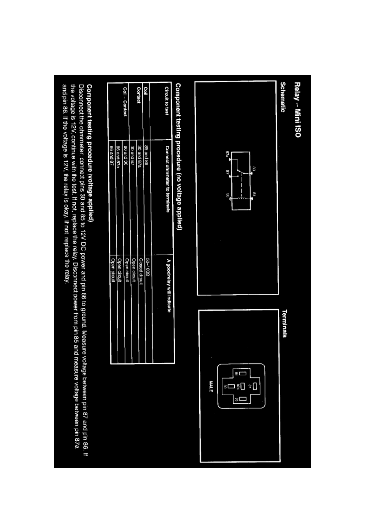
Ford Explorer Sport Trac 4wd Workshop Manual (V8-4.6L VIN 8 (2007))
Ford Workshop Manuals > Relays and Modules > Relays and Modules - Lighting and Horns > Trailer Lighting Relay >
Component Information > Locations > Page 120
Page 83

Page 84
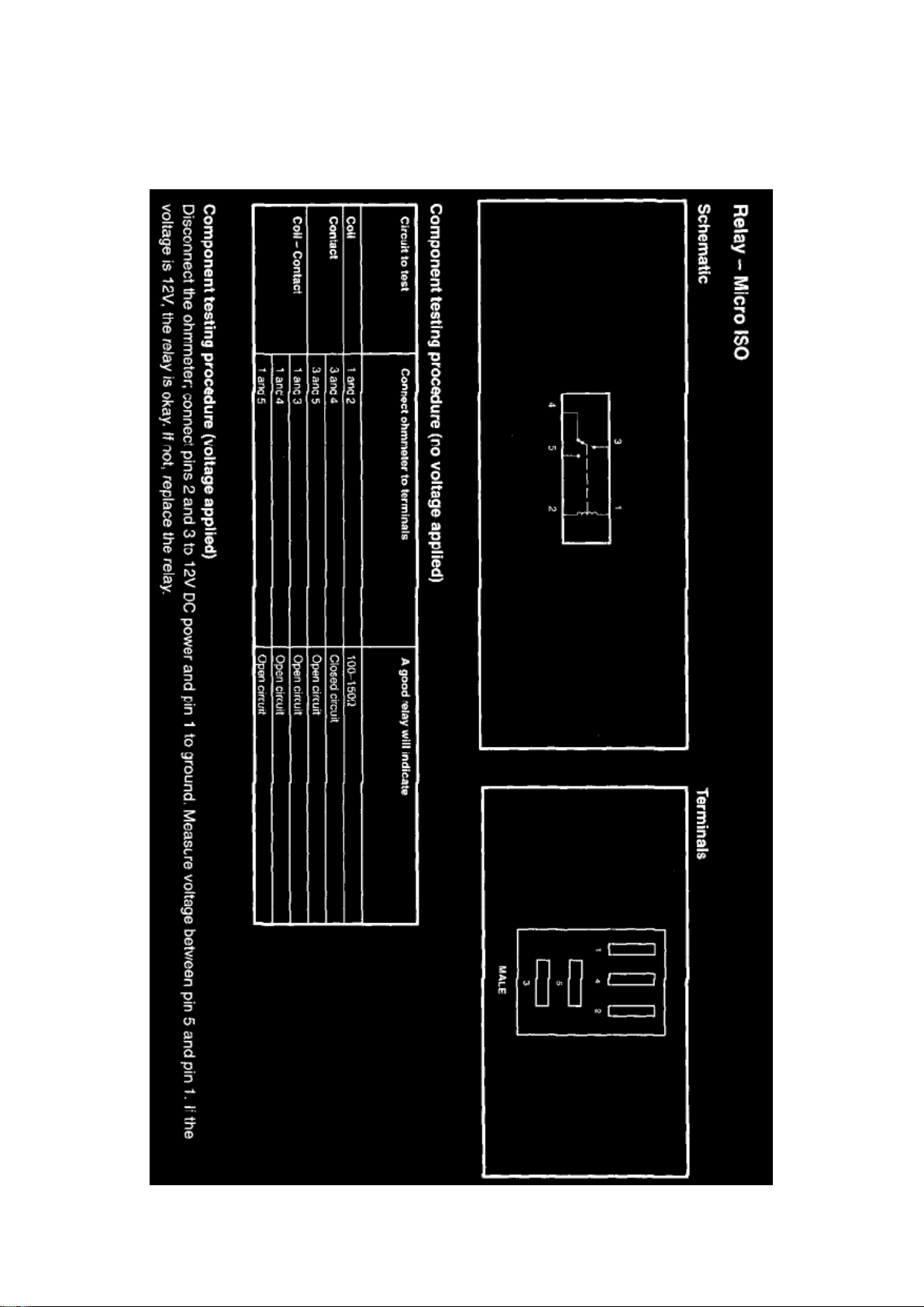
Ford Explorer Sport Trac 4wd Workshop Manual (V8-4.6L VIN 8 (2007))
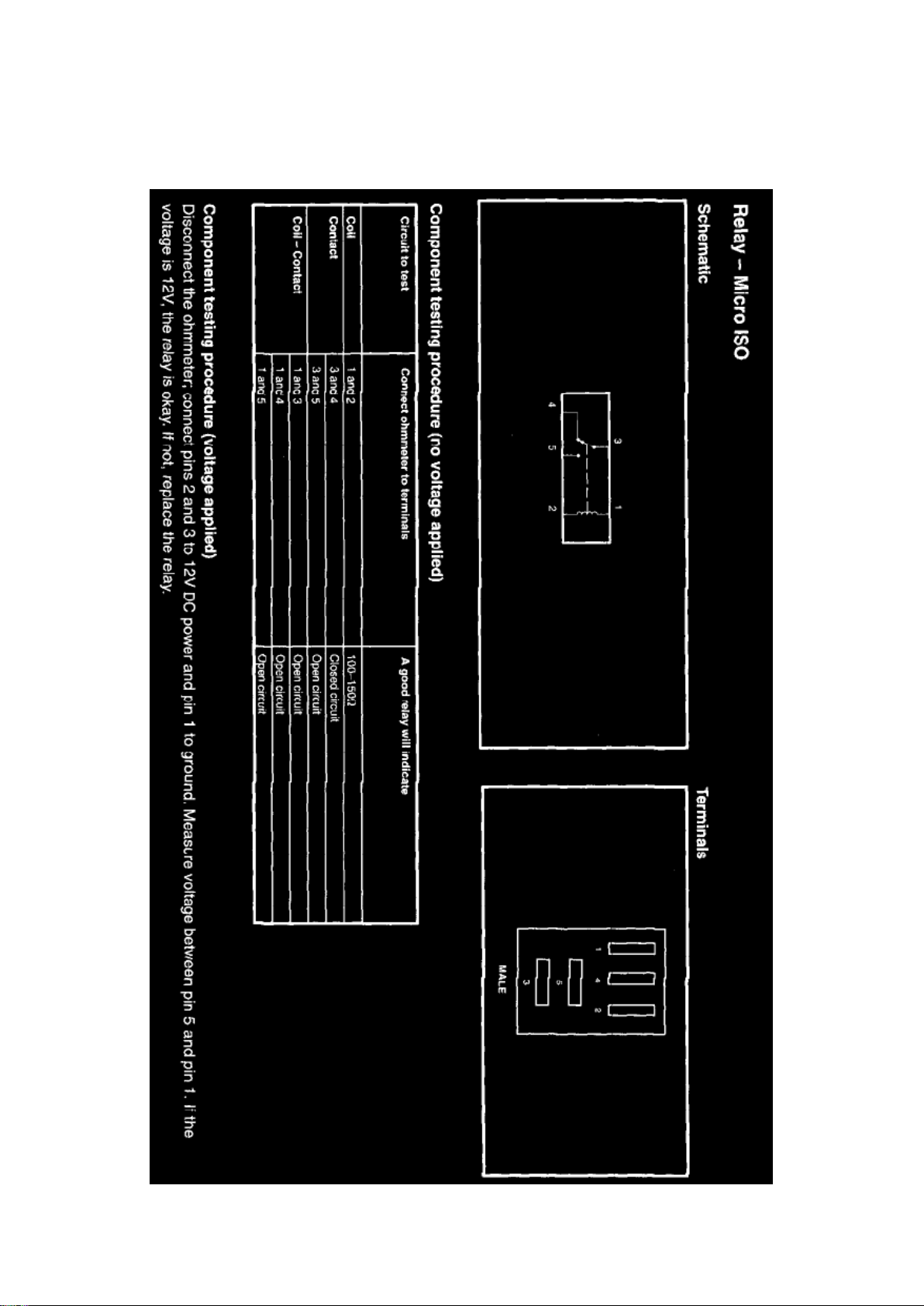
Ford Workshop Manuals > Relays and Modules > Relays and Modules - Power and Ground Distribution > Micro ISO Relay
> Component Information > Testing and Inspection
Page 85

Page 86
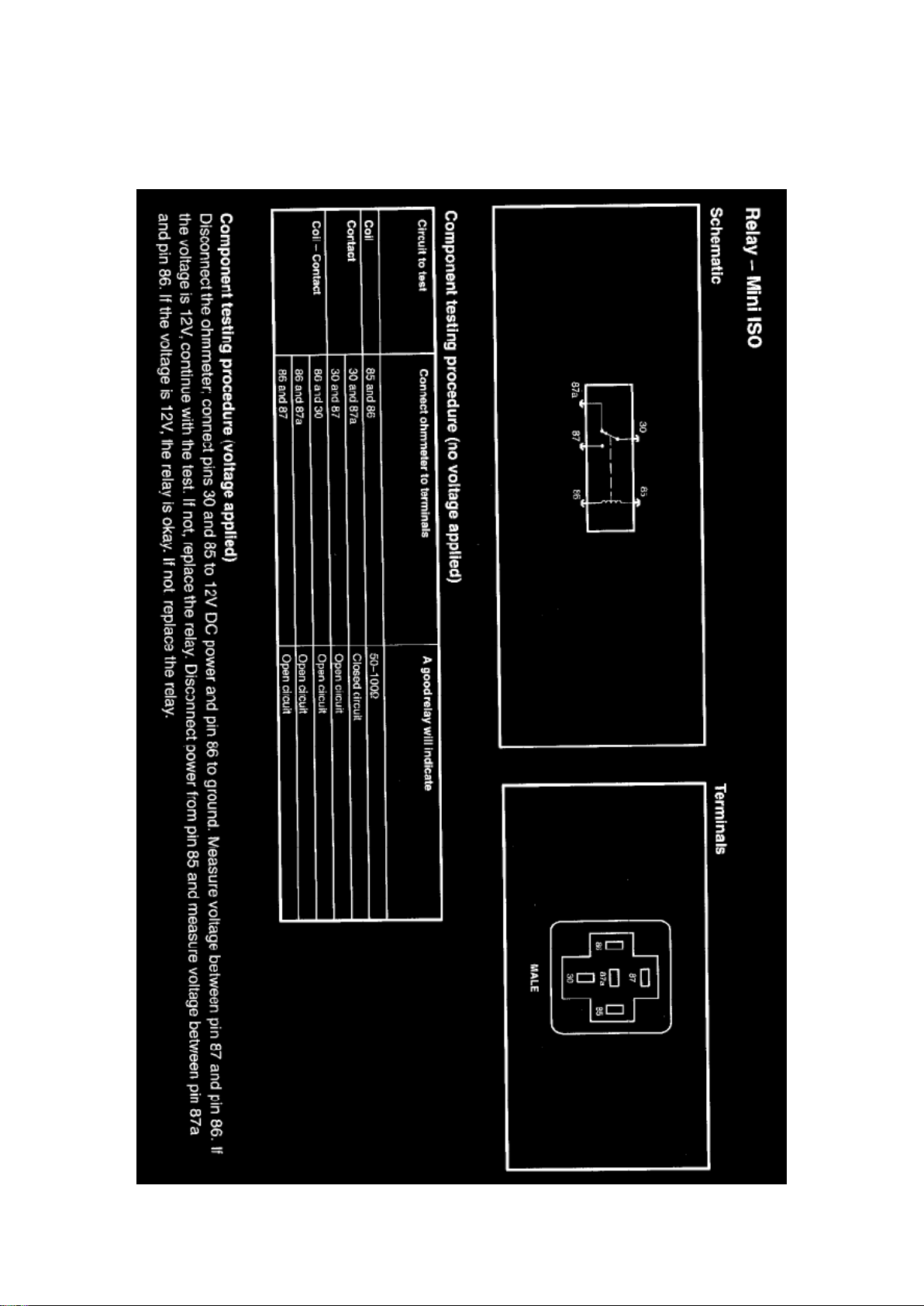
Ford Explorer Sport Trac 4wd Workshop Manual (V8-4.6L VIN 8 (2007))
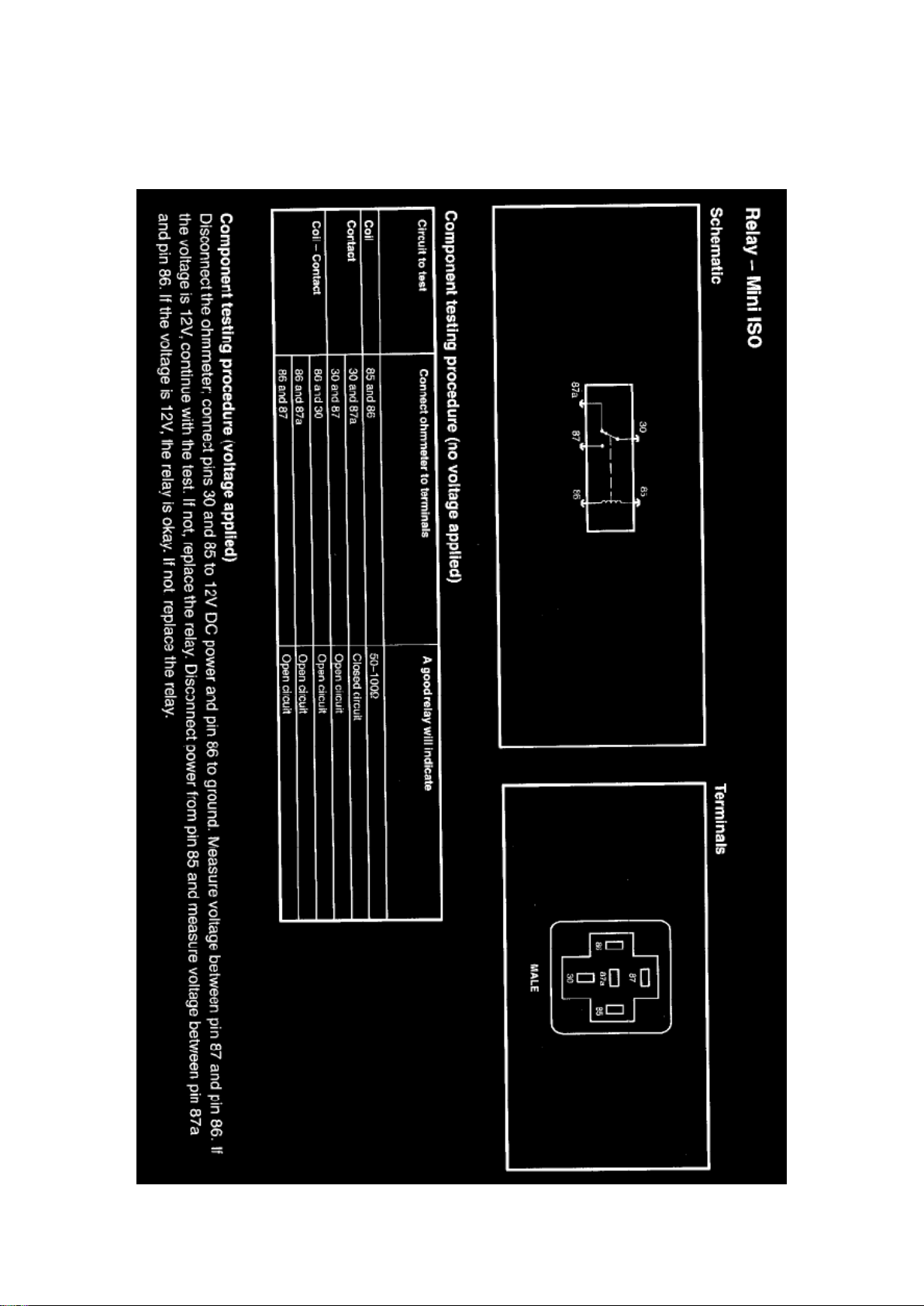
Ford Workshop Manuals > Relays and Modules > Relays and Modules - Power and Ground Distribution > Mini ISO Relay >
Component Information > Testing and Inspection
Page 87

Page 88
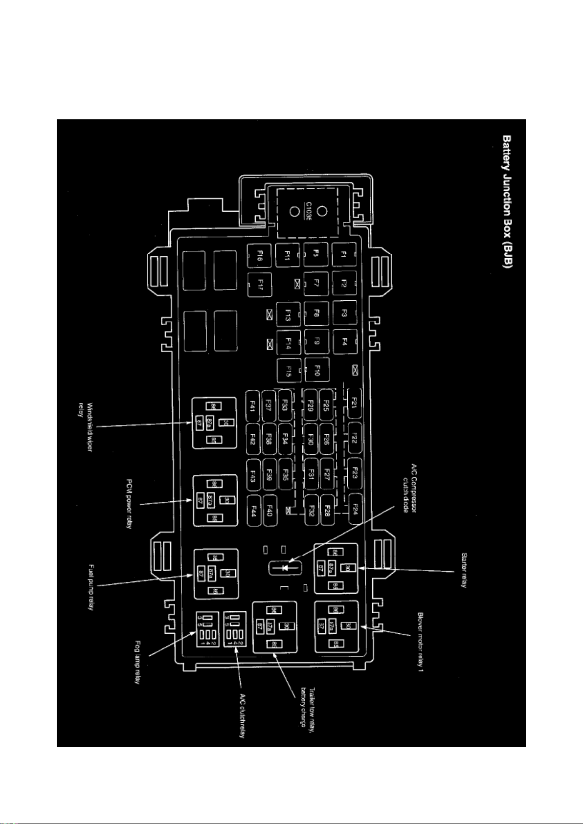
Ford Explorer Sport Trac 4wd Workshop Manual (V8-4.6L VIN 8 (2007))
Ford Workshop Manuals > Relays and Modules > Relays and Modules - Power and Ground Distribution > Power
Distribution Relay > Component Information > Locations
Page 89

Page 90
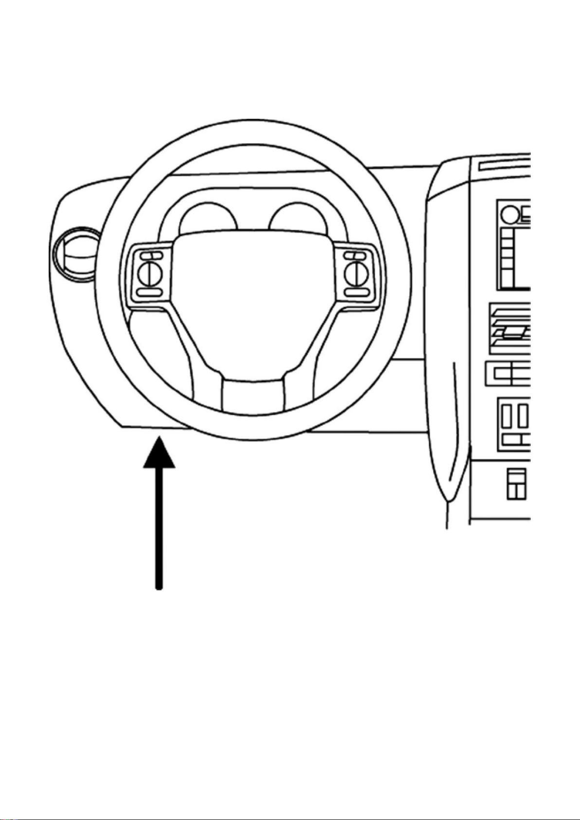
Ford Explorer Sport Trac 4wd Workshop Manual (V8-4.6L VIN 8 (2007))
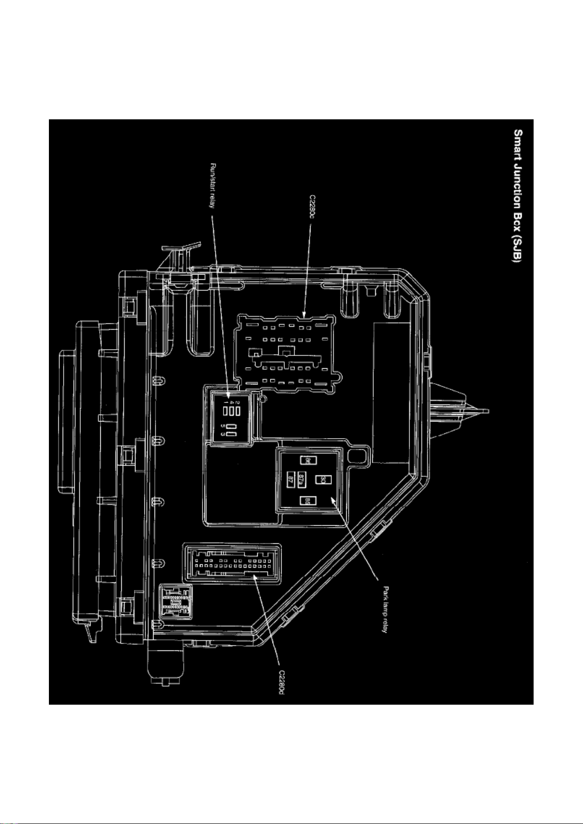
Ford Workshop Manuals > Relays and Modules > Relays and Modules - Power and Ground Distribution > Relay Box >
Component Information > Locations > Passenger Compartment Fuse Panel / Smart Junction Box (SJB)
Relay Box: Locations Passenger Compartment Fuse Panel / Smart Junction Box (SJB)
Location
Page 91
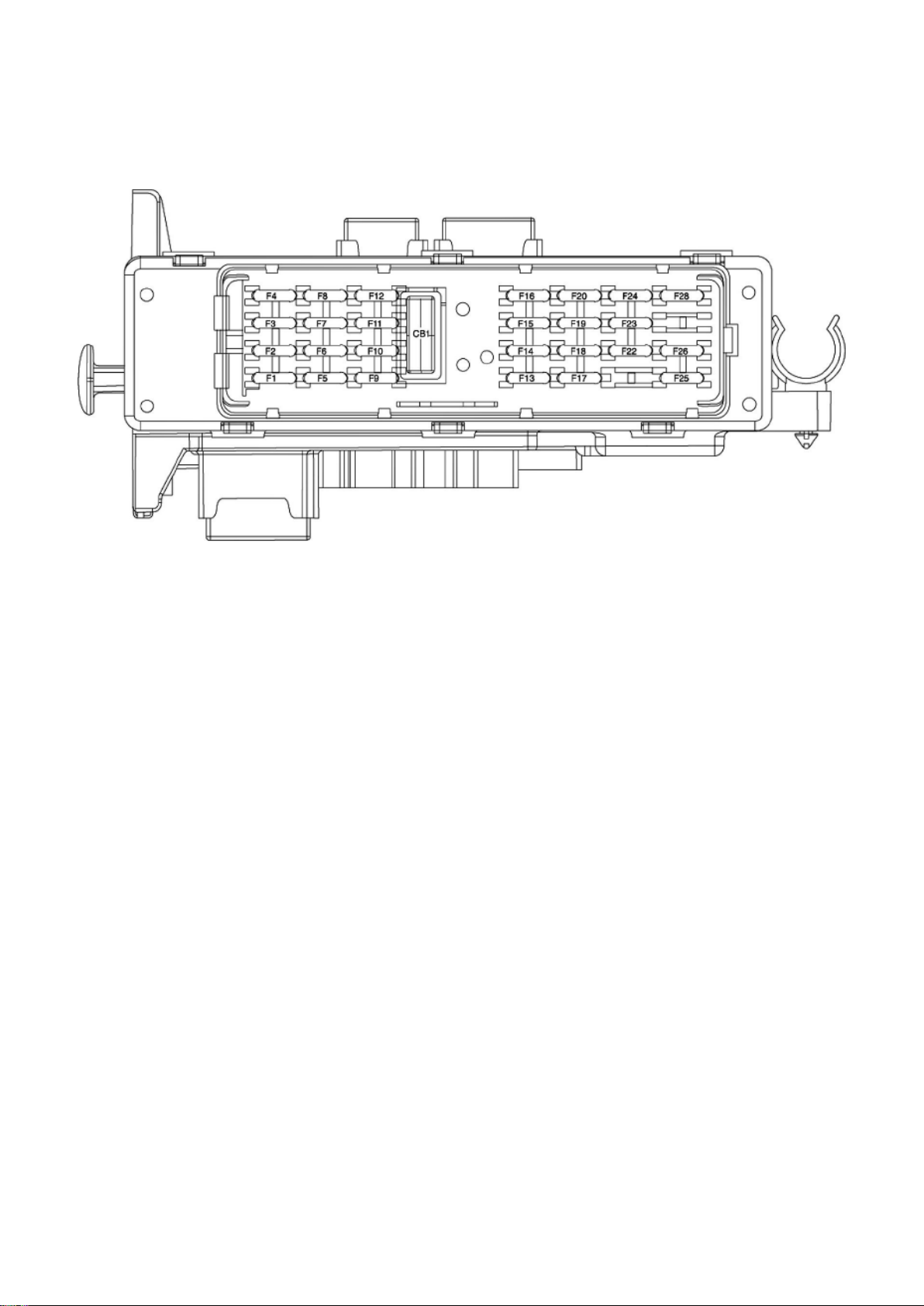
Ford Explorer Sport Trac 4wd Workshop Manual (V8-4.6L VIN 8 (2007))
Ford Workshop Manuals > Relays and Modules > Relays and Modules - Power and Ground Distribution > Relay Box >
Component Information > Locations > Passenger Compartment Fuse Panel / Smart Junction Box (SJB) > Page 135
Passenger Compartment Fuse Panel / Smart Junction Box (SJB)
Page 92
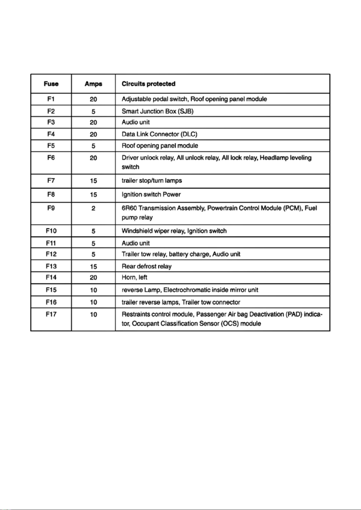
Ford Explorer Sport Trac 4wd Workshop Manual (V8-4.6L VIN 8 (2007))
Ford Workshop Manuals > Relays and Modules > Relays and Modules - Power and Ground Distribution > Relay Box >
Component Information > Locations > Passenger Compartment Fuse Panel / Smart Junction Box (SJB) > Page 136
Fuse
Page 93
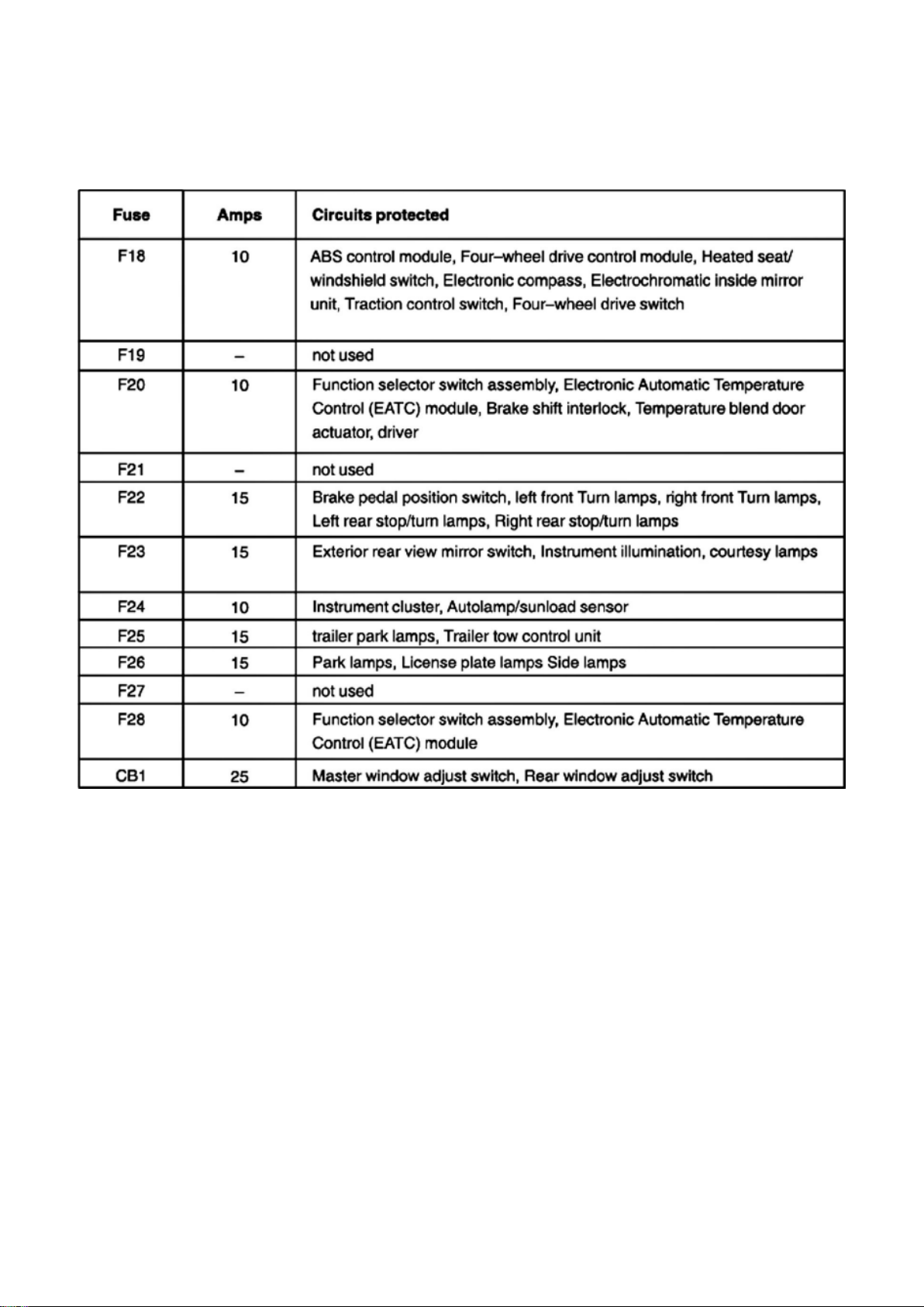
Ford Explorer Sport Trac 4wd Workshop Manual (V8-4.6L VIN 8 (2007))
Ford Workshop Manuals > Relays and Modules > Relays and Modules - Power and Ground Distribution > Relay Box >
Component Information > Locations > Passenger Compartment Fuse Panel / Smart Junction Box (SJB) > Page 137
Fuse
Page 94

Ford Explorer Sport Trac 4wd Workshop Manual (V8-4.6L VIN 8 (2007))
Ford Workshop Manuals > Relays and Modules > Relays and Modules - Power and Ground Distribution > Relay Box >
Component Information > Locations > Passenger Compartment Fuse Panel / Smart Junction Box (SJB) > Page 138
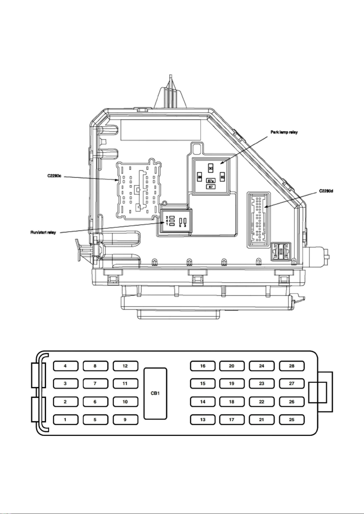
Passenger Compartment Fuse Panel / Smart Junction Box (SJB) Side View
Page 95
Ford Explorer Sport Trac 4wd Workshop Manual (V8-4.6L VIN 8 (2007))
Ford Workshop Manuals > Relays and Modules > Relays and Modules - Power and Ground Distribution > Relay Box >
Component Information > Locations > Passenger Compartment Fuse Panel / Smart Junction Box (SJB) > Page 139
Passenger Compartment Fuse Panel / Smart Junction Box (SJB) Side View
Page 96

Passenger Compartment Fuse Panel / Smart Junction Box (SJB)
Page 97
Ford Explorer Sport Trac 4wd Workshop Manual (V8-4.6L VIN 8 (2007))
Ford Workshop Manuals > Relays and Modules > Relays and Modules - Power and Ground Distribution > Relay Box >
Component Information > Locations > Passenger Compartment Fuse Panel / Smart Junction Box (SJB) > Page 140
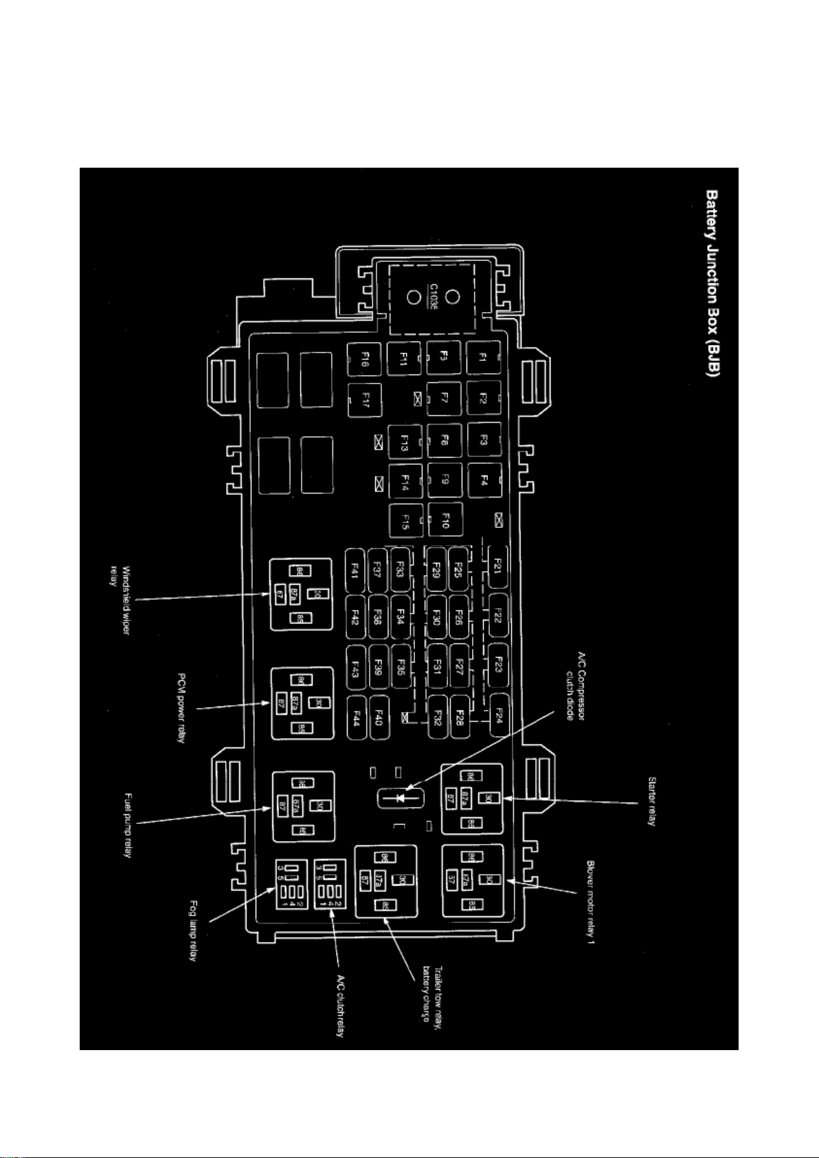
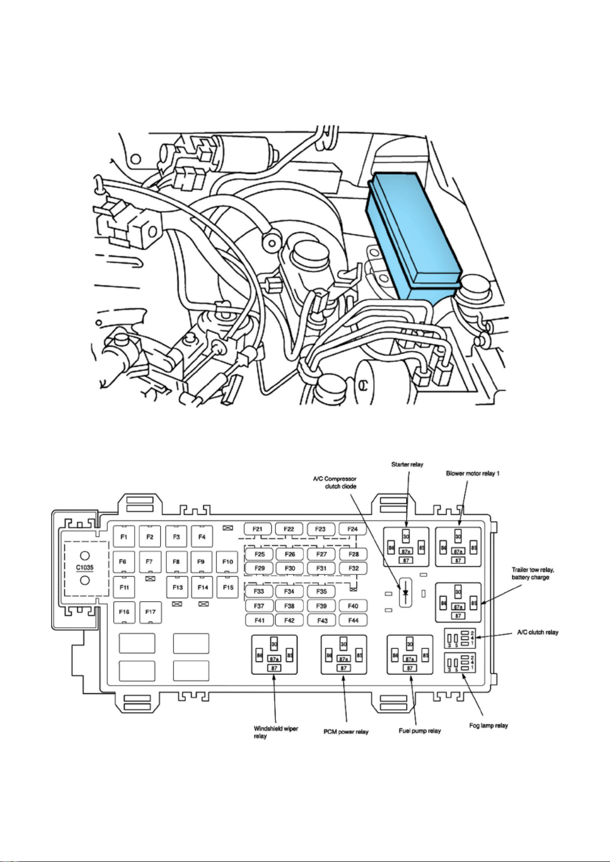
Relay Box: Locations Battery Junction Box (BJB) / Power Distribution Box
Page 98

Location
Battery Junction Box (BJB) / Power Distribution Box - Early Production
Page 99
Ford Explorer Sport Trac 4wd Workshop Manual (V8-4.6L VIN 8 (2007))
Ford Workshop Manuals > Relays and Modules > Relays and Modules - Power and Ground Distribution > Relay Box >
Component Information > Locations > Passenger Compartment Fuse Panel / Smart Junction Box (SJB) > Page 141
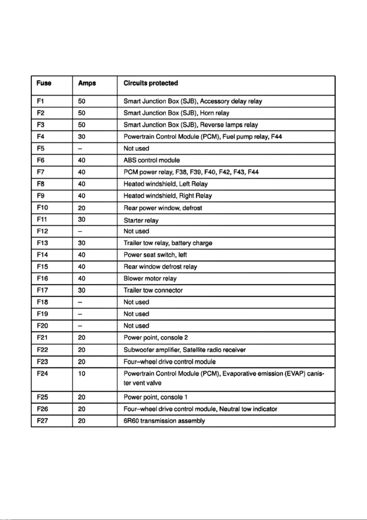
Fuse
Page 100
Ford Explorer Sport Trac 4wd Workshop Manual (V8-4.6L VIN 8 (2007))
Ford Workshop Manuals > Relays and Modules > Relays and Modules - Power and Ground Distribution > Relay Box >
Component Information > Locations > Passenger Compartment Fuse Panel / Smart Junction Box (SJB) > Page 142
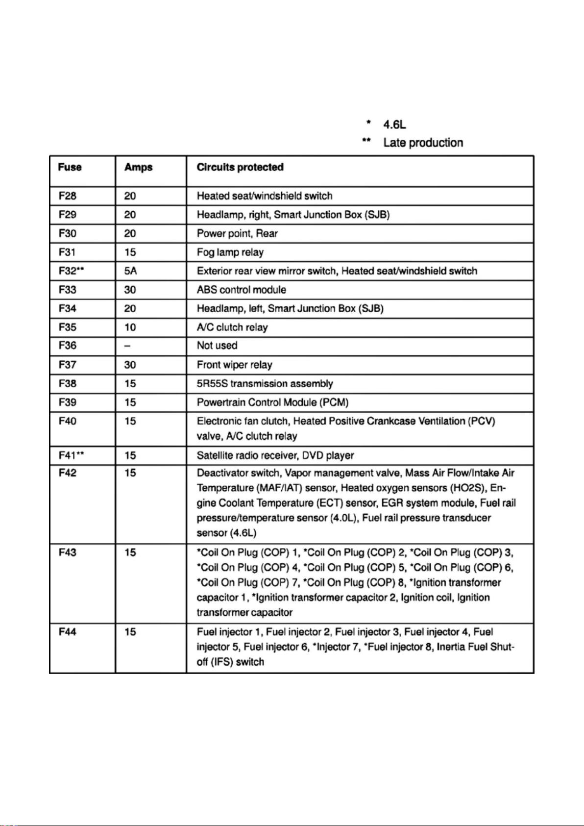
Fuse
 Loading...