

Page 1

Factory Workshop Manual
Ford
Explorer 2wd
V6-4.0L (2009)
Anonymous
1st January 2018
Make
Model
Engine and year
This manual was submitted by
Date
Page 2
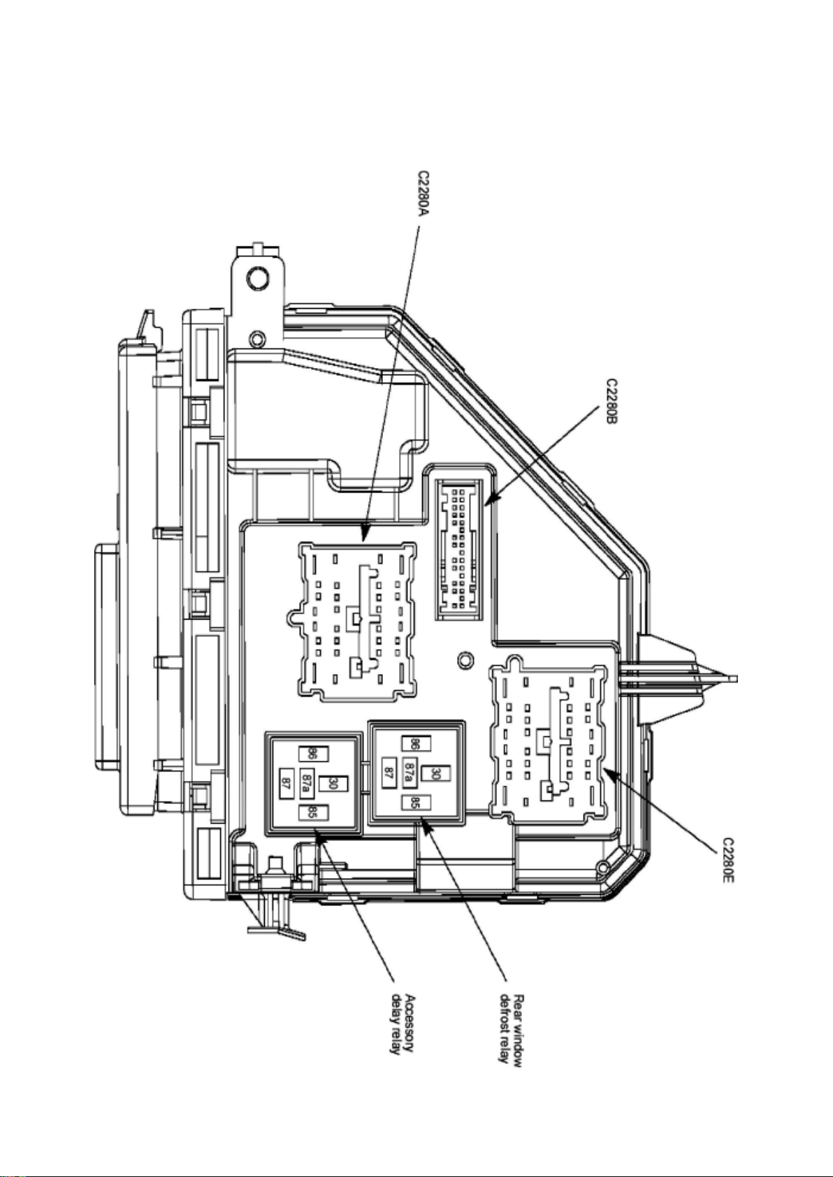
Ford Explorer 2wd Workshop Manual (V6-4.0L (2009))
Ford Workshop Manuals > Relays and Modules > Relays and Modules - Accessories and Optional Equipment > Accessory
Delay Module > Accessory Delay Relay > Component Information > Locations
Page 3

Page 4
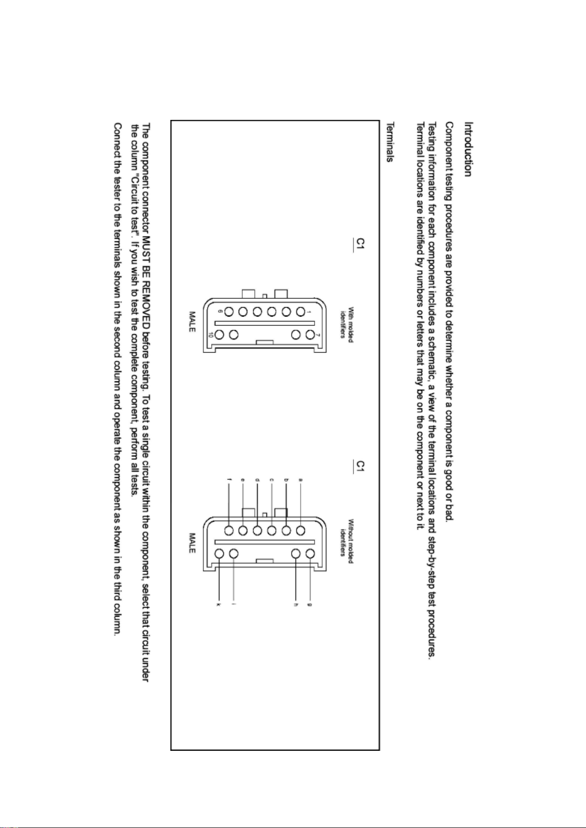
Ford Explorer 2wd Workshop Manual (V6-4.0L (2009))
Ford Workshop Manuals > Relays and Modules > Relays and Modules - Accessories and Optional Equipment > Accessory
Delay Module > Accessory Delay Relay > Component Information > Locations > Page 8
Page 5

Accessory Delay Relay: Testing and Inspection
Page 6
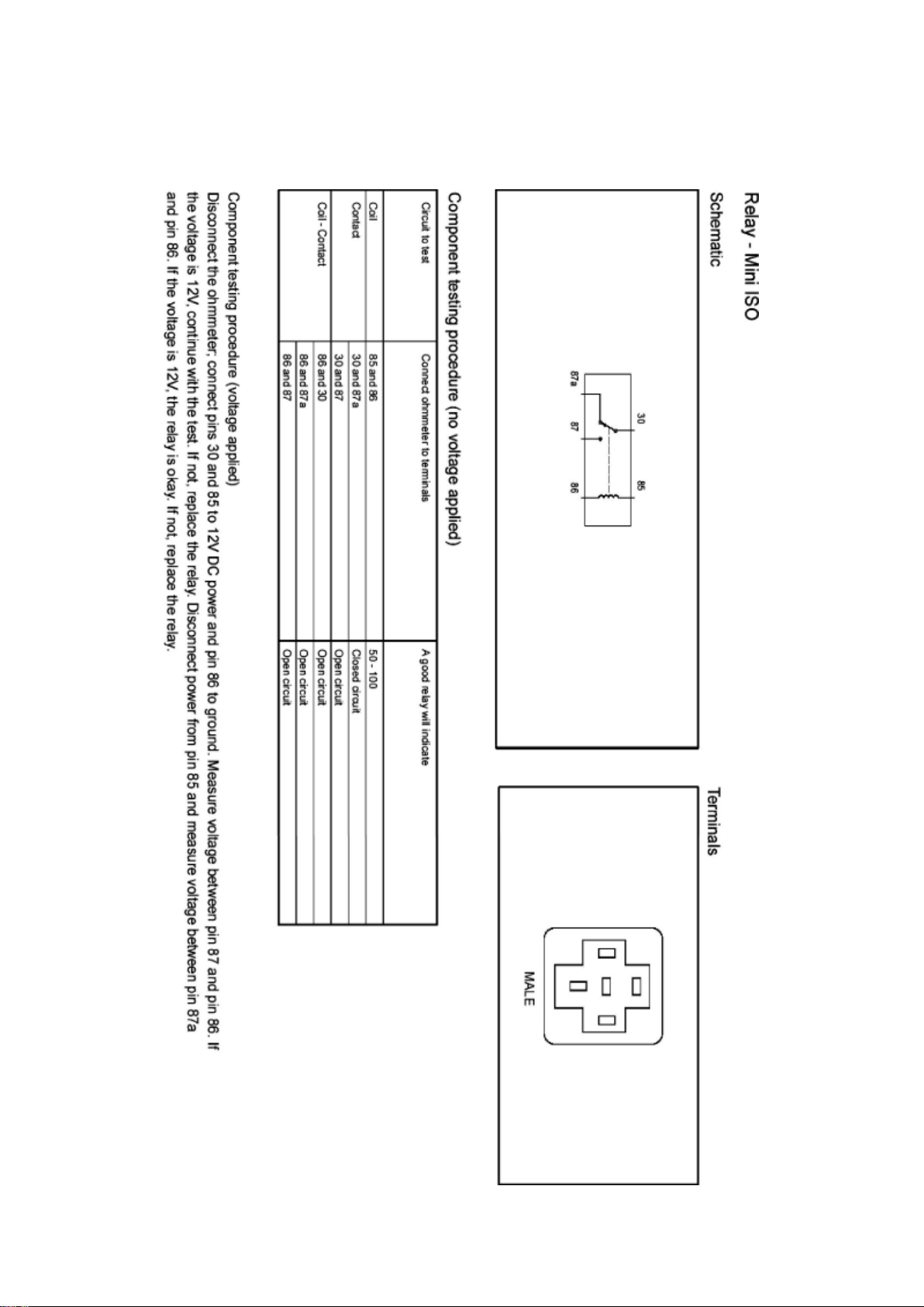
Ford Explorer 2wd Workshop Manual (V6-4.0L (2009))
Ford Workshop Manuals > Relays and Modules > Relays and Modules - Accessories and Optional Equipment > Accessory
Delay Module > Accessory Delay Relay > Component Information > Locations > Page 9
Page 7

Page 8

Ford Explorer 2wd Workshop Manual (V6-4.0L (2009))
Ford Workshop Manuals > Relays and Modules > Relays and Modules - Accessories and Optional Equipment >
Communications Control Module > Component Information > Technical Service Bulletins > Customer Interest for
Communications Control Module: > 10-2-8 > Feb > 10 > SYNC(R) System - Defaults To 'Privacy Mode'
Communications Control Module: Customer Interest SYNC(R) System - Defaults To 'Privacy Mode'
TSB 10-2-8
02/15/10
SYNC SYSTEM DEFAULTS TO OR STAYS IN PRIVACY MODE, MULTIPLE VEHICLE LINES
FORD: 2008-2009 Taurus X 2008-2010 Focus, Fusion, Mustang, Taurus, Edge, Escape,
Expedition, Explorer Sport Trac, Explorer, F-150, F-250, F-350, F-450 2009-2010 Flex
LINCOLN: 2008-2010 MKZ 2009-2010 MKS 2008 Mark LT 2008-2010 MKX, Navigator 2010 MKT
MERCURY: 2008-2009 Sable 2008-2010 Milan, Mariner, Mountaineer
ISSUE Some customers of 2008-2010 SYNC-equipped vehicles may express concern with their
SYNC paired device defaulting, switching or staying on privacy mode. The customer may not be
able to accept the call through the SYNC system or must answer the call manually on their
personal device.
ACTION Follow the Service Procedure steps to correct the condition.
SERVICE PROCEDURE
1. Set the Privacy mode to Off on the device and recheck Sync operation.
2. If necessary, test the device on another vehicle with the same version SYNC. If the concern is
still present, the device is the concern. Continue with
normal WSM Diagnostics.
NOTE
PRIVACY MODE MEANS THAT THE PHONE IS CONTROLLING THE AUDIO. SYNC ONLY
MAKES REQUESTS TO THE PHONE TO TRANSFER THIS RESPONSIBILITY OR AUDIO TO
SYNC. IF THE PHONE DOES NOT ACCEPT THIS REQUEST OR THERE IS A PROBLEM IN
THE COMMUNICATION TO MAKE THIS HAPPEN, YOU ARE BY DEFAULT IN PRIVACY MODE.
WARRANTY STATUS: Information Only
Disclaimer
Page 9

Ford Explorer 2wd Workshop Manual (V6-4.0L (2009))
Ford Workshop Manuals > Relays and Modules > Relays and Modules - Accessories and Optional Equipment >
Communications Control Module > Component Information > Technical Service Bulletins > Customer Interest for
Communications Control Module: > 09-26-8 > Jan > 10 > SYNC(R) System - Software Update For Various Concerns
Page 10

Communications Control Module: Customer Interest SYNC(R) System - Software Update For
Various Concerns
Page 11

TSB 09-26-8
01/04/10
SYNC SOFTWARE UPDATE - VARIOUS ISSUES
FORD: 2008-2009 Focus, Fusion, Taurus X, Taurus, Edge, Explorer Sport Trac, Explorer 2009
Escape, Expedition, F-150, F-Super Duty, Flex
LINCOLN: 2008-2009 MKZ 2009 MKS 2008-2009 MKX, Navigator
MERCURY: 2008-2009 Milan, Sable, Mountaineer 2009 Mariner
This article supersedes TSB 9-22-14 to update the Service Procedure.
ISSUE Some 2008 and 2009 SYNC® equipped vehicles may exhibit one or more of the following
symptoms:
^ Universal Serial Bus (USB) port inoperative.
^ USB audio muting when using various non-Apple USB devices.
^ Phone book access difficulty on certain 2-digit phone book entries when using voice commands.
^ Excessive background noise and/or poor voice sound quality.
^ Phone book auto download inoperative on supported devices.
^ SYNC steering wheel control (SWC) switches being inoperative intermittently.
ACTION Follow the Service Procedure steps to correct the condition.
SERVICE PROCEDURE
Reprogram the accessory protocol inter[ace module (APIM) to the following consumer inter[ace
processor (CIP) software levels.
^ 9L3T-14D544-AE (vehicles not equipped with SYNC V2, 911 Assist and Vehicle Health Report)
^ 9L2T-14D544-BE (vehicles already equipped with SYNC V2, 911 Assist and Vehicle Health
Report)
Service Pack files may be obtained at www.syncmyride.com.
Reprogram the APIM
Contains software fix updates for the following:
^ Phone book auto download inoperative.
^ USB audio muting.
^ SYNC steering wheel control (SWC) switches being inoperative.
^ Voice recognition on 2-digit entries.
Page 12

Ford Explorer 2wd Workshop Manual (V6-4.0L (2009))
Ford Workshop Manuals > Relays and Modules > Relays and Modules - Accessories and Optional Equipment >
Communications Control Module > Component Information > Technical Service Bulletins > Customer Interest for
Communications Control Module: > 09-26-8 > Jan > 10 > SYNC(R) System - Software Update For Various Concerns >
Page 22
Page 13

^ USB port inoperative with diagnostic trouble code (DTC) B1342.
Page 14

^ Poor call sound quality.
This software update also contains enhancements that will improve the reliability of both Bluetooth
and USB connections to SYNC(R) from various consumer devices, and microphone enhancements
to reduce background noise, and will default Vehicle Health Report (if equipped) to off. The
Bluetooth enhancements improve the stability of hands-free calls, call waiting, caller ID, multiple
call handling and other mobile phone features. The USB enhancements improve support for media
players and the playing of file formats and podcasts.
NOTE
REFERENCE OTHER TECHNICAL SERVICE BULLETINS (TSB) FOR ADDITIONAL SYNC
SOFTWARE PROGRAMMING TIPS.
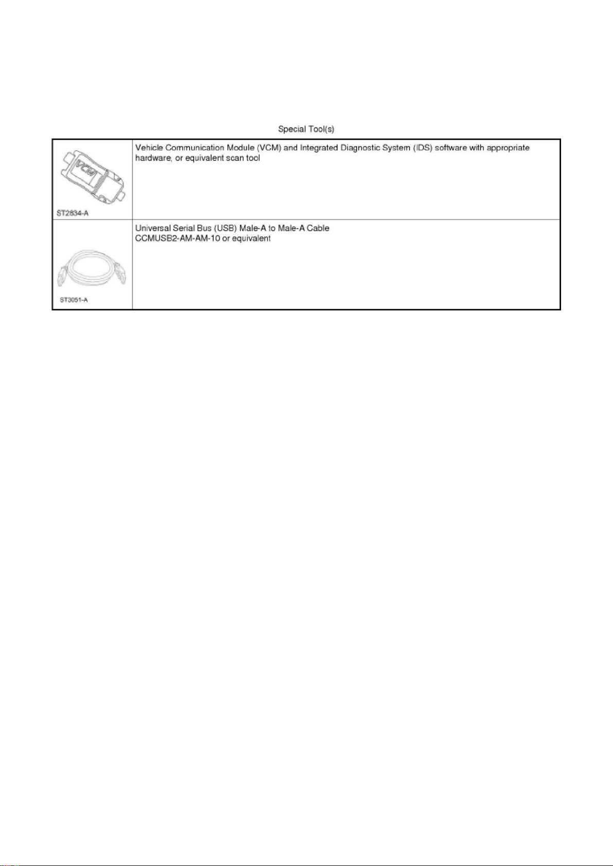
1. Connect the vehicle communication module (VCM) to the data link connector (DLC).
2. Connect the VCM to the Integrated Diagnostic System (IDS) tool or laptop running IDS software.
3. Turn the ignition key to the on position.
4. Launch IDS tool.
5. If required, update the VCM with the latest software.
6. Close the IDS tool.
7. From the PTS website, run OASIS by pressing the Read VIN & DTC's button. After vehicle
communication is established, press the GO button.
8. From the Vehicle Service Session screen, Select the SYNC button.
9. Press read APIM button.
10. Select software and press program APIM to update the SYNC module.
NOTE
YOU MUST USE A MALE-A TO MALE-A USB CABLE LIKE ROTUNDA PART NUMBER
CCMUSB2-AM-AM-10 TO COMPLETE THIS STEP.
NOTE
DO NOT DISCONNECT THE VCM OR USB CABLES DURING APIM PROGRAMMING.
NOTE
THE SYSTEM MAY PROMPT YOU TO INSTALL SOFTWARE FOR THE USB PORT. FOLLOW
THE ON SCREEN INSTRUCTIONS TO INSTALL THE USB PORT DRIVER ALREADY
INCLUDED IN WINDOWS XP.
11. Program both processors in the APIM (Vehicle Interface Processor (VIP) and CIP).
NOTE
DO NOT USE A MALE-TO-MALE USB DATA TRANSFER TYPE CABLE.
a. Connect the Male-A to Male-A USB cable, Rotunda part number CCMUSB2-AM-AM-10, to the
IDS tool or laptop running IDS software and
to the vehicle USB port.
Page 15

b. Follow the on-screen instructions to program both processors on the Sync module (VIP and
CIP).
12. At the end of the configuration and programming procedure, the programming has been
completed successfully screen will be displayed.
13. Exit PTS, disconnect the VCM and disconnect the USB cable.
OTHER APPLICABLE ARTICLES: 08-21-02
WARRANTY STATUS: Eligible Under Provisions Of New Vehicle Limited Warranty Coverage
IMPORTANT: Warranty coverage limits/policies are not altered by a TSB. Warranty coverage limits
are determined by the identified causal part.
OPERATION DESCRIPTION TIME
092608A 2008-2009 Edge, Explorer, 0.4 Hr.
Page 16

Ford Explorer 2wd Workshop Manual (V6-4.0L (2009))
Ford Workshop Manuals > Relays and Modules > Relays and Modules - Accessories and Optional Equipment >
Communications Control Module > Component Information > Technical Service Bulletins > Customer Interest for
Communications Control Module: > 09-26-8 > Jan > 10 > SYNC(R) System - Software Update For Various Concerns >
Page 23
Mountaineer, Explorer Sport Trac, Focus, Fusion, Milan, MKX, MKZ, Sable, Navigator, Taurus,
Taurus X, 2009 Expedition, Escape, Escape Hybrid, Mariner, Mariner Hybrid, F-150, F-Super Duty,
Flex, MKS: Reprogram The APIM (Do Not Use With Any Other Labor Operations)
DEALER CODING
CONDITION
BASIC PART NO. CODE
14D212 04
Disclaimer
Page 17

Ford Explorer 2wd Workshop Manual (V6-4.0L (2009))
Ford Workshop Manuals > Relays and Modules > Relays and Modules - Accessories and Optional Equipment >
Communications Control Module > Component Information > Technical Service Bulletins > Customer Interest for
Communications Control Module: > 09-14-3 > Jul > 09 > SYNC(R) System - Functions Inoperative/DTC's Set
Page 18

Communications Control Module: Customer Interest SYNC(R) System - Functions
Inoperative/DTC's Set
Page 19

TSB 09-14-3
07/27/09
SYNC FUNCTIONS INOPERATIVE, DTC U3000-41, U0485, OR U0100, AND/OR BATTERY
DRAW WITH ACCESSORY PROTOCOL INTERFACE MODULE CONNECTED
FORD: 2008-2009 Focus, Taurus X, Taurus 2008-2010 Fusion 2010 Mustang 2008-2009 Edge,
Explorer Sport Trac, Explorer 2009 Escape Hybrid, Escape, Expedition, F-150, F-Super Duty, Flex
LINCOLN: 2008-2009 Zephyr 2008-2010 MKZ 2009 MKS 2008-2009 MKX, Navigator
MERCURY: 2008-2009 Sable 2008-2010 Milan 2008-2009 Mountaineer 2009 Mariner Hybrid,
Mariner
ISSUE Some 2008-2010 vehicles equipped with SYNC version 2 software level, SYNC 911 Assist
and Vehicle Health Report, may exhibit all or most of the following symptoms:
^ Diagnostic Trouble Codes (DTC) U3000-41, U0485, or U0100 in Accessory Protocol Interface
Module (APIM)
^ SYNC display menus/options blank
^ USB port inoperative
^ No SYNC Blue Tooth device connectivity
^ Voice/Phone/OK steering wheel controls inoperative
^ Lack of APIM communication
^ Parasitic battery draw with APIM connected
These symptoms may be triggered by a low battery state of charge, or a recent battery
disconnect/reconnect.
ACTION Follow the service procedure to correct the condition.
SERVICE PROCEDURE
This software upgrade only applies to the following Accessory Protocol Interface Module (APIM)
Vehicle Interface Processor (VIP) and Customer Interface Processor (CIP) software levels:
^ VIP: 9L2T-14D205-AC / CIP: 9L2T-14D544-BC
^ VIP: 9L2T-14D205-AD / CIP: 9L2T-14D544-BD
^ VIP: 9L2T-14D205-AE / CIP: 9L2T-14D544-BD
To determine the current APIM software level, reference the Professional Technician Society (PTS)
website, enter the VIN in OASIS, click the GO
Page 20

Ford Explorer 2wd Workshop Manual (V6-4.0L (2009))
Ford Workshop Manuals > Relays and Modules > Relays and Modules - Accessories and Optional Equipment >
Communications Control Module > Component Information > Technical Service Bulletins > Customer Interest for
Communications Control Module: > 09-14-3 > Jul > 09 > SYNC(R) System - Functions Inoperative/DTC's Set > Page 28
Page 21

button and select the SYNC button.
Page 22

1. Determine if communication can be established with the APIM using IDS.
a. If communication cannot be verified, proceed to Step 2.
b. If communication is present, proceed to Step 3.
2. Reference Workshop Manual, Section 418-00, Module Communication Network to determine if
communication can be established. If not, perform
an APIM power reset by disconnecting and reconnecting the vehicle battery.
a. If communication is now present, proceed to Step 3.
b. If communication still cannot be established, replace the APIM.
3. Reprogram the APIM to VIP software level 9L2T-14D205-AF by following the Service Procedure.
NOTE
SOFTWARE IS AVAILABLE ONLY THROUGH THE PTS WEBSITE, AND NOT AVAILABLE
THROUGH THE SYNCMYRIDE.COM WEBSITE.
NOTE
CONFIGURATION AND PROGRAMMING REQUIRES THE USE OF A SPECIAL PTS
APPLICATION. INSTALLER MUST HAVE ACCESS TO PTS AND HAVE A VALID PTS USER ID
AND PASSWORD.
a. Connect the vehicle communication module (VCM) to the data link connector (DLC).
b. Connect the VCM to the IDS tool or laptop running IDS software.
c. Turn the ignition key to the on position.
d. Launch IDS tool.
e. If required, update the VCM with the latest software.
f. Close the IDS tool.
g. From the PTS website, run OASIS by pressing the Read VIN And DTC's button. After vehicle
communication is established, press the GO
button.
h. From the Vehicle Service Session screen, Select the SYNC button.
i. Press read APIM button.
j. Select software and press program APIM to update the SYNC module.
NOTE
YOU MUST USE A MALE-A TO MALE-A USB CABLE LIKE ROTUNDA PART NUMBER
CCMU5B2-AM-AM-10 TO COMPLETE THIS STEP.
NOTE
DO NOT USE A TRANSFER TYPE CABLE.
NOTE
Page 23

DO NOT DISCONNECT THE VCM OR USB CABLES DURING APIM PROGRAMMING.
NOTE
THE SYSTEM MAY PROMPT YOU TO INSTALL SOFTWARE FOR THE USB PORT. FOLLOW
THE ON SCREEN INSTRUCTIONS TO INSTALL THE USB PORT DRIVER ALREADY
INCLUDED IN WINDOWS XP.
k. Program the processor in the APIM.
l. Connect the Male-A to Male-A USB cable, Rotunda part number CCMU5B2-AM-AM-10, to the
IDS tool or laptop running IDS software, and to the vehicle USB port.
m. Follow the on-screen instructions to program the VIP module.
Page 24

Ford Explorer 2wd Workshop Manual (V6-4.0L (2009))
Ford Workshop Manuals > Relays and Modules > Relays and Modules - Accessories and Optional Equipment >
Communications Control Module > Component Information > Technical Service Bulletins > Customer Interest for
Communications Control Module: > 09-14-3 > Jul > 09 > SYNC(R) System - Functions Inoperative/DTC's Set > Page 29
n. At the end of the configuration and programming procedure, the programming has been
completed successfully screen will be displayed.
o. Exit PTS, disconnect the VCM and disconnect the USB cable.
Parts Block
WARRANTY STATUS: Eligible Under Provisions Of New Vehicle Limited Warranty Coverage
IMPORTANT: Warranty coverage limits/policies are not altered by a TSB. Warranty coverage limits
are determined by the identified causal part.
OPERATION DESCRIPTION TIME
MT091403 Use SLTS Operations If Actual
Available; Claim Additional Time
Diagnosis Or Labor Performed As Actual Time
DEALER CODING
CONDITION
Page 25

BASIC PART NO. CODE
14D212 04
Disclaimer
Page 26

Ford Explorer 2wd Workshop Manual (V6-4.0L (2009))
Ford Workshop Manuals > Relays and Modules > Relays and Modules - Accessories and Optional Equipment >
Communications Control Module > Component Information > Technical Service Bulletins > All Technical Service Bulletins
for Communications Control Module: > 10-2-8 > Feb > 10 > SYNC(R) System - Defaults To 'Privacy Mode'
Communications Control Module: All Technical Service Bulletins SYNC(R) System - Defaults To
'Privacy Mode'
TSB 10-2-8
02/15/10
SYNC SYSTEM DEFAULTS TO OR STAYS IN PRIVACY MODE, MULTIPLE VEHICLE LINES
FORD: 2008-2009 Taurus X 2008-2010 Focus, Fusion, Mustang, Taurus, Edge, Escape,
Expedition, Explorer Sport Trac, Explorer, F-150, F-250, F-350, F-450 2009-2010 Flex
LINCOLN: 2008-2010 MKZ 2009-2010 MKS 2008 Mark LT 2008-2010 MKX, Navigator 2010 MKT
MERCURY: 2008-2009 Sable 2008-2010 Milan, Mariner, Mountaineer
ISSUE Some customers of 2008-2010 SYNC-equipped vehicles may express concern with their
SYNC paired device defaulting, switching or staying on privacy mode. The customer may not be
able to accept the call through the SYNC system or must answer the call manually on their
personal device.
ACTION Follow the Service Procedure steps to correct the condition.
SERVICE PROCEDURE
1. Set the Privacy mode to Off on the device and recheck Sync operation.
2. If necessary, test the device on another vehicle with the same version SYNC. If the concern is
still present, the device is the concern. Continue with
normal WSM Diagnostics.
NOTE
PRIVACY MODE MEANS THAT THE PHONE IS CONTROLLING THE AUDIO. SYNC ONLY
MAKES REQUESTS TO THE PHONE TO TRANSFER THIS RESPONSIBILITY OR AUDIO TO
SYNC. IF THE PHONE DOES NOT ACCEPT THIS REQUEST OR THERE IS A PROBLEM IN
THE COMMUNICATION TO MAKE THIS HAPPEN, YOU ARE BY DEFAULT IN PRIVACY MODE.
WARRANTY STATUS: Information Only
Disclaimer
Page 27

Ford Explorer 2wd Workshop Manual (V6-4.0L (2009))
Ford Workshop Manuals > Relays and Modules > Relays and Modules - Accessories and Optional Equipment >
Communications Control Module > Component Information > Technical Service Bulletins > All Technical Service Bulletins
for Communications Control Module: > 09-26-8 > Jan > 10 > SYNC(R) System - Software Update For Various Concerns
Page 28

Communications Control Module: All Technical Service Bulletins SYNC(R) System - Software
Update For Various Concerns
Page 29

TSB 09-26-8
01/04/10
SYNC SOFTWARE UPDATE - VARIOUS ISSUES
FORD: 2008-2009 Focus, Fusion, Taurus X, Taurus, Edge, Explorer Sport Trac, Explorer 2009
Escape, Expedition, F-150, F-Super Duty, Flex
LINCOLN: 2008-2009 MKZ 2009 MKS 2008-2009 MKX, Navigator
MERCURY: 2008-2009 Milan, Sable, Mountaineer 2009 Mariner
This article supersedes TSB 9-22-14 to update the Service Procedure.
ISSUE Some 2008 and 2009 SYNC® equipped vehicles may exhibit one or more of the following
symptoms:
^ Universal Serial Bus (USB) port inoperative.
^ USB audio muting when using various non-Apple USB devices.
^ Phone book access difficulty on certain 2-digit phone book entries when using voice commands.
^ Excessive background noise and/or poor voice sound quality.
^ Phone book auto download inoperative on supported devices.
^ SYNC steering wheel control (SWC) switches being inoperative intermittently.
ACTION Follow the Service Procedure steps to correct the condition.
SERVICE PROCEDURE
Reprogram the accessory protocol inter[ace module (APIM) to the following consumer inter[ace
processor (CIP) software levels.
^ 9L3T-14D544-AE (vehicles not equipped with SYNC V2, 911 Assist and Vehicle Health Report)
^ 9L2T-14D544-BE (vehicles already equipped with SYNC V2, 911 Assist and Vehicle Health
Report)
Service Pack files may be obtained at www.syncmyride.com.
Reprogram the APIM
Contains software fix updates for the following:
^ Phone book auto download inoperative.
^ USB audio muting.
^ SYNC steering wheel control (SWC) switches being inoperative.
^ Voice recognition on 2-digit entries.
Page 30

Ford Explorer 2wd Workshop Manual (V6-4.0L (2009))
Ford Workshop Manuals > Relays and Modules > Relays and Modules - Accessories and Optional Equipment >
Communications Control Module > Component Information > Technical Service Bulletins > All Technical Service Bulletins
for Communications Control Module: > 09-26-8 > Jan > 10 > SYNC(R) System - Software Update For Various Concerns >
Page 39
Page 31

^ USB port inoperative with diagnostic trouble code (DTC) B1342.
Page 32

^ Poor call sound quality.
This software update also contains enhancements that will improve the reliability of both Bluetooth
and USB connections to SYNC(R) from various consumer devices, and microphone enhancements
to reduce background noise, and will default Vehicle Health Report (if equipped) to off. The
Bluetooth enhancements improve the stability of hands-free calls, call waiting, caller ID, multiple
call handling and other mobile phone features. The USB enhancements improve support for media
players and the playing of file formats and podcasts.
NOTE
REFERENCE OTHER TECHNICAL SERVICE BULLETINS (TSB) FOR ADDITIONAL SYNC
SOFTWARE PROGRAMMING TIPS.
1. Connect the vehicle communication module (VCM) to the data link connector (DLC).
2. Connect the VCM to the Integrated Diagnostic System (IDS) tool or laptop running IDS software.
3. Turn the ignition key to the on position.
4. Launch IDS tool.
5. If required, update the VCM with the latest software.
6. Close the IDS tool.
7. From the PTS website, run OASIS by pressing the Read VIN & DTC's button. After vehicle
communication is established, press the GO button.
8. From the Vehicle Service Session screen, Select the SYNC button.
9. Press read APIM button.
10. Select software and press program APIM to update the SYNC module.
NOTE
YOU MUST USE A MALE-A TO MALE-A USB CABLE LIKE ROTUNDA PART NUMBER
CCMUSB2-AM-AM-10 TO COMPLETE THIS STEP.
NOTE
DO NOT DISCONNECT THE VCM OR USB CABLES DURING APIM PROGRAMMING.
NOTE
THE SYSTEM MAY PROMPT YOU TO INSTALL SOFTWARE FOR THE USB PORT. FOLLOW
THE ON SCREEN INSTRUCTIONS TO INSTALL THE USB PORT DRIVER ALREADY
INCLUDED IN WINDOWS XP.
11. Program both processors in the APIM (Vehicle Interface Processor (VIP) and CIP).
NOTE
DO NOT USE A MALE-TO-MALE USB DATA TRANSFER TYPE CABLE.
a. Connect the Male-A to Male-A USB cable, Rotunda part number CCMUSB2-AM-AM-10, to the
IDS tool or laptop running IDS software and
to the vehicle USB port.
Page 33

b. Follow the on-screen instructions to program both processors on the Sync module (VIP and
CIP).
12. At the end of the configuration and programming procedure, the programming has been
completed successfully screen will be displayed.
13. Exit PTS, disconnect the VCM and disconnect the USB cable.
OTHER APPLICABLE ARTICLES: 08-21-02
WARRANTY STATUS: Eligible Under Provisions Of New Vehicle Limited Warranty Coverage
IMPORTANT: Warranty coverage limits/policies are not altered by a TSB. Warranty coverage limits
are determined by the identified causal part.
OPERATION DESCRIPTION TIME
092608A 2008-2009 Edge, Explorer, 0.4 Hr.
Page 34

Ford Explorer 2wd Workshop Manual (V6-4.0L (2009))
Ford Workshop Manuals > Relays and Modules > Relays and Modules - Accessories and Optional Equipment >
Communications Control Module > Component Information > Technical Service Bulletins > All Technical Service Bulletins
for Communications Control Module: > 09-26-8 > Jan > 10 > SYNC(R) System - Software Update For Various Concerns >
Page 40
Mountaineer, Explorer Sport Trac, Focus, Fusion, Milan, MKX, MKZ, Sable, Navigator, Taurus,
Taurus X, 2009 Expedition, Escape, Escape Hybrid, Mariner, Mariner Hybrid, F-150, F-Super Duty,
Flex, MKS: Reprogram The APIM (Do Not Use With Any Other Labor Operations)
DEALER CODING
CONDITION
BASIC PART NO. CODE
14D212 04
Disclaimer
Page 35

Ford Explorer 2wd Workshop Manual (V6-4.0L (2009))
Ford Workshop Manuals > Relays and Modules > Relays and Modules - Accessories and Optional Equipment >
Communications Control Module > Component Information > Technical Service Bulletins > All Technical Service Bulletins
for Communications Control Module: > 09-14-3 > Jul > 09 > SYNC(R) System - Functions Inoperative/DTC's Set
Page 36

Communications Control Module: All Technical Service Bulletins SYNC(R) System - Functions
Inoperative/DTC's Set
Page 37

TSB 09-14-3
07/27/09
SYNC FUNCTIONS INOPERATIVE, DTC U3000-41, U0485, OR U0100, AND/OR BATTERY
DRAW WITH ACCESSORY PROTOCOL INTERFACE MODULE CONNECTED
FORD: 2008-2009 Focus, Taurus X, Taurus 2008-2010 Fusion 2010 Mustang 2008-2009 Edge,
Explorer Sport Trac, Explorer 2009 Escape Hybrid, Escape, Expedition, F-150, F-Super Duty, Flex
LINCOLN: 2008-2009 Zephyr 2008-2010 MKZ 2009 MKS 2008-2009 MKX, Navigator
MERCURY: 2008-2009 Sable 2008-2010 Milan 2008-2009 Mountaineer 2009 Mariner Hybrid,
Mariner
ISSUE Some 2008-2010 vehicles equipped with SYNC version 2 software level, SYNC 911 Assist
and Vehicle Health Report, may exhibit all or most of the following symptoms:
^ Diagnostic Trouble Codes (DTC) U3000-41, U0485, or U0100 in Accessory Protocol Interface
Module (APIM)
^ SYNC display menus/options blank
^ USB port inoperative
^ No SYNC Blue Tooth device connectivity
^ Voice/Phone/OK steering wheel controls inoperative
^ Lack of APIM communication
^ Parasitic battery draw with APIM connected
These symptoms may be triggered by a low battery state of charge, or a recent battery
disconnect/reconnect.
ACTION Follow the service procedure to correct the condition.
SERVICE PROCEDURE
This software upgrade only applies to the following Accessory Protocol Interface Module (APIM)
Vehicle Interface Processor (VIP) and Customer Interface Processor (CIP) software levels:
^ VIP: 9L2T-14D205-AC / CIP: 9L2T-14D544-BC
^ VIP: 9L2T-14D205-AD / CIP: 9L2T-14D544-BD
^ VIP: 9L2T-14D205-AE / CIP: 9L2T-14D544-BD
To determine the current APIM software level, reference the Professional Technician Society (PTS)
website, enter the VIN in OASIS, click the GO
Page 38

Ford Explorer 2wd Workshop Manual (V6-4.0L (2009))
Ford Workshop Manuals > Relays and Modules > Relays and Modules - Accessories and Optional Equipment >
Communications Control Module > Component Information > Technical Service Bulletins > All Technical Service Bulletins
for Communications Control Module: > 09-14-3 > Jul > 09 > SYNC(R) System - Functions Inoperative/DTC's Set > Page 45
Page 39

button and select the SYNC button.
Page 40

1. Determine if communication can be established with the APIM using IDS.
a. If communication cannot be verified, proceed to Step 2.
b. If communication is present, proceed to Step 3.
2. Reference Workshop Manual, Section 418-00, Module Communication Network to determine if
communication can be established. If not, perform
an APIM power reset by disconnecting and reconnecting the vehicle battery.
a. If communication is now present, proceed to Step 3.
b. If communication still cannot be established, replace the APIM.
3. Reprogram the APIM to VIP software level 9L2T-14D205-AF by following the Service Procedure.
NOTE
SOFTWARE IS AVAILABLE ONLY THROUGH THE PTS WEBSITE, AND NOT AVAILABLE
THROUGH THE SYNCMYRIDE.COM WEBSITE.
NOTE
CONFIGURATION AND PROGRAMMING REQUIRES THE USE OF A SPECIAL PTS
APPLICATION. INSTALLER MUST HAVE ACCESS TO PTS AND HAVE A VALID PTS USER ID
AND PASSWORD.
a. Connect the vehicle communication module (VCM) to the data link connector (DLC).
b. Connect the VCM to the IDS tool or laptop running IDS software.
c. Turn the ignition key to the on position.
d. Launch IDS tool.
e. If required, update the VCM with the latest software.
f. Close the IDS tool.
g. From the PTS website, run OASIS by pressing the Read VIN And DTC's button. After vehicle
communication is established, press the GO
button.
h. From the Vehicle Service Session screen, Select the SYNC button.
i. Press read APIM button.
j. Select software and press program APIM to update the SYNC module.
NOTE
YOU MUST USE A MALE-A TO MALE-A USB CABLE LIKE ROTUNDA PART NUMBER
CCMU5B2-AM-AM-10 TO COMPLETE THIS STEP.
NOTE
DO NOT USE A TRANSFER TYPE CABLE.
NOTE
Page 41

DO NOT DISCONNECT THE VCM OR USB CABLES DURING APIM PROGRAMMING.
NOTE
THE SYSTEM MAY PROMPT YOU TO INSTALL SOFTWARE FOR THE USB PORT. FOLLOW
THE ON SCREEN INSTRUCTIONS TO INSTALL THE USB PORT DRIVER ALREADY
INCLUDED IN WINDOWS XP.
k. Program the processor in the APIM.
l. Connect the Male-A to Male-A USB cable, Rotunda part number CCMU5B2-AM-AM-10, to the
IDS tool or laptop running IDS software, and to the vehicle USB port.
m. Follow the on-screen instructions to program the VIP module.
Page 42

Ford Explorer 2wd Workshop Manual (V6-4.0L (2009))
Ford Workshop Manuals > Relays and Modules > Relays and Modules - Accessories and Optional Equipment >
Communications Control Module > Component Information > Technical Service Bulletins > All Technical Service Bulletins
for Communications Control Module: > 09-14-3 > Jul > 09 > SYNC(R) System - Functions Inoperative/DTC's Set > Page 46
n. At the end of the configuration and programming procedure, the programming has been
completed successfully screen will be displayed.
o. Exit PTS, disconnect the VCM and disconnect the USB cable.
Parts Block
WARRANTY STATUS: Eligible Under Provisions Of New Vehicle Limited Warranty Coverage
IMPORTANT: Warranty coverage limits/policies are not altered by a TSB. Warranty coverage limits
are determined by the identified causal part.
OPERATION DESCRIPTION TIME
MT091403 Use SLTS Operations If Actual
Available; Claim Additional Time
Diagnosis Or Labor Performed As Actual Time
DEALER CODING
CONDITION
Page 43

BASIC PART NO. CODE
14D212 04
Disclaimer
Page 44
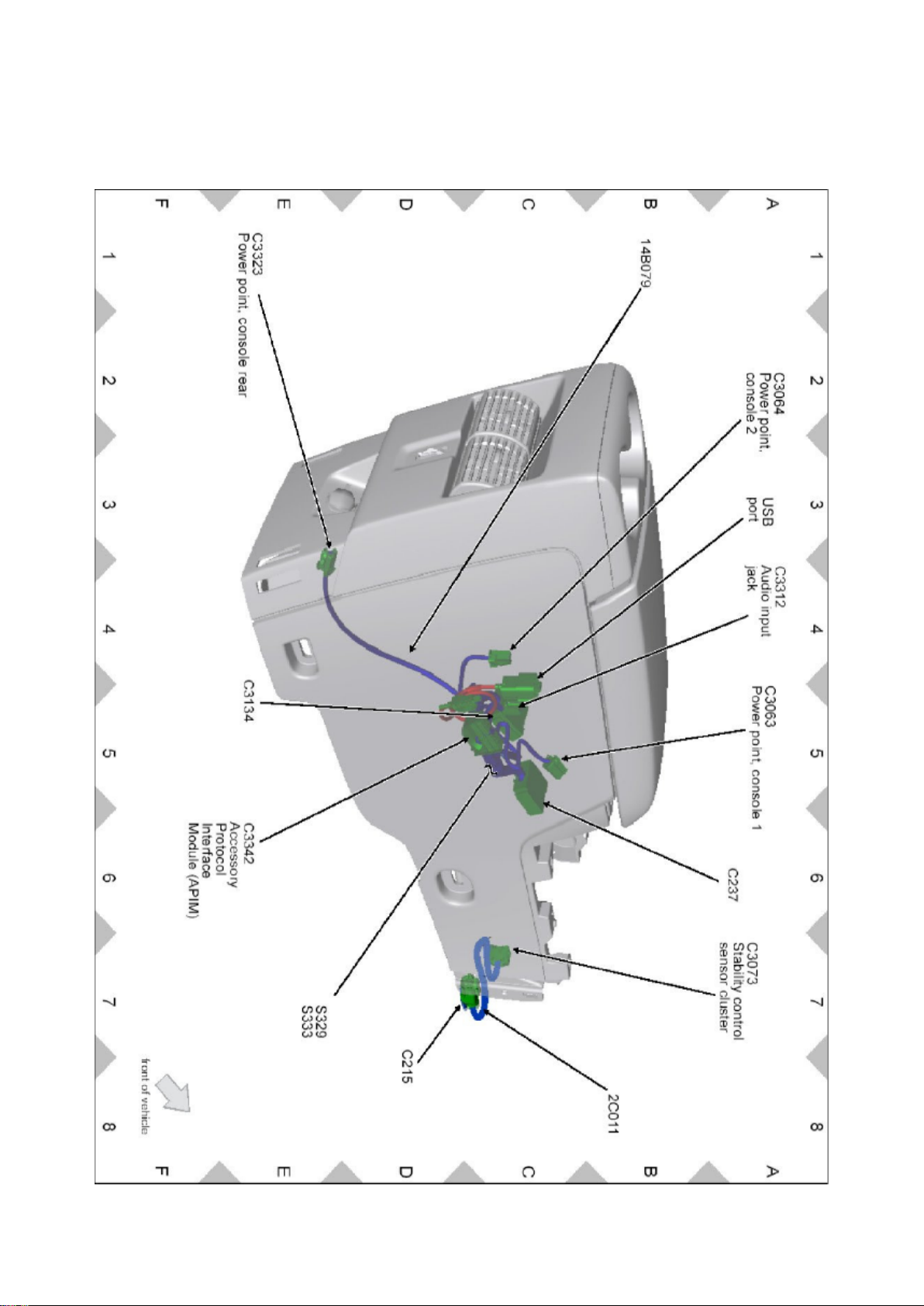
Ford Explorer 2wd Workshop Manual (V6-4.0L (2009))
Ford Workshop Manuals > Relays and Modules > Relays and Modules - Accessories and Optional Equipment >
Communications Control Module > Component Information > Locations > Accessory Protocol Interface Module (APIM)
Page 45

Page 46

Ford Explorer 2wd Workshop Manual (V6-4.0L (2009))
Ford Workshop Manuals > Relays and Modules > Relays and Modules - Accessories and Optional Equipment >
Communications Control Module > Component Information > Locations > Accessory Protocol Interface Module (APIM) >
Page 49
Page 47
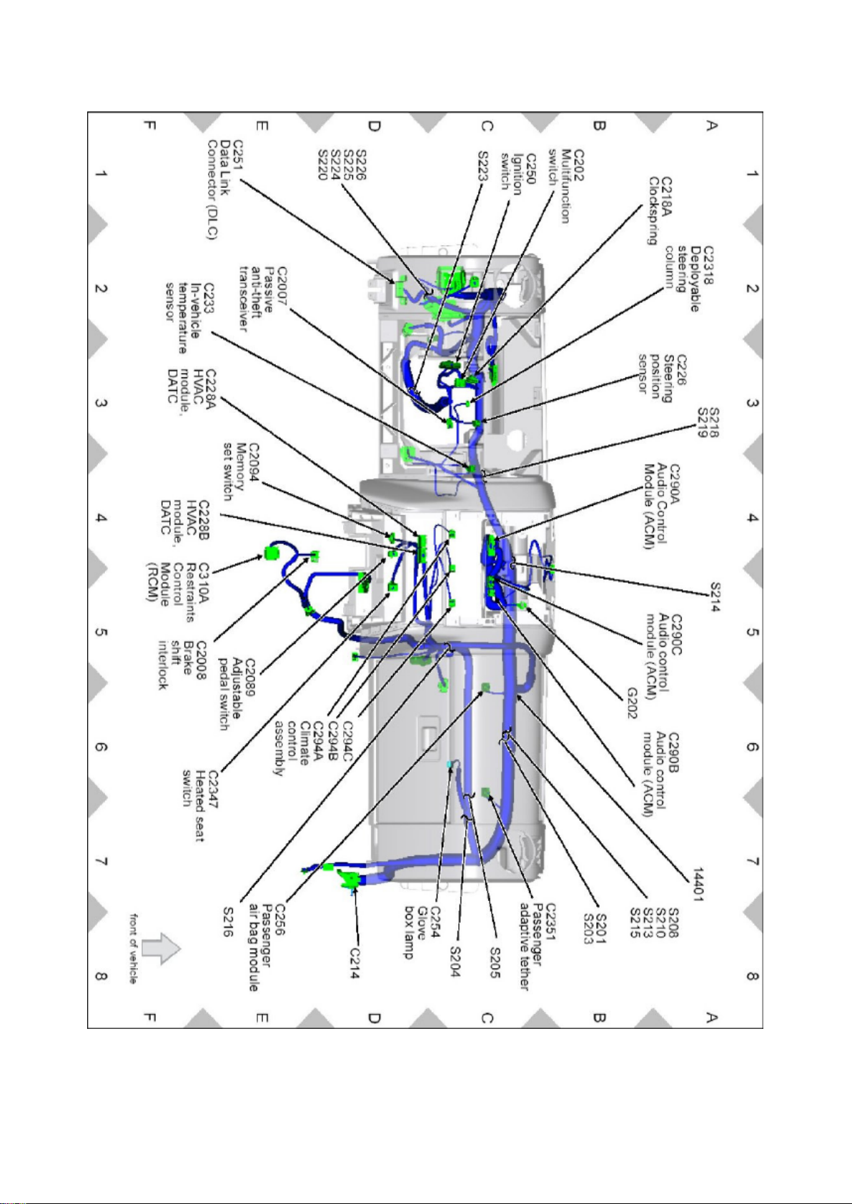
Page 48
Ford Explorer 2wd Workshop Manual (V6-4.0L (2009))
Ford Workshop Manuals > Relays and Modules > Relays and Modules - Accessories and Optional Equipment >
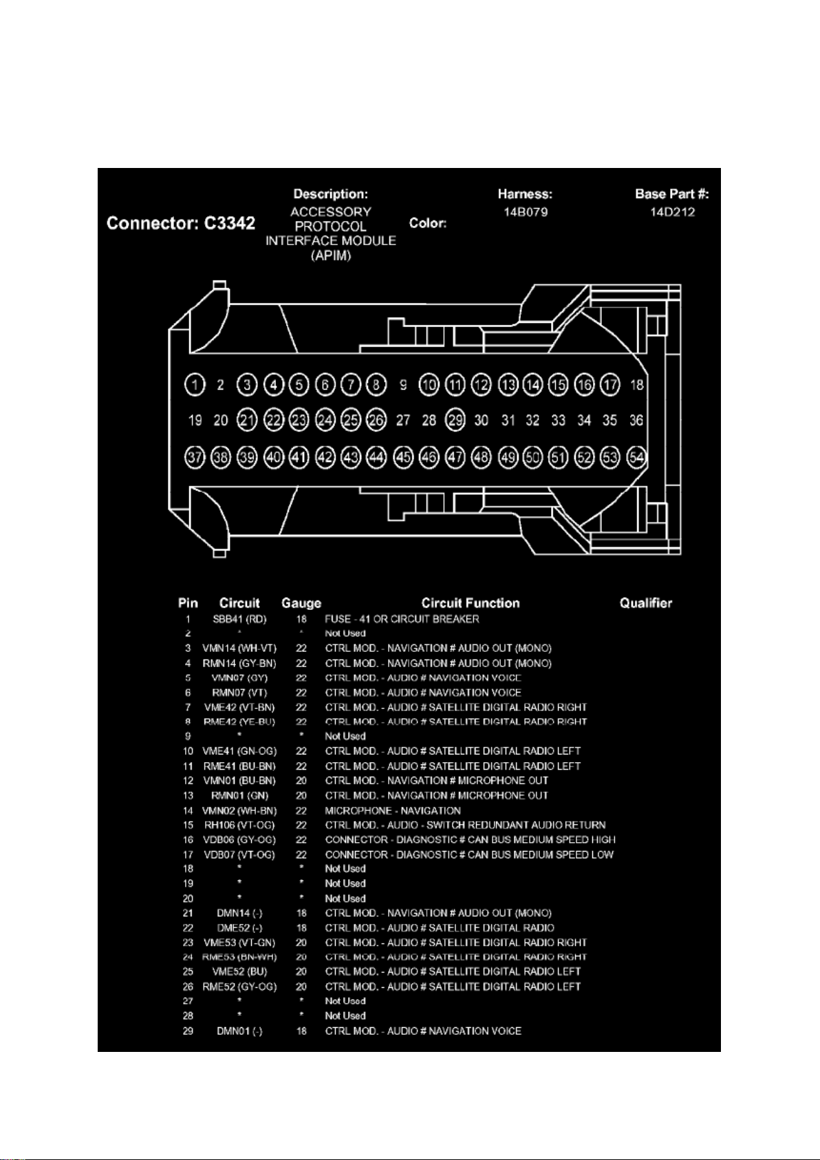
Communications Control Module > Component Information > Diagrams > Accessory Protocol Interface Module (APIM)
Page 49

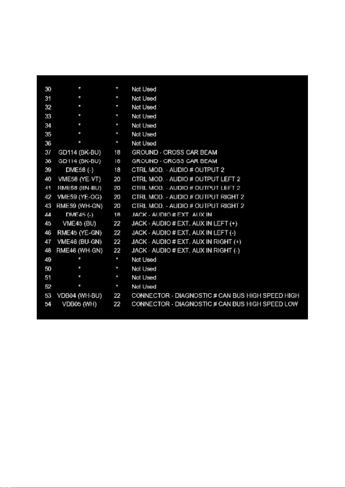
Communications Control Module: Diagrams Accessory Protocol Interface Module (APIM)
Part 1
Page 50
Ford Explorer 2wd Workshop Manual (V6-4.0L (2009))
Ford Workshop Manuals > Relays and Modules > Relays and Modules - Accessories and Optional Equipment >
Communications Control Module > Component Information > Diagrams > Accessory Protocol Interface Module (APIM) >
Page 52
Part 2
Page 51

Ford Explorer 2wd Workshop Manual (V6-4.0L (2009))
Ford Workshop Manuals > Relays and Modules > Relays and Modules - Accessories and Optional Equipment >
Communications Control Module > Component Information > Diagrams > Accessory Protocol Interface Module (APIM) >
Page 53
Page 52
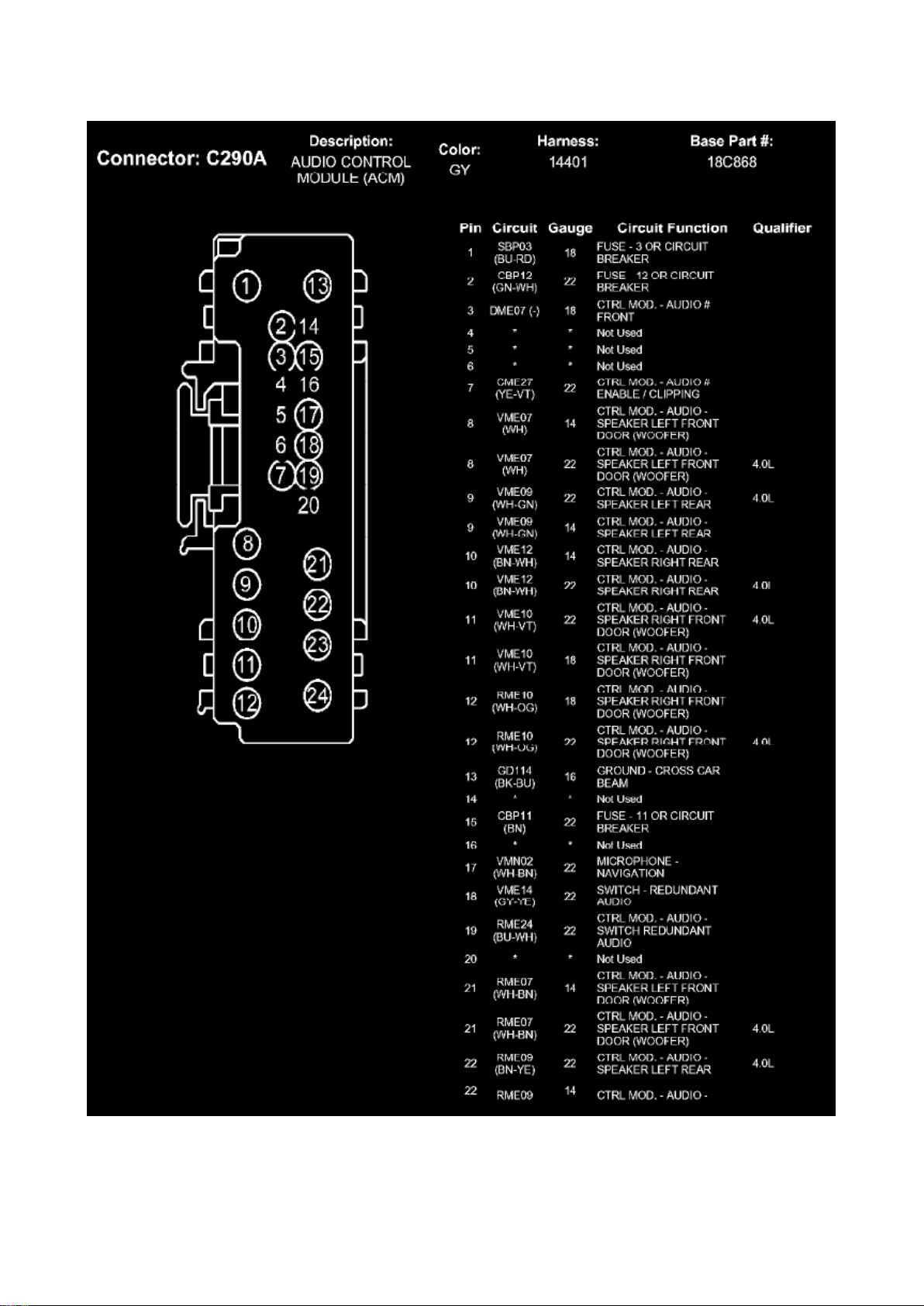
Communications Control Module: Diagrams Audio Control Module (ACM)
Page 53
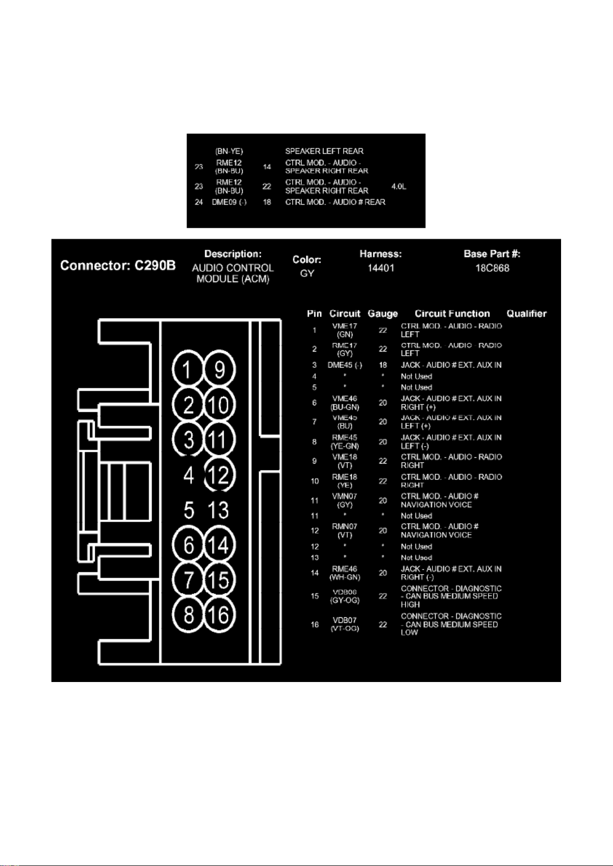
Ford Explorer 2wd Workshop Manual (V6-4.0L (2009))
Ford Workshop Manuals > Relays and Modules > Relays and Modules - Accessories and Optional Equipment >
Communications Control Module > Component Information > Diagrams > Accessory Protocol Interface Module (APIM) >
Page 54
Page 54
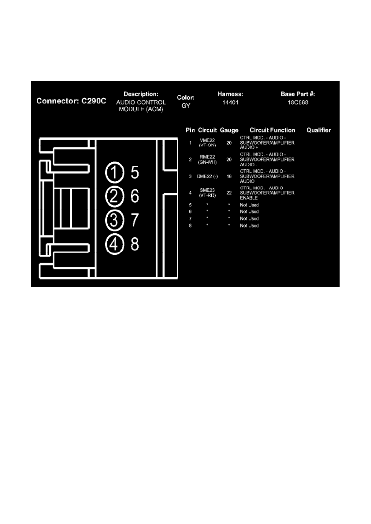
Ford Explorer 2wd Workshop Manual (V6-4.0L (2009))
Ford Workshop Manuals > Relays and Modules > Relays and Modules - Accessories and Optional Equipment >
Communications Control Module > Component Information > Diagrams > Accessory Protocol Interface Module (APIM) >
Page 55
Page 55
Ford Explorer 2wd Workshop Manual (V6-4.0L (2009))
Ford Workshop Manuals > Relays and Modules > Relays and Modules - Accessories and Optional Equipment >
Communications Control Module > Component Information > Service and Repair > Procedures
Communications Control Module: Procedures
Accessory Protocol Interface Module (APIM) Software Level Check
Accessory Protocol Interface Module (APIM) Software Level Check
NOTE: This procedure applies to checking the Accessory Protocol Interface Module (APIM)
software level. To program the APIM, refer to Accessory Protocol Interface Module (APIM)
Programming in Information Bus. See: Powertrain Management/Computers and Control
Systems/Information Bus/Testing and Inspection/Programming and Relearning/Accessory Protocol
Interface Module (APIM) Programming
1. Turn the Audio Control Module (ACM) on.
2. Connect the scan tool to the Data Link Connector (DLC).
3. Connect one end of the Universal Serial Bus (USB) male-A to male-A cable to the scan tool.
4. Connect the other end of the USB male-A to male-A cable to the vehicle USB port.
5. From the technician service publication website, run On-Line Automotive Service Information
System (OASIS) using Quick Start or by manually
entering the Vehicle Identification Number (VIN).
6. From the OASIS tab, select the "Sync/APIM" bullet.
7. Select the "Read APIM" button to verify the current APIM software level.
- The display shows both the Vehicle Interface Processor (VIP) and Consumer Interface Processor
(CIP) software levels.
8. The scan tool displays the following information:
- Last Recorded State - Hardware VIN: vehicle identification number associated with the current APIM
- Installed date: date the APIM was installed
Page 56

- Radio: currently identified ACM in the vehicle
- HW Part No.: APIM hardware part number
- Un-installed date: date (if any) the APIM was uninstalled
- S/N: APIM serial number
- Last Recorded State - Software Date/Time: date and time of last recorded software installation
- VIP: VIP software that was installed at that time
- CIP: CIP software that was installed at that time
Page 57

Ford Explorer 2wd Workshop Manual (V6-4.0L (2009))
Ford Workshop Manuals > Relays and Modules > Relays and Modules - Accessories and Optional Equipment >
Communications Control Module > Component Information > Service and Repair > Procedures > Page 58
Page 58

- Description: a description of the content of the software revision
- History - Software Date/Time: date and time of any recorded software installation
- VIP: VIP software that was installed at that time
- CIP: CIP software that was installed at that time
- Description: a description of the content of the software revision
- Available Software for Programming Select: allows the software package to be selected
- Lineage: the original software release, if the software available is a revision
- VIP: VIP software level that is available with the selection
- CIP: CIP software level that is available with the selection
- Description: a description of the content of the software revision
9. Click a CIP software level to view the device compatibility list associated with the CIP software
level, if desired.
10. To exit the APIM software level check, disconnect the scan tool from the DLC and the USB
port, or exit the OASIS screen.
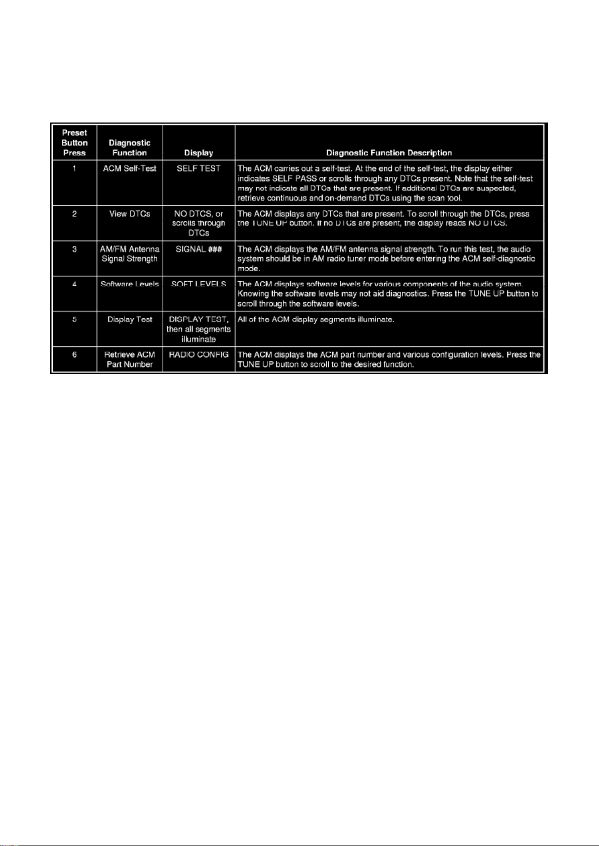
Audio Control Module (ACM) Self-Diagnostic Mode
Audio Control Module (ACM) Self-Diagnostic Mode
Audio Systems Without Navigation
1. Turn the Audio Control Module (ACM) on.
2. Operate the audio system in radio tuner (AM/FM) mode.
3. Press and hold preset buttons 3 and 6 for 3 seconds until the speaker walk test begins.
- The display indicates each speaker as it is tested.
4. NOTE: If the speaker walk test is the only test required, this procedure can be stopped after Step
3 by turning the ACM off.
Before the speaker walk test is complete, carry out any of the following actions:
Page 59
Ford Explorer 2wd Workshop Manual (V6-4.0L (2009))
Ford Workshop Manuals > Relays and Modules > Relays and Modules - Accessories and Optional Equipment >
Communications Control Module > Component Information > Service and Repair > Procedures > Page 59
5. To exit the self-diagnostic mode, turn the ACM off.
Satellite Digital Audio Receiver System (SDARS) Module Electronic Serial Number (ESN) Retrieval
- Vehicles Without Navigation
1. Operate the audio system in satellite radio mode.
2. Press and hold the AUX button and preset button 1, simultaneously.
- The Satellite Digital Audio Receiver System (SDARS) module Electronic Serial Number (ESN)
displays on the screen.
3. Record the SDARS module ESN.
4. Turn the audio system off.
Audio Systems With Navigation
1. Turn the Audio Control Module (ACM) on.
2. Operate the audio system in radio tuner (AM/FM) mode.
3. Press and hold preset buttons 3 and 6 for 3 seconds until the speaker walk test begins.
- The display indicates each speaker as it is tested.
4. NOTE: If the speaker walk test is the only test required, this procedure can be stopped after this
step, or by allowing the speaker walk test to
complete on its own.
Before the speaker walk test is complete, press the "End Test" selection.
Page 60
Ford Explorer 2wd Workshop Manual (V6-4.0L (2009))
Ford Workshop Manuals > Relays and Modules > Relays and Modules - Accessories and Optional Equipment >
Communications Control Module > Component Information > Service and Repair > Procedures > Page 60
Page 61

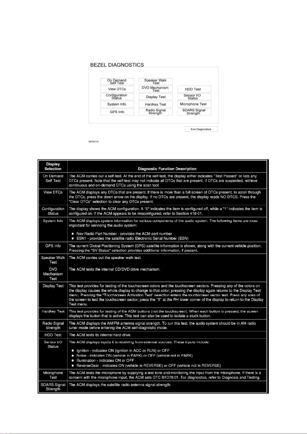
5. The following tests are available through the "BEZEL DIAGNOSTICS" menu:
6. To exit the self-diagnostic mode, press the "Exit Diagnostics" selection from the "BEZEL
DIAGNOSTICS" menu.
Page 62
Ford Explorer 2wd Workshop Manual (V6-4.0L (2009))
Ford Workshop Manuals > Relays and Modules > Relays and Modules - Accessories and Optional Equipment >
Communications Control Module > Component Information > Service and Repair > Procedures > Page 61
Communications Control Module: Removal and Replacement
Audio Control Module (ACM)
Audio Control Module (ACM)
Removal and Installation
NOTE: It is not necessary to remove the Audio Control Module (ACM) to retrieve the part number.
For additional information, refer to Audio Control Module (ACM) Self-Diagnostic Mode See:
Procedures/Audio Control Module (ACM) Self-Diagnostic Mode.
1. NOTE: Module configuration is required when a new ACM is being installed.
Upload the ACM configuration information to the scan tool.
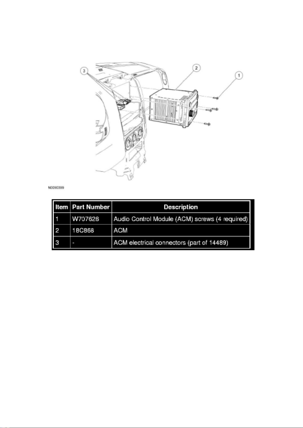
2. Remove the instrument panel center finish panel.
3. Remove the 4 screws and the ACM.
- Disconnect the ACM electrical connectors.
Page 63

4. To install, reverse the removal procedure.
- Download the configuration information to the ACM.
Accessory Protocol Interface Module (APIM)
Accessory Protocol Interface Module (APIM)
Floor Console Components
Page 64
Ford Explorer 2wd Workshop Manual (V6-4.0L (2009))
Ford Workshop Manuals > Relays and Modules > Relays and Modules - Accessories and Optional Equipment >
Communications Control Module > Component Information > Service and Repair > Procedures > Page 62
Page 65

Accessory Protocol Interface Module (APIM)
Removal and Installation
1. NOTE: It is necessary to record the current Accessory Protocol Interface Module (APIM)
software and hardware level when a new APIM is being
installed to make sure that the new component is the same version as the component being
replaced.
Retrieve and record the current APIM software and hardware level. For additional information, refer
to Accessory Protocol Interface Module (APIM) Software Level Check See: Procedures/Accessory
Protocol Interface Module (APIM) Software Level Check.
Page 66
Ford Explorer 2wd Workshop Manual (V6-4.0L (2009))
Ford Workshop Manuals > Relays and Modules > Relays and Modules - Accessories and Optional Equipment >
Communications Control Module > Component Information > Service and Repair > Procedures > Page 63
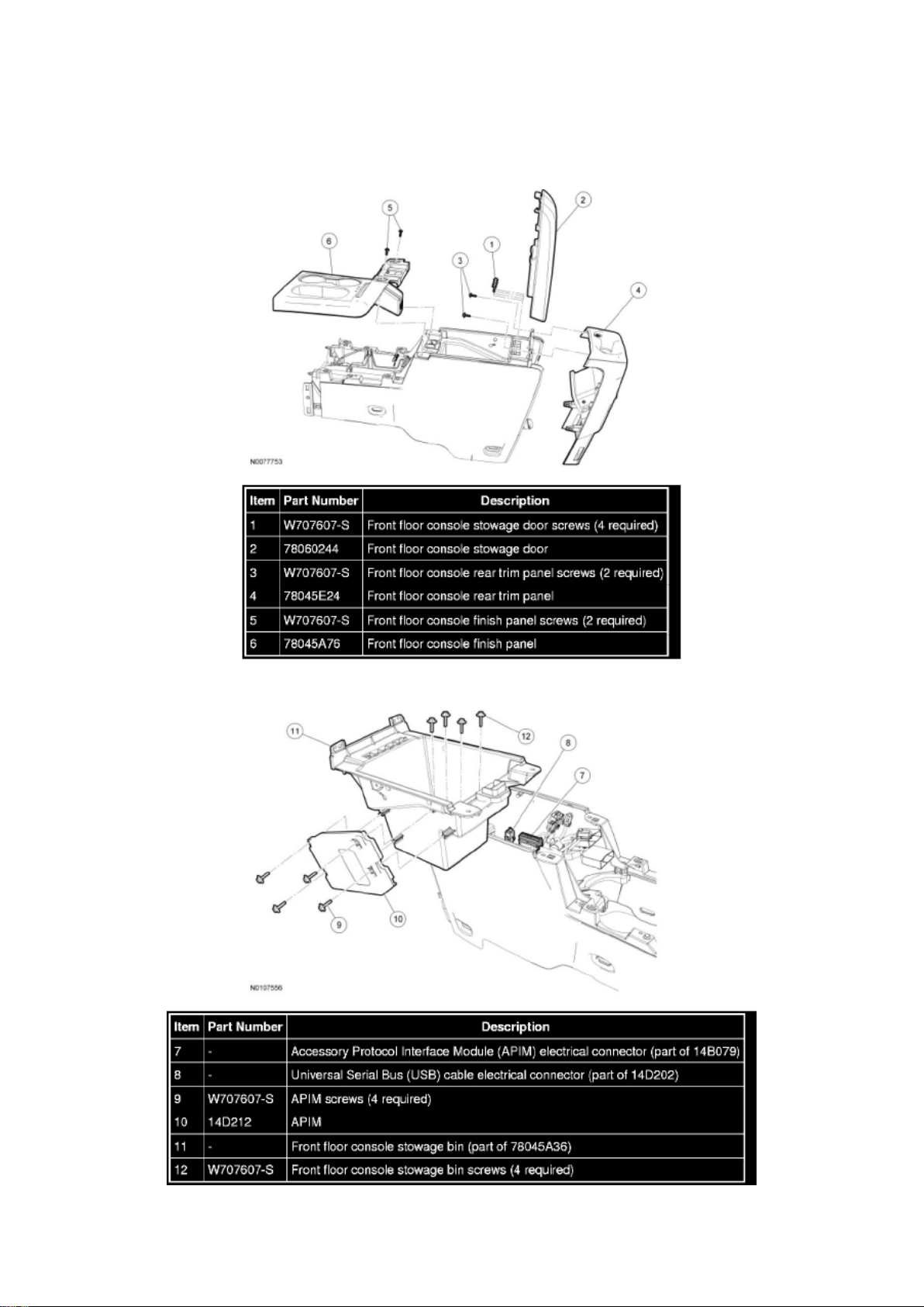
2. Remove the 4 screws and the front floor console stowage door.
3. Remove the 2 screws and the front floor console rear trim panel.
- Pull straight back to disengage the clips.
4. Remove the 2 screws and the front floor console finish panel.
- Pull straight up to disengage the clips.
5. Remove the front floor console stowage bin.
- Remove the 4 screws.
Page 67

- Disconnect the audio input jack electrical connector.
- Disconnect the Universal Serial Bus (USB) port electrical connector.
- Disconnect the APIM electrical connector.
- Disconnect the USB cable electrical connector (at the APIM).
6. Remove the 4 screws and the APIM.
7. To install, reverse the removal procedure.
- If a new APIM is being installed, program the APIM to the correct software level.
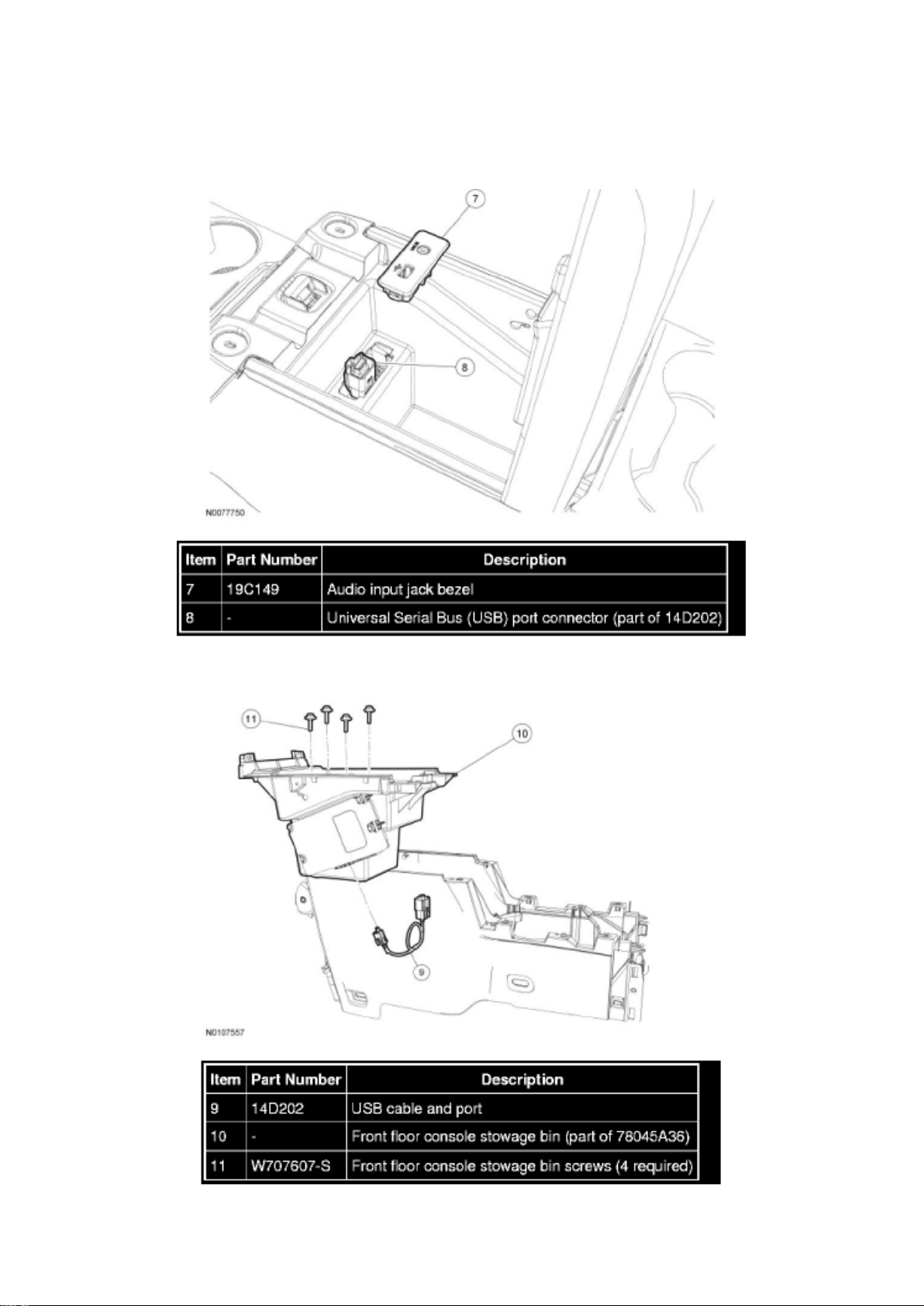
Universal Serial Bus (USB) Cable and Port
Universal Serial Bus (USB) Cable and Port
Floor Console Components
Universal Serial Bus (USB) Cable And Port-To-Bezel
Page 68
Ford Explorer 2wd Workshop Manual (V6-4.0L (2009))
Ford Workshop Manuals > Relays and Modules > Relays and Modules - Accessories and Optional Equipment >
Communications Control Module > Component Information > Service and Repair > Procedures > Page 64
Page 69

USB Cable And Port-To-Accessory Protocol Interface Module (APIM)
Removal and Installation
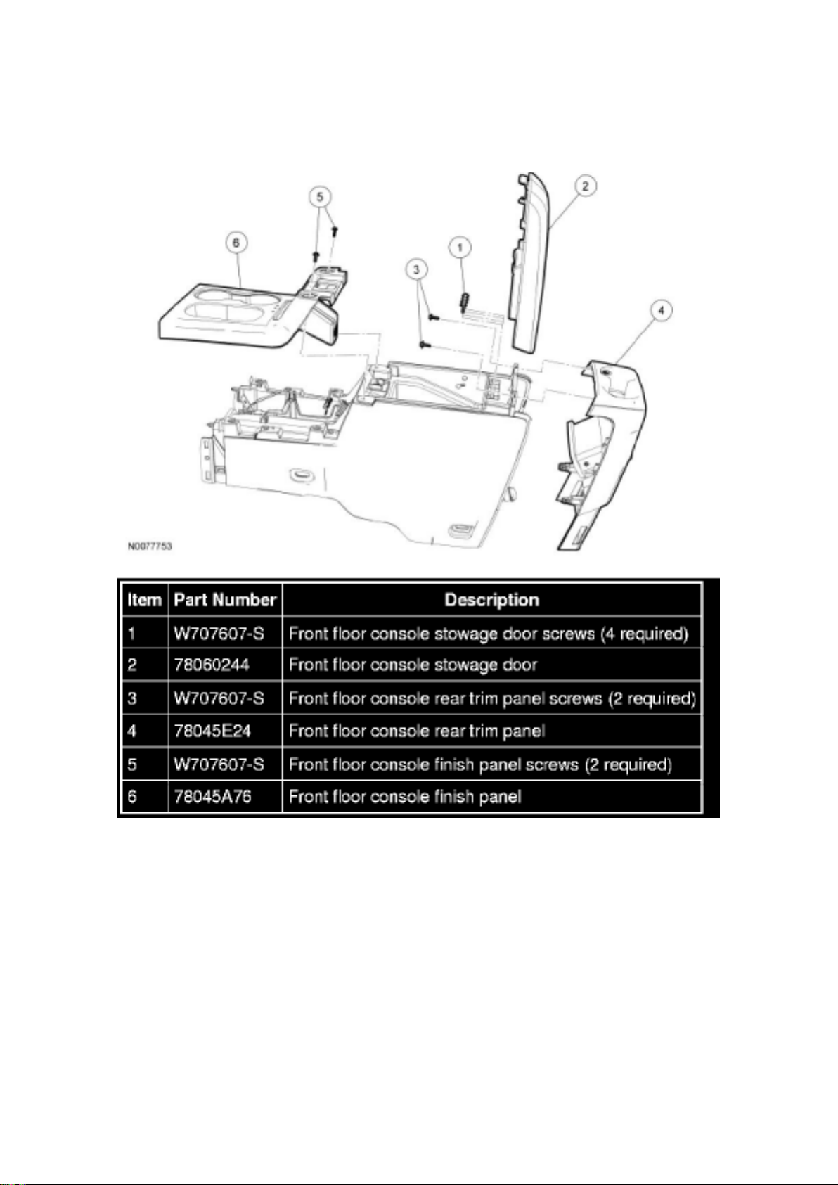
1. Remove the 4 screws and the front floor console stowage door.
2. Remove the 2 screws and the front floor console rear trim panel.
- Pull straight back to disengage the clips.
3. Remove the 2 screws and the front floor console finish panel.
- Pull straight up to disengage the clips.
4. Using a suitable tool (such as a trim removal tool) pry the audio input jack bezel from the storage
bin.
- Disconnect the audio input jack electrical connector.
5. Disconnect the Universal Serial Bus (USB) port connector from the audio input jack bezel.
6. Remove the 4 screws and the front floor console stowage bin.
Page 70

Ford Explorer 2wd Workshop Manual (V6-4.0L (2009))
Ford Workshop Manuals > Relays and Modules > Relays and Modules - Accessories and Optional Equipment >
Communications Control Module > Component Information > Service and Repair > Procedures > Page 65
Page 71

7. Remove the USB cable and port.
- Disconnect the electrical connector.
8. To install, reverse the removal procedure.
Page 72

Ford Explorer 2wd Workshop Manual (V6-4.0L (2009))
Ford Workshop Manuals > Relays and Modules > Relays and Modules - Accessories and Optional Equipment > Emergency
Contact Module > Component Information > Technical Service Bulletins > Customer Interest: > 09-14-3 > Jul > 09 >
SYNC(R) System - Functions Inoperative/DTC's Set
Page 73

Emergency Contact Module: Customer Interest SYNC(R) System - Functions Inoperative/DTC's
Set
Page 74

TSB 09-14-3
07/27/09
SYNC FUNCTIONS INOPERATIVE, DTC U3000-41, U0485, OR U0100, AND/OR BATTERY
DRAW WITH ACCESSORY PROTOCOL INTERFACE MODULE CONNECTED
FORD: 2008-2009 Focus, Taurus X, Taurus 2008-2010 Fusion 2010 Mustang 2008-2009 Edge,
Explorer Sport Trac, Explorer 2009 Escape Hybrid, Escape, Expedition, F-150, F-Super Duty, Flex
LINCOLN: 2008-2009 Zephyr 2008-2010 MKZ 2009 MKS 2008-2009 MKX, Navigator
MERCURY: 2008-2009 Sable 2008-2010 Milan 2008-2009 Mountaineer 2009 Mariner Hybrid,
Mariner
ISSUE Some 2008-2010 vehicles equipped with SYNC version 2 software level, SYNC 911 Assist
and Vehicle Health Report, may exhibit all or most of the following symptoms:
^ Diagnostic Trouble Codes (DTC) U3000-41, U0485, or U0100 in Accessory Protocol Interface
Module (APIM)
^ SYNC display menus/options blank
^ USB port inoperative
^ No SYNC Blue Tooth device connectivity
^ Voice/Phone/OK steering wheel controls inoperative
^ Lack of APIM communication
^ Parasitic battery draw with APIM connected
These symptoms may be triggered by a low battery state of charge, or a recent battery
disconnect/reconnect.
ACTION Follow the service procedure to correct the condition.
SERVICE PROCEDURE
This software upgrade only applies to the following Accessory Protocol Interface Module (APIM)
Vehicle Interface Processor (VIP) and Customer Interface Processor (CIP) software levels:
^ VIP: 9L2T-14D205-AC / CIP: 9L2T-14D544-BC
^ VIP: 9L2T-14D205-AD / CIP: 9L2T-14D544-BD
^ VIP: 9L2T-14D205-AE / CIP: 9L2T-14D544-BD
To determine the current APIM software level, reference the Professional Technician Society (PTS)
website, enter the VIN in OASIS, click the GO
Page 75

Ford Explorer 2wd Workshop Manual (V6-4.0L (2009))
Ford Workshop Manuals > Relays and Modules > Relays and Modules - Accessories and Optional Equipment > Emergency
Contact Module > Component Information > Technical Service Bulletins > Customer Interest: > 09-14-3 > Jul > 09 >
SYNC(R) System - Functions Inoperative/DTC's Set > Page 74
Page 76

button and select the SYNC button.
Page 77

1. Determine if communication can be established with the APIM using IDS.
a. If communication cannot be verified, proceed to Step 2.
b. If communication is present, proceed to Step 3.
2. Reference Workshop Manual, Section 418-00, Module Communication Network to determine if
communication can be established. If not, perform
an APIM power reset by disconnecting and reconnecting the vehicle battery.
a. If communication is now present, proceed to Step 3.
b. If communication still cannot be established, replace the APIM.
3. Reprogram the APIM to VIP software level 9L2T-14D205-AF by following the Service Procedure.
NOTE
SOFTWARE IS AVAILABLE ONLY THROUGH THE PTS WEBSITE, AND NOT AVAILABLE
THROUGH THE SYNCMYRIDE.COM WEBSITE.
NOTE
CONFIGURATION AND PROGRAMMING REQUIRES THE USE OF A SPECIAL PTS
APPLICATION. INSTALLER MUST HAVE ACCESS TO PTS AND HAVE A VALID PTS USER ID
AND PASSWORD.
a. Connect the vehicle communication module (VCM) to the data link connector (DLC).
b. Connect the VCM to the IDS tool or laptop running IDS software.
c. Turn the ignition key to the on position.
d. Launch IDS tool.
e. If required, update the VCM with the latest software.
f. Close the IDS tool.
g. From the PTS website, run OASIS by pressing the Read VIN And DTC's button. After vehicle
communication is established, press the GO
button.
h. From the Vehicle Service Session screen, Select the SYNC button.
i. Press read APIM button.
j. Select software and press program APIM to update the SYNC module.
NOTE
YOU MUST USE A MALE-A TO MALE-A USB CABLE LIKE ROTUNDA PART NUMBER
CCMU5B2-AM-AM-10 TO COMPLETE THIS STEP.
NOTE
DO NOT USE A TRANSFER TYPE CABLE.
NOTE
Page 78

DO NOT DISCONNECT THE VCM OR USB CABLES DURING APIM PROGRAMMING.
NOTE
THE SYSTEM MAY PROMPT YOU TO INSTALL SOFTWARE FOR THE USB PORT. FOLLOW
THE ON SCREEN INSTRUCTIONS TO INSTALL THE USB PORT DRIVER ALREADY
INCLUDED IN WINDOWS XP.
k. Program the processor in the APIM.
l. Connect the Male-A to Male-A USB cable, Rotunda part number CCMU5B2-AM-AM-10, to the
IDS tool or laptop running IDS software, and to the vehicle USB port.
m. Follow the on-screen instructions to program the VIP module.
Page 79

Ford Explorer 2wd Workshop Manual (V6-4.0L (2009))
Ford Workshop Manuals > Relays and Modules > Relays and Modules - Accessories and Optional Equipment > Emergency
Contact Module > Component Information > Technical Service Bulletins > Customer Interest: > 09-14-3 > Jul > 09 >
SYNC(R) System - Functions Inoperative/DTC's Set > Page 75
n. At the end of the configuration and programming procedure, the programming has been
completed successfully screen will be displayed.
o. Exit PTS, disconnect the VCM and disconnect the USB cable.
Parts Block
WARRANTY STATUS: Eligible Under Provisions Of New Vehicle Limited Warranty Coverage
IMPORTANT: Warranty coverage limits/policies are not altered by a TSB. Warranty coverage limits
are determined by the identified causal part.
OPERATION DESCRIPTION TIME
MT091403 Use SLTS Operations If Actual
Available; Claim Additional Time
Diagnosis Or Labor Performed As Actual Time
DEALER CODING
CONDITION
Page 80

BASIC PART NO. CODE
14D212 04
Disclaimer
Page 81

Ford Explorer 2wd Workshop Manual (V6-4.0L (2009))
Ford Workshop Manuals > Relays and Modules > Relays and Modules - Accessories and Optional Equipment > Emergency
Contact Module > Component Information > Technical Service Bulletins > Customer Interest: > 09-13-5 > Jul > 09 >
SYNC(R) System - Poor Cell Phone Sound Quality
Page 82

Emergency Contact Module: Customer Interest SYNC(R) System - Poor Cell Phone Sound Quality
Page 83

TSB 09-13-5
07/13/09
SYNC - CALL SOUND QUALITY/BACKGROUND NOISE ISSUES AND/OR VOICE
RECOGNITION DIFFICULTIES WHILE DRIVING
FORD: 2008-2009 Focus, Fusion, Taurus X, Taurus, Edge, Explorer Sport Trac, Explorer 2009
Escape Hybrid, Escape, Expedition, F-150, F-Super Duty, Flex
LINCOLN: 2008-2009 MKZ 2009 MKS 2008-2009 MKX, Navigator
MERCURY: 2008-2009 Milan, Sable, Mountaineer 2009 Mariner Hybrid, Mariner
ISSUE Some customers of 2008-2009 SYNC equipped vehicles may express concern with their
call sound quality while using the SYNC microphone, complaints of excessive background noise
during a phone call, and/or issues with voice recognition accuracy while driving.
ACTION Follow the service procedure to correct the condition.
SERVICE PROCEDURE
The following service procedure involves updating the Accessory Protocol Interface Module (APIM)
software level and installing an external alternate SYNC microphone attached to the headliner.
NOTE
THIS PROCEDURE DOES NOT APPLY TO DEALER-INSTALLED SYNC SYSTEMS.
Do not perform Step 1 if vehicle is already equipped with SYNC 2.0 (911 and Vehicle Health
Report) or has been upgraded to consumer interface processor (CIP) level 9L3T-14D544-AE. To
determine the current APIM software level, Refer to the Professional Technician Society (PTS)
website, enter the VIN in OASIS, click the GO button, and select the SYNC button.
1. Reprogram the APIM to CIP software level 9L3T-14D544-AE. For additional information Refer to
other SYNC TSB's and WSM, Section 418-01.
Service Pack files may also be obtained at www.syncmyride.com.
When diagnosing a concern related to voice recognition (VR) difficulties, instruct the customer to
test VR functionality while the vehicle is parked. If customer concerns are still present, this
procedure will not yield an improvement, and the service procedure should not be performed.
Instead, Refer to the SYNC supplement guide and www.syncmyride.com for additional VR tips to
assist customer.
The VR experience can be improved with user training and making improvements to the phone
book entries (longer entries make the system more robust). Ensure the customer does not try to
speak too loud or slow and remove any objects hanging on the rear view mirror as this will reduce
system effectiveness.
When diagnosing a concern related to call sound quality, expect marginal improvements for calls
described as speaking in a tunnel, chamber, etc. Expect substantial improvements for complaints
where the call audio seems to drop out intermittently.
NOTE
THIS REPAIR WILL CHANGE THE APPEARANCE OF THE VEHICLE INTERIOR. REFER TO
THE PHOTOGRAPHS FOR THE APPLICABLE VEHICLE LOCATED IN THIS PROCEDURE. DO
NOT PERFORM THIS REPAIR WITHOUT CUSTOMER APPROVAL PRIOR TO PROCEEDING
WITH MICROPHONE INSTALLATION.
Page 84

2. Install SYNC microphone service kit. Installing the kit includes mounting an external microphone
directly to the headliner and splicing in a jumper
harness to the vehicle's existing wiring harness. The existing SYNC microphone will no longer be
functional.
Page 85
Ford Explorer 2wd Workshop Manual (V6-4.0L (2009))
Ford Workshop Manuals > Relays and Modules > Relays and Modules - Accessories and Optional Equipment > Emergency
Contact Module > Component Information > Technical Service Bulletins > Customer Interest: > 09-13-5 > Jul > 09 >
SYNC(R) System - Poor Cell Phone Sound Quality > Page 80
a. Refer to the appropriate vehicle line and microphone illustration(s) below for microphone
installation and wire splicing locations. Refer to
Wiring Diagram (WD), Section 5-1 for recommended splicing methods.
b. Ensure the SYNC microphone wires are secure and do not interfere with vehicle operation or
functionality.
c. The microphone is directional. Make sure the microphone is always positioned so wire length is
minimized from view. When installing the
microphone adjacent to trim, place microphone as close to trim as possible to help minimize visible
wire.
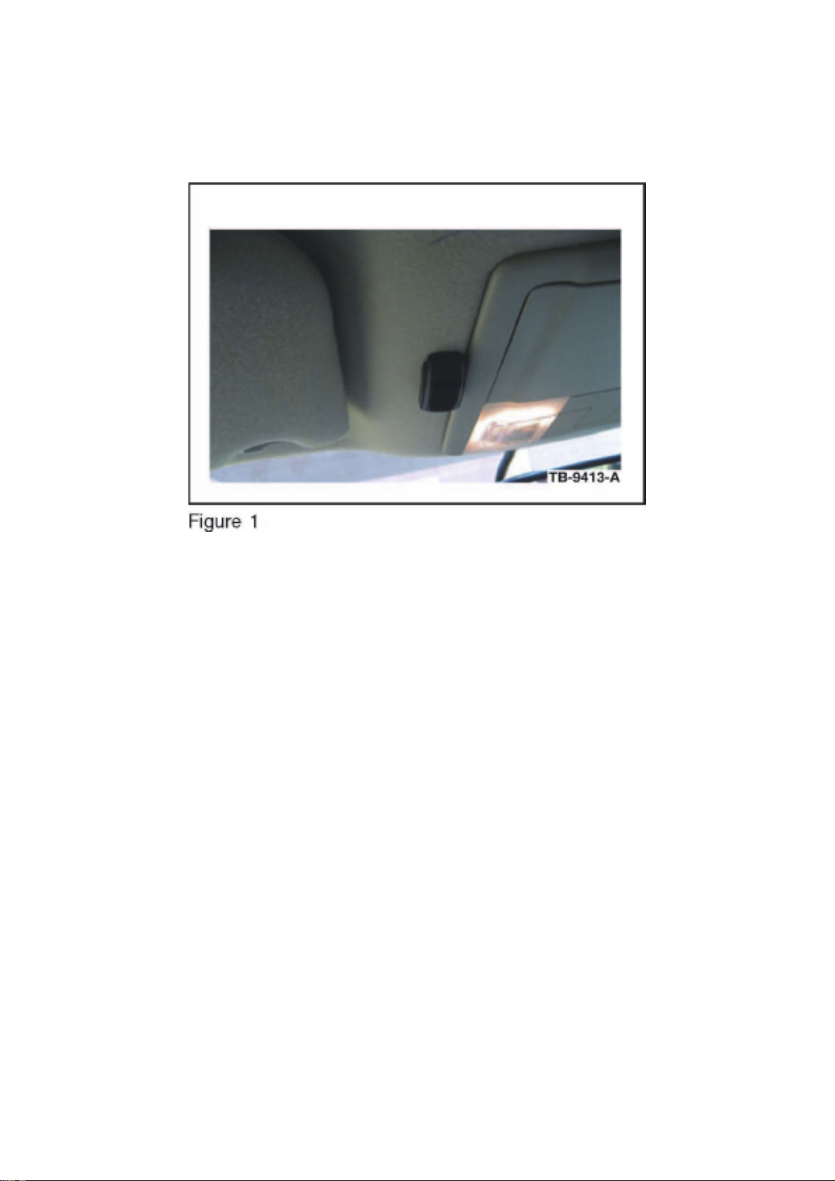
2008-2009 Edge / MKX
1. Remove the protective backing from the adhesive on the microphone and attach the
microphone. (Figure 1)
^ Firmly press the microphone into place.
^ Ensure the microphone is parallel and adjacent to overhead console trim.
2. Lower the overhead console. Refer to WSM, Section 417-02 for additional information.
3. Route microphone cable up through existing hole in the headliner, and over to the driver side
A-pillar. It may be necessary to slightly drop headliner
to run microphone cable. Refer to WSM, Section 501-05 for additional information.
4. Install overhead console; ensure microphone cable enters the overhead console trim directly
behind microphone as shown.
Page 86

5. Gain access to connectors 210 and 211 in the left A-pillar. Refer to online WD, Section 124-1 for
links to location and connector views.
6. Identify circuits VMM13 (YE-GN), RMM13 (BU), and DMM13 (shield) from C211. Cut the three
circuits on the female side of the connector
(14334 harness).
7. Identify circuits CBP41 (BU) and GD133 (BK) from C210.
8. Splice the five jumper harness wires into the following circuits:
^ Blue jumper harness wire to CBP41 (BU) and any black jumper harness wire to GD133 (BK).
^ Ensure original circuits remain connected in splice.
^ Yellow jumper harness wire to VMM13 (YE-GN) and remaining black jumper harness wires to
RMM13 (BU) and DMM13 (shield).
^ Only splice into the cut wires heading in the direction of the connector. Tape off and secure the
cut wire ends heading up the A-pillar as they are no longer used.
9. Attach the microphone connector to the jumper harness connector.
10. Bundle and tuck the remainder of the microphone cable over the front of the headliner.
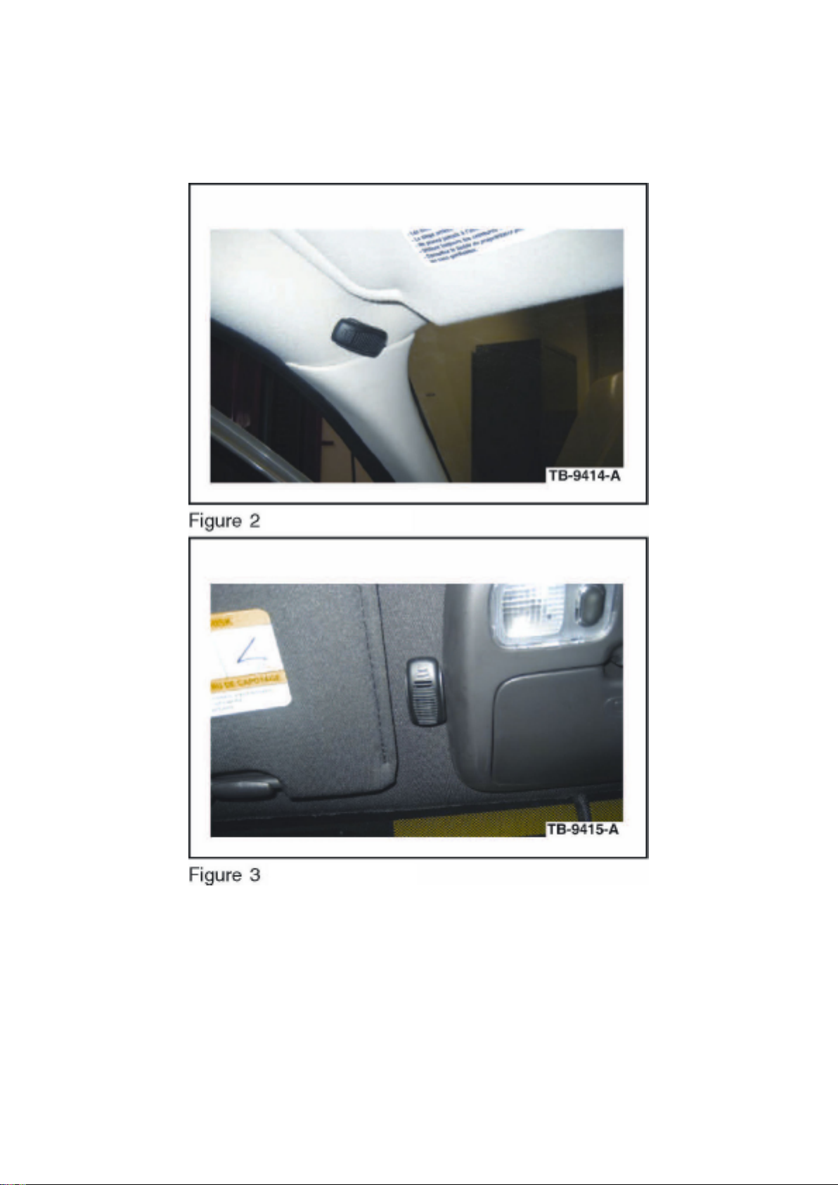
2009 Escape / Mariner
Page 87
Ford Explorer 2wd Workshop Manual (V6-4.0L (2009))
Ford Workshop Manuals > Relays and Modules > Relays and Modules - Accessories and Optional Equipment > Emergency
Contact Module > Component Information > Technical Service Bulletins > Customer Interest: > 09-13-5 > Jul > 09 >
SYNC(R) System - Poor Cell Phone Sound Quality > Page 81
1. Remove the protective backing from the adhesive on the microphone and attach the microphone
as shown in the illustration (Figures 2 and 3). Firmly
press the microphone into place. Ensure the microphone is parallel and adjacent to overhead
console trim (if equipped), or positioned directly above A-pillar on headliner if not equipped with an
overhead console. Proceed to Step 5 if not equipped with an overhead console.
2. Lower the overhead console. Refer to WSM, Section 501-05 for additional information.
Page 88

3. Route microphone cable through existing hole in the headliner, and over to the driver side
A-pillar. It may be necessary to slightly drop headliner to
run microphone cable.
4. Install overhead console; ensure microphone cable enters the overhead console trim directly
behind microphone as shown.
5. Gain access to connector 214 in the left A-pillar. Refer to online WD, Section 124-1 for links to
location and connector views.
6. Identify circuits VMM13 (YE-GN), RMM13 (BU), and DMM13 (shield) from C214. Cut the three
circuits on the female side of the connector
(14334 harness).
7. Identify circuits CBP41 (BU) and GD182 (BK-GY) from C214.
8. Splice the five jumper harness wires into the following circuits:
^ Blue jumper harness wire to CBP41 (BU) and any black jumper harness wire to GD1 82 (BK-GY).
^ Ensure original circuits remain connected in splice.
^ Yellow jumper harness wire to VMM13 (YE-GN) and remaining black jumper harness wires to
RMM13 (BU) and DMM13 (shield).
^ Only splice into the cut wires heading in the direction of the connector. Tape off and secure the
cut wire ends heading up the A-pillar as they are no longer used.
9. Connect the microphone connector to the jumper harness connector.
10. Bundle and tuck the remainder of the microphone cable over the front of the headliner.
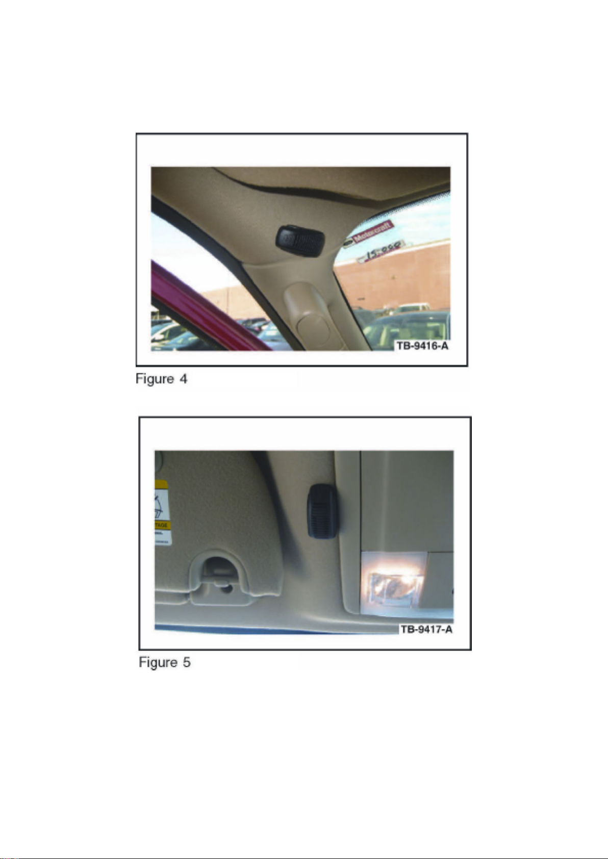
2008-2009 Navigator / 2009 Expedition
Page 89
Ford Explorer 2wd Workshop Manual (V6-4.0L (2009))
Ford Workshop Manuals > Relays and Modules > Relays and Modules - Accessories and Optional Equipment > Emergency
Contact Module > Component Information > Technical Service Bulletins > Customer Interest: > 09-13-5 > Jul > 09 >
SYNC(R) System - Poor Cell Phone Sound Quality > Page 82
1. Remove the protective backing from the adhesive on the microphone and attach the
microphone. (Figures 4 and 5)
^ Firmly press the microphone into place.
^ Ensure the microphone is parallel and adjacent to overhead console trim (if equipped), or
positioned directly above A-pillar on headliner if not
Page 90

equipped with an overhead console.
^ Proceed to Step 5 if not equipped with an overhead console.
2. Lower the overhead console. Refer to WSM, Section 417-02 for additional information.
3. Route microphone cable through existing hole in the headliner, and over to the passenger side
A-pillar. It may be necessary to slightly drop headliner
to run microphone cable. Refer to WSM, Section 501-05 for additional information.
4. Install overhead console; ensure microphone cable enters the overhead console trim directly
behind microphone as shown.
5. Gain access to connector 298 located behind the dash panel on passenger side. Refer to online
WD, Section 124-1 for links to location and connector
views.
6. Identify circuits VMN07 (GY), RMN07 (VT), and DMN07 (shield - BK) from C298. Cut the three
circuits on the male side of the connector
(17C712 harness).
7. Identify circuits CBP31 (BU-OG) and GD133 (BK) from C298 (2008 Navigator only). Identify
circuits CBP41 (BU) and GD133 (BK) from C298
(2009 Expedition/Navigator only).
8. Splice the five jumper harness wires into the following circuits:
^ Blue jumper harness wire to CBP31 (BU-OG) and any black jumper harness wire to GD133 (BK)
for 2008 Navigator only. Blue jumper harness wire to CBP41 (BU) and any black jumper harness
wire to GD133 (BK) for 2009 Expedition/Navigator only.
^ Ensure original circuits remain connected in splice.
Page 91
Ford Explorer 2wd Workshop Manual (V6-4.0L (2009))
Ford Workshop Manuals > Relays and Modules > Relays and Modules - Accessories and Optional Equipment > Emergency
Contact Module > Component Information > Technical Service Bulletins > Customer Interest: > 09-13-5 > Jul > 09 >
SYNC(R) System - Poor Cell Phone Sound Quality > Page 83
^ Yellow jumper harness wire to VMN07 (GY) and remaining black jumper harness wires to RMN07
(VT) and DMN07 (shield - BK).
^ Only splice into the cut wires heading in the direction of the connector. Tape off and secure the
other cut wire ends as they are no longer used.
9. Connect the microphone connector to the jumper harness connector.
10. Bundle and tuck the remainder of the microphone cable above the headliner.
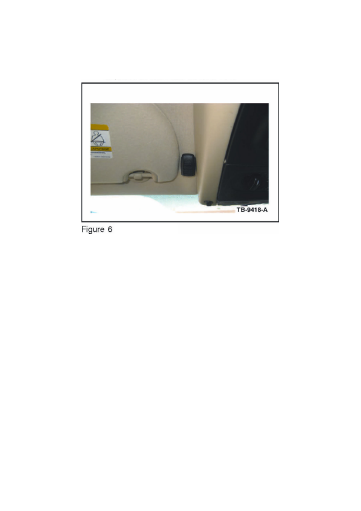
2008-2009 Explorer / Explorer Sport Trac / Mountaineer
1. Remove the protective backing from the adhesive on the microphone and attach the
microphone. (Figure 6)
^ Firmly press the microphone into place.
^ Ensure the microphone is parallel and adjacent to overhead console trim.
2. Lower the overhead console. Refer to WSM, Section 417-02 for additional information.
3. Route microphone cable through existing hole in the headliner, and over to the driver side
A-pillar. It may be necessary to slightly drop headliner run
microphone cable. Refer to WSM, Section 501-05 for additional information.
4. Install overhead console; ensure microphone cable enters the overhead console trim directly
behind microphone as shown.
5. Gain access to connector 248 in the left A-pillar. Refer to online WD, Section 124-1 for links to
location and connector views.
Page 92

6. Identify and cut circuits VMNO7 (GY), RMNO7 (VT), and DMNO7 (shield) from C248. Cut the
three circuits on the female side of the connector
(14334 harness).
7. Identify circuits CBP05 (YE) and GD143 (BK-VT) from C248.
8. Splice the five jumper harness wires into the following circuits:
^ Blue jumper harness wire to CBP05 (YE) and any black jumper harness wire to GD143 (BK-VT).
^ Ensure original circuits remain connected in splice.
^ Yellow jumper harness wire to VMN07 (GY) and remaining black jumper harness wires to RMN07
(VT) and DMN07 (shield).
^ Only splice into the cut wires heading in the direction of the connector. Tape off and secure the
cut wire ends heading up the A-pillar as they are no longer used.
9. Attach the microphone connector to the jumper harness connector.
10. Bundle and tuck the remainder of the microphone cable over the front of the headliner.
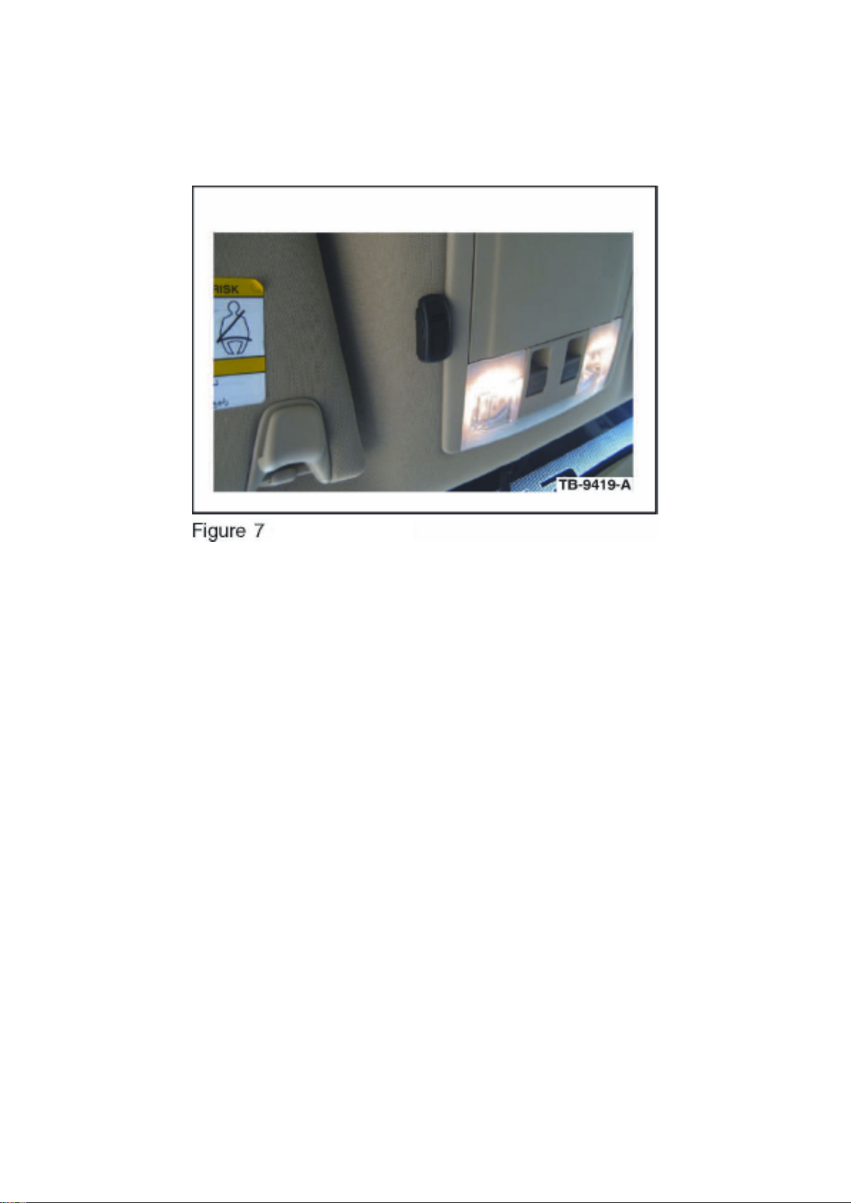
2009 F-150
Page 93
Ford Explorer 2wd Workshop Manual (V6-4.0L (2009))
Ford Workshop Manuals > Relays and Modules > Relays and Modules - Accessories and Optional Equipment > Emergency
Contact Module > Component Information > Technical Service Bulletins > Customer Interest: > 09-13-5 > Jul > 09 >
SYNC(R) System - Poor Cell Phone Sound Quality > Page 84
1. Remove the protective backing from the adhesive on the microphone and attach the
microphone. (Figure 7)
^ Firmly press the microphone into place.
^ Ensure the microphone is parallel and adjacent to overhead console trim or front lamp.
2. Lower the overhead console or front lamp. Refer to WSM, Section 417-02 for additional
information.
3. Route microphone cable through existing hole in the headliner, and temporarily tuck excess wire
into headliner to the rear of the console or lamp.
4. Install overhead console or front lamp; ensure microphone cable enters the overhead console or
front lamp trim directly behind microphone as
shown.
5. Gain access to connectors 314 and 315 in roof panel near left hand side. Refer to online WD,
Section 124-1 for links to location and connector
views.
6. Identify circuits VMM13 (YE-GN), RMM13 (BU), and DMM13 (shield) from C314. Cut the three
circuits on the female side of the connector
(14358 harness).
7. Identify circuits CBP41 (BU) from C315 and GD133 (BK) from C314.
8. Splice the five jumper harness wires into the following circuits:
Page 94

^ Blue jumper harness wire to CBP41 (BU) and any black jumper harness wire to GD133 (BK).
^ Ensure original circuits remain connected in splice.
^ Yellow jumper harness wire to VMM13 (YE-GN) and remaining black jumper harness wires to
RMM13 (BU) and DMM13 (shield).
^ Only splice into the cut wires heading in the direction of the connector. Tape off and secure the
other cut wire ends as they are no longer used.
9. Attach the microphone connector to the jumper harness connector.
10. Bundle and tuck the remainder of the microphone cable above the headliner.
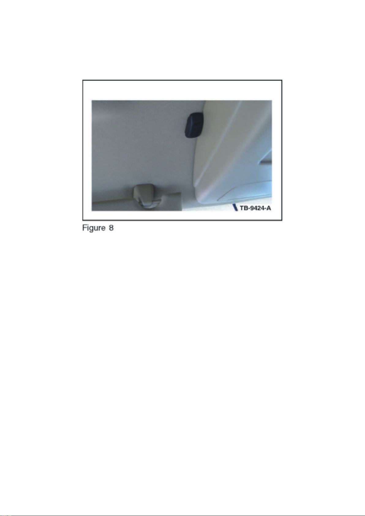
2009 F-Super Duty
Page 95
Ford Explorer 2wd Workshop Manual (V6-4.0L (2009))
Ford Workshop Manuals > Relays and Modules > Relays and Modules - Accessories and Optional Equipment > Emergency
Contact Module > Component Information > Technical Service Bulletins > Customer Interest: > 09-13-5 > Jul > 09 >
SYNC(R) System - Poor Cell Phone Sound Quality > Page 85
1. Remove the protective backing from the adhesive on the microphone and attach the microphone
as shown in the illustration. (Figure 8)
a. Firmly press the microphone into place.
b. Ensure the microphone is parallel and adjacent to overhead console trim.
c. This repair is not recommended for vehicles not equipped with an overhead console.
2. Lower the overhead console. Refer to WSM, Section 417-02 for additional information.
3. Route microphone cable through existing hole in the headliner, and over to the passenger side
A-pillar. It may be necessary to slightly drop headliner
to run microphone cable. Refer to WSM, Section 501-05 for additional information.
4. Install overhead console; ensure microphone cable enters the overhead console trim directly
behind microphone as shown.
5. Gain access to connector 264 in the right A-pillar. Refer to online WD, Section 124-1 for links to
location and connector views.
6. Identify circuits VMM13 (YE-GN), RMM13 (BU), and DMM13 (shield - BK) from C264. Cut the
three circuits on the female side of the connector
(17K745 harness).
7. Identify circuits CBP41 (BU) and GD133 (BK) from C264.
8. Splice the five jumper harness wires into the following circuits:
^ Blue jumper harness wire to CBP41 (BU) and any black jumper harness wire to GD133 (BK).
Page 96

^ Ensure original circuits remain connected in splice.
^ Yellow jumper harness wire to VMM13 (YE-GN) and remaining black jumper harness wires to
RMM13 (BU) and DMM13 (shield - BK).
^ Only splice into the cut wires heading in the direction of the connector. Tape off and secure the
other cut wire ends as they are no longer used.
9. Connect the microphone connector to the jumper harness connector.
10. Bundle and tuck the remainder of the microphone cable above the front of the headliner.
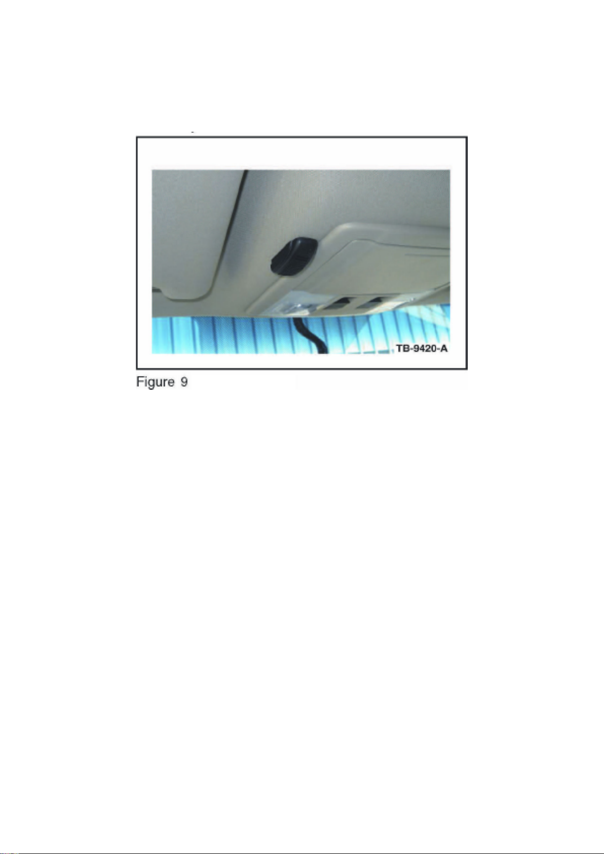
2009 Flex
Page 97
Ford Explorer 2wd Workshop Manual (V6-4.0L (2009))
Ford Workshop Manuals > Relays and Modules > Relays and Modules - Accessories and Optional Equipment > Emergency
Contact Module > Component Information > Technical Service Bulletins > Customer Interest: > 09-13-5 > Jul > 09 >
SYNC(R) System - Poor Cell Phone Sound Quality > Page 86
1. Remove the protective backing from the adhesive on the microphone and attach the microphone
as shown in the illustration. (Figure 9)
^ Firmly press the microphone into place.
^ Ensure the microphone is parallel and adjacent to overhead console trim.
2. Lower the overhead console. Refer to WSM, Section 417-02 for additional information.
3. Route microphone cable through existing hole in the headliner, and over to the passenger side
A-pillar. It may be necessary to slightly drop headliner
to run microphone cable. Refer to WSM, Section 501-05 for additional information.
4. Install overhead console; ensure microphone cable enters the overhead console trim directly
behind microphone as shown.
5. Gain access to connector 925 in the right A-pillar. Refer to online WD, Section 124-1 for links to
location and connector views.
6. Identify circuits VMM13 (YE-GN), RMM13 (BU), and DMM13 (shield) from C925. Cut the three
circuits on the female side of the connector (14334 harness).
7. Identify circuits CBP41 (BU) and GD133 (BK) from C925.
8. Splice the five jumper harness wires into the following circuits:
^ Blue jumper harness wire to CBP41 (BU) and any black jumper harness wire to GD133 (BK).
^ Ensure original circuits remain connected in splice.
Page 98

^ Yellow jumper harness wire to VMM13 (YE-GN) and remaining black jumper harness wires to
RMM13 (BU) and DMM13 (shield).
^ Only splice into the cut wires heading in the direction of the connector. Tape off and secure the
other cut wire ends as they are no longer used.
9. Attach the microphone connector to the jumper harness connector.
10. Bundle and tuck the remainder of the microphone cable above the front of the headliner.
2008-2009 Focus
Page 99

Ford Explorer 2wd Workshop Manual (V6-4.0L (2009))
Ford Workshop Manuals > Relays and Modules > Relays and Modules - Accessories and Optional Equipment > Emergency
Contact Module > Component Information > Technical Service Bulletins > Customer Interest: > 09-13-5 > Jul > 09 >
SYNC(R) System - Poor Cell Phone Sound Quality > Page 87
Page 100
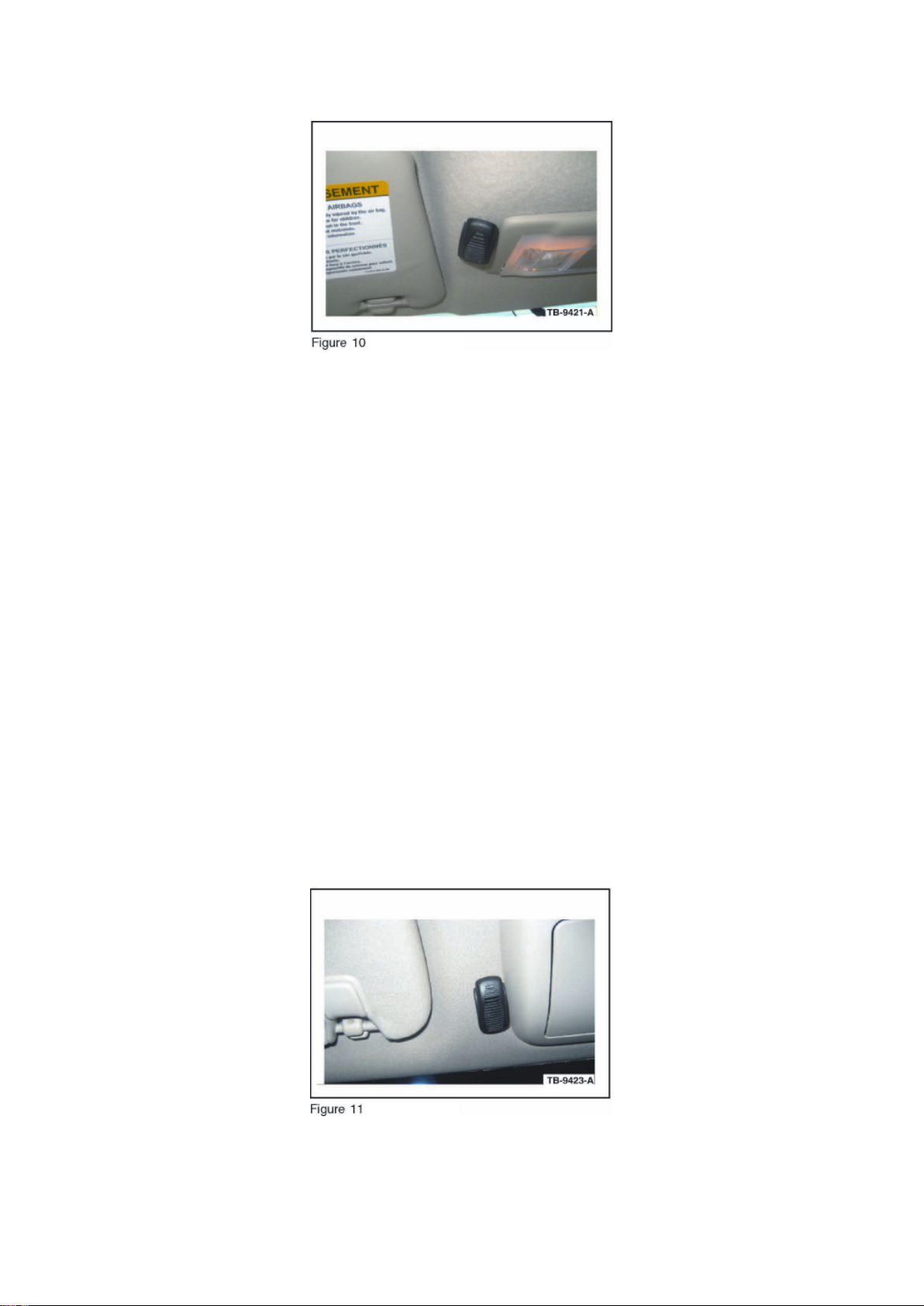
1. Remove the protective backing from the adhesive on the microphone and attach the microphone
as shown in the illustration (Figure 10). Firmly press
 Loading...