

Page 1

Factory Workshop Manual
Ford
Expedition 2wd
V8-281 4.6L VIN W EFI (1997)
Anonymous
1st January 2018
Make
Model
Engine and year
This manual was submitted by
Date
Page 2

Ford Expedition 2wd Workshop Manual (V8-281 4.6L VIN W EFI (1997))
Ford Workshop Manuals > A L L Diagnostic Trouble Codes ( DTC ) > Codes by Number > P0500-P05ZZ > P0500 - P0504,
( P0501 P0502 P0503 0500 0501 0502 0503 0504 ) > System Information > System Diagnosis > P0500 ( P 0500 )
Page 3

P0500 - P0504: Testing and Inspection P0500 ( P 0500 )
For diagnosis of P0500 refer to the system experiencing the problem.
Computers and Control Systems or Transmission Control System
Refer to pinpoint test DP1. See: Powertrain Management/Computers and Control Systems/Testing
and Inspection/Pinpoint Tests/DP - Vehicle Speed Sensor (VSS)
For complete Engine Control diagnostic information, See: Powertrain Management/Computers and
Control Systems/Testing and Inspection
Transfer Case
Pinpoint Test C,
For complete Transfer Case diagnostic information,
Windshield Wiper
Pinpoint Test F, See: Wiper and Washer Systems/Testing and Inspection/Pinpoint Tests/F: The
Speed Dependent Interval Mode Doesn't Operate Properly
For complete Windshield Wiper diagnostic information, See: Wiper and Washer Systems/Testing
and Inspection
Page 4
Ford Expedition 2wd Workshop Manual (V8-281 4.6L VIN W EFI (1997))
Ford Workshop Manuals > Relays and Modules > Relays and Modules - Accessories and Optional Equipment > Accessory
Delay Module > Accessory Delay Relay > Component Information > Locations
Page 5

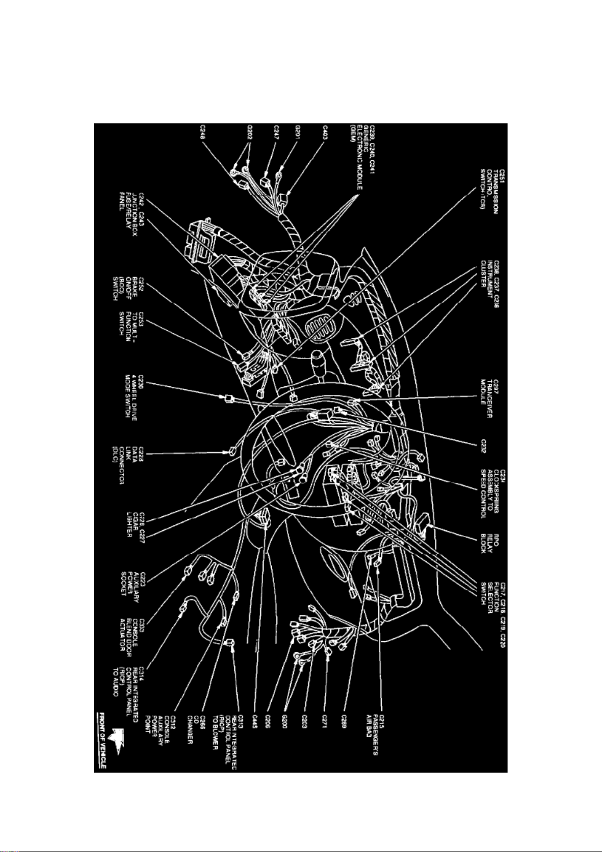
Accessory Delay Relay: Locations
Instrument Panel View
Page 6
Ford Expedition 2wd Workshop Manual (V8-281 4.6L VIN W EFI (1997))
Ford Workshop Manuals > Relays and Modules > Relays and Modules - Accessories and Optional Equipment > Accessory
Delay Module > Accessory Delay Relay > Component Information > Locations > Page 15
Page 7

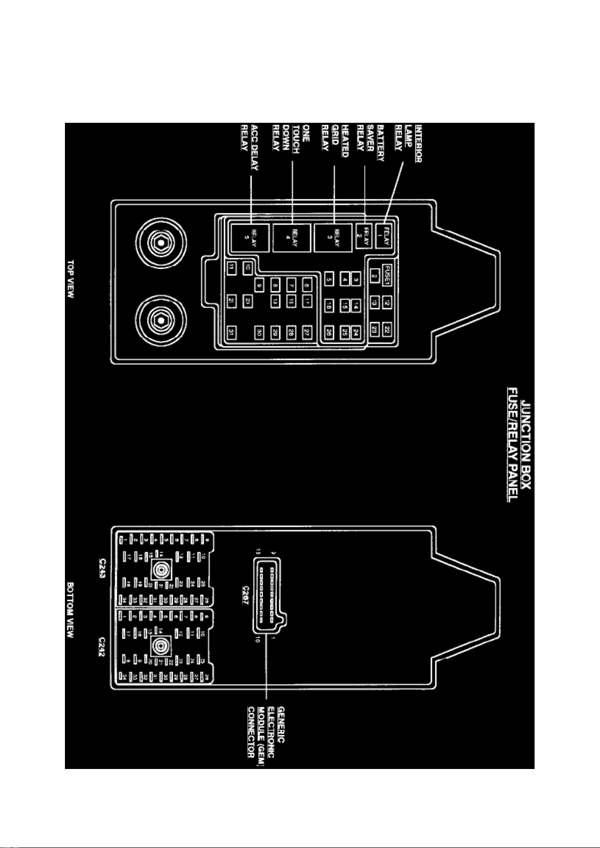
Junction Box Fuse/Relay Panel (Part 1 Of 2)
The Accessory Delay Relay is located in the junction box fuse/relay panel.
Page 8

Ford Expedition 2wd Workshop Manual (V8-281 4.6L VIN W EFI (1997))
Ford Workshop Manuals > Relays and Modules > Relays and Modules - Accessories and Optional Equipment > Alarm
Module, (Vehicle Antitheft) > Component Information > Specifications
Page 9

Alarm Module: Specifications
Passive Anti-Theft System Module Screws
............................................................................................................................... 4.5-6.3 Nm
(41-56.2 In Lb)
Page 10
Ford Expedition 2wd Workshop Manual (V8-281 4.6L VIN W EFI (1997))
Ford Workshop Manuals > Relays and Modules > Relays and Modules - Accessories and Optional Equipment > Alarm
Module, (Vehicle Antitheft) > Component Information > Locations > Anti-Theft Transceiver Module
Page 11

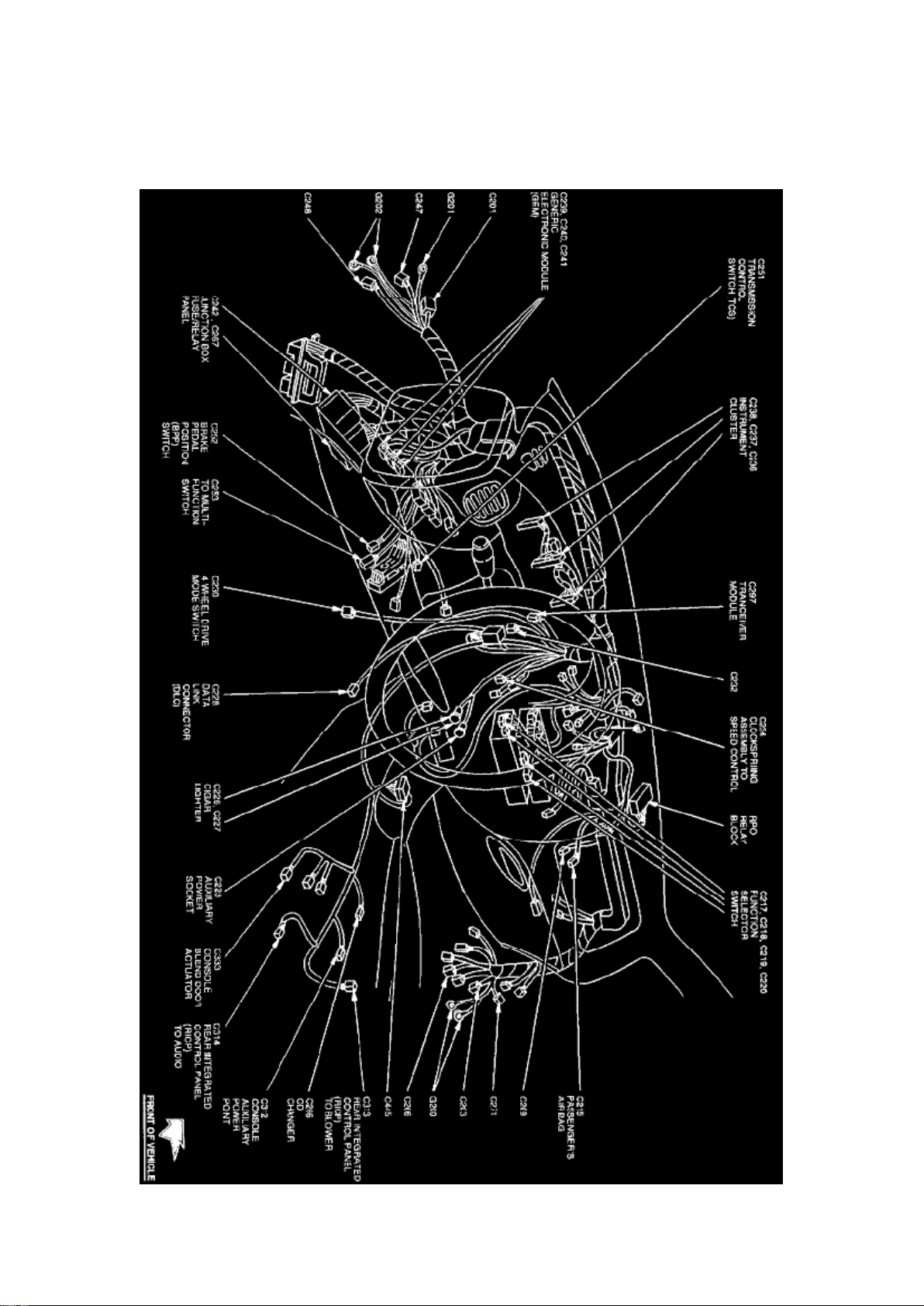
Alarm Module: Locations Anti-Theft Transceiver Module
Instrument Panel View
The Anti Theft-Transceiver Module is located behind the instrument panel.
Page 12
Ford Expedition 2wd Workshop Manual (V8-281 4.6L VIN W EFI (1997))
Ford Workshop Manuals > Relays and Modules > Relays and Modules - Accessories and Optional Equipment > Alarm
Module, (Vehicle Antitheft) > Component Information > Locations > Anti-Theft Transceiver Module > Page 21
Page 13

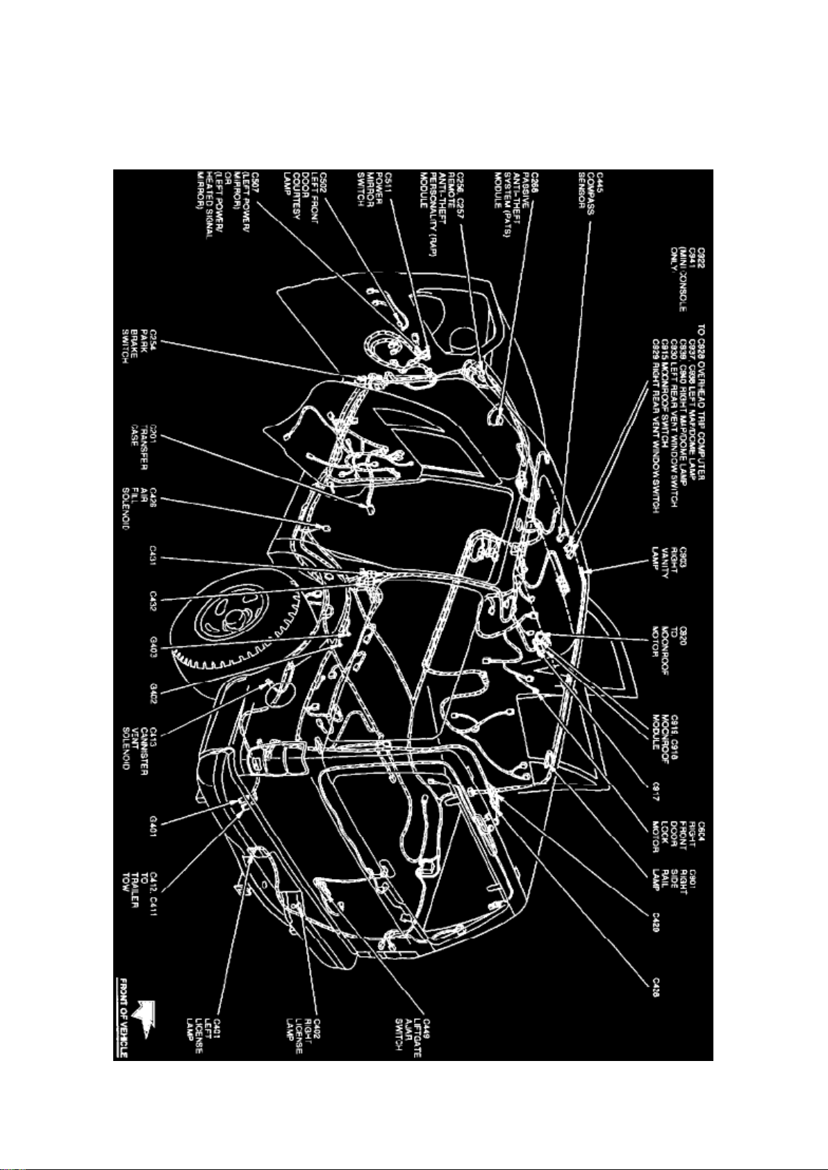
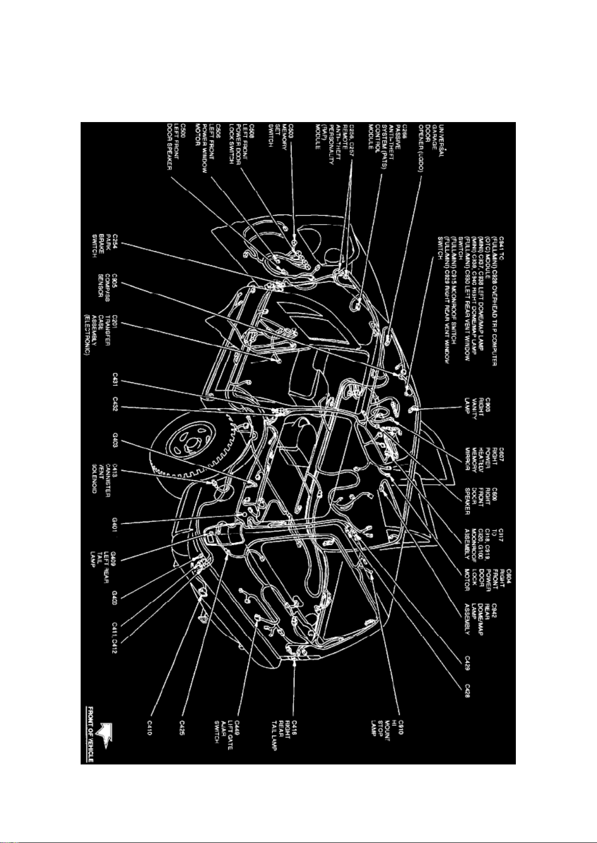
Alarm Module: Locations Passive Anti-Theft System Module
Body View
The Passive Anti-Theft System Module is located behind center of the instrument panel.
Page 14
Ford Expedition 2wd Workshop Manual (V8-281 4.6L VIN W EFI (1997))
Ford Workshop Manuals > Relays and Modules > Relays and Modules - Accessories and Optional Equipment > Alarm
Module, (Vehicle Antitheft) > Component Information > Locations > Anti-Theft Transceiver Module > Page 22
Page 15

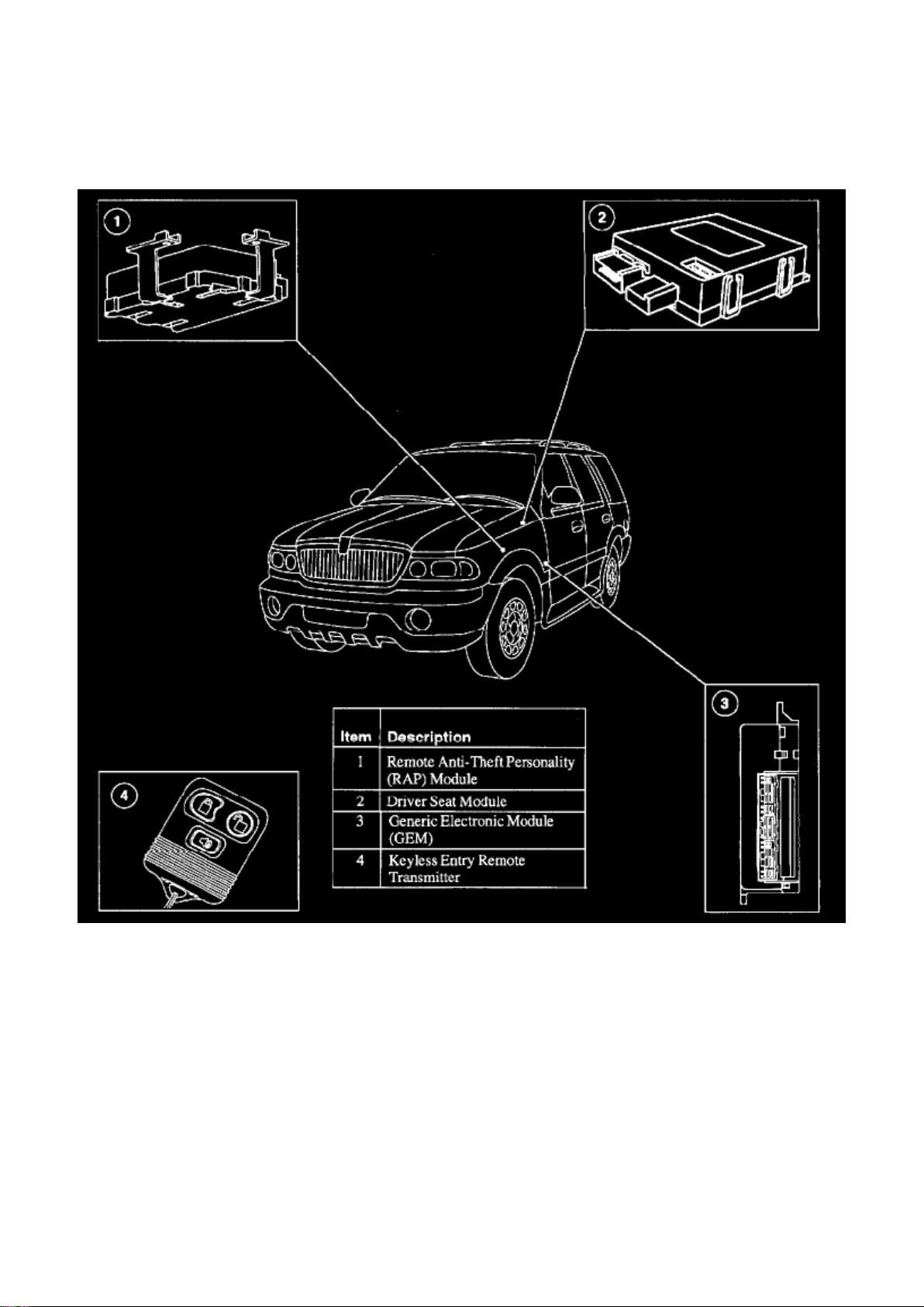
Alarm Module: Locations Remote Anti-Theft Personality Module
Body Views
Page 16
Ford Expedition 2wd Workshop Manual (V8-281 4.6L VIN W EFI (1997))
Ford Workshop Manuals > Relays and Modules > Relays and Modules - Accessories and Optional Equipment > Alarm
Module, (Vehicle Antitheft) > Component Information > Locations > Anti-Theft Transceiver Module > Page 23
The Remote Anti-Theft Personality Module is located behind left side of instrument panel.
Page 17
Ford Expedition 2wd Workshop Manual (V8-281 4.6L VIN W EFI (1997))
Ford Workshop Manuals > Relays and Modules > Relays and Modules - Accessories and Optional Equipment > Alarm
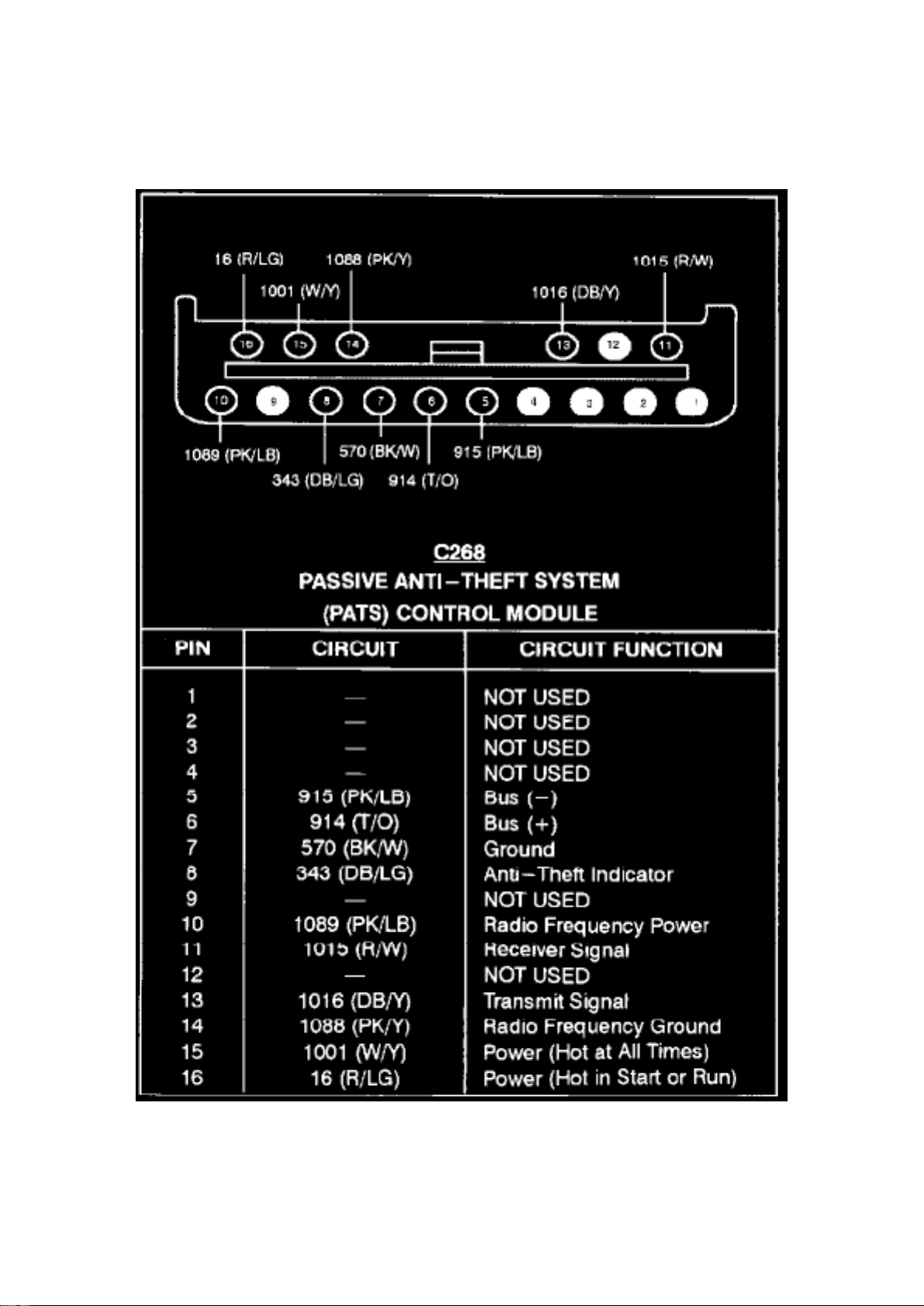
Module, (Vehicle Antitheft) > Component Information > Diagrams > Anti-Theft Controller Module
Passive Anti-Theft System Control Module
Page 18
Ford Expedition 2wd Workshop Manual (V8-281 4.6L VIN W EFI (1997))
Ford Workshop Manuals > Relays and Modules > Relays and Modules - Accessories and Optional Equipment > Alarm
Module, (Vehicle Antitheft) > Component Information > Diagrams > Anti-Theft Controller Module > Page 26
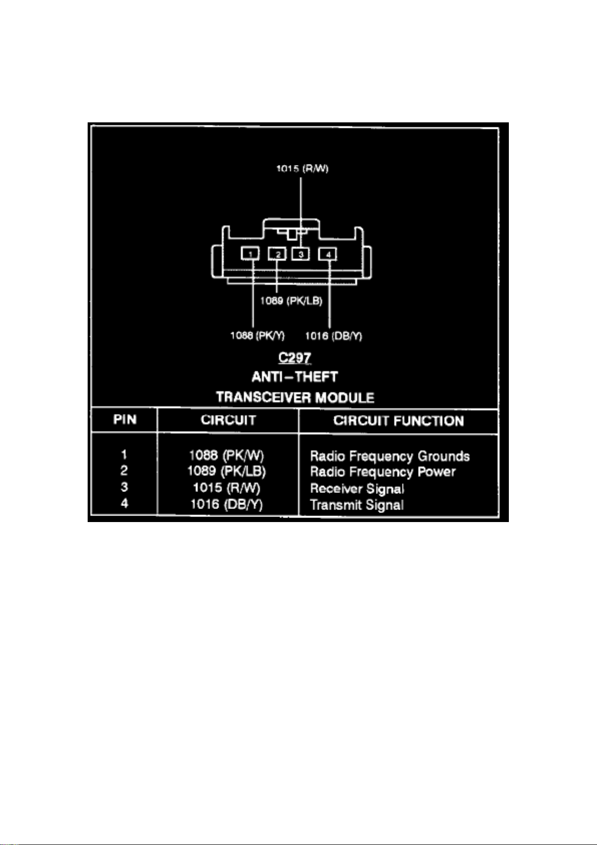
Anti-Theft Transceiver Module
Page 19
Ford Expedition 2wd Workshop Manual (V8-281 4.6L VIN W EFI (1997))
Ford Workshop Manuals > Relays and Modules > Relays and Modules - Accessories and Optional Equipment > Alarm
Module, (Vehicle Antitheft) > Component Information > Diagrams > Anti-Theft Controller Module > Page 27
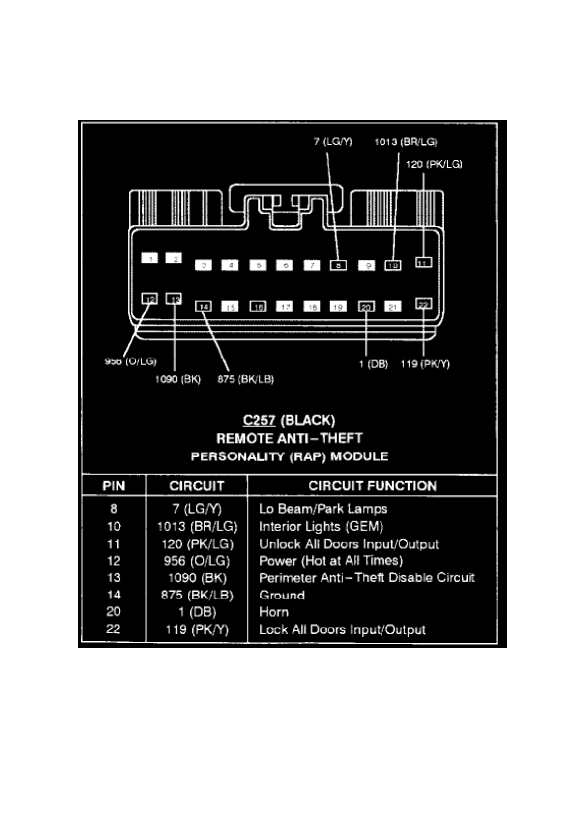
Alarm Module: Diagrams Remote Anti-Theft Personality Module
Remote Anti-Theft Personality Module (C257)
Page 20
Ford Expedition 2wd Workshop Manual (V8-281 4.6L VIN W EFI (1997))
Ford Workshop Manuals > Relays and Modules > Relays and Modules - Accessories and Optional Equipment > Alarm
Module, (Vehicle Antitheft) > Component Information > Diagrams > Anti-Theft Controller Module > Page 28
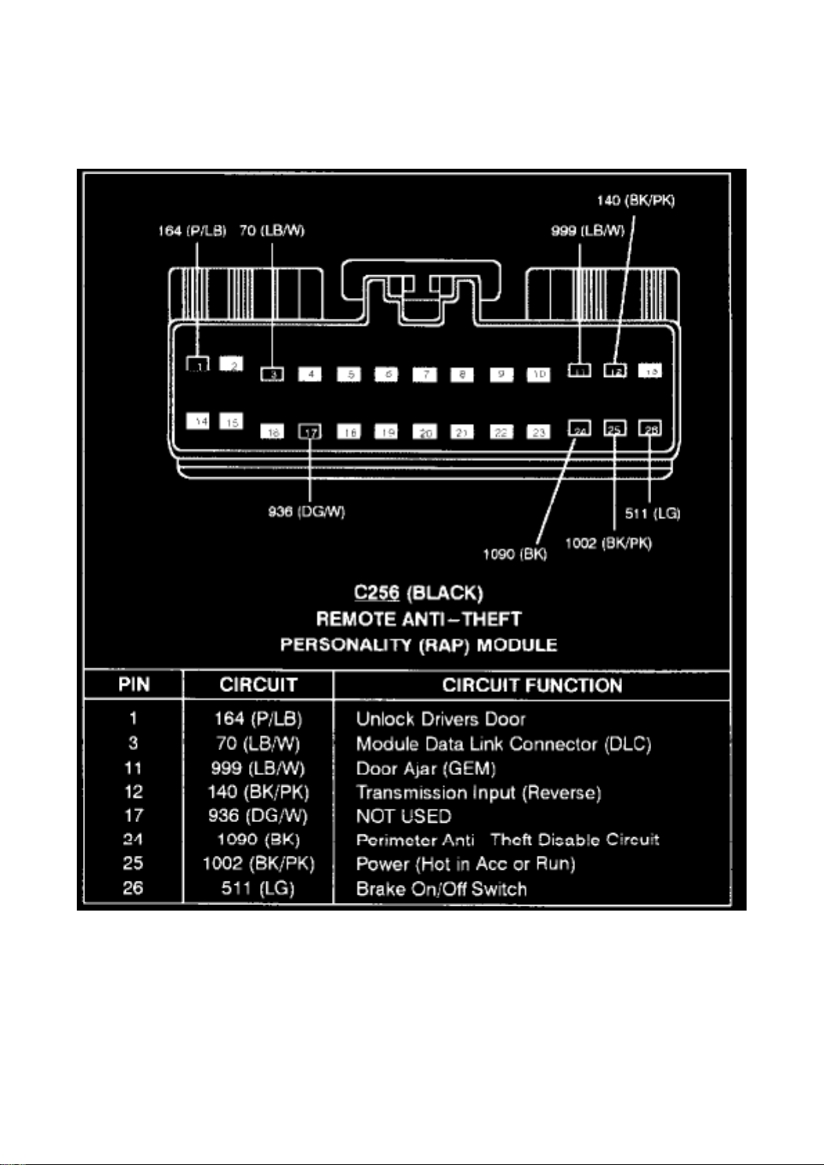
Remote Anti-Theft Personality Module (C256)
Page 21
Ford Expedition 2wd Workshop Manual (V8-281 4.6L VIN W EFI (1997))
Ford Workshop Manuals > Relays and Modules > Relays and Modules - Accessories and Optional Equipment > Alarm
Module, (Vehicle Antitheft) > Component Information > Diagrams > Page 29
Page 22

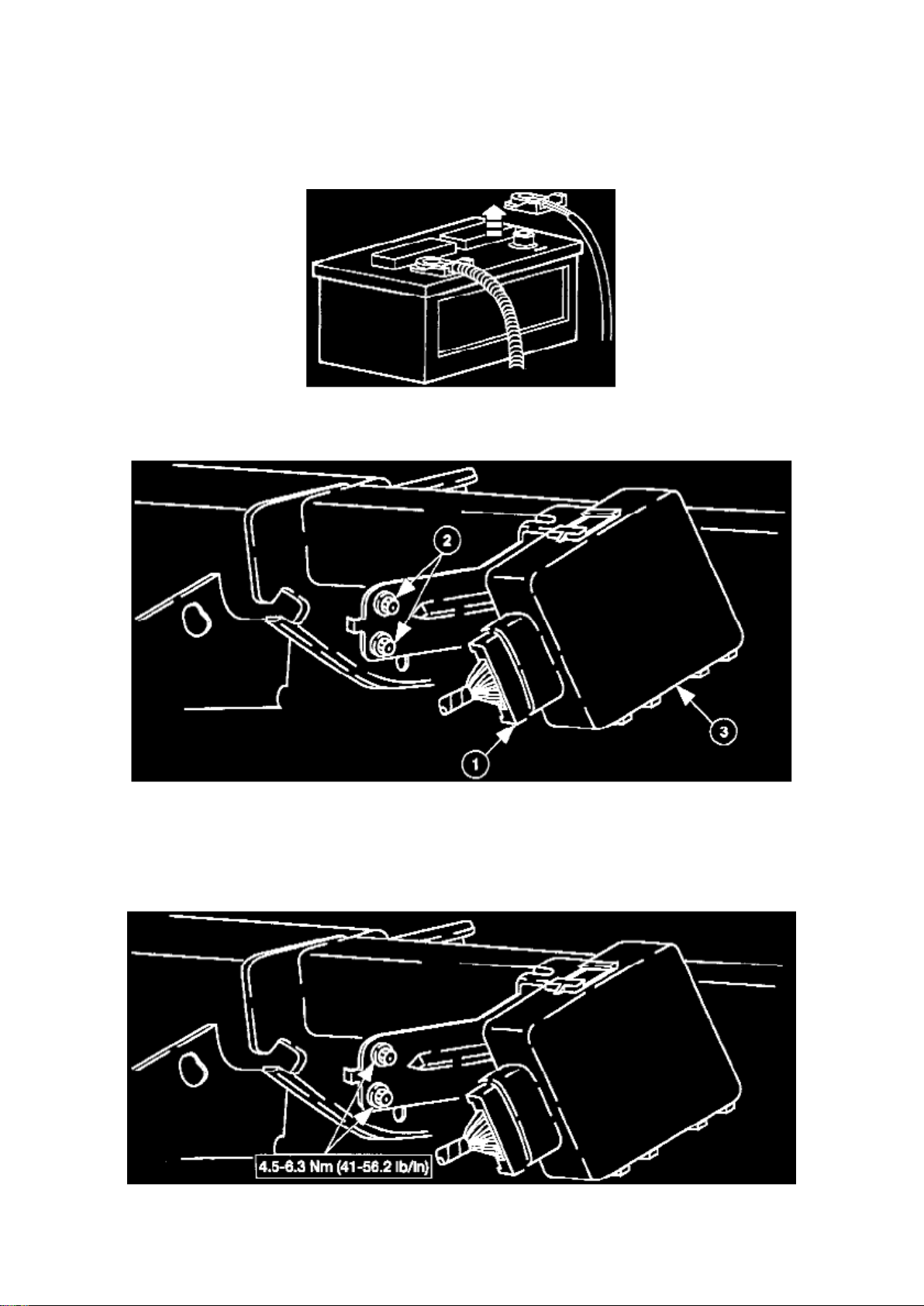
Alarm Module: Service and Repair
REMOVAL
1. Disconnect the battery ground cable. 2. Remove the PATS module.
1. Disconnect the electrical connector. 2. Remove the two screws. 3. Remove the PATS module.
INSTALLATION
1. To install, reverse the removal procedure.
NOTE: When the battery is disconnected and reconnected, some abnormal drive symptoms may
occur while the vehicle relearns its adaptive strategy. The vehicle may need to be driven 16 km (10
mi) or more to relearn the strategy.
Page 23

Ford Expedition 2wd Workshop Manual (V8-281 4.6L VIN W EFI (1997))
Ford Workshop Manuals > Relays and Modules > Relays and Modules - Accessories and Optional Equipment >
Multifunction Electronic Control Module <--> [General Module] > Component Information > Specifications
Page 24

Multifunction Electronic Control Module: Specifications
GEM Screws ........................................................................................................................................
.......................................... 0.9-1.3 Nm (8-12 In Lb)
Page 25
Ford Expedition 2wd Workshop Manual (V8-281 4.6L VIN W EFI (1997))
Ford Workshop Manuals > Relays and Modules > Relays and Modules - Accessories and Optional Equipment >
Multifunction Electronic Control Module <--> [General Module] > Component Information > Specifications > Page 33
Page 26

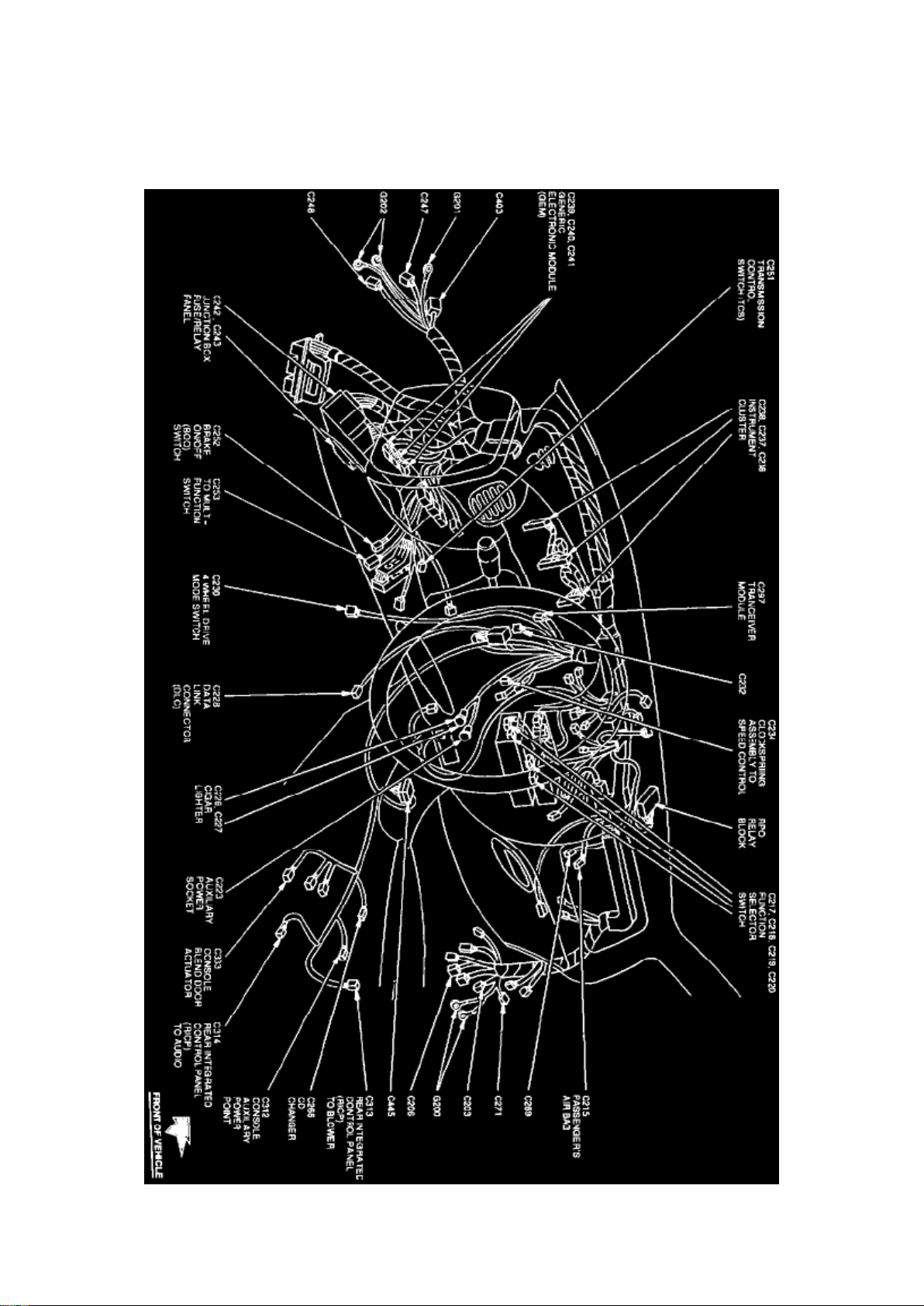
Multifunction Electronic Control Module: Locations
Instrument Panel View
The Generic Electronic Module is located behind center of the instrument panel.
Page 27
Ford Expedition 2wd Workshop Manual (V8-281 4.6L VIN W EFI (1997))
Ford Workshop Manuals > Relays and Modules > Relays and Modules - Accessories and Optional Equipment >
Multifunction Electronic Control Module <--> [General Module] > Component Information > Diagrams > Diagram Information
and Instructions
Multifunction Electronic Control Module: Diagram Information and Instructions
How to Find and Use These Diagrams
Diagrams are presented in three main categories:
- Power Distribution Diagrams
- System Diagrams
- Grounds Diagrams
Page 28

Ford Expedition 2wd Workshop Manual (V8-281 4.6L VIN W EFI (1997))
Ford Workshop Manuals > Relays and Modules > Relays and Modules - Accessories and Optional Equipment >
Multifunction Electronic Control Module <--> [General Module] > Component Information > Diagrams > Diagram Information
and Instructions > Page 36
Page 29
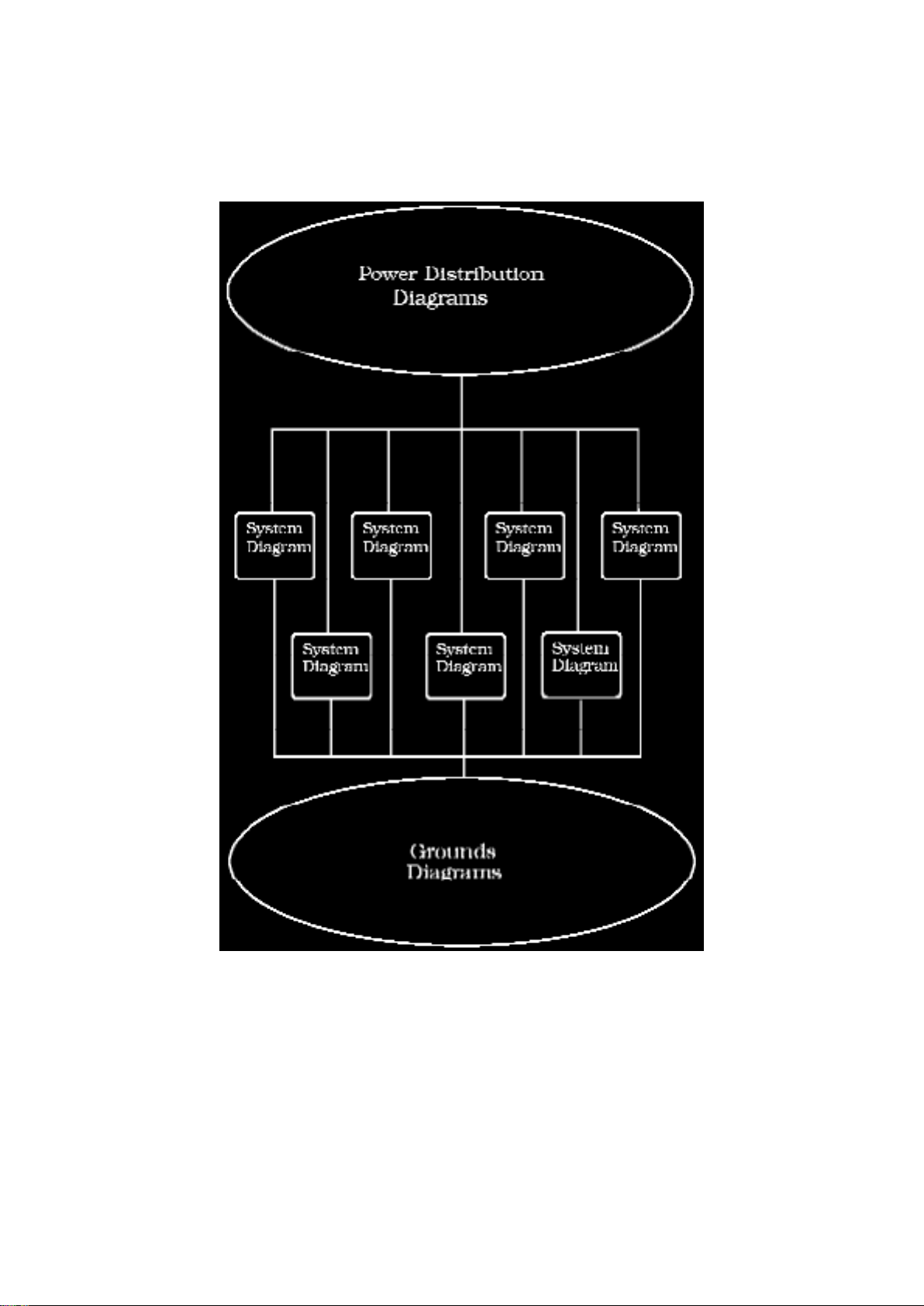
Sample Power Distribution Diagram
Page 30

Power Distribution Diagrams Provide the circuit details of how the system diagrams are powered.
The power distribution source is shown at the top of a diagram page. All wires, connectors, and
splices are shown in the same manner that the current flows, ending at the component/system
being powered near the bottom of a diagram page. Circuits that go from one diagram page to
another will be marked with large arrow heads.
The power distribution diagrams can be found at Starting and Charging/Power and Ground
Distribution.
Page 31

Ford Expedition 2wd Workshop Manual (V8-281 4.6L VIN W EFI (1997))
Ford Workshop Manuals > Relays and Modules > Relays and Modules - Accessories and Optional Equipment >
Multifunction Electronic Control Module <--> [General Module] > Component Information > Diagrams > Diagram Information
and Instructions > Page 37
Page 32
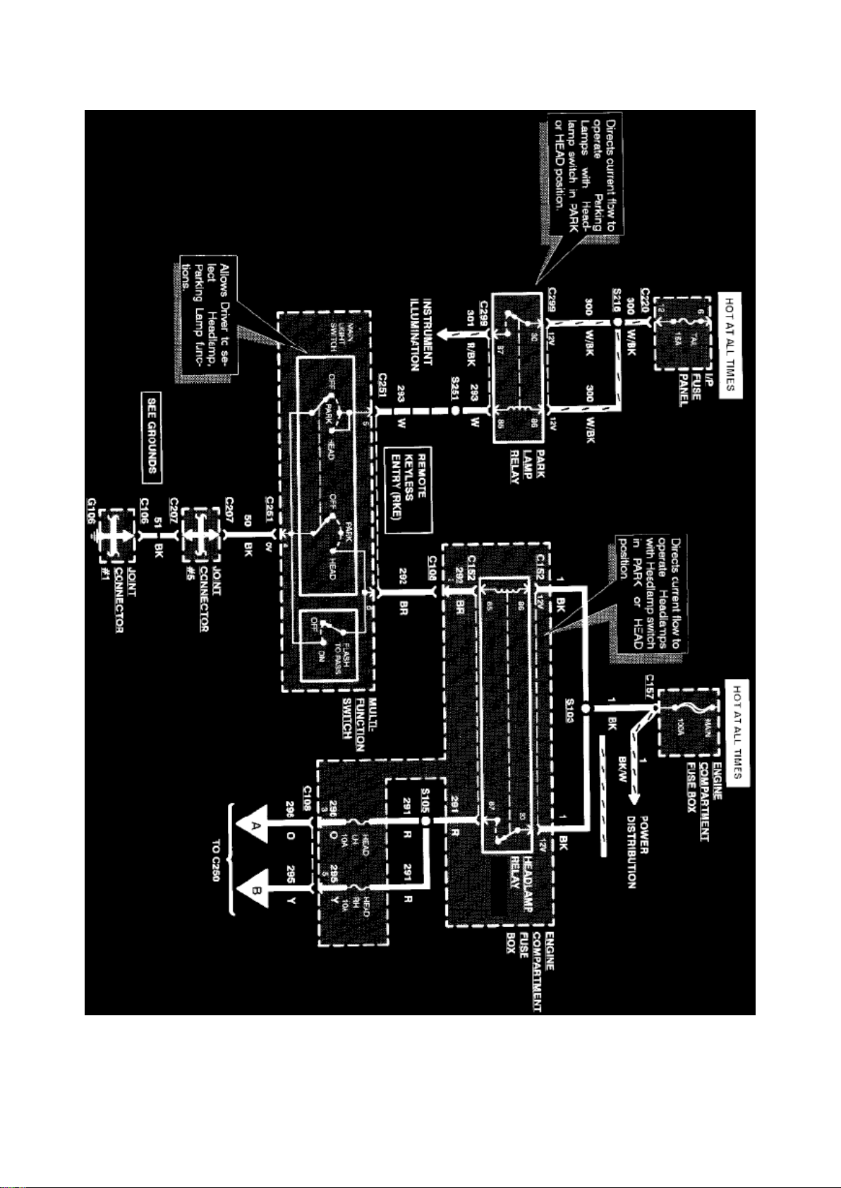
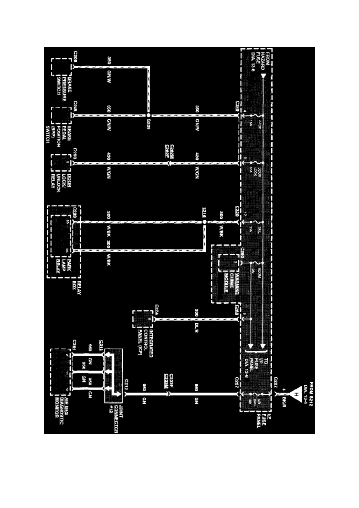
Sample System Diagram
Page 33

System Diagrams Components that work together are shown together in a system/subsystem
diagram or set of diagrams. The system feed (circuit breaker, fuse, etc.) is shown at the top of a
diagram page. All wires, connectors, components, and splices are shown in the same manner that
the current flows, ending at the ground at the bottom of a diagram page. Circuits that go from one
diagram page to another will be marked with large arrow heads.
Page 34

Ford Expedition 2wd Workshop Manual (V8-281 4.6L VIN W EFI (1997))
Ford Workshop Manuals > Relays and Modules > Relays and Modules - Accessories and Optional Equipment >
Multifunction Electronic Control Module <--> [General Module] > Component Information > Diagrams > Diagram Information
and Instructions > Page 38
Page 35
Management, Radio/Stereo, etc.
Page 36

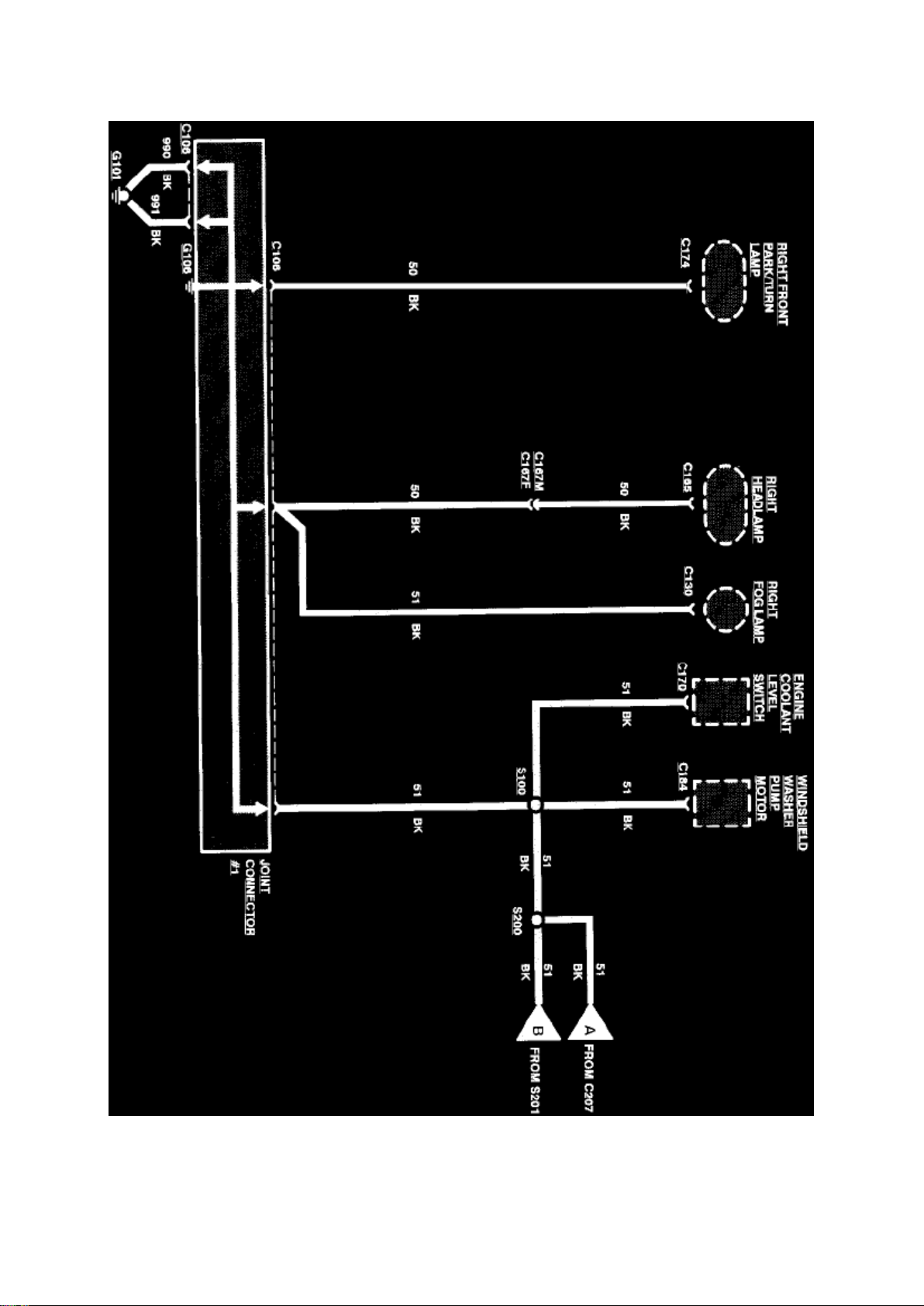
Sample Grounds Diagram
Grounds Diagrams Provide the circuit details of how the system diagrams are grounded. This
information is useful for checking interconnections of the grounding circuits of different systems.
The components/systems being grounded are shown at the top of a diagram page. All wires,
connectors, and splices are shown in the same manner that the current flows, ending at the ground
at the bottom of a diagram page. Circuits that go from one diagram page to another will be marked
with large arrow heads.
The grounds diagrams can be found at Starting and Charging/Power and Ground Distribution.
Symbol Identification
Page 37

Ford Expedition 2wd Workshop Manual (V8-281 4.6L VIN W EFI (1997))
Ford Workshop Manuals > Relays and Modules > Relays and Modules - Accessories and Optional Equipment >
Multifunction Electronic Control Module <--> [General Module] > Component Information > Diagrams > Diagram Information
and Instructions > Page 39
Page 38
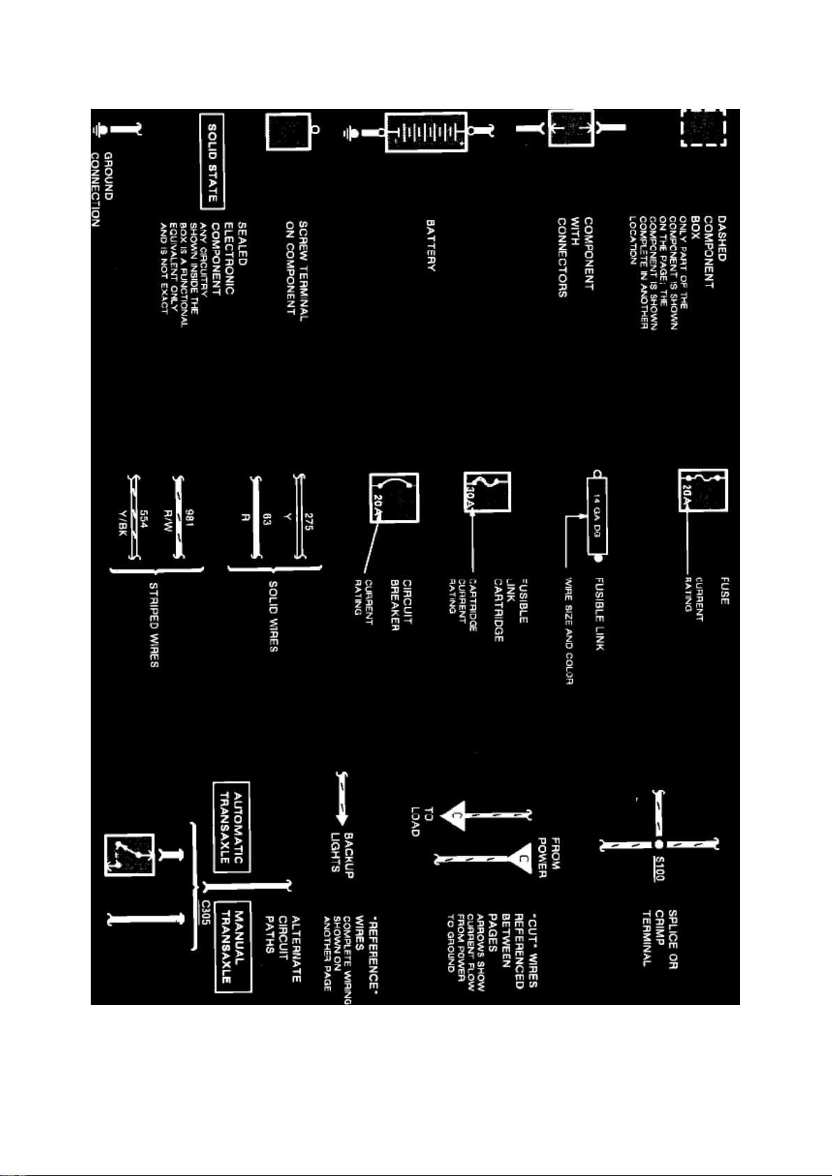
ELECTRICAL SYMBOLS
Page 39

Electrical Symbols
Page 40

Ford Expedition 2wd Workshop Manual (V8-281 4.6L VIN W EFI (1997))
Ford Workshop Manuals > Relays and Modules > Relays and Modules - Accessories and Optional Equipment >
Multifunction Electronic Control Module <--> [General Module] > Component Information > Diagrams > Diagram Information
and Instructions > Page 40
Page 41
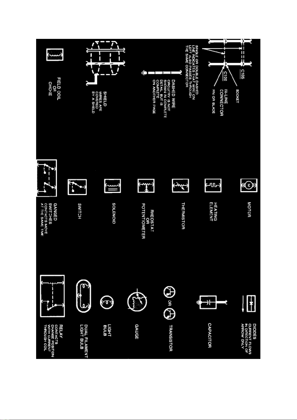
Electrical Symbols
Page 42

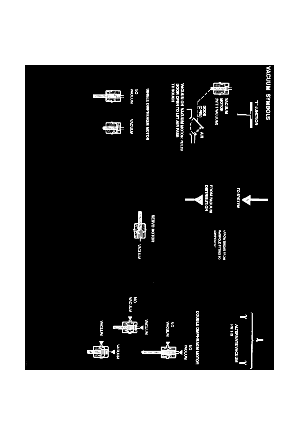
VACUUM SYMBOLS
Page 43
Ford Expedition 2wd Workshop Manual (V8-281 4.6L VIN W EFI (1997))
Ford Workshop Manuals > Relays and Modules > Relays and Modules - Accessories and Optional Equipment >
Multifunction Electronic Control Module <--> [General Module] > Component Information > Diagrams > Diagram Information
and Instructions > Page 41
Page 44

Symbol Identification/Vacuum Symbols
Wire Color Code Identification
BK: Black BL: Blue BR: Brown DB: Dark Blue DG: Dark Green GY: Gray GN: Green LB: Light Blue
Page 45

Ford Expedition 2wd Workshop Manual (V8-281 4.6L VIN W EFI (1997))
Ford Workshop Manuals > Relays and Modules > Relays and Modules - Accessories and Optional Equipment >
Multifunction Electronic Control Module <--> [General Module] > Component Information > Diagrams > Diagram Information
and Instructions > Page 42
Page 46

LG: Light Green PK: Pink O: Orange P: Purple R: Red T: Tan V: Violet W: White Y: Yellow
Page 47

NOTE: Whenever a wire is labeled with two colors, the first color listed is the basic color of the
wire, and the second color listed is the stripe marking of the wire.
Page 48

Ford Expedition 2wd Workshop Manual (V8-281 4.6L VIN W EFI (1997))
Ford Workshop Manuals > Relays and Modules > Relays and Modules - Accessories and Optional Equipment >
Multifunction Electronic Control Module <--> [General Module] > Component Information > Diagrams > Diagram Information
and Instructions > Page 43
Page 49
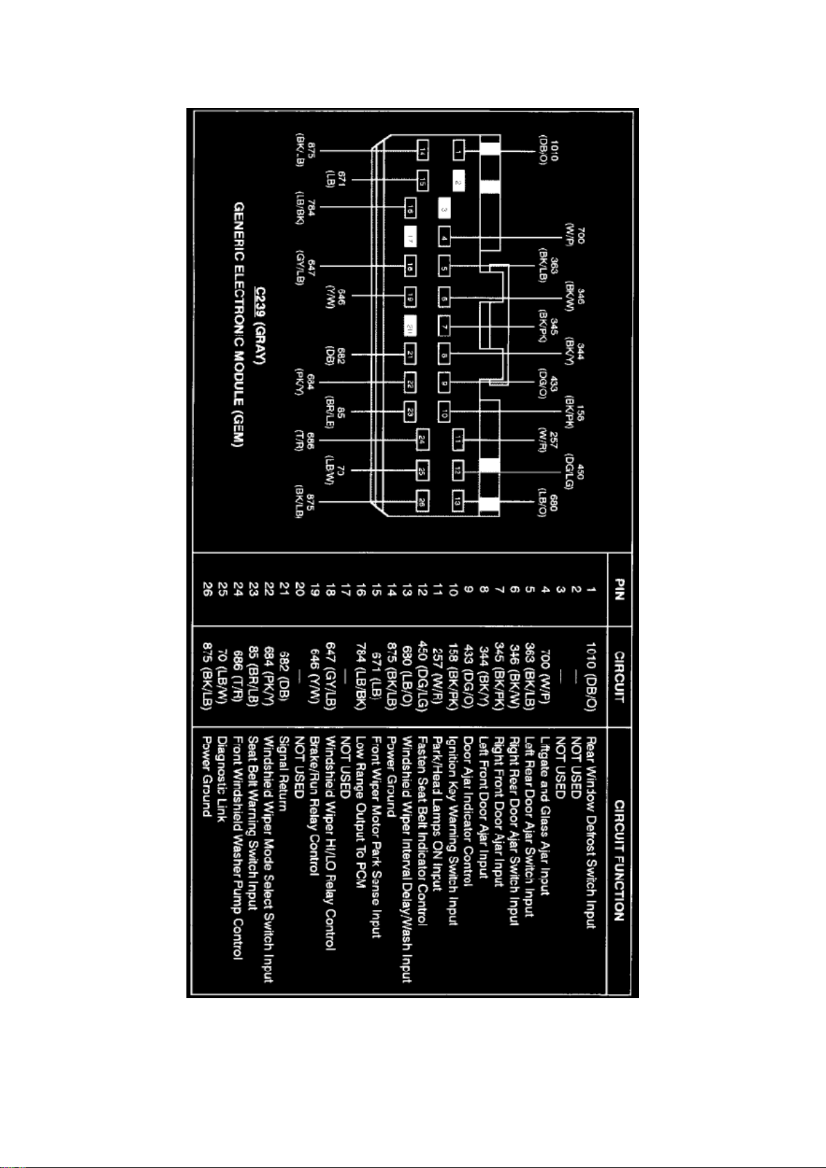
Multifunction Electronic Control Module: Connector Views
Page 50

Generic Electronic Module (C239)
Page 51

Ford Expedition 2wd Workshop Manual (V8-281 4.6L VIN W EFI (1997))
Ford Workshop Manuals > Relays and Modules > Relays and Modules - Accessories and Optional Equipment >
Multifunction Electronic Control Module <--> [General Module] > Component Information > Diagrams > Diagram Information
and Instructions > Page 44
Page 52
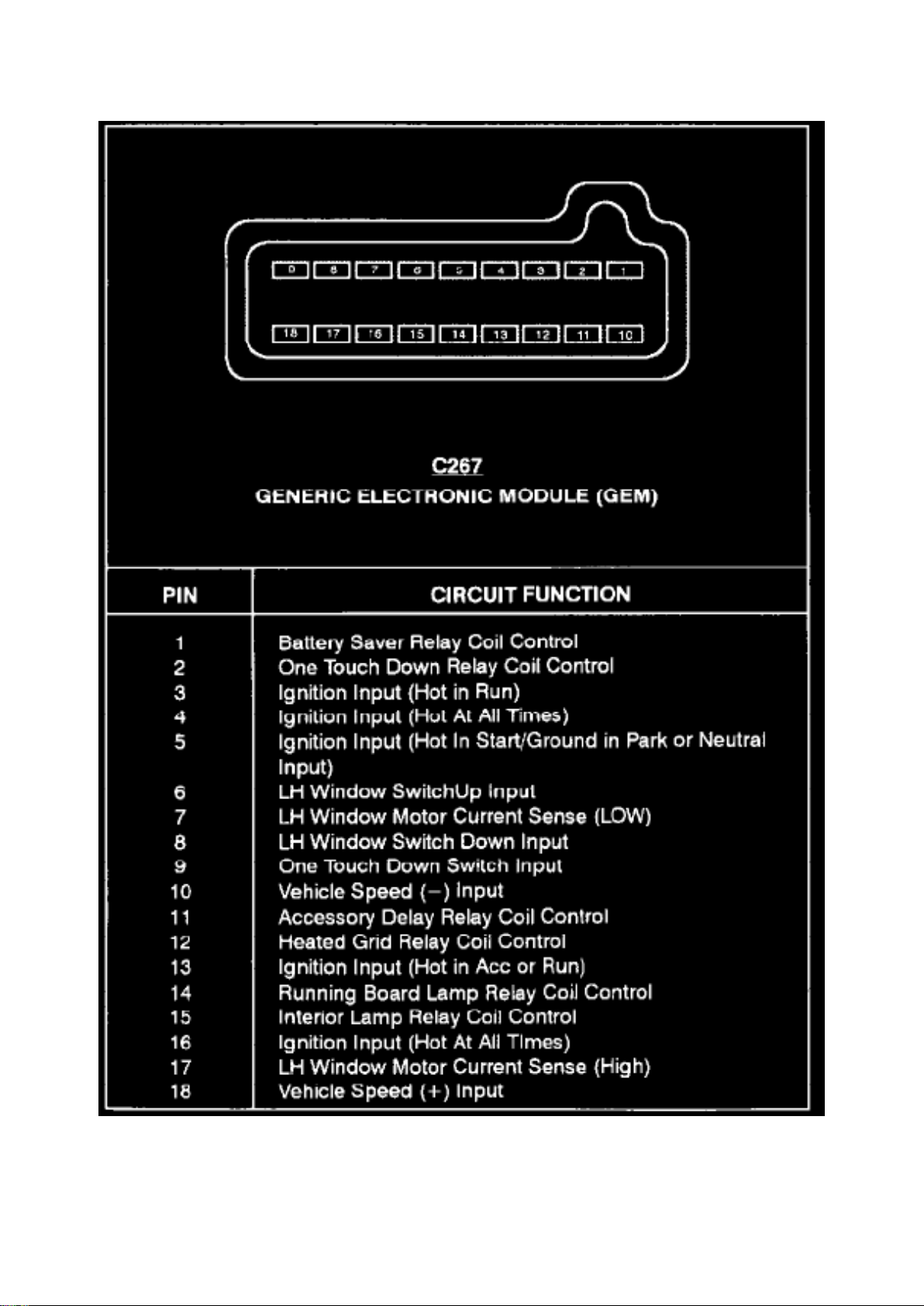
Generic Electronic Module (C267)
Page 53

Ford Expedition 2wd Workshop Manual (V8-281 4.6L VIN W EFI (1997))
Ford Workshop Manuals > Relays and Modules > Relays and Modules - Accessories and Optional Equipment >
Multifunction Electronic Control Module <--> [General Module] > Component Information > Diagrams > Diagram Information
and Instructions > Page 45
Page 54
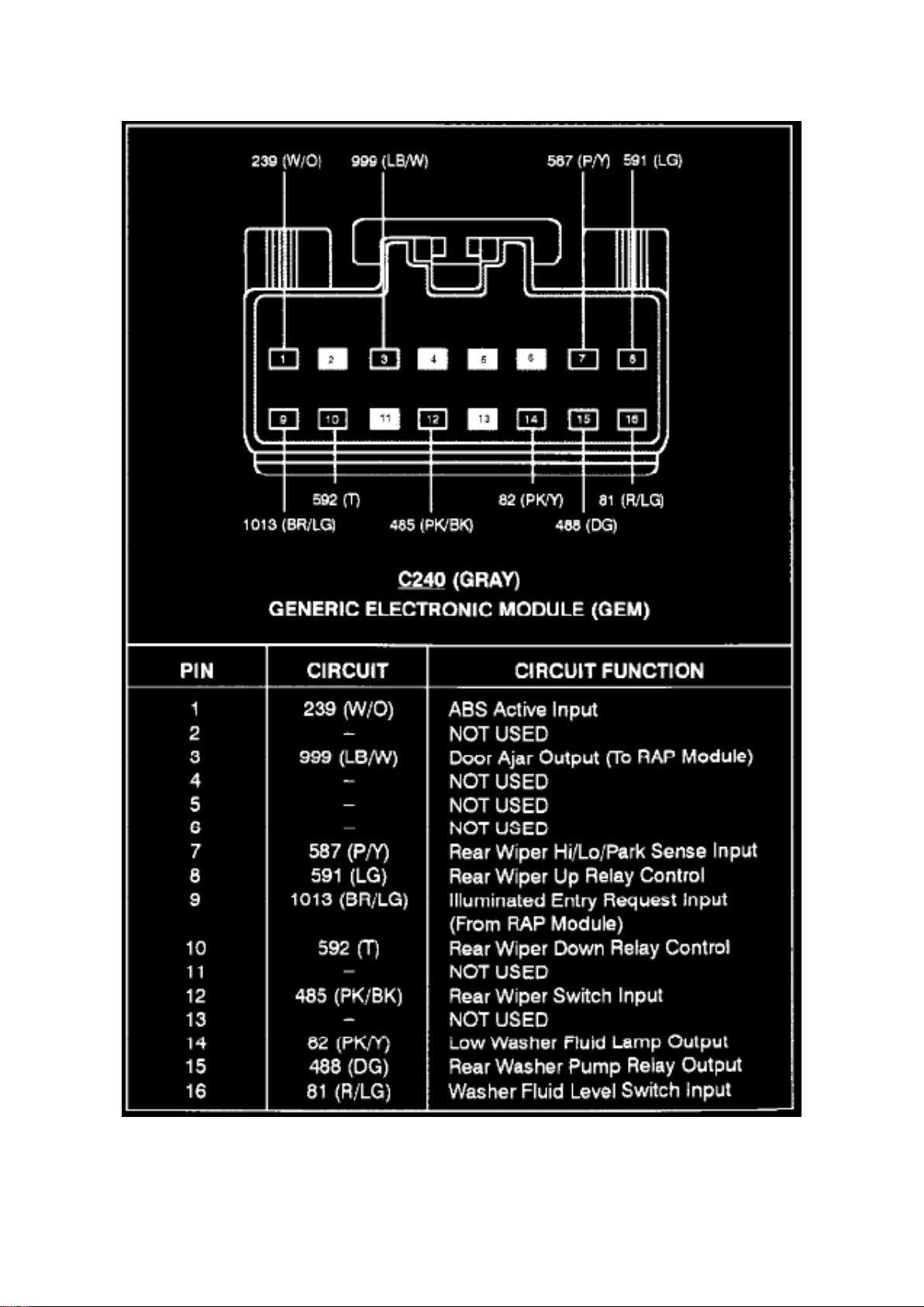
Generic Electronic Module (C240 )
Page 55

Ford Expedition 2wd Workshop Manual (V8-281 4.6L VIN W EFI (1997))
Ford Workshop Manuals > Relays and Modules > Relays and Modules - Accessories and Optional Equipment >
Multifunction Electronic Control Module <--> [General Module] > Component Information > Diagrams > Diagram Information
and Instructions > Page 46
Page 56
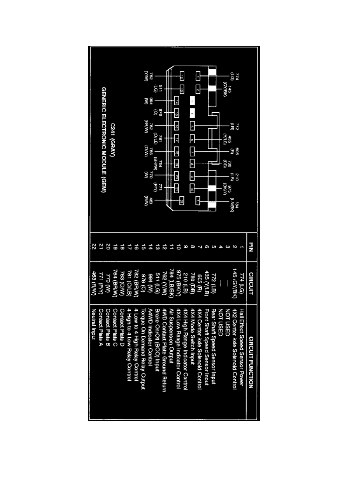
Generic Electronic Module (C241)
Page 57

Ford Expedition 2wd Workshop Manual (V8-281 4.6L VIN W EFI (1997))
Ford Workshop Manuals > Relays and Modules > Relays and Modules - Accessories and Optional Equipment >
Multifunction Electronic Control Module <--> [General Module] > Component Information > Diagrams > Diagram Information
and Instructions > Page 47
Page 58
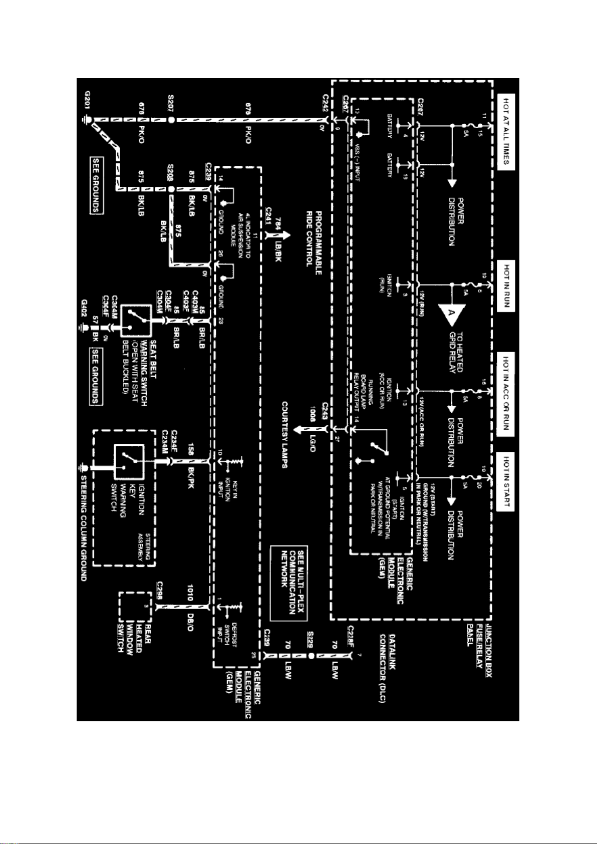
Multifunction Electronic Control Module: Electrical Diagrams
Page 59

Generic Electronic Module (Part 1 Of 5)
Page 60

Ford Expedition 2wd Workshop Manual (V8-281 4.6L VIN W EFI (1997))
Ford Workshop Manuals > Relays and Modules > Relays and Modules - Accessories and Optional Equipment >
Multifunction Electronic Control Module <--> [General Module] > Component Information > Diagrams > Diagram Information
and Instructions > Page 48
Page 61
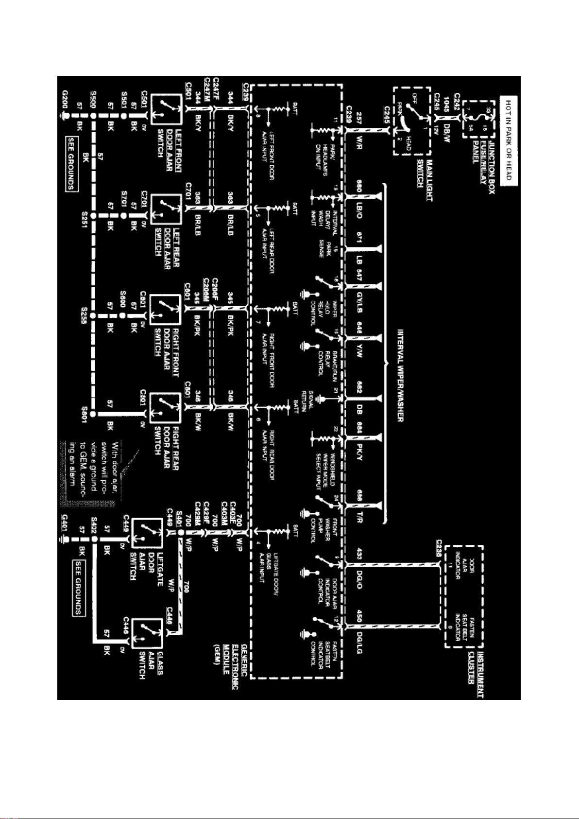
Generic Electronic Module (Part 2 Of 5)
Page 62

Ford Expedition 2wd Workshop Manual (V8-281 4.6L VIN W EFI (1997))
Ford Workshop Manuals > Relays and Modules > Relays and Modules - Accessories and Optional Equipment >
Multifunction Electronic Control Module <--> [General Module] > Component Information > Diagrams > Diagram Information
and Instructions > Page 49
Page 63
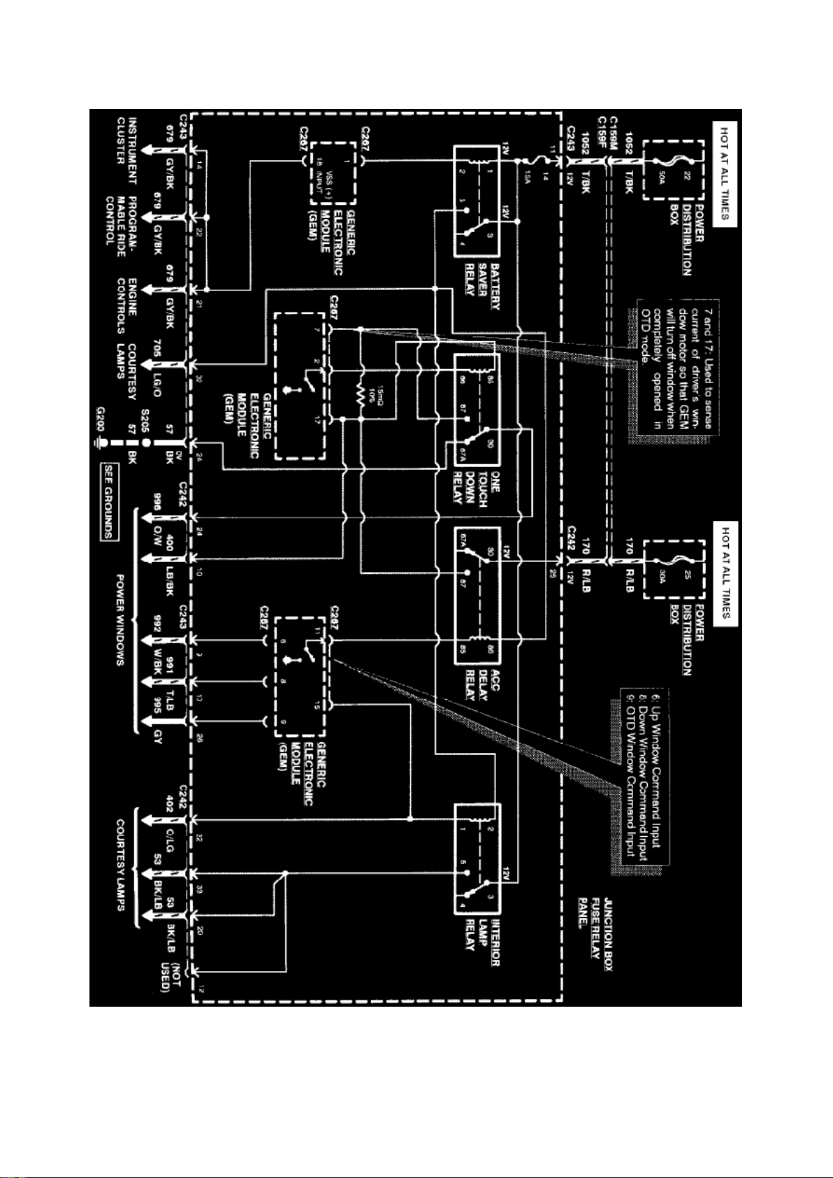
Generic Electronic Module (Part 3 Of 5)
Page 64

Ford Expedition 2wd Workshop Manual (V8-281 4.6L VIN W EFI (1997))
Ford Workshop Manuals > Relays and Modules > Relays and Modules - Accessories and Optional Equipment >
Multifunction Electronic Control Module <--> [General Module] > Component Information > Diagrams > Diagram Information
and Instructions > Page 50
Page 65
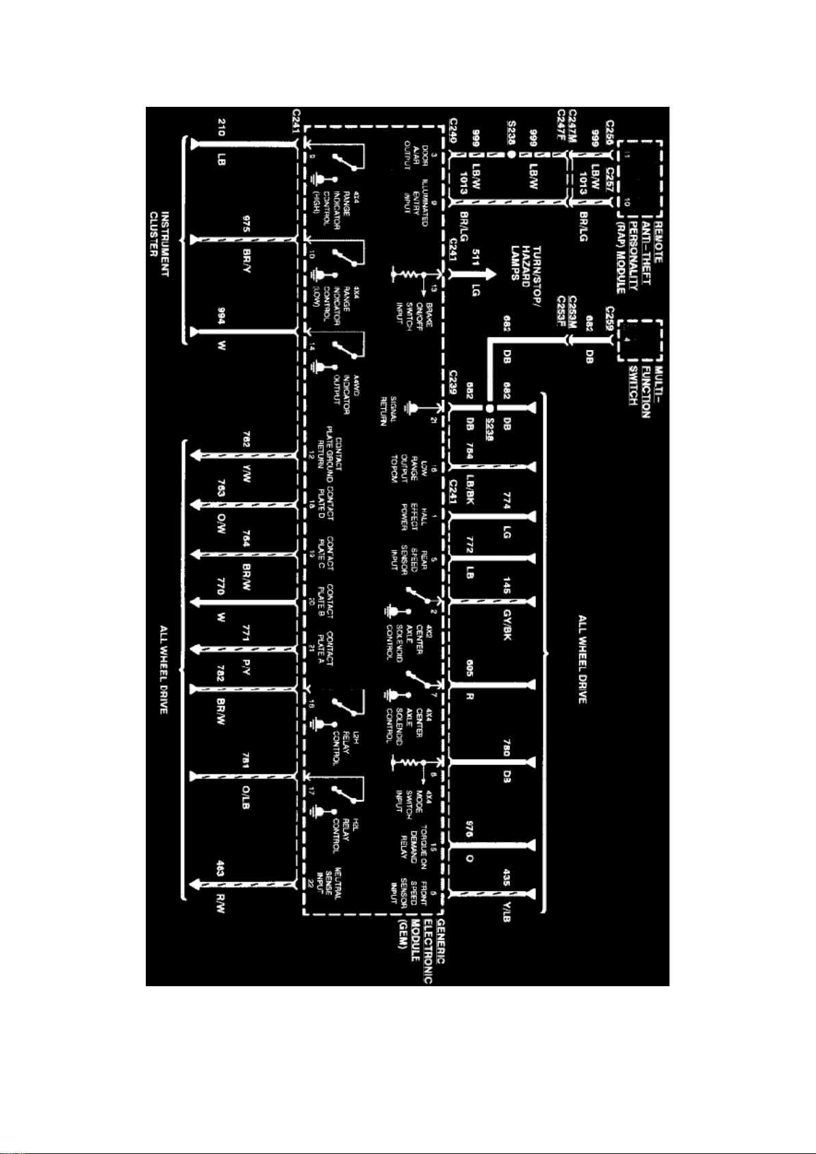
Generic Electronic Module (Part 4 Of 5)
Page 66

Ford Expedition 2wd Workshop Manual (V8-281 4.6L VIN W EFI (1997))
Ford Workshop Manuals > Relays and Modules > Relays and Modules - Accessories and Optional Equipment >
Multifunction Electronic Control Module <--> [General Module] > Component Information > Diagrams > Diagram Information
and Instructions > Page 51
Page 67
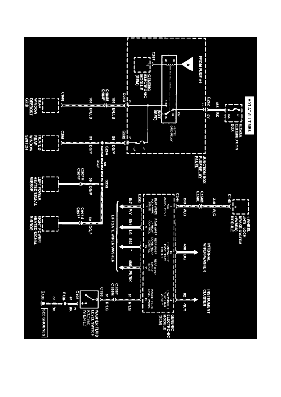
Generic Electronic Module (Part 5 Of 5)
Page 68
Ford Expedition 2wd Workshop Manual (V8-281 4.6L VIN W EFI (1997))
Ford Workshop Manuals > Relays and Modules > Relays and Modules - Accessories and Optional Equipment >
Multifunction Electronic Control Module <--> [General Module] > Component Information > Diagrams > Page 52
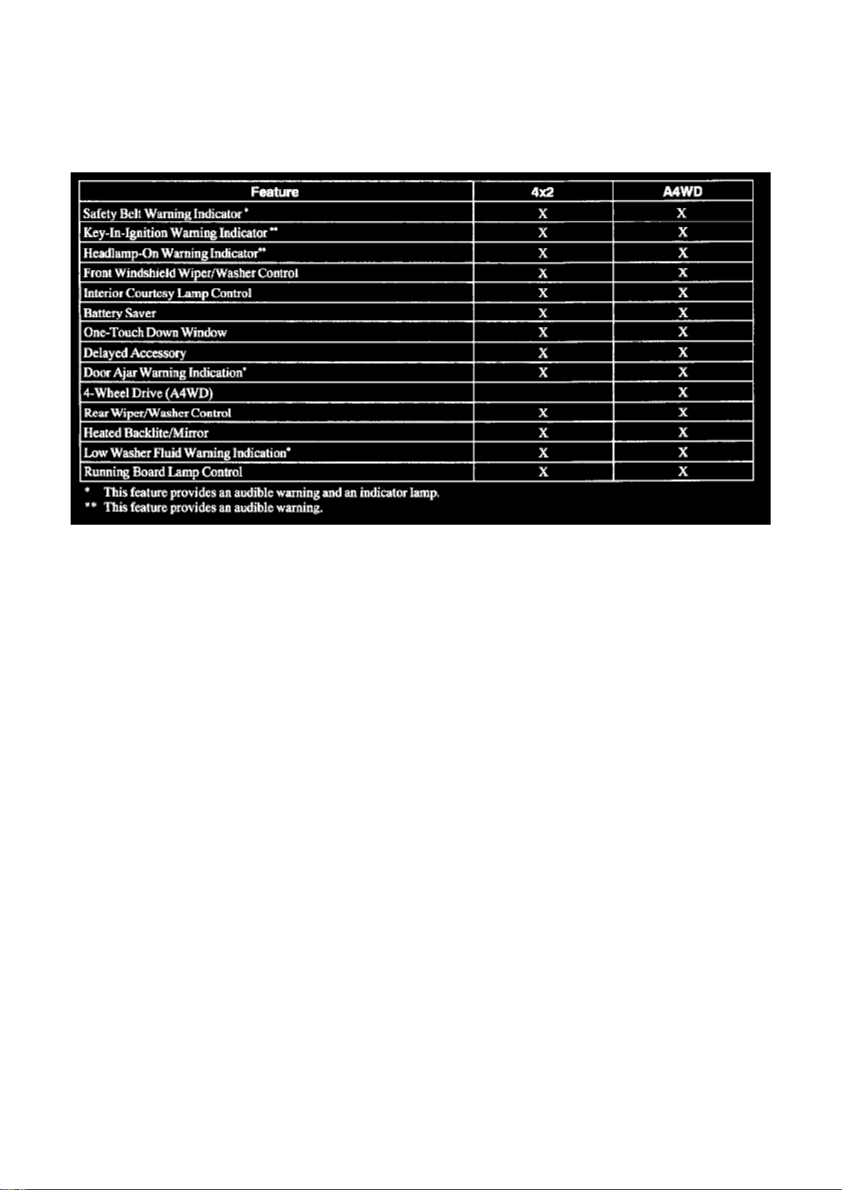
Multifunction Electronic Control Module: Description and Operation
GEM Circuit Protection
Short Circuit/Battery Voltage
The Generic Electronic Module (GEM) outputs are designed to withstand continuous exposure to a
short circuit to ground or battery voltage without being damaged.
GEM Feature and Functions
The GEM controls the following features: ^
Wipers/washers (front/rear).
^ Warning chimes.
^ Battery saver.
^ Illuminated entry and courtesy lamps.
^ Driver power window.
^ Accessory delay.
^ 4-wheel drive.
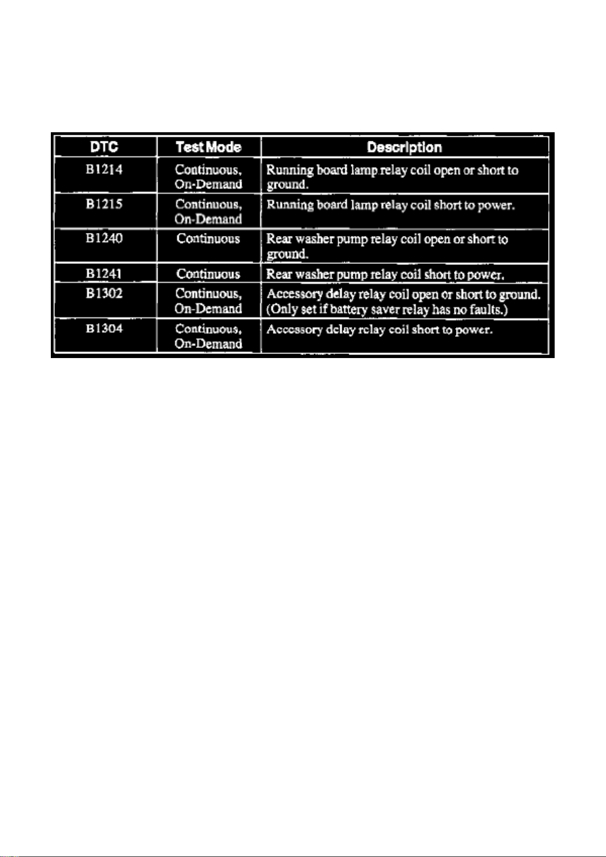
GEM Diagnostics
The Generic Electronic Module (GEM) diagnostics are accessible with the New Generation STAR
(NGS) tester and the Service Bay Diagnostic System (SBDS). The GEM constantly monitors its
subsystems for concerns. If a concern is found in one of the subsystems, the GEM will record the
concern in the form of a Diagnostic Trouble Code (DTC).
Page 69

There are three areas of diagnostic information useful when diagnosing the GEM. ^
DTCs - A record of past or present system problems.
^ PIDs - the present state of an input or output.
^ Active Commands - Gives the ability to turn on GEM outputs without activating the inputs
normally associated with the function.
Ignition Switch Positions
The position of the ignition switch is very important to proper Generic Electronic Module (GEM)
operation. Often times, erratic or unexpected operation can be traced to problems on these GEM
inputs. The following is a brief description of five ignition switch positions.
Run
When the ignition switch is in this position, battery voltage should be present at the GEM RUN and
RUN/ACC input terminals.
Accessory (ACC)
When the ignition switch is in this position, battery voltage should be present at the GEM RUN/ACC
input terminal only.
Start
When the ignition switch is in this position, battery voltage should he present at the GEM
start/clutch depressed input.
Off and Lock
The GEM does not have an OFF or LOCK Switch State input. The GEM will assume the OFF or
LOCK position when there are no RUN,
Page 70

Ford Expedition 2wd Workshop Manual (V8-281 4.6L VIN W EFI (1997))
Ford Workshop Manuals > Relays and Modules > Relays and Modules - Accessories and Optional Equipment >
Multifunction Electronic Control Module <--> [General Module] > Component Information > Diagrams > Page 53
ACC, or START signals present.
Wiper/Washer Control and Interval Timer
Front Wipers
There are four modes of operation for the front wipers: speed dependent interval, slow, fast, and
wash. These modes are only active with the ignition switch in the RUN or ACC position. Speed
dependent wipers compensate for the extra moisture that accumulates on the windshield at higher
speeds. At higher speeds, the speed dependent feature shortens the delay between wipes when
using the variable interval wiper feature. Delays will automatically adjust at speeds between 16 and
105 kph (10 and 65 mph).
Rear Wiper
There are two modes of operation for the rear wipers, internal and wash. These modes are only
active with the ignition switch in the RUN or ACC positions and both the liftgate and liftgate glass
are closed.
Chime Warning
There are five warning chimes and lamps the Generic Electronic Module (GEM) controls:
Headlights operating without the ignition ON (chime only), door ajar (chime and lamp), key in the
ignition (chime only), driver seat belt warning (chime and lamp), and low washer fluid warning
(chime and lamp).
Battery Saver
The battery saver feature removes extended interior lamp power drains from the battery. The
Generic Electronic Module (GEM) will keep power available for all interior lights and under hood
lamp circuits for 40 minutes after the ignition switch is turned OFF. The battery saver timer is reset
by unlocking doors with remote entry key fob, activating a door ajar switch, or changing the ignition
to RUN or ACC position. If asleep, the GEM will wake-up when: ^
Any door becomes ajar or is closed.
^ The key is inserted or removed.
^ The ignition switch is turned to ACC or RUN.
^ The doors are unlocked with the remote entry key fob.
Courtesy Lamps/Illuminated Entry
The Generic Electronic Module (GEM) illuminates the interior courtesy lamps when any door is
ajar. The GEM also provides illuminated entry when the unlock button is used to unlock the vehicle.
All interior courtesy lamps are turned OFF when any of the following occurs: ^
Page 71

Twenty-five seconds have elapsed since the illuminated entry feature was activated and no door is
ajar.
^ The ignition switch is turned to RUN and no door is ajar.
^ Vehicle speed is over 15 mph (a new ajar signal will turn on courtesy lamps only if the vehicle
speed is less than 10 mph).
^ A power door lock command is received from the remote entry key fob and no door is ajar.
Running Board Lamps
The GEM illuminates the running board lamps when the interior lamps are activated and the
ignition switch is not in the RUN position.
Delayed Accessory (GEM only)
The delayed accessory feature provides power to the power windows for ten minutes after the
ignition switch is moved from the RUN to OFF position. If during this ten-minute period either front
door is opened, the delayed accessory relay will be de-energized.
One-Touch Window
The power switch for the driver window control has two detents for the down window control. With
the ignition switch in RUN or ACC, pressing the first detent (normal mode) allows manual down
window control; pressing harder to the second detent (auto) will cause the driver window to
automatically move to the full down position. Pressing either the up or down window switch will
cancel an auto mode operation in progress.
Page 72

Ford Expedition 2wd Workshop Manual (V8-281 4.6L VIN W EFI (1997))
Ford Workshop Manuals > Relays and Modules > Relays and Modules - Accessories and Optional Equipment >
Multifunction Electronic Control Module <--> [General Module] > Component Information > Testing and Inspection > Flow of
Diagnosis
Page 73

Multifunction Electronic Control Module: Flow of Diagnosis
Page 74

1. Verify the customer's concern by operating the system in question. 2. Visually inspect for
obvious signs of mechanical and electrical damage.
Mechanical ^
Switch(es).
Electrical ^
Fuse(s).
^ Circuit(s).
^ Damaged wiring harness(es).
^ Loose or damaged wires or connectors.
3. If the concern is not visually evident, determine the symptom and proceed to the Symptom
Chart. See: Symptom Related Diagnostic Procedures
Page 75

Ford Expedition 2wd Workshop Manual (V8-281 4.6L VIN W EFI (1997))
Ford Workshop Manuals > Relays and Modules > Relays and Modules - Accessories and Optional Equipment >
Multifunction Electronic Control Module <--> [General Module] > Component Information > Testing and Inspection > Flow of
Diagnosis > Page 56
Page 76

Multifunction Electronic Control Module: Initial Inspection and Diagnostic Overview
Page 77

1. Verify the customer's concern by operating the system in question. 2. Visually inspect for
obvious signs of mechanical and electrical damage.
Mechanical ^
Switch(es).
Electrical ^
Fuse(s).
^ Circuit(s).
^ Damaged wiring harness(es).
^ Loose or damaged wires or connectors.
3. If the concern is not visually evident, determine the symptom and proceed to the Symptom
Chart. See: Symptom Related Diagnostic Procedures
Page 78
Ford Expedition 2wd Workshop Manual (V8-281 4.6L VIN W EFI (1997))
Ford Workshop Manuals > Relays and Modules > Relays and Modules - Accessories and Optional Equipment >
Multifunction Electronic Control Module <--> [General Module] > Component Information > Testing and Inspection > Flow of
Diagnosis > Page 57
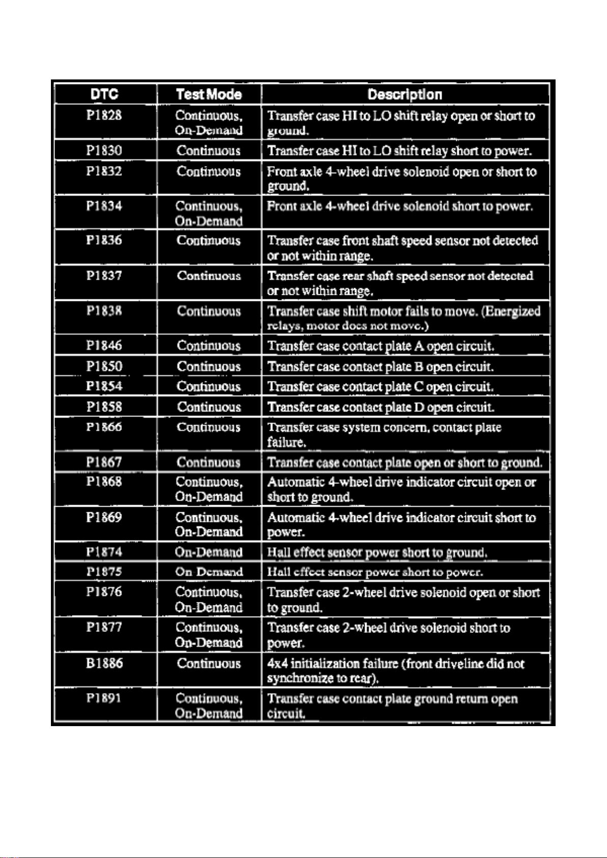
Multifunction Electronic Control Module: Diagnostic Trouble Code Descriptions
Part 1 Of 5
Page 79

Ford Expedition 2wd Workshop Manual (V8-281 4.6L VIN W EFI (1997))
Ford Workshop Manuals > Relays and Modules > Relays and Modules - Accessories and Optional Equipment >
Multifunction Electronic Control Module <--> [General Module] > Component Information > Testing and Inspection > Flow of
Diagnosis > Page 58
Page 80

Part 2 Of 5
Page 81

Ford Expedition 2wd Workshop Manual (V8-281 4.6L VIN W EFI (1997))
Ford Workshop Manuals > Relays and Modules > Relays and Modules - Accessories and Optional Equipment >
Multifunction Electronic Control Module <--> [General Module] > Component Information > Testing and Inspection > Flow of
Diagnosis > Page 59
Page 82
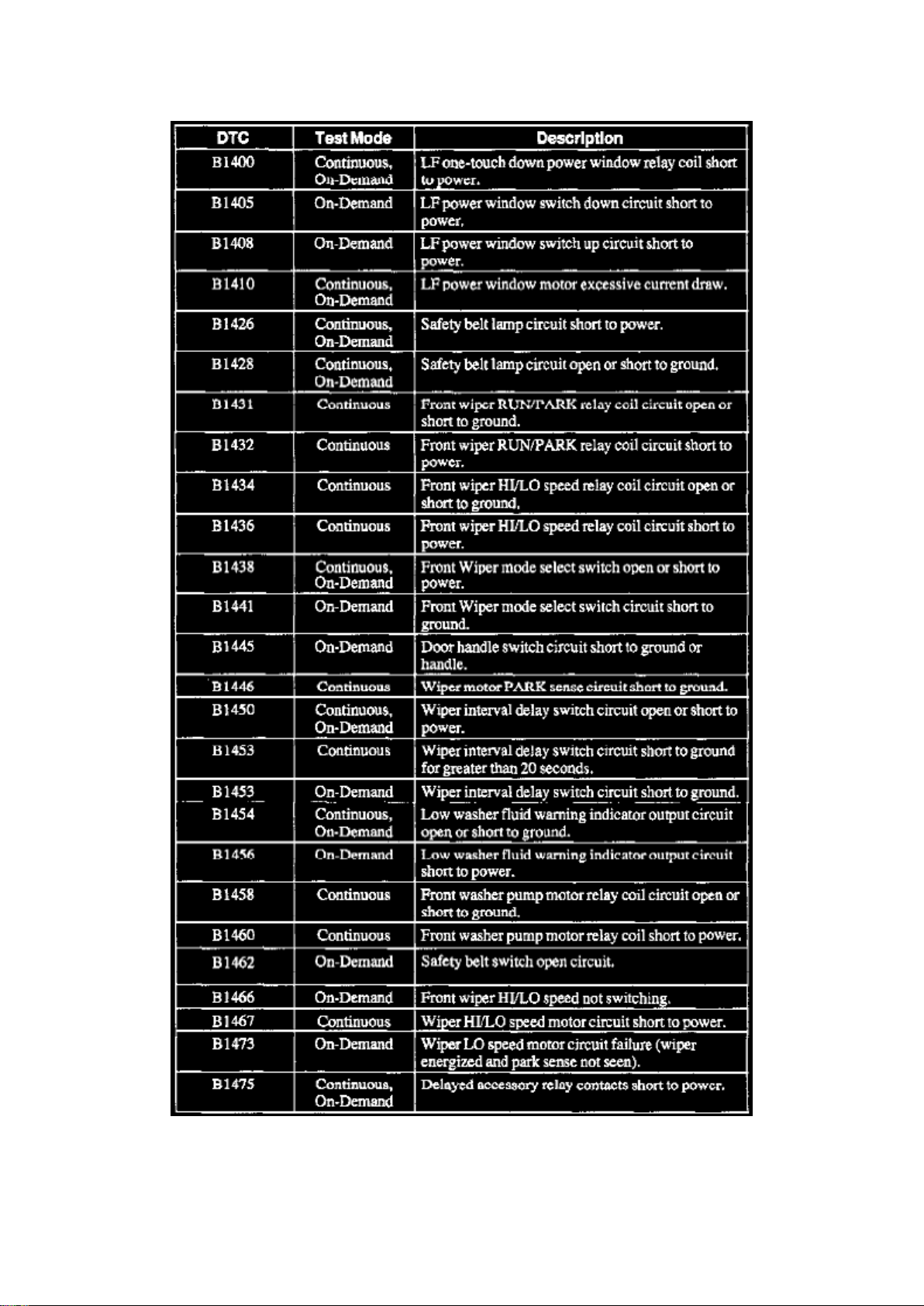
Part 3 Of 5
Page 83

Ford Expedition 2wd Workshop Manual (V8-281 4.6L VIN W EFI (1997))
Ford Workshop Manuals > Relays and Modules > Relays and Modules - Accessories and Optional Equipment >
Multifunction Electronic Control Module <--> [General Module] > Component Information > Testing and Inspection > Flow of
Diagnosis > Page 60
Page 84
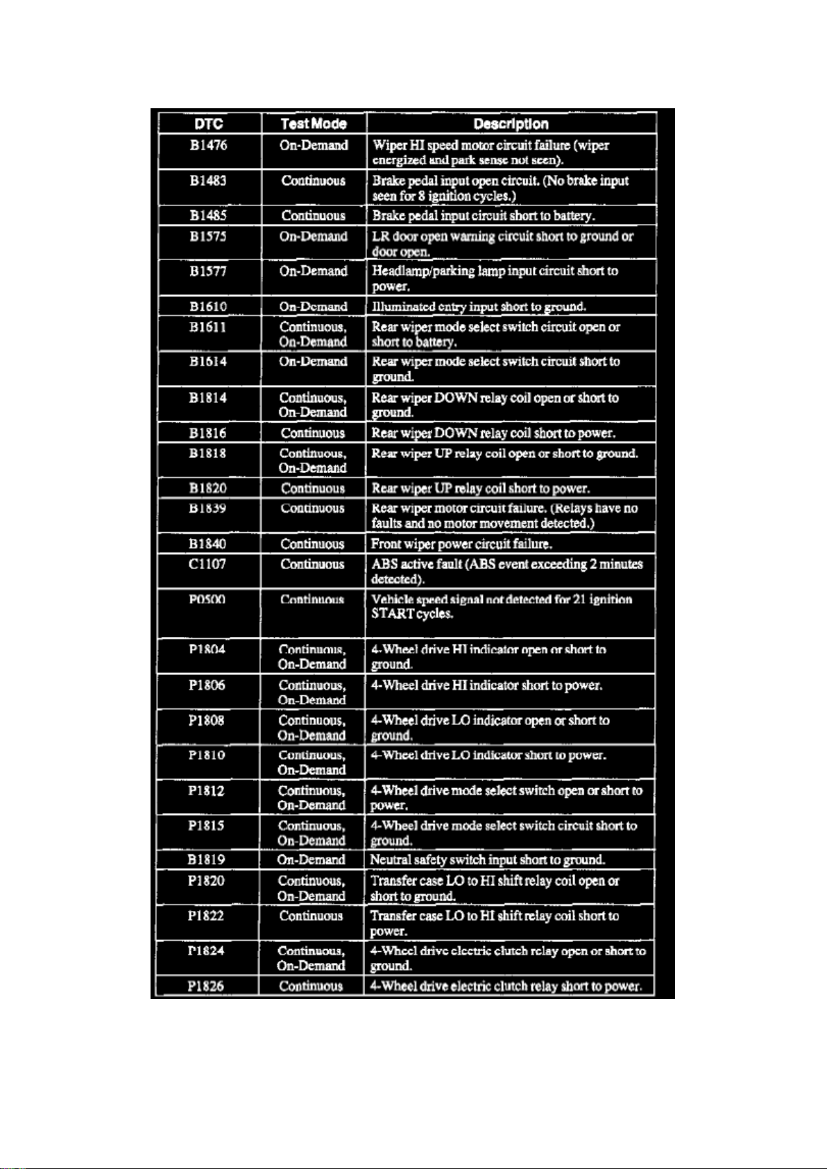
Part 4 Of 5
Page 85

Ford Expedition 2wd Workshop Manual (V8-281 4.6L VIN W EFI (1997))
Ford Workshop Manuals > Relays and Modules > Relays and Modules - Accessories and Optional Equipment >
Multifunction Electronic Control Module <--> [General Module] > Component Information > Testing and Inspection > Flow of
Diagnosis > Page 61
Page 86
Part 5 Of 5
Page 87
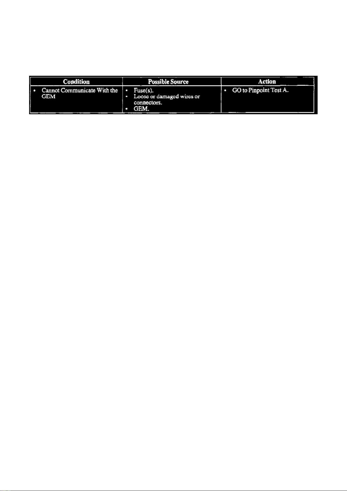
Ford Expedition 2wd Workshop Manual (V8-281 4.6L VIN W EFI (1997))
Ford Workshop Manuals > Relays and Modules > Relays and Modules - Accessories and Optional Equipment >
Multifunction Electronic Control Module <--> [General Module] > Component Information > Testing and Inspection > Flow of
Diagnosis > Page 62
Page 88
Ford Expedition 2wd Workshop Manual (V8-281 4.6L VIN W EFI (1997))
Ford Workshop Manuals > Relays and Modules > Relays and Modules - Accessories and Optional Equipment >
Multifunction Electronic Control Module <--> [General Module] > Component Information > Testing and Inspection > Flow of
Diagnosis > Page 63
Multifunction Electronic Control Module: Pinpoint Tests
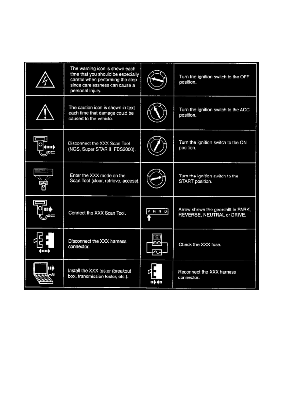
Pinpoint Test Icons
Pinpoint Test Step Icons Chart
In diagnosis and testing, you will see that a number of icons are used in the pinpoint test steps. The
icons will assist in diagnosing the vehicle concern in a timely manner. The icons that are used are
shown in the Pinpoint Test Step Icons chart.
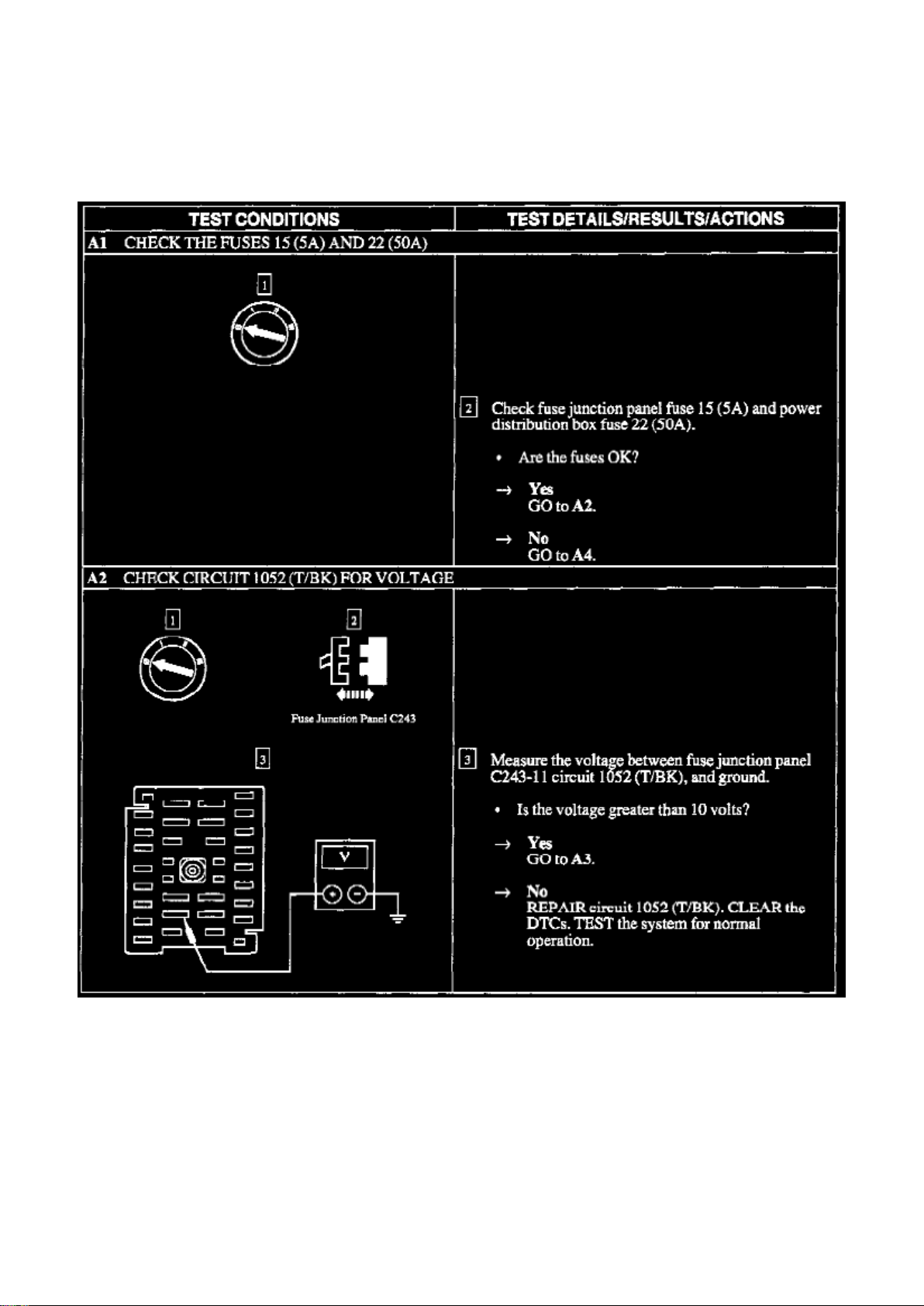
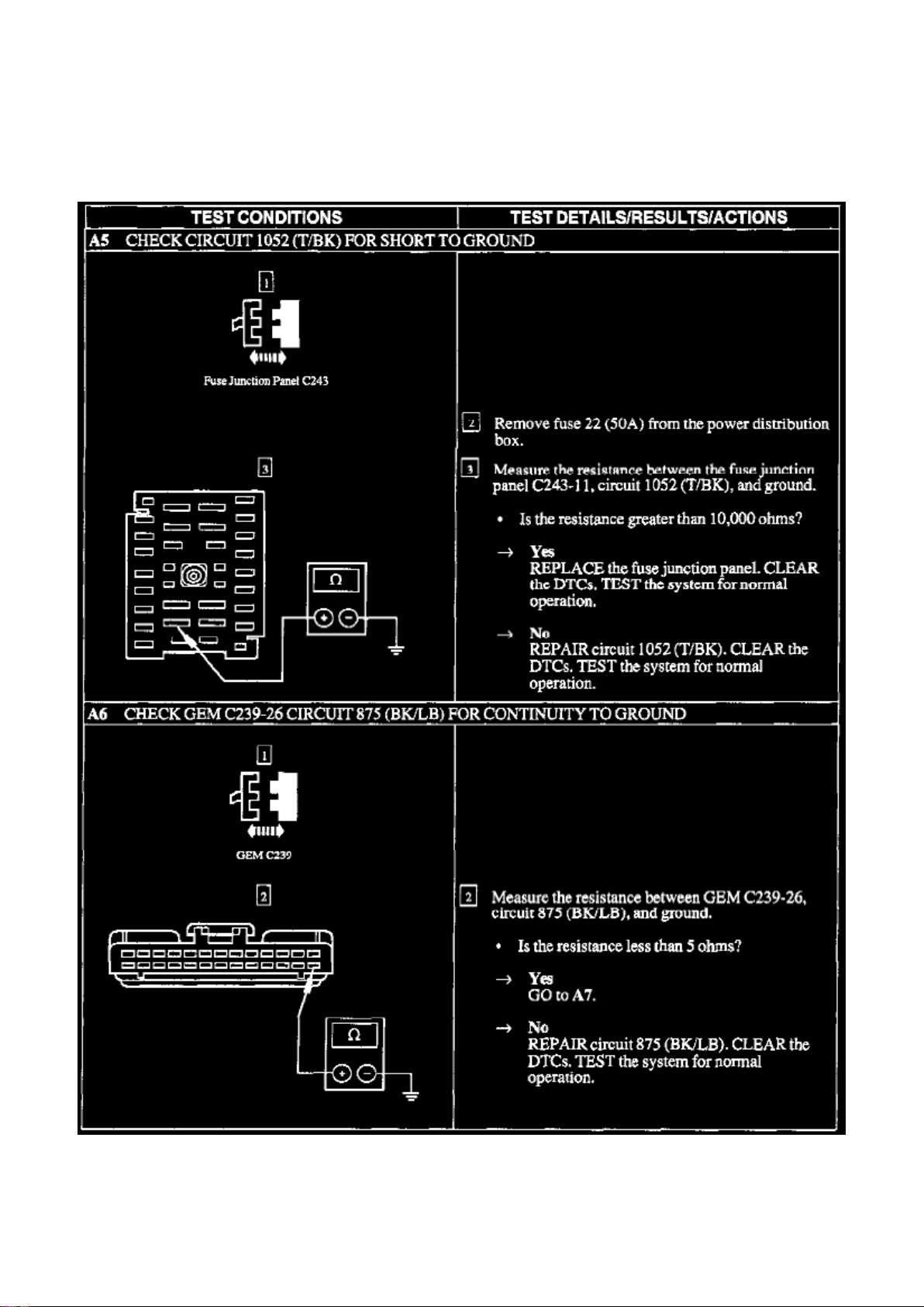
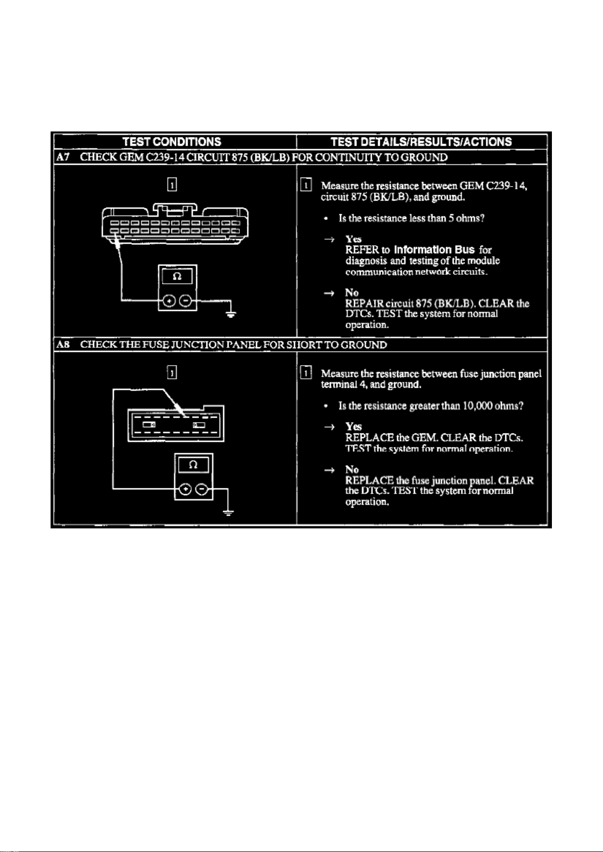
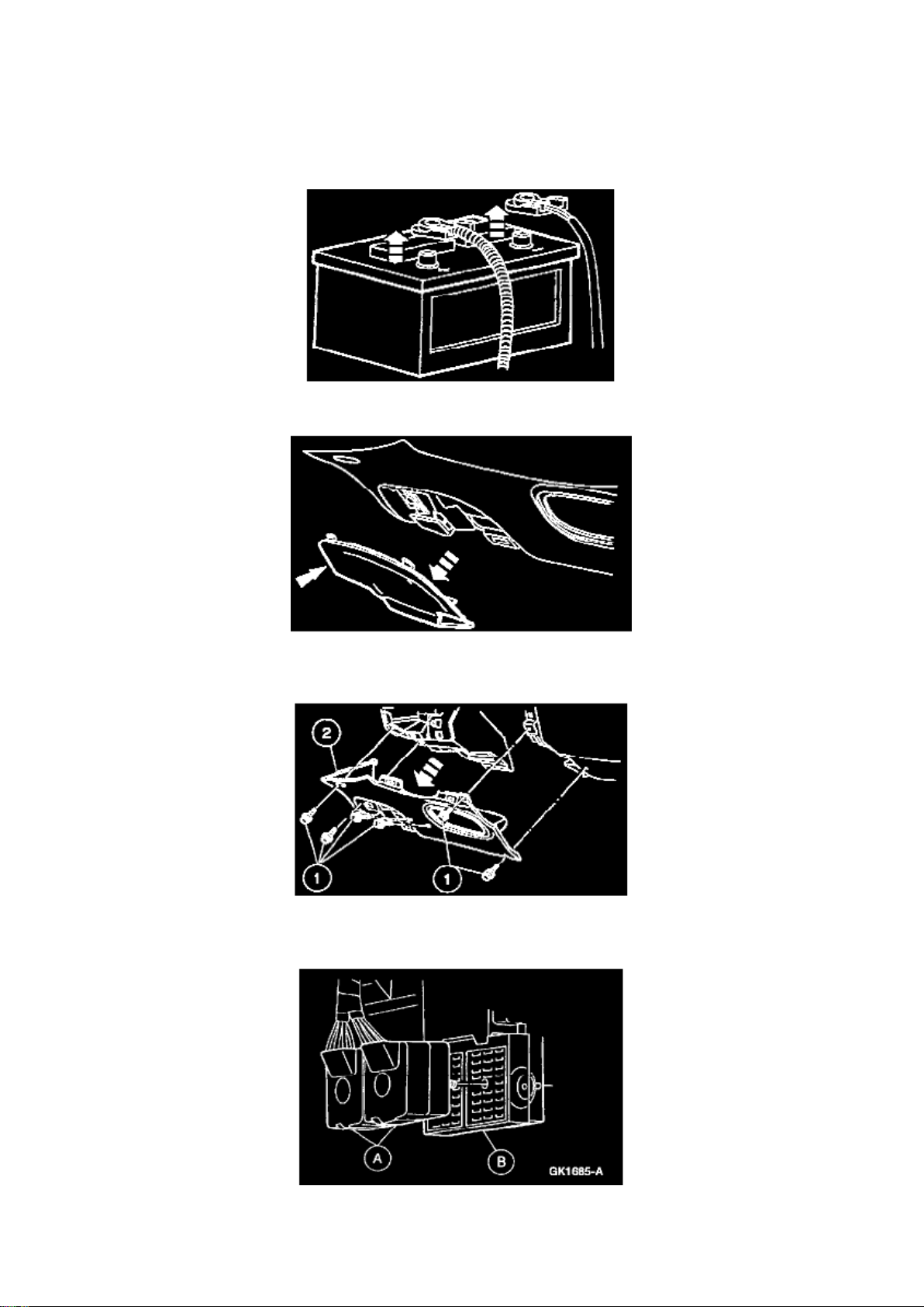
A: Cannot Communicate With the GEM
Page 89
Ford Expedition 2wd Workshop Manual (V8-281 4.6L VIN W EFI (1997))
Ford Workshop Manuals > Relays and Modules > Relays and Modules - Accessories and Optional Equipment >
Multifunction Electronic Control Module <--> [General Module] > Component Information > Testing and Inspection > Flow of
Diagnosis > Page 64
A1-A2
Page 90
Ford Expedition 2wd Workshop Manual (V8-281 4.6L VIN W EFI (1997))
Ford Workshop Manuals > Relays and Modules > Relays and Modules - Accessories and Optional Equipment >
Multifunction Electronic Control Module <--> [General Module] > Component Information > Testing and Inspection > Flow of
Diagnosis > Page 65
A3-A4
Page 91
Ford Expedition 2wd Workshop Manual (V8-281 4.6L VIN W EFI (1997))
Ford Workshop Manuals > Relays and Modules > Relays and Modules - Accessories and Optional Equipment >
Multifunction Electronic Control Module <--> [General Module] > Component Information > Testing and Inspection > Flow of
Diagnosis > Page 66
A5-A6
Page 92
Ford Expedition 2wd Workshop Manual (V8-281 4.6L VIN W EFI (1997))
Ford Workshop Manuals > Relays and Modules > Relays and Modules - Accessories and Optional Equipment >
Multifunction Electronic Control Module <--> [General Module] > Component Information > Testing and Inspection > Flow of
Diagnosis > Page 67
A7-A8
Page 93
Ford Expedition 2wd Workshop Manual (V8-281 4.6L VIN W EFI (1997))
Ford Workshop Manuals > Relays and Modules > Relays and Modules - Accessories and Optional Equipment >
Multifunction Electronic Control Module <--> [General Module] > Component Information > Testing and Inspection > Page 68
Page 94

Multifunction Electronic Control Module: Service and Repair
REMOVAL
1. Disconnect the positive or both battery cables.
2. Remove the cover from the instrument panel fuse junction panel. 3. Remove the lower
instrument panel steering column cover.
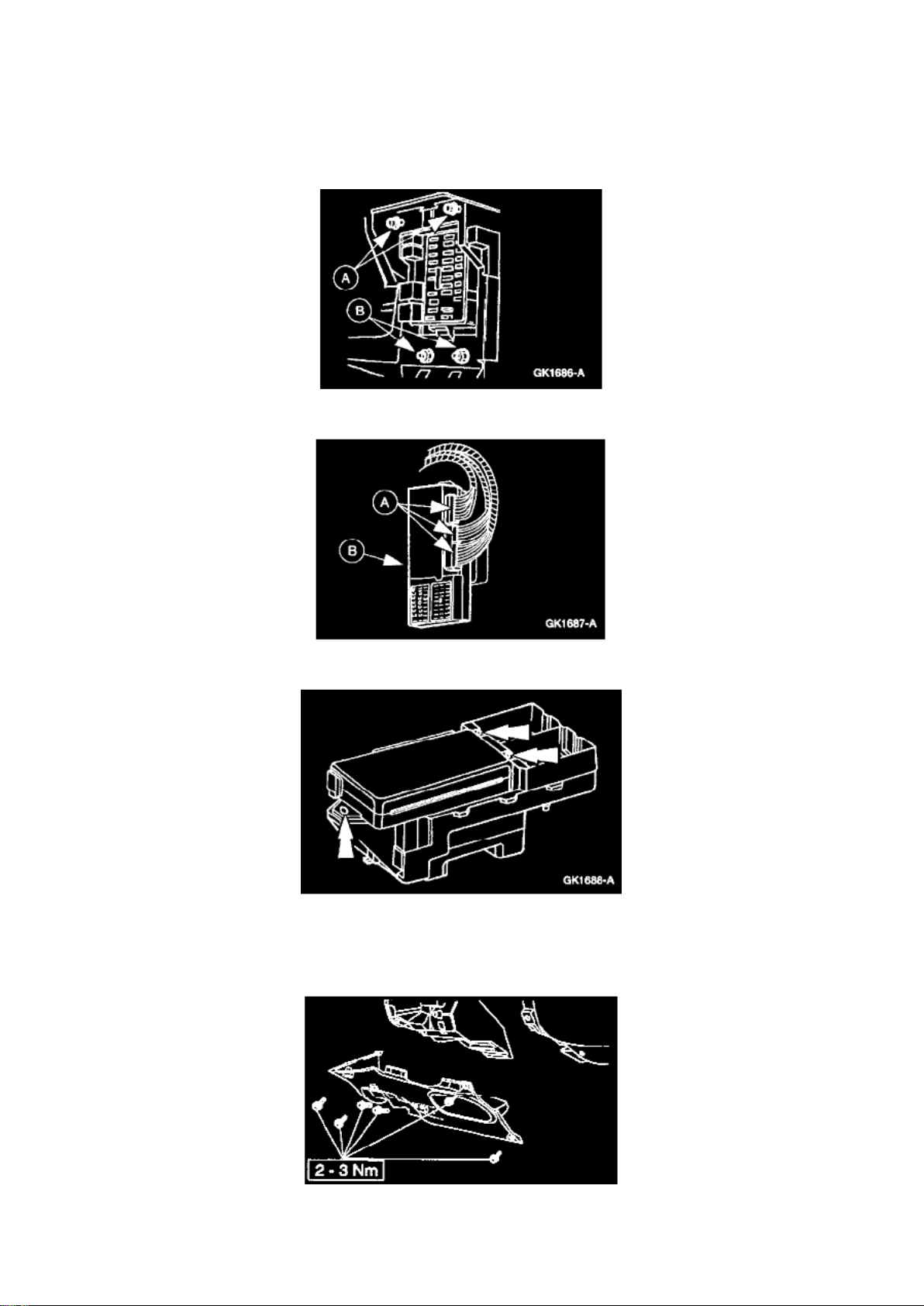
1. Remove the six lower instrument panel steering column cover bolts. 2. Remove the lower
instrument panel steering column cover.
4. Remove the two (A) bulkhead electrical connectors from the (B) instrument panel fuse junction
panel.
Page 95
Ford Expedition 2wd Workshop Manual (V8-281 4.6L VIN W EFI (1997))
Ford Workshop Manuals > Relays and Modules > Relays and Modules - Accessories and Optional Equipment >
Multifunction Electronic Control Module <--> [General Module] > Component Information > Testing and Inspection > Page 69
Page 96

5. Remove the two (A) instrument panel fuse junction panel bolts and remove the two (B) interior
fuse junction panel nuts.
6. Disconnect the three (A) GEM electrical connectors from the (B) GEM.
7. Remove the three GEM screws and the GEM.
INSTALLATION
1. To install, reverse the removal procedure. Check for proper operation.
2. Install the lower instrument panel steering column cover.
^ Position the lower instrument panel steering column cover.
^ Install the six screws.
NOTE: When the battery is disconnected and reconnected, some abnormal drive symptoms may
occur while the vehicle relearns its adaptive strategy. The vehicle may need to be driven 16 km (10
mi) or more to relearn the strategy.
Page 97
Ford Expedition 2wd Workshop Manual (V8-281 4.6L VIN W EFI (1997))
Ford Workshop Manuals > Relays and Modules > Relays and Modules - Accessories and Optional Equipment >
Multifunction Electronic Control Module <--> [General Module] > Component Information > Testing and Inspection > Page 70
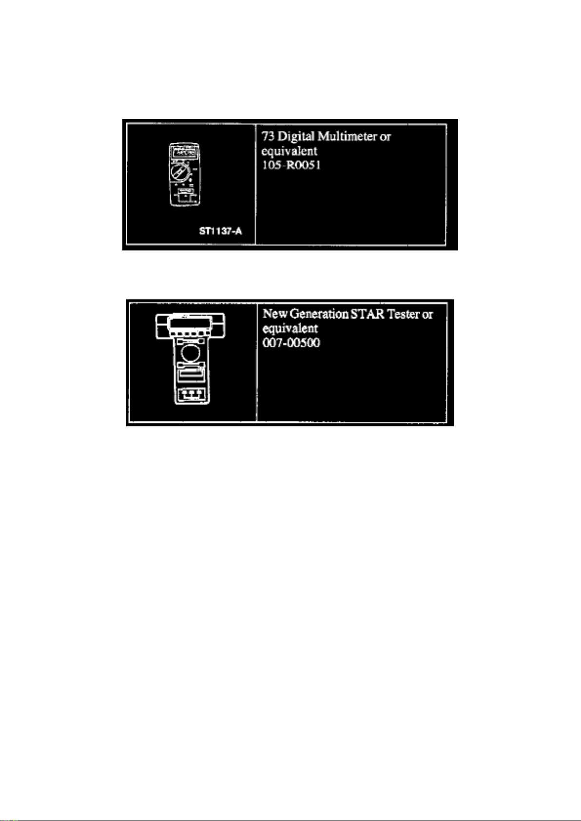
Multifunction Electronic Control Module: Tools and Equipment
Special Service Tool(s)
Page 98

Ford Expedition 2wd Workshop Manual (V8-281 4.6L VIN W EFI (1997))
Ford Workshop Manuals > Relays and Modules > Relays and Modules - Accessories and Optional Equipment > Keyless
Entry Module > Component Information > Specifications
Page 99

Keyless Entry Module: Specifications
RAP Module Nuts ................................................................................................................................
...................................................... 7 Nm (62.4 in lb)
Page 100
Ford Expedition 2wd Workshop Manual (V8-281 4.6L VIN W EFI (1997))
Ford Workshop Manuals > Relays and Modules > Relays and Modules - Accessories and Optional Equipment > Keyless
Entry Module > Component Information > Specifications > Page 74
 Loading...