

Page 1

SECTION 206-09: Vehicle Dynamic Systems 2008 E-Series Workshop Manual
Page
1
of 62008 E
-
Series Workshop Manual
1/18/2010
http://www.fordtechservice.dealerconnection.com/pubs/content/~WS8M/~MUS~LEN/19/
...
DIAGNOSIS AND TESTING
Procedure revision date: 08/12/2008
Anti-Lock Control — Traction Control and Stability Assist
Printable View (432 KB)
Special Tool(s)
Principles of Operation
ABS with Traction Control, Electronic Stability Control (ESC) and Roll Stability Control (RSC)
The ABS module with traction control and roll stability control (RSC) manages anti-lock braking to maintain vehicle control during deceleration and performs additional functions specific to
traction control and RSC.
ABS Operation
When the ignition switch is in the RUN position, the ABS module does a preliminary electrical check and, at approximately 20 km/h (12 mph), the hydraulic pump motor is turned on for
approximately 1/2 second. During this time a buzzing or humming noise may be heard and a vibration maybe felt in the brake pedal. This is a normal condition. Any malfunction of the ABS
disables the stability assist and the ABS warning indicator illuminates. However, the power-assist braking system functions normally.
The ABS module monitors and compares the rotational speed of each wheel. Wheel speeds are measured by the wheel speed sensor, which electrically senses each tooth of the sensor
ring as it passes through the magnetic field of the sensor. When the ABS module detects an impending wheel lock, the ABS module commands the hydraulic pump motor on and
commands the hydraulic control unit (HCU) to open and close the appropriate solenoid valves to modulate the brake pressure to the individual brake caliper(s). Once the affected wheel(s)
return to the desired speed, the ABS module commands the HCU to return the solenoid valves to their normal position and normal base brake operation is restored.
The ABS module must be configured when a new ABS module is installed.
Traction Control
When the drive wheels lose traction and begin to spin, with vehicle speed under 100 km/h (62 mph), the ABS module commands the hydraulic pump motor on and commands the HCU to
open and close the appropriate solenoid valves to modulate the brake pressure to the brake caliper(s) while simultaneously sending a request to the PCM over the high-speed controller
area network (HS-CAN) bus to reduce engine torque to maintain vehicle traction. The PCM accomplishes this by minor incremental timing changes and fewer fuel injector pulses until the
ABS module ends the request. The request ends when the driven wheel speed returns to the desired speed. After the vehicle speed exceeds 100 km/h (62 mph), the traction control is
accomplished only through the PCM torque control. The traction control system can be deactivated by pressing the stability/traction control switch in the instrument panel.
When the traction control system activates, any of the following can occur:
A small deceleration or a reduction in the acceleration of the vehicle
The traction control indicator in the instrument cluster flashes
If the driver's foot is on the brake pedal, a vibration will be felt in the pedal much like ABS
Electronic Stability Control (ESC)
The electronic stability control (ESC) system constantly monitors the vehicle motion relative to the intended course. This is done by using sensors to compare the steering input and the yaw
rate sensor with that of the actual vehicle motion. The ESC system monitors information from the throttle position (TP) sensor, the steering wheel rotation sensor (steering wheel angle and
rate of change) and a yaw rate sensor (integral to the stability control sensor cluster) that measures changes in vehicle direction. If the ESC system determines from all these inputs that the
vehicle is unable to travel in the intended direction, the system adjusts the brake torque at specific wheels in response to direct measurement of the vehicle motion and reduces engine
torque to allow the vehicle to follow the intended course. The ESC system can be deactivated by pressing the stability/traction control switch in the instrument panel.
When the ESC system activates, any of the following can occur:
A rumble or grinding sound much like ABS or traction control
A small deceleration or a reduction in the acceleration of the vehicle
The roll stability control (RSC) indicator flashes
If the driver's foot is on the brake pedal, a vibration will be felt in the pedal much like ABS
Roll Stability Control (RSC)
The roll stability control (RSC) system constantly monitors the vehicle motion relative to the intended course. This is done by using sensors to compare the steering input and brake
application with that of the actual vehicle motion. The system does not activate when the vehicle is traveling in reverse; however, the standard ABS and traction control continue to function
73III Automotive Meter
105-R0057 or equivalent
Flex Probe Kit
105-R025B or equivalent
Rotunda Active Wheel Speed Sensor Tester
105-R0110
Vehicle Communication Module (VCM) and Integrated Diagnostic System
(IDS) software with appropriate hardware, or equivalent scan tool
Page 2

as usual. The RSC system monitors information from the wheel speed sensors, the throttle position sensor, the steering wheel rotation sensor (steering wheel angle and rate of change) and
Page
2
of 62008 E
-
Series Workshop Manual
1/18/2010
http://www.fordtechservice.dealerconnection.com/pubs/content/~WS8M/~MUS~LEN/19/
...
a roll-rate sensor (integral to the stability control sensor cluster) that measures changes in vehicle motion. If the RSC system determines from all these inputs that conditions exist for a
potential roll-over event, the system adjusts the brake torque at specific wheels in response to direct measurement of the vehicle roll motion and reduces engine torque to make the vehicle
more stable. By adjusting brake torque, the system can reduce the cornering forces and, therefore, the total roll moment acting on the vehicle. The RSC system can be deactivated by
pressing the stability/traction control switch in the instrument panel.
When the RSC system activates, any of the following can occur:
A rumble or grinding sound much like ABS or traction control
A small deceleration or a reduction in the acceleration of the vehicle
The RSC indicator flashes
If the driver's foot is on the brake pedal, a vibration will be felt in the pedal much like ABS
Some drivers may notice a slight movement of the brake pedal when the system checks itself. The brake pedal moves when an active test of the brake booster is run. During this test a
small amount of pressure is generated at the master cylinder, but no pressure is generated in the brake calipers.
Stability/Traction Control Switch
The stability/traction control switch is hard-wired to the instrument cluster module. The instrument cluster module communicates the stability/traction control switch status to the ABS module
via the HS-CAN bus.
The stability/traction control switch allows the driver to control use of the ESC/RSC and traction control system. This is independent of the ABS function, which cannot be switched OFF by
the driver. The ESC/RSC and traction control system status is indicated by a light in the stability/traction control switch. When the stability/traction control switch is set to OFF, the system is
disabled at and below 32 km/h (20 mph). The system will automatically restore to full functionality every time the vehicle speed exceeds 32 km/h (20 mph) or when the ignition switch is
cycled from OFF to RUN. However, the stability/traction control switch OFF indicator remains illuminated until the switch is pressed a second time. The ABS function continues to work as
designed unless the yellow ABS warning indicator is illuminated. Normal braking function always occurs, unless the red brake warning indicator is illuminated.
Electronic Brake Distribution (EBD)
The HCU is used as an electronic proportioning valve for electronic brake distribution (EBD). The HCU controls the brake fluid pressure to the rear brakes to prevent them from applying
before the front brakes. If ABS is disabled due to DTCs being present in the ABS module, EBD will also be disabled. Instrument cluster failure or a missing instrument cluster message on
the HS-CAN bus will also disable EBD.
Stability Control Sensor Cluster
The sensor cluster (also called inertial module) consists of the yaw rate sensor, roll rate sensor, lateral accelerometer and longitudinal accelerometer. The lateral accelerometer measures
the acceleration which corresponds to the force involved when the vehicle slides sideways. This acceleration has 2 forms. The first is the centrifugal acceleration which is generated when
the vehicle travels around in a circle. The second is the acceleration due to gravity. On level ground there is no contribution from this acceleration. However, if the vehicle is parked
sideways on a bank or incline, the sensor measures some lateral acceleration due to gravity even though the vehicle is not moving.
The longitudinal accelerometer measures the acceleration corresponding to the force involved when the vehicle moves forward and rearward in the horizontal plane, along the centerline of
the vehicle's front and rear wheels.
The yaw rate sensor measures the relative vehicle motion about the vertical axis through its center of gravity.
The roll rate sensor measures the rate of rotation along the front to rear horizontal axis.
Steering Wheel Rotation Sensor
The steering wheel rotation sensor measures the rate of rotation of the steering wheel by monitoring the steering wheel rotation ring as it passes through the sensor gap. The steering wheel
rotation sensor uses 2 signal lines to transmit information to the ABS module about whether the steering wheel is being turned left or right and how far it is being turned. The steering wheel
rotation sensor does not indicate the absolute position of the steering wheel relative to straight-ahead. The stability assist system learns this position by comparing the steering wheel
position with other signals and storing the position it has learned. The stability assist system confirms this position and modifies it as necessary during every new driving cycle.
ABS Module Calibration
If installing a new ABS module, HCU, steering wheel rotation sensor or stability control sensor cluster, the calibration procedure must be carried out. The calibration procedure is required
for the ABS module to learn the "zero-position" of the various ESC/RSC sensors and components.
To calibrate the ABS module, connect the scan tool and carry out the Interactive Vehicle Dynamics (IVD) Initialization sequence.
If a DTC is logged for any component of the ESC/RSC system, the DTC must be cleared or repaired before carrying out the initialization sequence. The need to calibrate the ABS module is
also indicated by the RSC indicator on the instrument cluster module flashing once every 2 seconds. The indicator flashes after clearing the DTCs that are associated with the RSC system.
If a DTC is retrieved after calibration, refer to the ABS Module DTC Chart in this section.
When carrying out the initialization sequence for the ABS module, the vehicle must be on a level surface, must not be moving and the ignition switch must be in the RUN position.
When carrying out the initialization sequence for the ABS module after installing a new steering wheel rotation sensor, the ignition switch must be in the RUN position with the engine
running and the steering wheel must be rotated back and forth from lock position to lock position.
Inspection and Verification
Identifying the Brake System
Two ABS systems are available for this vehicle: standard ABS and ABS enhanced with traction control and stability assist. ABS with traction control and stability assist may also be called
electronic stability control (ESC), roll stability control (RSC), AdvanceTrac®, or interactive vehicle dynamics (IVD) by the scan tool and other service publications.
Vehicles that are equipped with traction control and stability assist can be identified by the presence of individual left and right rear wheel speed sensors.
Vehicles with standard ABS can be identified by the absence of rear wheel speed sensors.
If the vehicle is equipped with standard ABS, refer to Anti-Lock Control in this section to continue diagnosis of this system.
1. Verify the customer concern.
Page 3
2. Verify the stop lamps operate correctly by pressing and releasing the brake pedal with the ignition switch in the OFF position. If the stoplamps do not operate correctly, refer to
Steering wheel rotation sensor ring
Central junction box (CJB) fuse(s):
Page
3
of 62008 E
-
Series Workshop Manual
1/18/2010
http://www.fordtechservice.dealerconnection.com/pubs/content/~WS8M/~MUS~LEN/19/
...
Section 417-01. If the stoplamps operate correctly, proceed to the next step.
3. Verify the base brake system operates correctly. If any concerns are present, address them before continuing with any ABS concerns. Refer to Section 206-00. If the base brake
system operates correctly, proceed to the next step.
4. Visually inspect for obvious signs of mechanical or electrical damage.
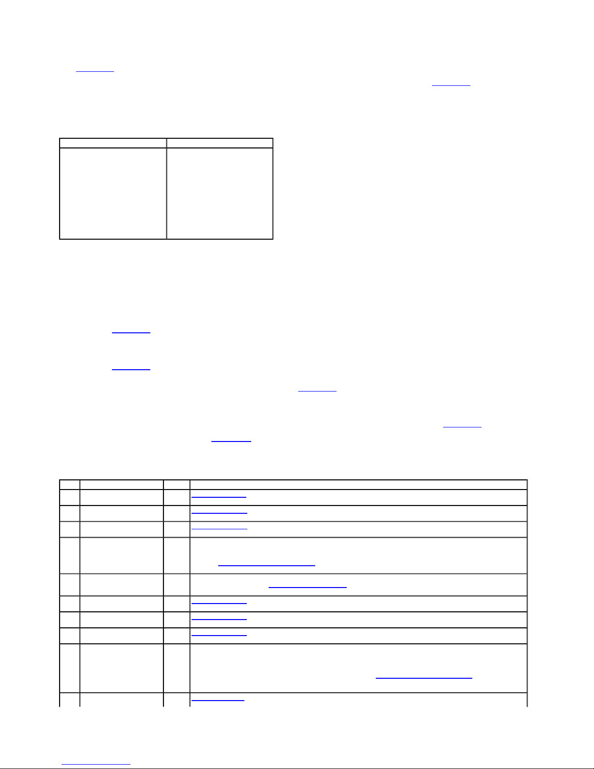
Visual Inspection Chart
Mechanical Electrical
Base brake system
Hydraulic control unit (HCU)
Tire pressure
Tire size or mismatched tires
Wheel speed sensor ring
5. If an obvious cause for an observed or reported concern is found, correct the cause (if possible) before proceeding to the next step.
6. NOTE: Make sure to use the latest scan tool software release.
If the cause is not visually evident, connect the scan tool to the data link connector (DLC).
7. NOTE: The vehicle communication module (VCM) LED prove out confirms power and ground from the DLC are provided to the VCM.
If the scan tool does not communicate with the VCM:
check the VCM connection to the vehicle.
check the scan tool connection to the VCM.
refer to Section 418-00, No Power To The Scan Tool, to diagnose no communication with the scan tool.
8. If the scan tool does not communicate with the vehicle:
verify the ignition key is in the ON position.
verify the scan tool operation with a known good vehicle.
refer to Section 418-00 to diagnose no response from the PCM.
9. Carry out the network test.
If the scan tool responds with no communication for one or more modules, refer to Section 418-00.
If the network test passes, retrieve and record continuous memory DTCs.
10. Clear the continuous DTCs and carry out the self-test diagnostics for the ABS module and the instrument cluster.
11. If the DTCs retrieved are related to the concern, go to the ABS Module DTC Chart or the Instrument Cluster DTC Chart. For all other DTCs, refer to Section 419-10.
12. If no DTCs related to the concern are retrieved, GO to Symptom Chart.
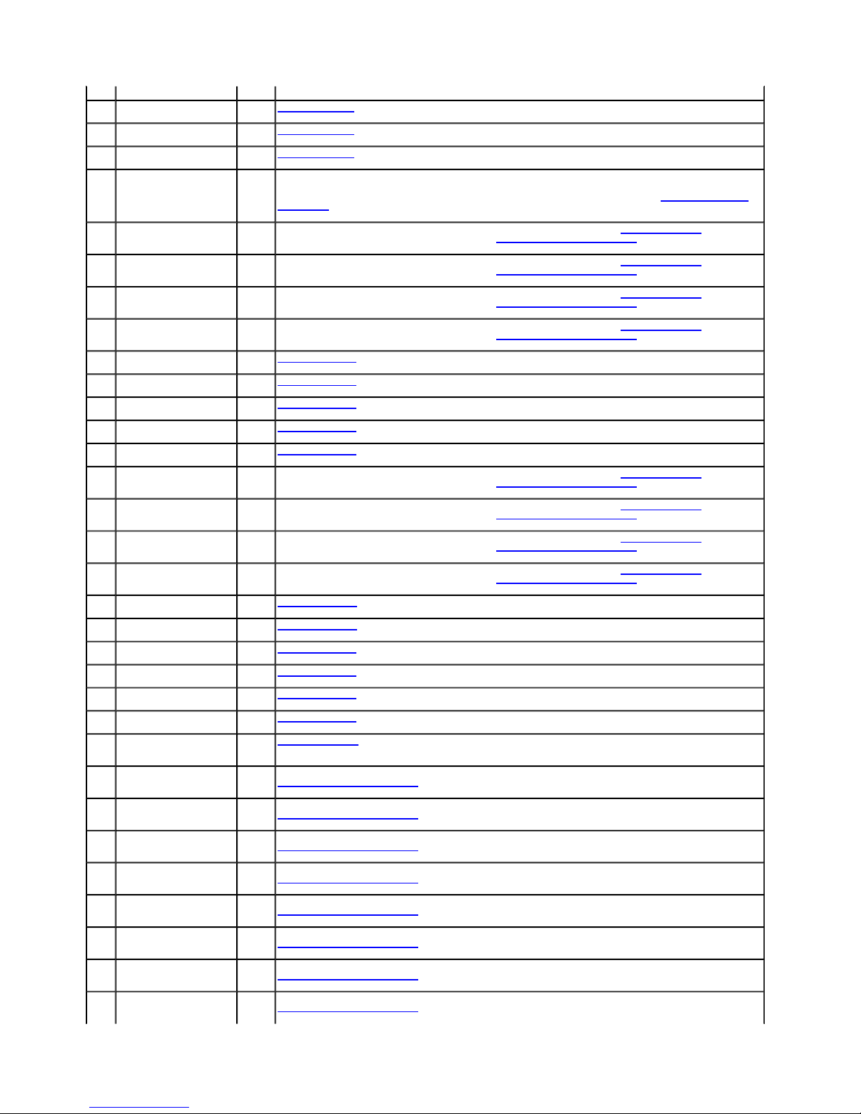
ABS Module DTC Chart
DTC Description Source Action
B1104 Steering Angle Sensor Signal
Error
B1317 Battery Voltage High ABS
B1318 Battery Voltage Low ABS
B1342 ECU is Faulted ABS
B211B Satellite ECU (Stability Control
Sensor Cluster) is Faulted
B2900 VIN Mismatch ABS
C1095 ABS Hydraulic Pump Motor
Circuit Failure
C1096 ABS Hydraulic Pump Motor
Circuit Open
C1115 ABS Power Relay Output Short
Circuit to Battery
C1145 RF Wheel Speed Sensor Input ABS GO to Pinpoint Test I.
ABS module
Battery junction box (BJB) fuse(s):
11 (40A)
16 (40A)
Brake pedal position (BPP) switch
2 (10A)
22 (15A)
Stability control sensor cluster
Stability/traction control switch
Steering wheel rotation sensor
Traction control switch
Wheel speed sensor
Wiring, terminals or connectors
ABS
GO to Pinpoint Test K.
Module
GO to Pinpoint Test G.
Module
GO to Pinpoint Test G.
Module
NOTE: If other DTCs are present, REPAIR them before installing a new component.
Module
CLEAR the DTCs. CARRY OUT the self-test and RETRIEVE the DTCs. If DTC is retrieved again, INSTALL a new ABS module.
REFER to Anti-Lock Brake System (ABS) Module in this section. Using the scan tool, CARRY OUT the IVD Initialization sequence.
CLEAR the DTCs. CARRY OUT the self-test with the brake pedal not applied.
ABS
CHECK the stability control sensor cluster electrical connector and wiring for water intrusion. REPAIR as necessary. If OK, INSTALL a
Module
new sensor cluster. REFER to Stability Control Sensor Cluster in this section. CLEAR the DTCs. CARRY OUT the self-test with the
brake pedal not applied.
GO to Pinpoint Test R.
Module
ABS
GO to Pinpoint Test H.
Module
ABS
GO to Pinpoint Test H.
Module
ABS
NOTE: If other DTCs are present, REPAIR them before installing a new component.
Module
CLEAR all DTCs. TEST DRIVE the vehicle above 32 km/h (20 mph) and CARRY OUT at least one ABS stop. RETRIEVE the DTCs.
If DTC C1115 is retrieved again, INSTALL a new ABS module. REFER to Anti-Lock Brake System (ABS) Module in this section. Using
the scan tool, CARRY OUT the IVD Initialization sequence. CLEAR the DTCs. CARRY OUT the self-test with the brake pedal not
applied.
Page 4
Circuit Failure Module
ABS Outlet Valve Coil LF Circuit
ABS Outlet Valve Coil LF Circuit
Page
4
of 62008 E
-
Series Workshop Manual
1/18/2010
http://www.fordtechservice.dealerconnection.com/pubs/content/~WS8M/~MUS~LEN/19/
...
C1155 LF Wheel Speed Sensor Input
Circuit Failure
C1165 RR Wheel Speed Sensor Input
Circuit Failure
C1175 LR Wheel Speed Sensor Input
Circuit Failure
C1185 ABS Power Relay Output
Circuit Failure
C1194
Failure
C1198 ABS Inlet Valve Coil LF Circuit
Failure
C1210 ABS Outlet Valve Coil RF
Circuit Failure
C1214 ABS Inlet Valve Coil RF Circuit
Failure
C1222 Wheel Speed Mismatch ABS
C1233 LF Wheel Speed Input Signal
Missing
C1234 RF Wheel Speed Input Signal
Missing
C1235 RR Wheel Speed Input Signal
Missing
C1236 LR Wheel Speed Input Signal
Missing
C1242 ABS Outlet Valve Coil LR
Circuit Failure
C1246 ABS Outlet Valve Coil RR
Circuit Failure
C1250 ABS Inlet Valve Coil LR Circuit
Failure
C1254 ABS Inlet Valve Coil RR Circuit
Failure
C1277 Steering Wheel Angle 1 and 2
Circuit Failure
C1278 Steering Wheel Angle 1 and 2
Signal Faulted
C1279 Yaw Rate Sensor Circuit Failure ABS
C1280 Yaw Rate Sensor Signal Fault ABS
C1281 Lateral Accelerometer Circuit
Failure
C1282 Lateral Accelerometer Signal
Fault
C1288 Pressure Transducer
Main/Primary Input Circuit
Failure
C1329 ABS Outlet Valve Coil RF
Circuit Excessive Temperature
C1330 ABS Outlet Valve Coil LR
Circuit Excessive Temperature
C1331 ABS Outlet Valve Coil RR
Circuit Excessive Temperature
C1332
Excessive Temperature
C1333 ABS Inlet Valve Coil LR Circuit
Excessive Temperature
C1334 ABS Inlet Valve Coil LF Circuit
Excessive Temperature
C1335 ABS Inlet Valve Coil RF Circuit
Excessive Temperature
C1336 ABS Inlet Valve Coil RR Circuit
Excessive Temperature
ABS
Module
ABS
Module
ABS
Module
ABS
Module
ABS
Module
ABS
Module
ABS
Module
ABS
Module
Module
ABS
Module
ABS
Module
ABS
Module
ABS
Module
ABS
Module
ABS
Module
ABS
Module
ABS
Module
ABS
Module
ABS
Module
Module
Module
ABS
Module
ABS
Module
ABS
Module
ABS
Module
ABS
Module
ABS
Module
ABS
Module
ABS
Module
ABS
Module
ABS
Module
ABS
Module
GO to Pinpoint Test I.
GO to Pinpoint Test I.
GO to Pinpoint Test I.
NOTE: REPAIR all other DTCs prior to diagnosing this one.
CLEAR all DTCs. RETRIEVE DTCs. If the DTC is retrieve again, INSTALL a new ABS module. REFER to Anti-Lock Brake System
(ABS) Module in this section. Using the scan tool, CARRY OUT the IVD Initialization sequence. CLEAR the DTCs. CARRY OUT the
self-test with the brake pedal not applied.
CLEAR all DTCs. DRIVE the vehicle. RETRIEVE the DTCs. If multiple coil DTCs are retrieved, GO to Pinpoint Test G. If only DTC
C1194 is retrieved, INSTALL a new ABS module. REFER to Anti-Lock Brake System (ABS) Module in this section. Using the scan
tool, CARRY OUT the IVD Initialization sequence. CLEAR the DTCs. CARRY OUT the self-test with the brake pedal not applied.
CLEAR all DTCs. DRIVE the vehicle. RETRIEVE the DTCs. If multiple coil DTCs are retrieved, GO to Pinpoint Test G. If only DTC
C1198 is retrieved, INSTALL a new ABS module. REFER to Anti-Lock Brake System (ABS) Module in this section. Using the scan
tool, CARRY OUT the IVD Initialization sequence. CLEAR the DTCs. CARRY OUT the self-test with the brake pedal not applied.
CLEAR all DTCs. DRIVE the vehicle. RETRIEVE the DTCs. If multiple coil DTCs are retrieved, GO to Pinpoint Test G. If only DTC
C1210 is retrieved, INSTALL a new ABS module. REFER to Anti-Lock Brake System (ABS) Module in this section. Using the scan
tool, CARRY OUT the IVD Initialization sequence. CLEAR the DTCs. CARRY OUT the self-test with the brake pedal not applied.
CLEAR all DTCs. DRIVE the vehicle. RETRIEVE the DTCs. If multiple coil DTCs are retrieved, GO to Pinpoint Test G. If only DTC
C1214 is retrieved, INSTALL a new ABS module. REFER to Anti-Lock Brake System (ABS) Module in this section. Using the scan
tool, CARRY OUT the IVD Initialization sequence. CLEAR the DTCs. CARRY OUT the self-test with the brake pedal not applied.
GO to Pinpoint Test J.
GO to Pinpoint Test J.
GO to Pinpoint Test J.
GO to Pinpoint Test J.
GO to Pinpoint Test J.
CLEAR all DTCs. DRIVE the vehicle. RETRIEVE the DTCs. If multiple coil DTCs are retrieved, GO to Pinpoint Test G. If only DTC
C1242 is retrieved, INSTALL a new ABS module. REFER to Anti-Lock Brake System (ABS) Module in this section. Using the scan
tool, CARRY OUT the IVD Initialization sequence. CLEAR the DTCs. CARRY OUT the self-test with the brake pedal not applied.
CLEAR all DTCs. DRIVE the vehicle. RETRIEVE the DTCs. If multiple coil DTCs are retrieved, GO to Pinpoint Test G. If only DTC
C1246 is retrieved, INSTALL a new ABS module. REFER to Anti-Lock Brake System (ABS) Module in this section. Using the scan
tool, CARRY OUT the IVD Initialization sequence. CLEAR the DTCs. CARRY OUT the self-test with the brake pedal not applied.
CLEAR all DTCs. DRIVE the vehicle. RETRIEVE the DTCs. If multiple coil DTCs are retrieved, GO to Pinpoint Test G. If only DTC
C1250 is retrieved, INSTALL a new ABS module. REFER to Anti-Lock Brake System (ABS) Module in this section. Using the scan
tool, CARRY OUT the IVD Initialization sequence. CLEAR the DTCs. CARRY OUT the self-test with the brake pedal not applied.
CLEAR all DTCs. DRIVE the vehicle. RETRIEVE the DTCs. If multiple coil DTCs are retrieved, GO to Pinpoint Test G. If only DTC
C1254 is retrieved, INSTALL a new ABS module. REFER to Anti-Lock Brake System (ABS) Module in this section. Using the scan
tool, CARRY OUT the IVD Initialization sequence. CLEAR the DTCs. CARRY OUT the self-test with the brake pedal not applied.
GO to Pinpoint Test K.
GO to Pinpoint Test K.
GO to Pinpoint Test L.
GO to Pinpoint Test L.
GO to Pinpoint Test L.
GO to Pinpoint Test L.
GO to Pinpoint Test M.
CLEAR all DTCs. DRIVE the vehicle. RETRIEVE the DTCs. If the DTC is retrieved again, INSTALL a new ABS module. REFER to
Anti-Lock Brake System (ABS) Module in this section. Using the scan tool, CARRY OUT the IVD Initialization sequence. CLEAR the
DTCs. CARRY OUT the self-test with the brake pedal not applied.
CLEAR all DTCs. DRIVE the vehicle. RETRIEVE the DTCs. If the DTC is retrieved again, INSTALL a new ABS module. REFER to
Anti-Lock Brake System (ABS) Module in this section. Using the scan tool, CARRY OUT the IVD Initialization sequence. CLEAR the
DTCs. CARRY OUT the self-test with the brake pedal not applied.
CLEAR all DTCs. DRIVE the vehicle. RETRIEVE the DTCs. If the DTC is retrieved again, INSTALL a new ABS module. REFER to
Anti-Lock Brake System (ABS) Module in this section. Using the scan tool, CARRY OUT the IVD Initialization sequence. CLEAR the
DTCs. CARRY OUT the self-test with the brake pedal not applied.
CLEAR all DTCs. DRIVE the vehicle. RETRIEVE the DTCs. If the DTC is retrieved again, INSTALL a new ABS module. REFER to
Anti-Lock Brake System (ABS) Module in this section. Using the scan tool, CARRY OUT the IVD Initialization sequence. CLEAR the
DTCs. CARRY OUT the self-test with the brake pedal not applied.
CLEAR all DTCs. DRIVE the vehicle. RETRIEVE the DTCs. If the DTC is retrieved again, INSTALL a new ABS module. REFER to
Anti-Lock Brake System (ABS) Module in this section. Using the scan tool, CARRY OUT the IVD Initialization sequence. CLEAR the
DTCs. CARRY OUT the self-test with the brake pedal not applied.
CLEAR all DTCs. DRIVE the vehicle. RETRIEVE the DTCs. If the DTC is retrieved again, INSTALL a new ABS module. REFER to
Anti-Lock Brake System (ABS) Module in this section. Using the scan tool, CARRY OUT the IVD Initialization sequence. CLEAR the
DTCs. CARRY OUT the self-test with the brake pedal not applied.
CLEAR all DTCs. DRIVE the vehicle. RETRIEVE the DTCs. If the DTC is retrieved again, INSTALL a new ABS module. REFER to
Anti-Lock Brake System (ABS) Module in this section. Using the scan tool, CARRY OUT the IVD Initialization sequence. CLEAR the
DTCs. CARRY OUT the self-test with the brake pedal not applied.
CLEAR all DTCs. DRIVE the vehicle. RETRIEVE the DTCs. If the DTC is retrieved again, INSTALL a new ABS module. REFER to
Anti-Lock Brake System (ABS) Module in this section. Using the scan tool, CARRY OUT the IVD Initialization sequence. CLEAR the
Page 5
C1404 Traction Control Valve Rear
Page
5
of 62008 E
-
Series Workshop Manual
1/18/2010
http://www.fordtechservice.dealerconnection.com/pubs/content/~WS8M/~MUS~LEN/19/
...
Circuit Failure
C1410 Traction Control Valve LF
Circuit Failure
C1446 Base Brake Failure/Brake
Switch Stuck or Inoperative
C1516 Roll Rate Sensor Signal Fault ABS
C1517 Roll Rate Sensor Circuit Fault ABS
C1527 Traction Control Rear Valve
Circuit Excessive Temperature
C1528 Traction Control LF Valve
Circuit Excessive Temperature
C1530 Dynamic Stability Control RF
Valve Circuit Excessive
Temperature
C1531 Dynamic Stability Control LF
Valve Circuit Excessive
Temperature
C1730 Reference Voltage Out of
Range (+5 V)
C1957 Dynamic Stability Control Valve
RF Circuit Failure
C1958 Dynamic Stability Control Valve
LF Circuit Failure
C1963 Stability Control Inhibit Warning ABS
C1991 Module Calibration Failure ABS
C2769 Longitudinal Acceleration
Sensor Electrical Failure
C2770 Longitudinal Acceleration
Sensor Plausibility Failure
U0028 Vehicle Communication Bus Off ABS
U0073 Control Module Communication
Bus Off
U0115 Lost Communication with
ECM/PCM - Secondary
U0155 Lost Communication with
Instrument Panel Cluster
U2050 No Application Present ABS
U2051 One or More Calibration Files
Missing/Corrupt
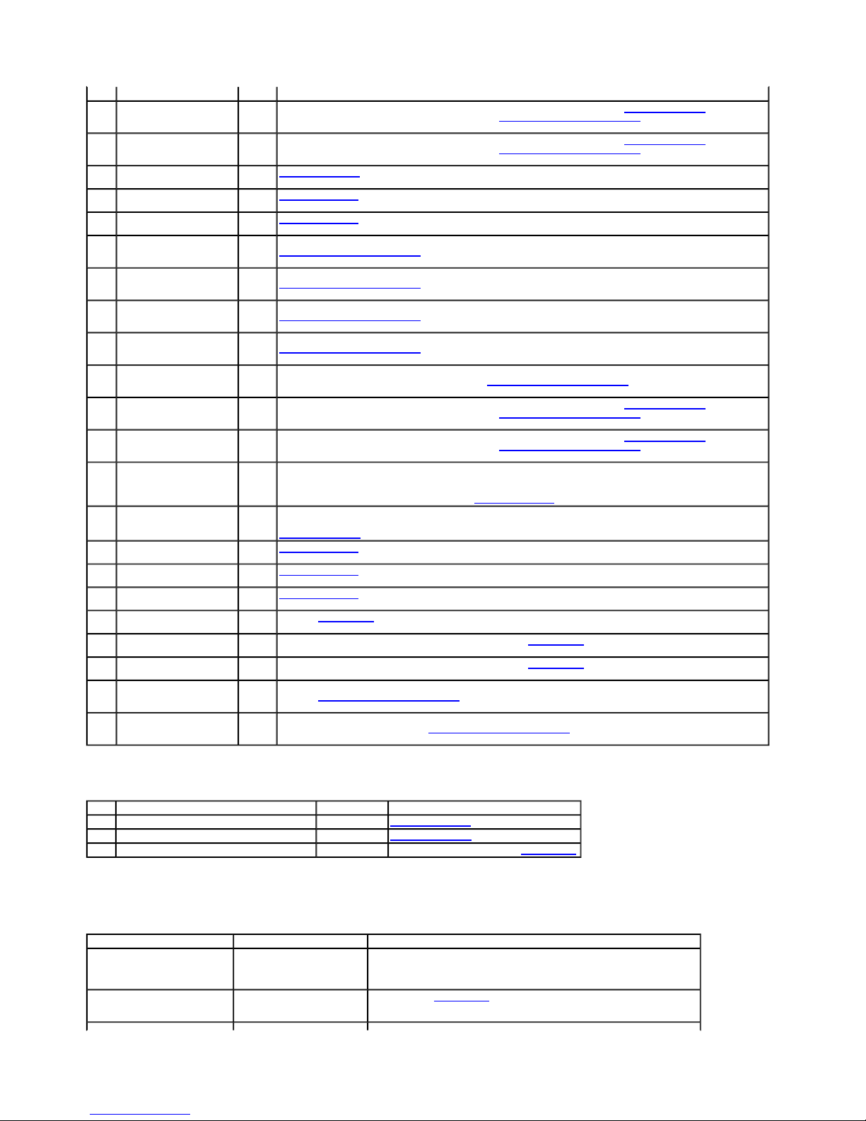
Instrument Cluster DTC Chart
DTC Description Source Action
C1093 Traction Control Disable Switch Circuit Failure Instrument Cluster GO to Pinpoint Test P.
C1105 Traction Control Disable Lamp Circuit Short to Battery Instrument Cluster GO to Pinpoint Test Q.
— All Other instrument cluster DTCs Instrument Cluster REFER to the Master DTC Chart in Section 419-10.
Symptom Chart
Symptom Chart
Condition Possible Sources Action
The red BRAKE warning
indicator and the yellow ABS
warning indicator are both
illuminated
The ABS warning indicator is
never on
DTCs. CARRY OUT the self-test with the brake pedal not applied.
ABS
CLEAR all DTCs. DRIVE the vehicle. RETRIEVE the DTCs. If multiple coil DTCs are retrieved, GO to Pinpoint Test G. If only DTC
Module
C1404 is retrieved, INSTALL a new ABS module. REFER to Anti-Lock Brake System (ABS) Module in this section. Using the scan
tool, CARRY OUT the IVD Initialization sequence. CLEAR the DTCs. CARRY OUT the self-test with the brake pedal not applied.
ABS
CLEAR all DTCs. DRIVE the vehicle. RETRIEVE the DTCs. If multiple coil DTCs are retrieved, GO to Pinpoint Test G. If only DTC
Module
C1410 is retrieved, INSTALL a new ABS module. REFER to Anti-Lock Brake System (ABS) Module in this section. Using the scan
tool, CARRY OUT the IVD Initialization sequence. CLEAR the DTCs. CARRY OUT the self-test with the brake pedal not applied.
ABS
GO to Pinpoint Test N.
Module
GO to Pinpoint Test L.
Module
GO to Pinpoint Test L.
Module
ABS
CLEAR all DTCs. DRIVE the vehicle. RETRIEVE the DTCs. If the DTC is retrieved again, INSTALL a new ABS module. REFER to
Module
Anti-Lock Brake System (ABS) Module in this section. Using the scan tool, CARRY OUT the IVD Initialization sequence. CLEAR the
DTCs. CARRY OUT the self-test with the brake pedal not applied.
ABS
CLEAR all DTCs. DRIVE the vehicle. RETRIEVE the DTCs. If the DTC is retrieved again, INSTALL a new ABS module. REFER to
Module
Anti-Lock Brake System (ABS) Module in this section. Using the scan tool, CARRY OUT the IVD Initialization sequence. CLEAR the
DTCs. CARRY OUT the self-test with the brake pedal not applied.
ABS
CLEAR all DTCs. DRIVE the vehicle. RETRIEVE the DTCs. If the DTC is retrieved again, INSTALL a new ABS module. REFER to
Module
Anti-Lock Brake System (ABS) Module in this section. Using the scan tool, CARRY OUT the IVD Initialization sequence. CLEAR the
DTCs. CARRY OUT the self-test with the brake pedal not applied.
ABS
CLEAR all DTCs. DRIVE the vehicle. RETRIEVE the DTCs. If the DTC is retrieved again, INSTALL a new ABS module. REFER to
Module
Anti-Lock Brake System (ABS) Module in this section. Using the scan tool, CARRY OUT the IVD Initialization sequence. CLEAR the
DTCs. CARRY OUT the self-test with the brake pedal not applied.
ABS
If any other DTCs are present, diagnose those DTCs first. CLEAR all DTCs. DRIVE the vehicle. RETRIEVE DTCs. If the DTC is
Module
retrieved again, INSTALL a new ABS module. REFER to Anti-Lock Brake System (ABS) Module in this section. Using the scan tool,
CARRY OUT the IVD Initialization sequence. CLEAR the DTCs. CARRY OUT the self-test with the brake pedal not applied.
ABS
CLEAR all DTCs. DRIVE the vehicle. RETRIEVE the DTCs. If multiple coil DTCs are retrieved, GO to Pinpoint Test G. If only DTC
Module
C1957 is retrieved, INSTALL a new ABS module. REFER to Anti-Lock Brake System (ABS) Module in this section. Using the scan
tool, CARRY OUT the IVD Initialization sequence. CLEAR the DTCs. CARRY OUT the self-test with the brake pedal not applied.
ABS
CLEAR all DTCs. DRIVE the vehicle. RETRIEVE the DTCs. If multiple coil DTCs are retrieved, GO to Pinpoint Test G. If only DTC
Module
C1958 is retrieved, INSTALL a new ABS module. REFER to Anti-Lock Brake System (ABS) Module in this section. Using the scan
tool, CARRY OUT the IVD Initialization sequence. CLEAR the DTCs. CARRY OUT the self-test with the brake pedal not applied.
NOTE: This DTC will not clear until the vehicle has been driven above 48 km/h (30 mph) with input from the steering wheel rotation
Module
sensor.
REPAIR all other DTCs before repairing DTC C1963. GO to Pinpoint Test K.
NOTE: REPAIR all other DTCs prior to diagnosing this DTC.
Module
GO to Pinpoint Test O.
ABS
GO to Pinpoint Test L.
Module
ABS
GO to Pinpoint Test L.
Module
GO to Pinpoint Test L.
Module
ABS
REFER to Section 418-00 to diagnose the high-speed controller area network (HS-CAN) bus.
Module
ABS
REPAIR all other DTCs first. If DTC U0115 is still present REFER to Section 418-00 to diagnose the HS-CAN bus.
Module
ABS
REPAIR all other DTCs first. If DTC U0155 is still present REFER to Section 418-00 to diagnose the HS-CAN bus.
Module
CLEAR the DTCs. REPEAT the self-test. RETRIEVE the DTCs. If DTC U2050 is retrieved again, INSTALL a new ABS module.
Module
REFER to Anti-Lock Brake System (ABS) Module in this section. Using the scan tool, CARRY OUT the IVD Initialization sequence.
CLEAR the DTC. REPEAT the self-test.
ABS
CLEAR the DTCs. CARRY OUT the ABS module self-test. RETRIEVE and RECORD any DTCs. If DTC U2051 is retrieved again,
Module
INSTALL a new ABS module. REFER to Anti-Lock Brake System (ABS) Module in this section. Using the scan tool, CARRY OUT the
IVD Initialization sequence. CLEAR the DTC. REPEAT the self-test.
DTCs present in the ABS
module
Wiring, terminals or
connectors
Instrument cluster
REFER to the ABS Module DTC Chart in this section.
REFER to Section 413-01 to continue diagnosis of the warning indicator.
Page 6

No communication with the ABS
Page
6
of 62008 E
-
Series Workshop Manual
1/18/2010
http://www.fordtechservice.dealerconnection.com/pubs/content/~WS8M/~MUS~LEN/19/
...
The red BRAKE warning
indicator is always/never on
The stability/traction control
indicator (in the instrument
cluster) is always/never on
The stability/traction control
OFF indicator (in the switch) is
always/never on
The stability/traction control
indicator (in the instrument
cluster) is flashing at all times
module
The stability/traction control
system cannot be
disabled/enabled
The stability/traction control
system is inoperative
ABS false activation, ABS too
sensitive, ABS activates on a
normal stop
Vehicle pulls during braking
Wheels lock up
Soft/excessive brake pedal
travel
Pinpoint Tests
Wiring, terminals or
connectors
Parking brake switch
Brake fluid level switch (part
of the master cylinder)
Brake fluid level
Instrument cluster
DTCs present in the ABS
module or PCM
PCM
Instrument cluster
Wiring, terminals or
connectors
Stability/traction control
switch
PCM
NOTE: It is normal for the
indicator to flash during a
traction control event.
ABS module not configured
or system not initialized
Wiring, terminals or
connectors
ABS module
Fuse
Wiring, terminals or
connectors
Stability/traction control
switch
PCM
Stability/traction control
system is turned off
Stability/traction control
system is not configured
Fuse
Wiring, terminals or
connectors
ABS wheel speed sensor
fault
High-speed controller area
network (HS-CAN) bus fault
PCM
Brake pads
Brake calipers and/or guide
pins
Parking brake shoes out of
adjustment (dragging)
Wheel speed sensor tone
rings
Wheel speed sensor
Chafed wheel speed sensor
wire insulation or pinched
wheel speed sensor wire
Open or shorted wheel
speed sensor circuit
Brake pads
Brake discs
Brake calipers and/or guide
pins
Wheel speed sensor
Brake pads
Brake calipers and/or guide
pins
Parking brake shoes out of
adjustment (dragging)
Hydraulic outlet (dump)
valve
Leaky inlet (isolation) valve
during ABS (soft)
Air in brake system
Brake calipers and/or guide
pins
Brake flexible hose
Brake master cylinder
Brake pads
Brake pedal
Inlet (isolation) valve or
hydraulic outlet (dump)
valve
Leaky inlet (isolation) valve
during ABS applications
(soft)
REFER to Section 413-01 to continue diagnosis of the warning indicator.
RETRIEVE and RECORD any ABS module DTCs. GO to the ABS Module DTC
Chart. If there are no DTCs present in the ABS module, RETRIEVE and RECORD
any PCM DTCs. REFER to the Powertrain Control/Emissions Diagnosis (PC/ED)
manual. If there are no PCM DTCs, REFER to Diagnosis and Testing in Section
413-01.
GO to Pinpoint Test Q.
RETRIEVE and RECORD all ABS module DTCs and GO to the ABS Module DTC
Chart.
REFER to Section 418-00 to diagnose the no communication concern.
GO to Pinpoint Test P.
GO to Pinpoint Test P.
ELIMINATE the base brake system as the cause of the problem. REFER to
Diagnosis and Testing in Section 206-00.
CHECK and if necessary, ADJUST the parking brake shoes. REFER to Section
206-05.
INSPECT the wheel speed sensor tone rings for damaged teeth and excessive air
gap. INSTALL new wheel speed sensor rings as necessary. For front tone rings,
REFER to Wheel Speed Sensor Ring — Front in this section. For rear tone rings,
REFER to Wheel Hub Removal and Installation in Section 205-02B.
GO to Pinpoint Test J.
INSPECT the wiring harness from the wheel speed sensor knuckle to the frame
and from the rear axle to the frame. REPAIR as necessary.
GO to Pinpoint Test I.
DISCONNECT the ABS module electrical connector. DRIVE the vehicle and
VERIFY the condition. If the condition is still present, REFER to Section 206-00 to
diagnose the base braking system. If the condition is no longer present, GO to
Pinpoint Test J.
ELIMINATE the base brake system as the cause of the problem. REFER to
Diagnosis and Testing in Section 206-00.
CHECK and if necessary, ADJUST the parking brake shoes. REFER to Section
206-05.
BLEED the HCU. REFER to Brake System Bleeding in Section 206-00. TEST the
system for normal operation. If the symptom returns, INSTALL a new HCU. REFER
to Hydraulic Control Unit (HCU) in this section. Using the scan tool, CARRY OUT
the IVD Initialization sequence. TEST the system for normal operation.
ELIMINATE the base brake system as the cause of the problem. REFER to
Diagnosis and Testing in Section 206-00.
BLEED the hydraulic control unit (HCU). REFER to Brake System Bleeding in
Section 206-00. TEST the system for normal operation. If the symptom returns,
INSTALL a new HCU. REFER to Hydraulic Control Unit (HCU) in this section.
Using the scan tool, CARRY OUT the IVD Initialization sequence. TEST the system
for normal operation.
 Loading...