

Page 1

Contents
Before driving
Introduction 2
Instrumentation 3
Controls and features 14
Seating and safety restraints 61
Starting and driving
Starting 83
Driving 89
Roadside emergencies 105
Servicing
Maintenance and care 123
Capacities and specifications 174
Customer assistance 181
Reporting safety defects 193
Index 194
All rights reserved. Reproduction by any means, electronic or mechanical
including photocopying, recording or by any information storage and retrieval
system or translation in whole or part is not permitted without written
authorization from Ford Motor Company.
Copyrightr1998 Ford Motor Company
1
Page 2
Introduction
ICONS
Indicates a safety alert. Read the
following section on Warnings.
Indicates vehicle information related
to recycling and other
environmental concerns will follow.
Correct vehicle usage and the
authorized disposal of waste
cleaning and lubrication materials are significant steps towards
protecting the environment.
Indicates a message regarding child
safety restraints. Refer to Seating
and safety restraints for more
information.
Indicates that this Owner Guide
contains information on this subject.
Please refer to the Index to locate
the appropriate section which will
provide you more information.
WARNINGS
Warnings provide information which may reduce the risk of personal
injury and prevent possible damage to others, your vehicle and its
equipment.
BREAKING-IN YOUR VEHICLE
There are no particular breaking-in rules for your vehicle. During the
first 1 600 km (1 000 miles) of driving, vary speeds frequently. This is
necessary to give the moving parts a chance to break in.
INFORMATION ABOUT THIS GUIDE
The information found in this guide was in effect at the time of printing.
Ford may change the contents without notice and without incurring
obligation.
2
Page 3

Instrumentation
3
Page 4
Instrumentation
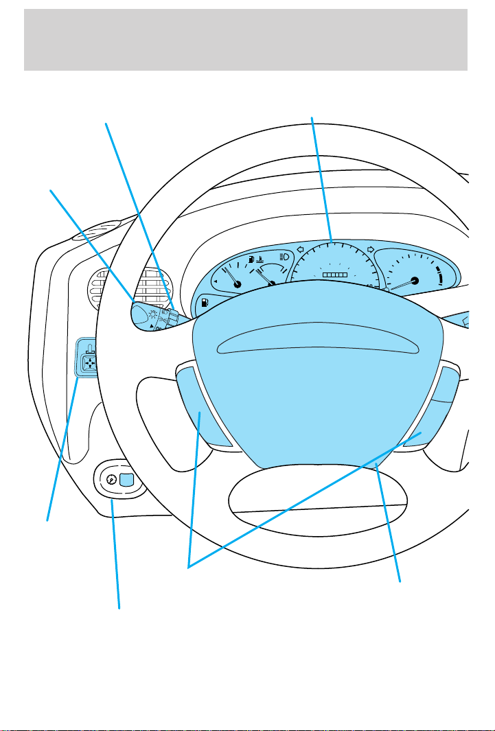
Foglamp control *
Headlamp
control
(pg. 42)
(pg. 44)
MIRROR
L
FUEL
FILL
LOW
FUEL
1
/
2
EF
Instrument cluster
(pg. 6)
50
40
80
60
30
CH
60 70
100
000113
80
120
THEFT
4
90
140
160
100
5
6
3
RPMx1000
2
7
1
8
Power side
view mirrors*
(pg. 14)
*if equipped
4
Instrument panel
dimmer switch
(pg. 14)
Speed control*
(pg. 44)
Driver side air bag
(pg. 71)
Page 5
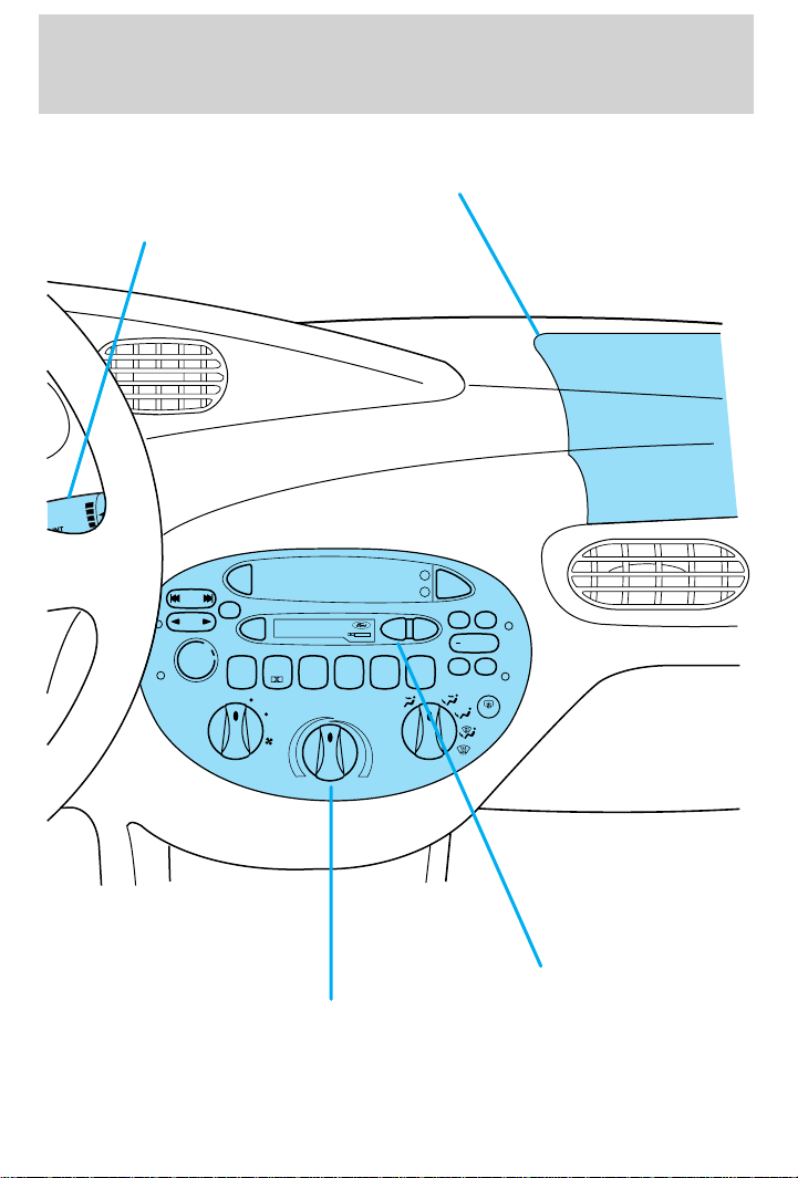
Windshield wiper/
washer control
(pg. 49)
F
IN
MIST
OFF
Instrumentation
Passenger side air bag
(pg. 71)
SEEK
TRACK
TUNE
DISCS
AM
FM
SCAN
VOL
PUSH ON
PREMIUM SOUND
EJ
23456
1
SIDE 1-2
LO
HI
Climate control system
(pg. 37)
H
TAPE
CD
M
BASS
REW
DOLBYB NR
COMP
SHUF
A/C
MAX
A/C
TREB
FF
+
BAL
FADE
OFF
R.DEF
Electronic sound system
(pg. 15)
5
Page 6
Instrumentation
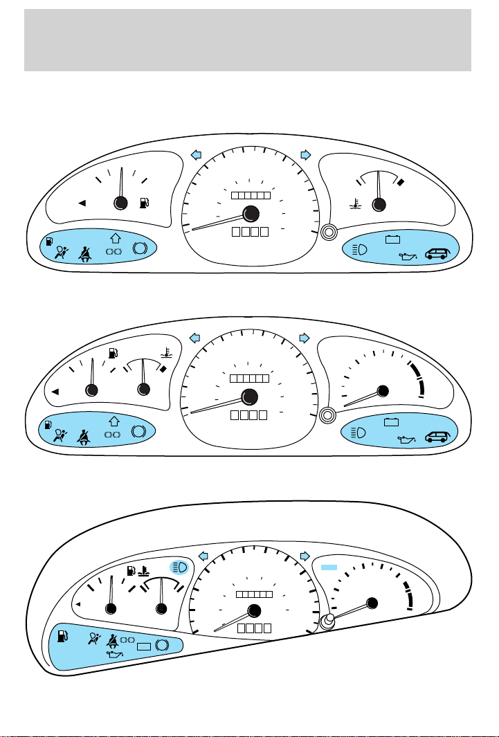
WARNING LIGHTS AND CHIMES
Base instrument cluster
50
10
10
20
20
30
30
40
40
20
40
20
km/h
40
MPH
km/h
MPH
60
50
60
1
/
2
EF
FUEL FILL
SERVICE
ENGINE
LOW
FUEL
SOON
P
BRAKE
ABS
!
Sport instrument cluster
1
/
2
CH
!
P
BRAKE
ABS
LOW
FUEL
FUEL FILL
SERVICE
ENGINE
SOON
EF
60
70
100
80
0000000
0 0 0
60
70
100
120
80
0000000
0 0 0
80
120
90
140
100
160
110
180
200
120
CH
+–
THEFT
80
90
140
100
160
110
180
200
120
4
5
6
3
RPMx1000
2
1
7
8
+–
THEFT
ZX2 coupe instrument cluster
40
30
20
10
FUEL
FILL
LOW
FUEL
SERVICE
ENGINE
SOON
1
/
2
EF
!
P
BRAKE
CH
+–
ABS
6
40
60
20
50
80
MPH
60 70
120
100
0000000
0 0 0
km/h
80
140
THEFT
4
90
160
100
180
110
5
6
3
RPMx1000
2
1
7
8
120
Page 7
Instrumentation
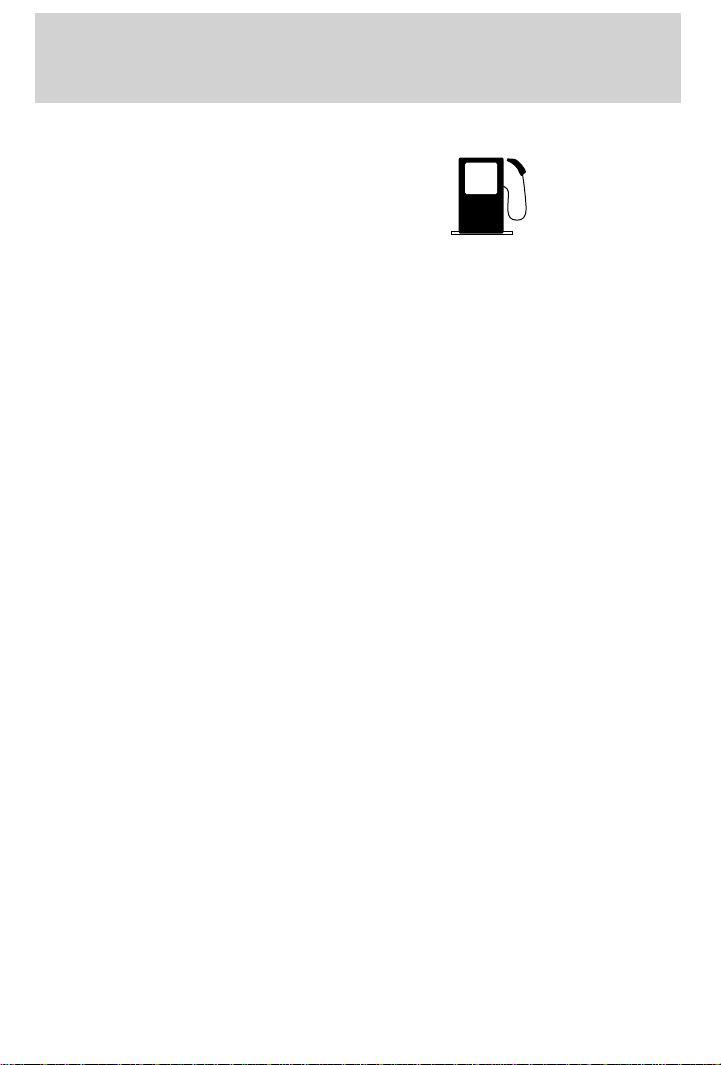
Low fuel
Illuminates as an early reminder of a
low fuel condition indicated on the
fuel gauge. The light comes on when
there is approximately 1/16th of a
tank indicated on the fuel gauge
(refer to Fuel gauge in this chapter for more information). The ignition
must be in the ON position for this lamp to illuminate. The lamp will also
illuminate for several seconds after the ignition is turned to the ON
position regardless of the fuel level.
Service engine soon
Your vehicle is equipped with a
computer that monitors the engine’s
emission control system. This
system is commonly known as the
On Board Diagnostics System (OBD
II). The OBD II system protects the
environment by ensuring that your vehicle continues to meet
government emission standards. The OBD II system also assists the
service technician in properly servicing your vehicle.
The Service Engine Soon indicator light illuminates when the ignition is
first turned to the ON position to check the bulb. If it comes on after the
engine is started, one of the engine’s emission control systems may be
malfunctioning. The light may illuminate without a driveability concern being
noted. The vehicle will usually be drivable and will not require towing.
What you should do if the Service Engine Soon light illuminates
Light turns on solid:
This means that the OBD II system has detected a malfunction.
Temporary malfunctions may cause your Service Engine Soon light to
illuminate. Examples are:
1.
The vehicle has run out of fuel. (The engine may misfire or run poorly.)
2. Poor fuel quality or water in the fuel.
3. The fuel cap may not have been properly installed and securely
tightened.
These temporary malfunctions can be corrected by filling the fuel tank
with good quality fuel and/or properly installing and securely tightening
the gas cap. After three driving cycles without these or any other
LOW
FUEL
SERVICE
ENGINE
SOON
7
Page 8
Instrumentation
temporary malfunctions present, the Service Engine Soon light should
turn off. (A driving cycle consists of a cold engine startup followed by
mixed city/highway driving.) No additional vehicle service is required.
If the Service Engine Soon light remains on, have your vehicle serviced
at the first available opportunity.
Light is blinking:
Engine misfire is occurring which could damage your catalytic converter.
You should drive in a moderate fashion (avoid heavy acceleration and
deceleration) and have your vehicle serviced at the first available
opportunity.
Under engine misfire conditions, excessive exhaust temperatures
could damage the catalytic converter, the fuel system, interior
floor coverings or other vehicle components, possibly causing a fire.
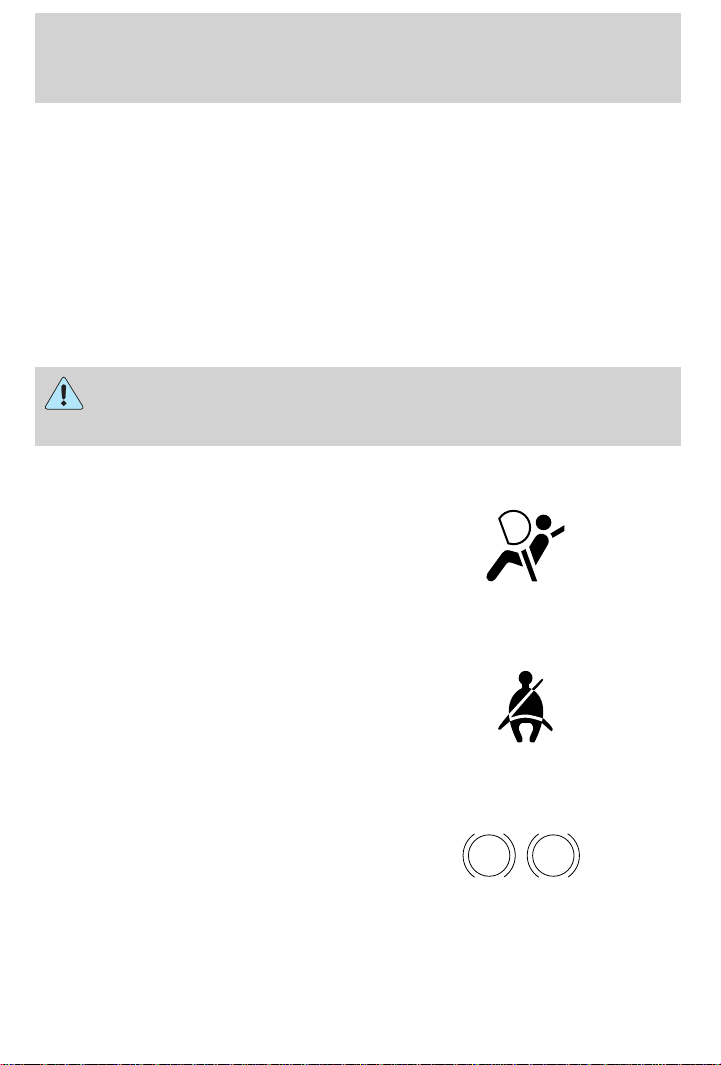
Air bag readiness
Momentarily illuminates when the
ignition is turned ON. If the light
fails to illuminate, continues to flash
or remains on, have the system
serviced immediately.
Safety belt
Momentarily illuminates when the
ignition is turned to the ON position
to remind you to fasten your safety
belts. For more information, refer to
the Seating and safety restraints
chapter.
Brake system warning
Momentarily illuminates when the
ignition is turned to the ON
position, the engine is off and the
parking brake is engaged. If the
brake warning lamp does not
illuminate at this time, seek service immediately. Illumination after
releasing the parking brake indicates low brake fluid level and the brake
system should be inspected immediately.
8
P !
BRAKE
Page 9
Instrumentation
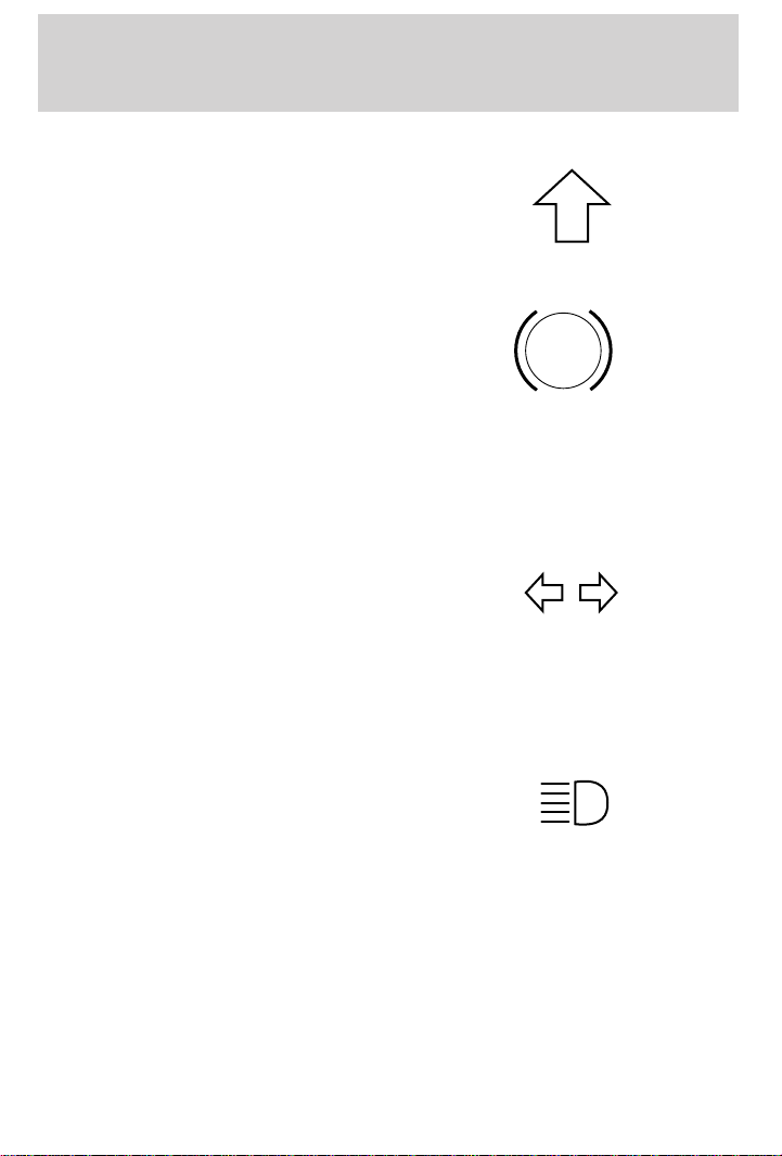
Shift indicator light (if equipped)
To maximize fuel economy, the shift
indicator light illuminates when the
manual transmission should be
shifted to the next highest gear.
Anti-lock brake system (ABS) (If equipped)
Momentarily illuminates when the
ignition is turned on and the engine
is off. If the light does not illuminate
momentarily at start up, remains on
or continues to flash, the ABS needs
to be serviced. With the ABS light on, the anti-lock brake system is
disabled and normal braking is still effective unless the brake warning
light also remains illuminated with parking brake released.
Turn signal
Illuminates when the left or right
turn signal or the hazard lights are
turned on. If one or both of the
indicators stay on continuously or
flash faster, check for a burned-out
turn signal bulb. Refer to Exterior bulbs in the Maintenance and care
chapter.
ABS
High beams
Illuminates when the high beam
headlamps are turned on.
Anti-theft system (if equipped)
Refer to SecuriLocky passive
anti-theft system in the Controls
and features chapter.
THEFT
9
Page 10
Instrumentation
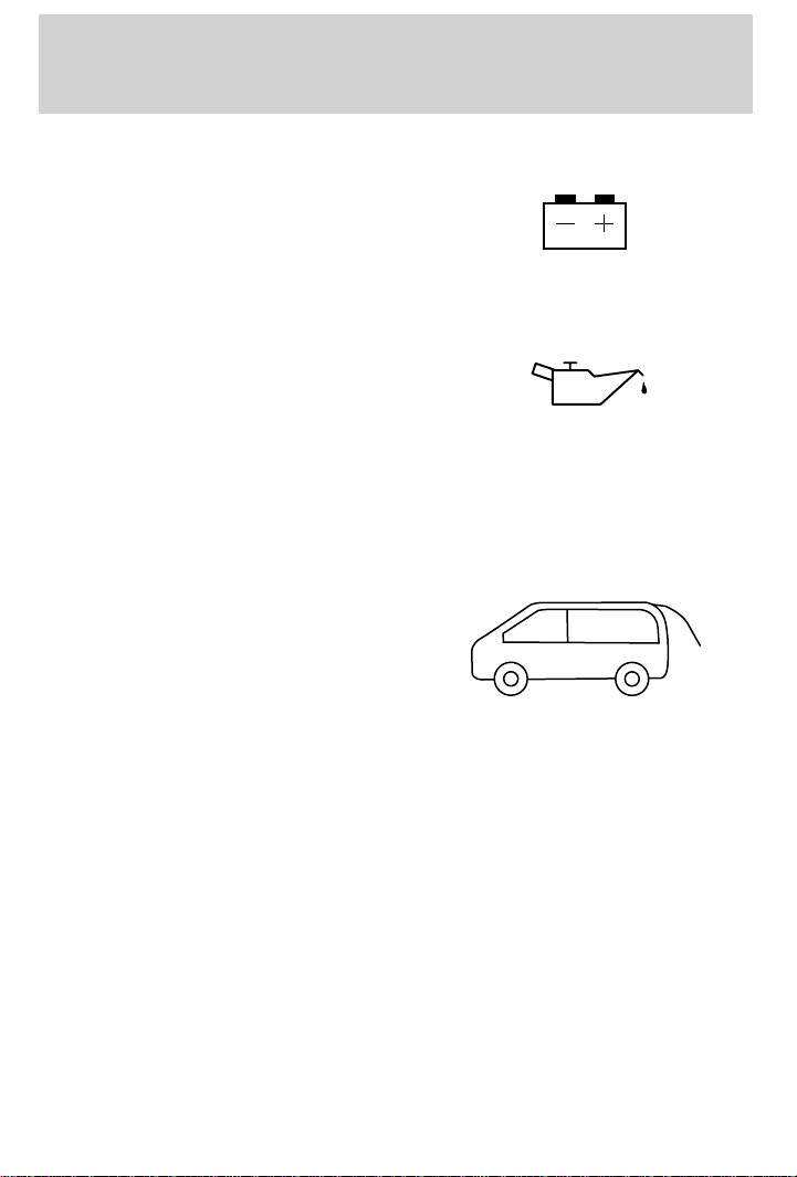
Charging system
Illuminates when the ignition is
turned to the ON position and the
engine is off. The light also
illuminates when the battery is not
charging properly, requiring
electrical system service.
Engine oil pressure
Momentarily illuminates when the
ignition is turned to the ON position
and the engine is off. Illuminates
when the oil pressure falls below the
normal range. Stop the vehicle as
soon as safely possible and switch off the engine immediately. Check the
oil level and add oil if needed. Refer to Engine oil in the Maintenance
and Care chapter.
Liftgate ajar (if equipped)
Illuminates when the ignition is in
the ON position and the liftgate is
open.
Safety belt warning chime
Chimes to remind you to fasten your safety belts.
For information on the safety belt warning chime, refer to the Seating
and safety restraints chapter.
Supplemental restraint system (SRS) warning chime
For information on the SRS warning chime, refer to the Seating and
safety restraints chapter.
Key-in-ignition warning chime
Sounds when the key is left in the ignition in the OFF/LOCK or ACC
position and the driver’s door is opened.
Headlamps on warning chime
Sounds when the headlamps or parking lamps are on, the ignition is off
(and the key is not in the ignition) and the driver’s door is opened.
10
Page 11
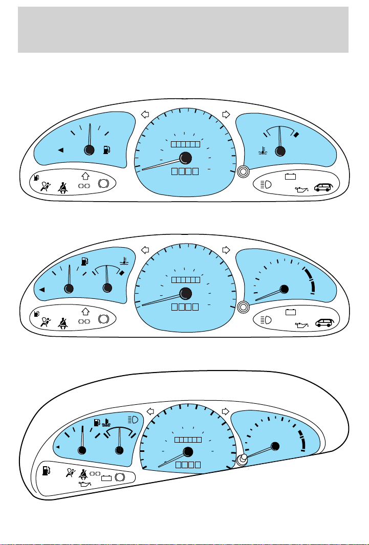
GAUGES
Base instrument cluster gauges
50
10
20
30
40
40
20
MPH
km/h
60
1
/
2
EF
FUEL FILL
SERVICE
ENGINE
LOW
FUEL
SOON
P
BRAKE
ABS
!
Sport instrument cluster gauges
50
10
20
30
40
40
20
MPH
km/h
60
LOW
FUEL
FUEL FILL
SERVICE
ENGINE
SOON
1
/
2
EF
!
P
BRAKE
CH
ABS
60
100
80
0000000
0 0 0
60
100
80
0000000
0 0 0
70
70
Instrumentation
80
120
90
140
100
160
110
180
200
120
80
120
90
140
100
160
110
180
200
120
CH
THEFT
4
5
3
RPMx1000
2
1
THEFT
+–
6
7
8
+–
ZX2 coupe instrument cluster gauges
60 70
50
120
100
40
80
60
30
0000000
40
20
20
MPH
0 00
10
FUEL
FILL
LOW
FUEL
SERVICE
ENGINE
SOON
1
/
2
EF
!P
BRAKE
CH
+–
ABS
km/h
80
140
THEFT
4
90
160
100
180
110
5
6
3
RPMx1000
2
1
7
8
120
11
Page 12
Instrumentation
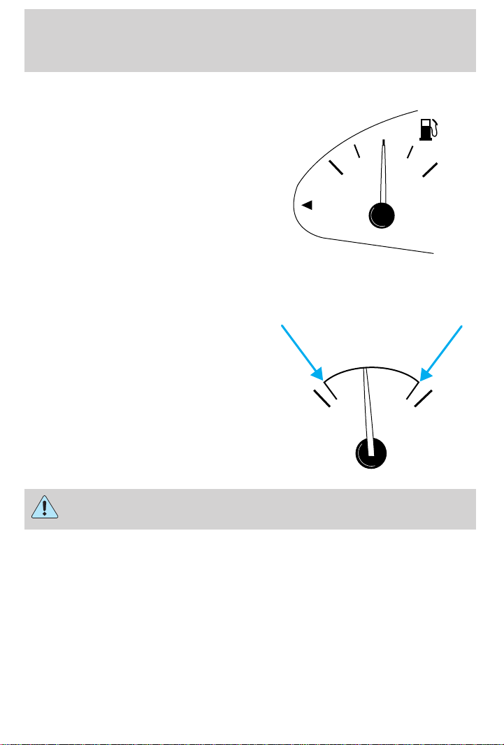
Fuel gauge
Displays approximately how much
fuel is in the fuel tank (when the
key is in the ON position). The fuel
gauge may vary slightly when the
vehicle is in motion. The ignition
should be in the OFF position while
the vehicle is being refueled. When
the gauge first indicates empty,
there is a small amount of reserve
fuel in the tank. When refueling the
vehicle from empty indication, the
amount of fuel that can be added will be less than the advertised
capacity due to the reserve fuel.
Engine coolant temperature gauge
Indicates the temperature of the
engine coolant. At normal operating
temperature, the needle remains
within the normal area (the area
between the “H” and “C”). If it enters
the red section, the engine is
overheating. Stop the vehicle as soon
as safely possible, switch off the
engine immediately and let the engine
cool. Refer to Engine coolant in the
Maintenance and care chapter.
FUEL
FILL
CH
1
/
2
EF
Never remove the coolant reservoir cap while the engine is
running or hot.
This gauge indicates the temperature of the engine coolant, not the
coolant level. If the coolant is not at its proper level the gauge indication
will not be accurate.
12
Page 13
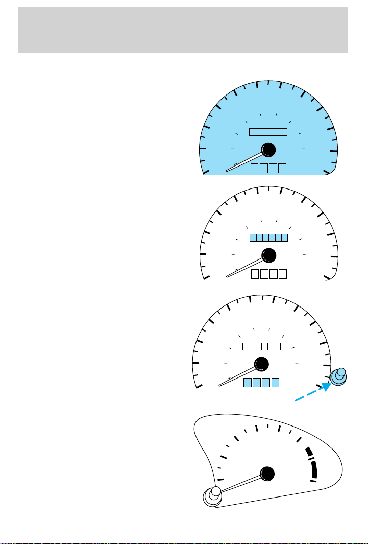
Speedometer
Indicates the current vehicle speed.
Odometer
Registers the total kilometers
(miles) of the vehicle.
Trip odometer
Registers the kilometers (miles) of
individual journeys. To reset,
depress the control.
20
30
10
20
20
Instrumentation
60 70
50
20
20
50
MPH
60
MPH
50
60
MPH
80
100
80
0000000
0 00
60 70
100
80
0 00000
0
0 00
60 70
120
100
0 00000
0000
40
30
40
10
40
30
40
10
40
60
40
20
120
120
80
140
km/h
80
140
km/h
140
km/h
80
160
160
160
90
100
180
120
90
100
180
120
90
100
180
120
110
110
110
Tachometer (if equipped)
Indicates the engine speed in
revolutions per minute.
Driving with your tachometer
pointer in the red zone may damage
the engine.
THEFT
1
2
3
4
5
RPMx1000
6
7
8
13
Page 14
Controls and features
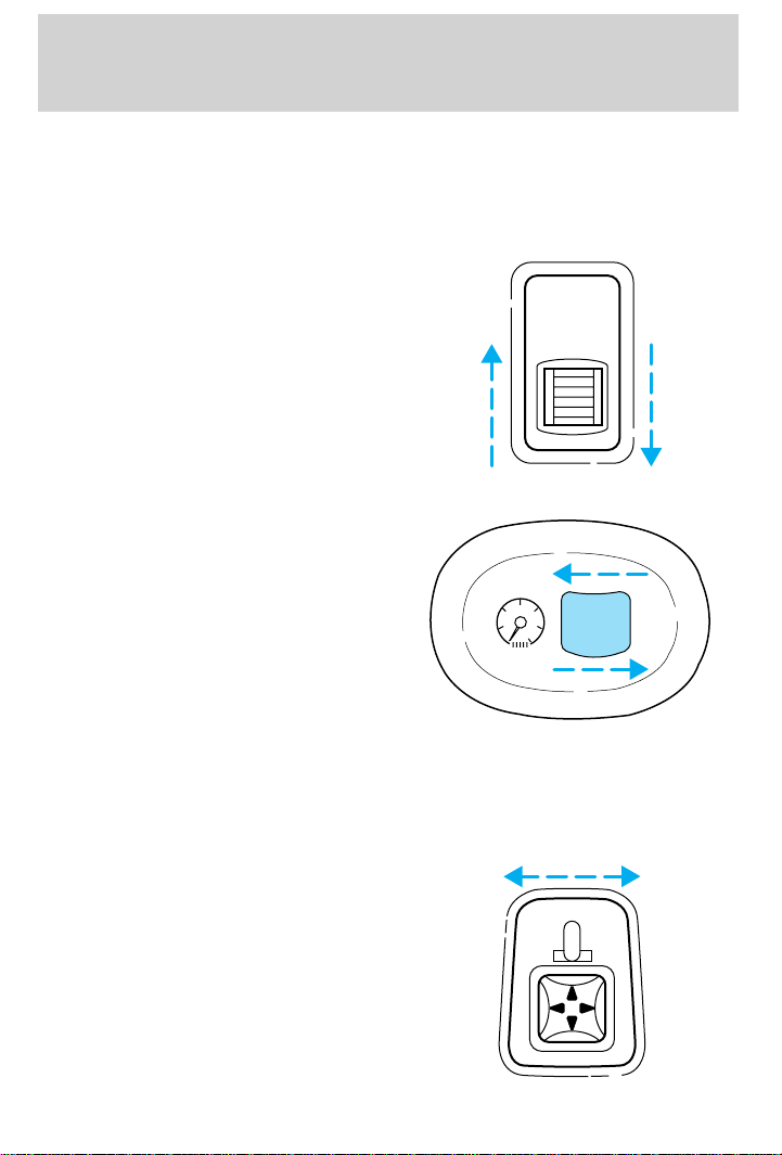
PANEL DIMMER CONTROL
Use to adjust the brightness of the instrument panel during headlamp
and parklamp operation.
Coupe
• Rotate up to brighten.
• Rotate down to dim.
Sedan/Wagon
• Rotate left to brighten.
• Rotate right to dim.
POWER SIDE VIEW MIRRORS (IF EQUIPPED)
The ignition must be in ACC or ON position to adjust the power side
view mirrors.
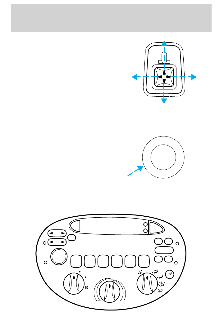
To adjust your mirrors:
1. Select L to adjust the left mirror
or R to adjust the right mirror.
14
MIRRORS
L R
Page 15
Controls and features
2. Move the control in the direction
you wish to tilt the mirror.
3. Return to the center position to lock mirrors in place.
TRUNK REMOTE CONTROL
Press the remote trunk release
control on the instrument panel to
open the trunk.
USING YOUR AUDIO SYSTEM
AM/FM stereo
MIRRORS
L R
R
K
N
U
R
T
E
S
A
L
E
E
A
S
E
T
R
U
N
K
R
E
E
L
SEEK
TUNE
AM
SCAN
VOL
PUSH ON
123456
LO
A/C
HI
MAX
A/C
H
FM
M
BASS
TREB
+
BAL
FADE
OFF
R.DEF
15
Page 16
Controls and features
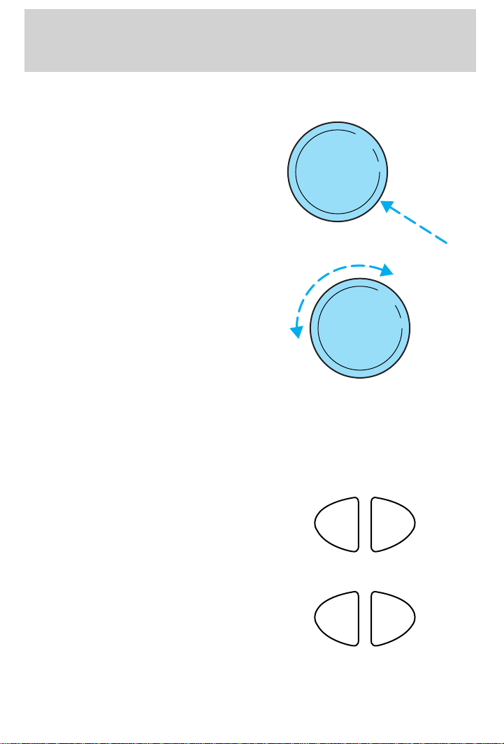
Volume/power control
Press the control to turn the audio
system on or off.
VOL
PUSH ON
Turn control to raise or lower
volume.
VOL
PUSH ON
If the volume is set above a certain level and the ignition is turned off,
the volume will come back on at a “nominal” listening level when the
ignition switch is turned back on. If you wish to maintain your preset
volume level, turn the audio system off with the power control before
switching off the ignition.
AM/FM select
The AM/FM select control works in
radio mode.
AM
FM
AM/FM select in radio mode
This control allows you to select AM
or FM frequency bands. Press the
control to switch between AM, FM1
or FM2 memory preset stations.
AM
FM
16
Page 17
Tune adjust
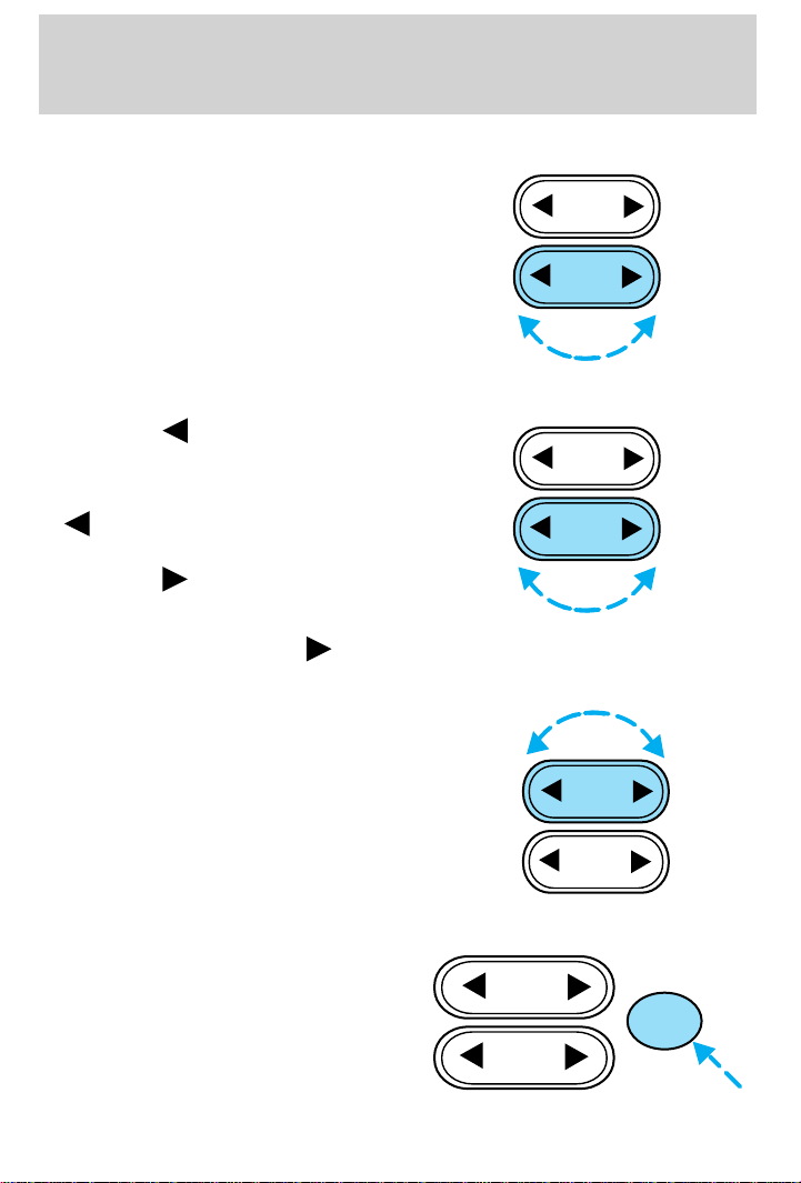
The tune control works in radio
mode.
Tune adjust in radio mode
• Press the to move to the next
frequency down the band
(whether or not a listenable
station is located there). Hold the
to move through the
frequencies quickly.
• Press the to move to the next
frequency up the band (whether
or not a listenable station is
located there). Hold the
for quick movement.
Seek function
The seek function control works in
radio mode.
Controls and features
SEEK
TUNE
SEEK
TUNE
Scan function
The scan function works in radio
mode.
SEEK
TUNE
SEEK
SCAN
TUNE
17
Page 18
Controls and features
Scan function in radio mode
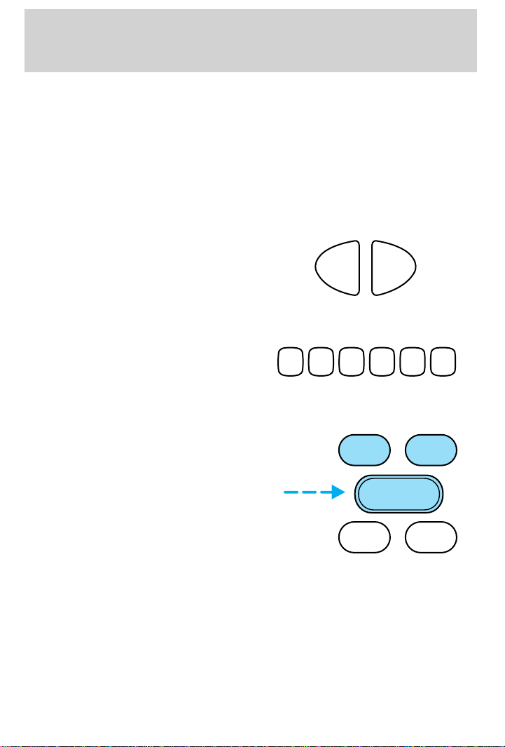
Press the SCAN control to hear a brief sampling of all listenable stations
on the frequency band. Press the control again to stop the scan mode.
Radio station memory preset
The radio is equipped with six station memory preset controls. These
controls can be used to select up to six preset AM stations and twelve
FM stations (six in FM1 and six in FM2).
Setting memory preset stations
1. Select the frequency band with
the AM/FM select control.
2. Select a station. Refer to Tune adjust or Seek function for more
information on selecting a station.
3. Press and hold a memory preset
control until the sound returns,
123456
indicating the station is held in
memory on the control you selected.
Bass/treble adjust
• The bass adjust control allows
you to increase or decrease the
audio system’s bass output.
• The treble adjust control allows
you to increase or decrease the
audio system’s treble output.
AM
FM
BASS TREB
–+
BAL
FADE
18
Page 19
Controls and features
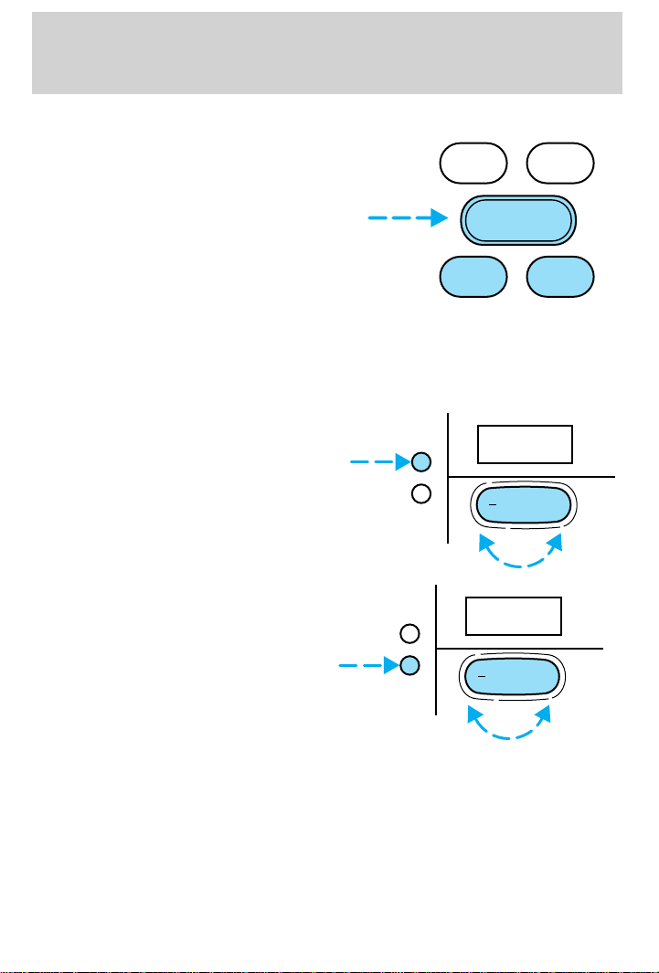
Speaker balance/fade adjust
• Speaker sound distribution can be
adjusted between the right and
left speakers.
• Press the BAL control. Toggle
between the + and — control to
adjust the speaker sound.
• Speaker sound can be adjusted
between the front and rear
speakers.
• Press the FADE control. Toggle between the + and — control to
adjust the speaker sound.
Setting the clock
To set the hour, press the hour (h)
control and press:
• (+) to increase hour and
• (−) to decrease hour
To set the minute, press the minute
(m) control and press:
• (+) to increase minutes and
• (−) to decrease minutes
BASS TREB
–+
BAL
H
M
H
M
:01
FADE
12:
+
+
19
Page 20
Controls and features
AM/FM Stereo/Cassette
AM
SCAN
VOL
PUSH ON
SIDE 1-2
LO
FM
EJ
1
23456
HI
SEEK
TUNE
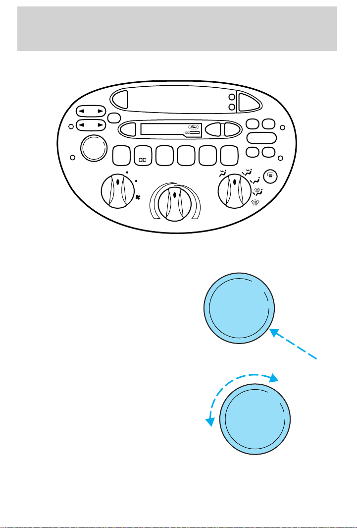
Volume/power control
Press the control to turn the audio
system on or off.
Turn control to raise or lower
volume.
DOLBY B NR
MAX
REW
A/C
H
TAPE
M
BASS
FF
OFF
A/C
TREB
+
BAL
FADE
R.DEF
VOL
PUSH ON
VOL
PUSH ON
If the volume is set above a certain level and the ignition is turned off,
the volume will come back on at a “nominal” listening level when the
ignition switch is turned back on. If you wish to maintain your preset
20
Page 21
Controls and features
volume level, turn the audio system off with the power control before
switching off the ignition.
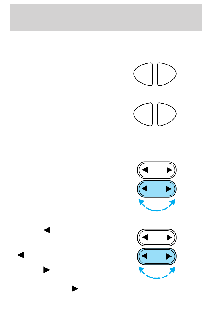
AM/FM select
The AM/FM select control works in
radio modes.
AM/FM select in radio mode
This control allows you to select AM
or FM frequency bands. Press the
control to switch between AM, FM1
or FM2 memory preset stations.
AM/FM select in tape mode
Press this control to stop tape play and begin radio play.
Tune adjust
The tune control works in radio
mode.
AM
AM
FM
FM
SEEK
TUNE
Tune adjust in radio mode
• Press the to move to the next
frequency down the band
(whether or not a listenable
station is located there). Hold the
to move through the
frequencies quickly.
• Press the to move to the next
frequency up the band (whether
or not a listenable station is
located there). Hold
for quick movement.
SEEK
TUNE
21
Page 22
Controls and features
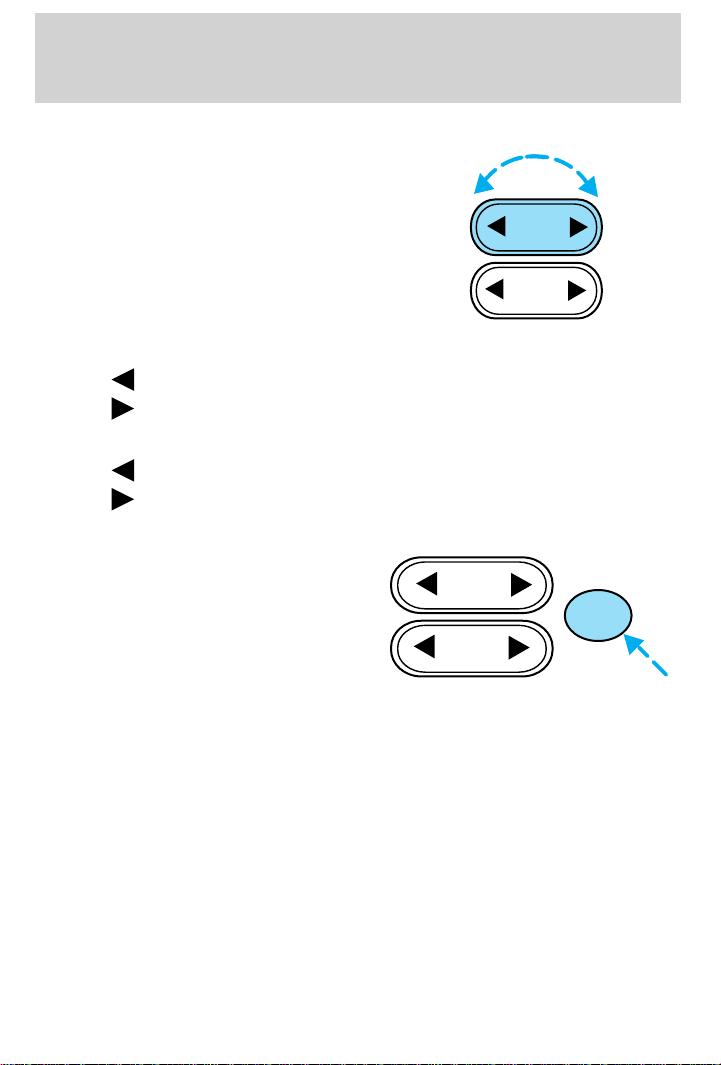
Seek function
The seek function control works in
radio or tape mode.
SEEK
TUNE
Seek function in radio mode
• Press to find the next listenable station down the frequency band.
• Press
Seek function in tape mode
• Press to listen to the previous selection on the tape.
• Press
Scan function
The scan function works in radio or
tape mode.
to find the next listenable station up the frequency band.
to listen to the next selection on the tape.
SEEK
SCAN
TUNE
Scan function in radio mode
Press the SCAN control to hear a brief sampling of all listenable stations
on the frequency band. Press the control again to stop the scan mode.
Scan function in tape mode
Press the SCAN control to hear a short sampling of all selections on the
tape. (The tape scans in a forward direction. At the end of the tape’s
first side, direction automatically reverses to the opposite side of the
tape.) To stop on a particular selection, press the control again.
Radio station memory preset
The radio is equipped with six station memory preset controls. These
controls can be used to select up to six preset AM stations and twelve
FM stations (six in FM1 and six in FM2).
22
Page 23
Controls and features
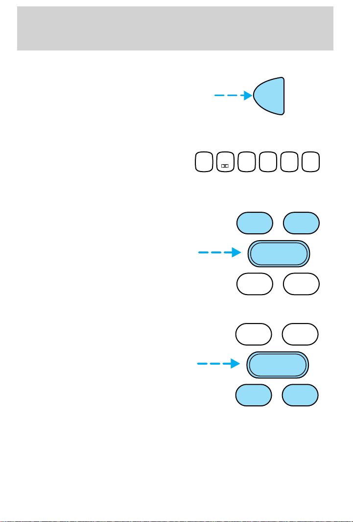
Setting memory preset stations
1. Select the frequency band with
the AM/FM select control.
2. Select a station. Refer to Tune adjust or Seek function for more
information on selecting a station.
3. Press and hold a memory preset
control until the sound returns,
1
23456
SIDE 1-2
indicating the station is held in
memory on the control you selected.
Bass/treble adjust
• The bass adjust control allows
you to increase or decrease the
audio system’s bass output.
• The treble adjust control allows
you to increase or decrease the
audio system’s treble output.
Speaker balance/fade adjust
• Speaker sound distribution can be
adjusted between the right and
left speakers.
• Press the BAL control. Toggle
between the + and — control to
adjust the speaker sound.
• Speaker sound can be adjusted
between the front and rear
speakers.
• Press the FADE control. Toggle between the + and — control to
adjust the speaker sound.
AM
FM
BASS TREB
–+
BAL
BASS TREB
–+
BAL
FADE
FADE
23
Page 24
Controls and features
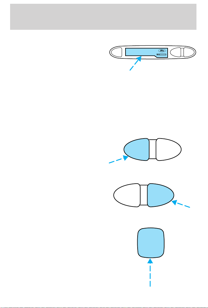
Inserting a tape
Push only slightly when inserting a
cassette tape (with the open edge
EJ
DOLBY B NR
REW
FF
to the right). A cassette deck
loading mechanism pulls the tape in
the rest of the way.
You can switch from radio to tape play by inserting a tape into the
cassette deck.
Tape play select
Insert a tape to begin tape play.
Push only slightly when inserting a cassette tape (with the open edge to
the right). A cassette deck loading mechanism pulls the tape in the rest
of the way.
Rewind
The rewind control works in tape mode.
• In tape mode, radio play will
REW
FF
continue until rewind is stopped
(with the TAPE control) or the
beginning of the tape is reached.
Fast forward
The fast forward control works in
tape mode.
• In the tape mode, tape direction
REW
FF
will automatically reverse when
the end of the tape is reached.
Tape side select
Press this control to play the
alternate side of a tape.
1
SIDE 1-2
24
Page 25
Eject function
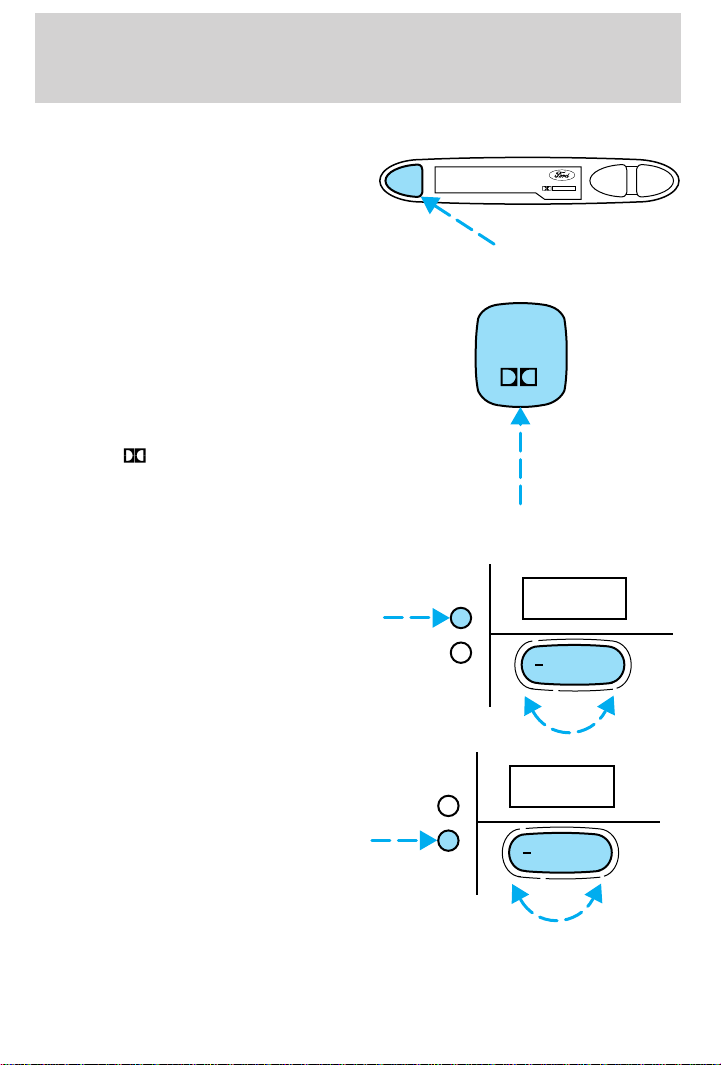
Press the control to stop and eject a
tape.
DolbyTnoise reduction
Dolbyt noise reduction
manufactured under license from
Dolby Laboratories Licensing
Corporation operates only in tape
mode. Dolbyt reduces the amount
of hiss and static during tape
playback.
Press the
button to activate (and
deactivate) Dolbyt noise reduction.
Setting the clock
To set the hour, press the hour (h)
control and press:
• (+) to increase hour and
• (−) to decrease hour
Controls and features
EJ
DOLBY B NR
REW
FF
2
H
M
12:
+
To set the minute, press the minute
(m) control and press:
• (+) to increase minutes and
• (−) to decrease minutes
H
M
:01
+
25
Page 26
Controls and features
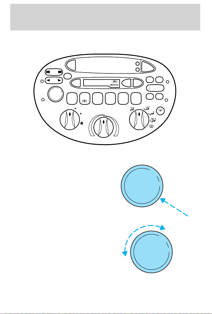
Premium AM/FM Stereo/Cassette/ Premium Sound
(Radio Controlled CD Changer Compatible)
AM
SCAN
VOL
PUSH ON
SIDE 1-2
LO
FM
PREMIUM SOUND
EJ
1
23456
HI
SEEK
TRACK
TUNE
DISCS
Volume/power control
Press the control to turn the audio
system on or off.
Turn control to raise or lower
volume.
DOLBY B NR
COMP
MAX
A/C
REW
H
TAPE
CD
M
BASS
FF
SHUF
OFF
A/C
TREB
+
BAL
FADE
R.DEF
VOL
PUSH ON
VOL
PUSH ON
If the volume is set above a certain level and the ignition is turned off,
the volume will come back on at a “nominal” listening level when the
26
Page 27
Controls and features
ignition switch is turned back on. If you wish to maintain your preset
volume level, turn the audio system off with the power control before
switching off the ignition.
AM/FM select
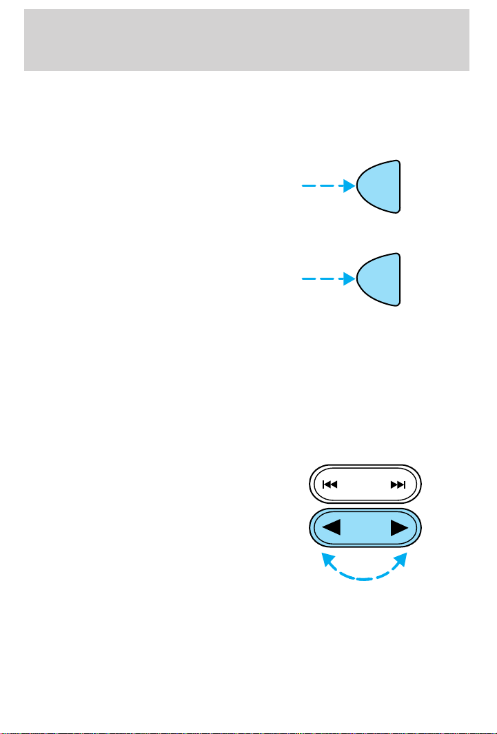
The AM/FM select control works in
radio, tape and CD modes (if
equipped).
AM/FM select in radio mode
This control allows you to select AM
or FM frequency bands. Press the
control to switch between AM, FM1
or FM2 memory preset stations.
AM/FM select in tape mode
Press this control to stop tape play and begin radio play.
AM/FM select in CD mode
Press this control to stop CD play and begin radio play.
You can switch from CD play to tape play by simply inserting a tape into
the cassette deck.
Tune adjust
The tune control works in radio or
CD mode (if equipped).
AM
FM
AM
FM
SEEK
TRACK
TUNE
DISCS
27
Page 28
Controls and features
Tune adjust in radio mode
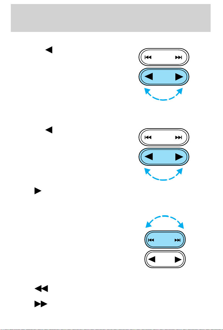
• Press the to move to the next
frequency down the band
(whether or not a listenable
station is located there). Hold the
control to move through the
frequencies quickly.
• Press the right side of the control
to move to the next frequency up
the band (whether or not a
listenable station is located there). Hold for quick movement.
Tune adjust for CD mode (if equipped)
• Press the to select the
previous disc in the CD changer.
(Play will begin on the first track
of the disc unless the CD changer
is in shuffle mode. Refer to
Shuffle feature for more
information. Hold the control to
continue reversing through the
disc.
• Press
to select the next disc in the CD changer. Hold the control
to fast-forward through the remaining discs.
Seek function
The seek function control works in
radio, tape or CD mode (if
equipped).
SEEK
TRACK
TUNE
DISCS
SEEK
TRACK
TUNE
DISCS
SEEK
TRACK
TUNE
DISCS
Seek function in radio mode
• Press to find the next listenable station down the frequency
band.
• Press to find the next listenable station up the frequency band.
28
Page 29
Controls and features
Seek function in tape mode
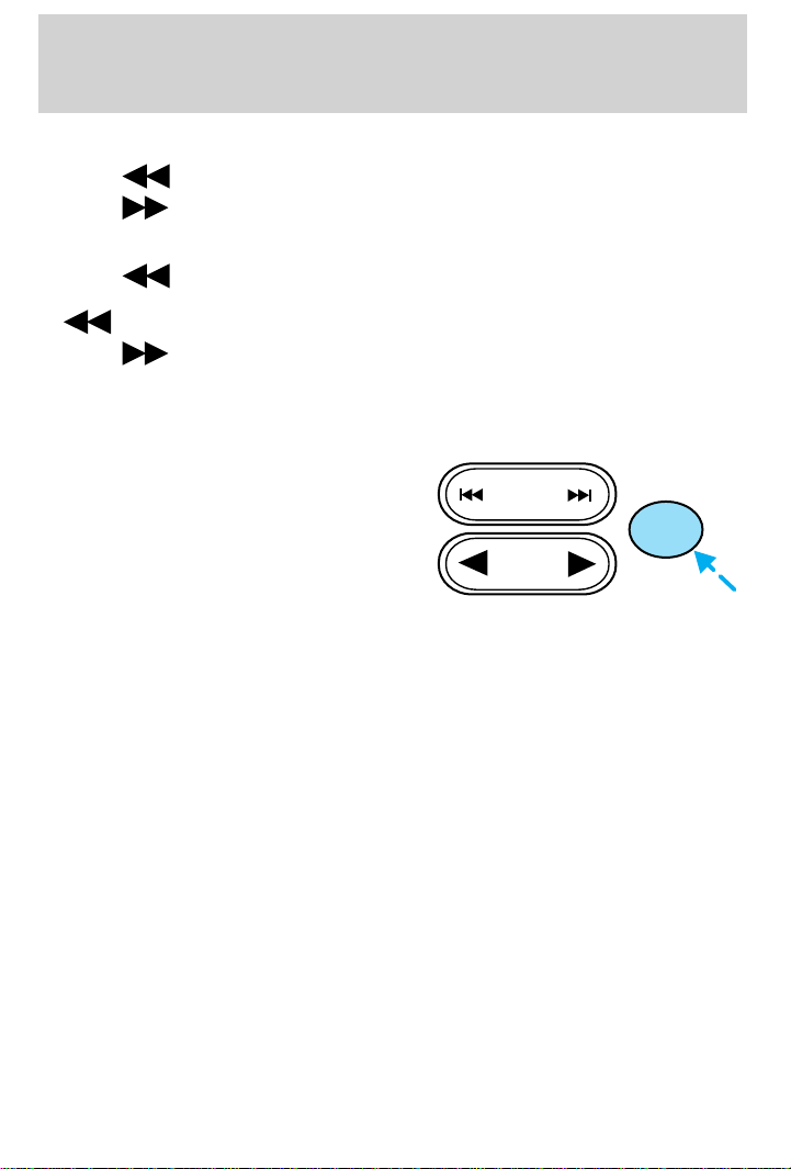
• Press to listen to the previous selection on the tape.
• Press
Seek function in CD mode (if equipped)
• Press to seek to the previous track of the current disc. If a
selection has been playing for three seconds or more and you press
• Press
the last track has been completed, the first track of the current disc
will automatically replay.
Scan function
The scan function works in radio,
tape or CD mode (if equipped).
Scan function in radio mode
Press the SCAN control to hear a brief sampling of all listenable stations
on the frequency band. Press the control again to stop the scan mode.
Scan function in tape mode
Press the SCAN control to hear a short sampling of all selections on the
tape. (The tape scans in a forward direction. At the end of the tape’s
first side, direction automatically reverses to the opposite side of the
tape.) To stop on a particular selection, press the control again.
Scan function in CD mode (if equipped)
Press the SCAN control to hear a short sampling of all selections on the
CD. (The CD scans in a forward direction, wrapping back to the first
track at the end of the CD.) To stop on a particular selection, press the
control again.
Radio station memory preset
The radio is equipped with six station memory preset controls. These
controls can be used to select up to six preset AM stations and twelve
FM stations (six in FM1 and six in FM2).
to listen to the next selection on the tape.
, the CD changer will replay that selection from the beginning.
to seek forward to the next track of the current disc. After
SEEK
TRACK
SCAN
TUNE
DISCS
29
Page 30
Controls and features
Setting memory preset stations
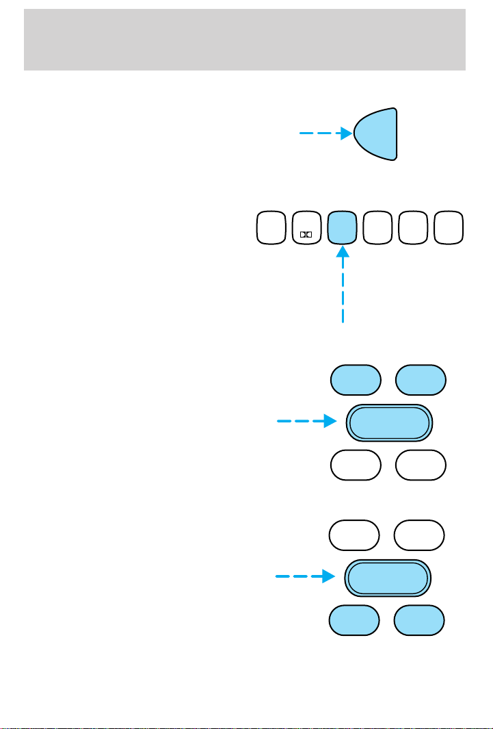
1. Select the frequency band with
the AM/FM select control.
2. Select a station. Refer to Tune adjust or Seek function for more
information on selecting a station.
3. Press and hold a memory preset
control until the sound returns,
1
SIDE 1-2
23456
indicating the station is held in
memory on the control you selected.
Bass/treble adjust
• The bass adjust control allows
you to increase or decrease the
audio system’s bass output.
• The treble adjust control allows
you to increase or decrease the
audio system’s treble output.
AM
FM
COMP
BASS TREB
–+
BAL
FADE
SHUF
Speaker balance/fade adjust
• Speaker sound distribution can be
adjusted between the right and
left speakers.
• Speaker sound can be adjusted
between the front and rear
speakers.
30
BASS TREB
–+
BAL
FADE
Page 31
Controls and features
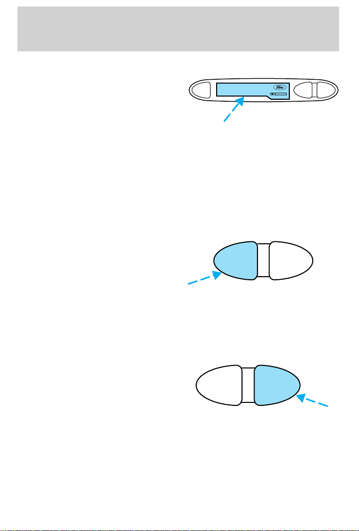
Inserting a tape
Push only slightly when inserting a
cassette tape (with the open edge
EJ
to the right). A cassette deck
loading mechanism pulls the tape in
the rest of the way.
You can switch from CD (if equipped) to tape play by inserting a tape
into the cassette deck.
Tape play select
Insert a tape to begin tape play.
Push only slightly when inserting a cassette tape (with the open edge to
the right). A cassette deck loading mechanism pulls the tape in the rest
of the way.
Rewind
The rewind control works in tape
and CD modes (if equipped).
REW
• In tape mode, radio play will
continue until rewind is stopped
(with the TAPE control) or the
beginning of the tape is reached.
• In CD mode, pressing the REW control for less than three seconds
results in slow rewind. Pressing the control for more than three
seconds results in fast rewind.
Fast forward
The fast forward control works in
tape and CD modes (if equipped).
• In the tape mode, tape direction
REW
FF
will automatically reverse when
the end of the tape is reached.
• In CD mode, pressing the control for less than three seconds results in
slow forward action. Pressing the control for more than three seconds
results in fast forward action.
DOLBY B NR
FF
REW
FF
31
Page 32
Controls and features
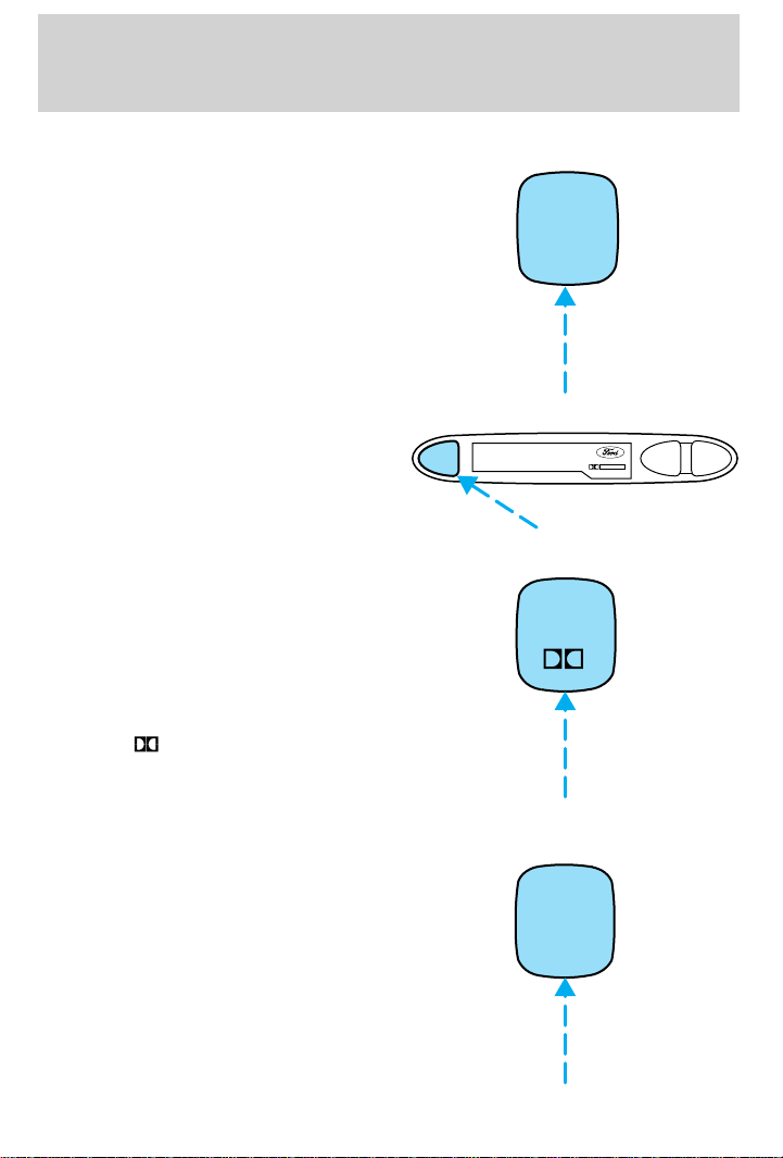
Tape side select
Press this control to play the
alternate side of a tape.
Eject function
Press the control to stop and eject a
tape.
DolbyTnoise reduction
Dolbyt noise reduction
manufactured under license from
Dolby Laboratories Licensing
Corporation operates only in tape
mode. Dolbyt reduces the amount
of hiss and static during tape
playback.
Press the
deactivate) Dolbyt noise reduction.
button to activate (and
1
SIDE 1-2
EJ
DOLBY B NR
REW
FF
2
Compression adjust
Compression adjust works in CD
mode (if equipped), and brings soft
and loud CD passages together for a
more consistent listening level.
Press the COMP control to activate
and deactivate compression adjust.
32
5
COMP
Page 33
Shuffle feature
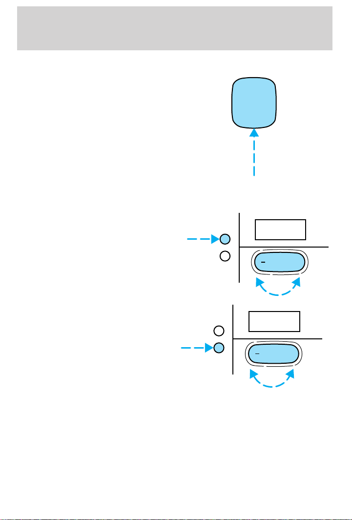
The shuffle feature operates in CD
mode (if equipped) and plays all
tracks on the current disc in random
order. If equipped with the CD
changer, the shuffle feature
continues to the next disc after all
tracks are played.
Press the SHUFFLE control to start
this feature. Random order play will
continue until the SHUFFLE control
is pressed again.
Setting the clock
To set the hour, press the hour (h)
control and press:
• (+) to increase the hour and
• (−) to decrease the hour
To set the minute, press the minute
(m) control and press:
• (+) to increase the minute and
• (−) to decrease the minute
Controls and features
6
SHUF
H
M
H
M
12:
+
:01
+
33
Page 34
Controls and features
CD changer (if equipped)
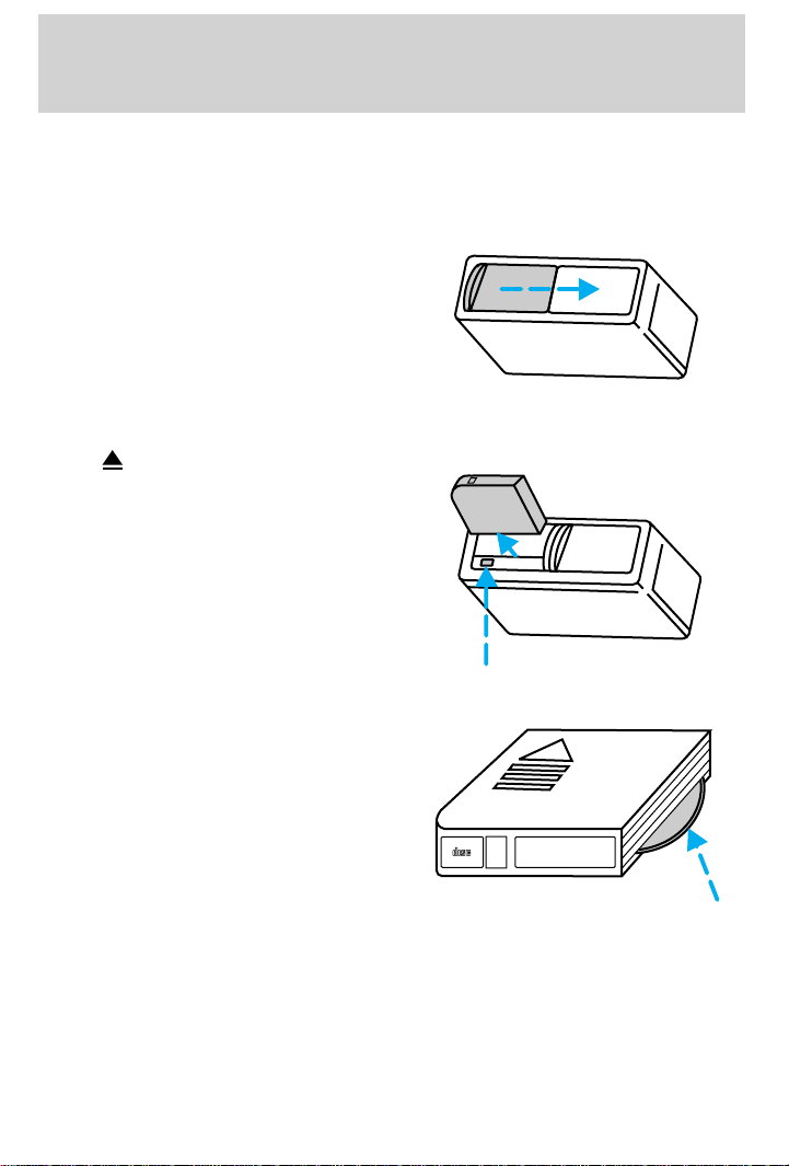
The CD changer is located in the trunk of your vehicle.
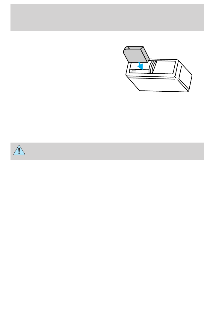
Slide the door to access the CD
changer magazine.
Press
to eject the magazine.
Make sure only one disc is inserted
in each slot. Each disc must be
inserted with the label surface
upward. You may insert up to six
CDs.
DIGITAL AUDIO
COMPACT
6
5
4
6 COMPACT DISC MAGAZINE
3
2
1
34
Page 35
Controls and features
The magazine does not need to be
full for the changer to operate.
Radio power must be turned on to play the CDs in the changer. The
magazine may be stored in the glove box when not being used.
The CD magazine may be inserted or ejected with the radio power off.
Troubleshooting the CD changer (if equipped)
The laser beam used in the compact disc player is harmful to the
eyes. Do not attempt to disassemble the case.
If sound skips:
• You may be traveling on a rough road, playing badly scratched discs or
the disc may be dirty. Skipping will not scratch the discs or damage
the player.
If your changer does not work, it may be that:
• A disc is already loaded where you want to insert a disc.
• The disc is inserted with the label surface downward.
• The disc is dusty or defective.
• The player’s internal temperature is above 60°C (140°F). Allow the
player to cool down before operating.
• A disc with format and dimensions not within industry standards is
inserted.
Cleaning compact discs
Inspect all discs for contamination before playing. If necessary, clean
discs only with an approved CD cleaner and wipe from the center out to
the edge. Do not use circular motion.
35
Page 36

Controls and features
CD and CD changer care
• Handle discs by their edges only. Never touch the playing surface.
• Do not expose discs to direct sunlight or heat sources for extended
periods of time.
• Do not insert more than one disc into each slot of the CD changer
magazine.
Cleaning cassette player (if equipped)
Clean the tape player head with a cassette cleaning cartridge after ten to
twelve hours of play in order to maintain the best sound and operation.
Cassette and cassette player care
• Use only cassettes that are 90 minutes long or less.
• Do not expose tapes to direct sunlight, high humidity, extreme heat or
extreme cold. Allow tapes that may have been exposed to extreme
temperatures to reach a moderate temperature before playing.
• Tighten very loose tapes by inserting a finger or pencil into the hole
and turning the hub.
• Remove loose labels before inserting tapes.
• Do not leave tapes in the cassette player for a long time when not
being played.
Radio frequency information
The Federal Communications Commission (FCC) and the Canadian Radio
and Telecommunications Commission(CRTC) establish the frequencies AM
and FM stations may use for their broadcasts. Allowable frequencies are:
AM 530, 540–1600, 1610 kHz
FM 87.9, 88.1–107.1, 107.9 MHz
Not all frequencies are used in a given area.
Radio reception factors
Three factors can affect radio reception:
• Distance/strength. The further an FM signal travels, the weaker it is.
The listenable range of the average FM station is approximately 40 km
(24 miles). This range can be affected by “signal modulation”. Signal
modulation is a process radio stations use to increase their
strength/volume relative to other stations.
36
Page 37
Controls and features
• Terrain. Hills, mountains and tall buildings between your vehicle’s
antenna and the radio station signal can cause FM reception problems.
Static can be caused on AM stations by power lines, electric fences,
traffic lights and thunderstorms. Moving away from an interfering
structure (out of its “shadow”) returns your reception to normal.
• Station overload. Weak signals are sometimes captured by stronger
signals when you pass a broadcast tower. A stronger signal may
temporarily overtake a weaker signal and play while the weak station
frequency is displayed.
The audio system automatically switches to single channel reception if it
will improve the reception of a station normally received in stereo.
Audio system warranties and service
Refer to the “Warranty Guide” for audio system warranty information.
If service is necessary, see your dealer or a qualified technician.
CLIMATE CONTROL SYSTEM
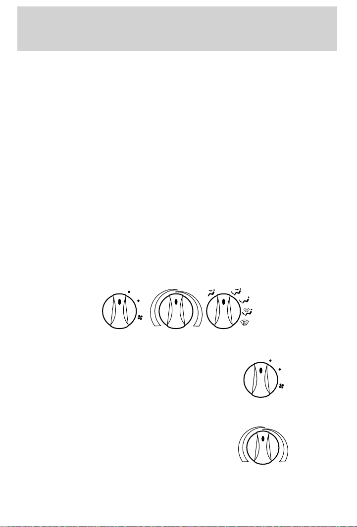
Heater only system (if equipped)
LO
HI
Fan speed control
Controls the volume of air circulated
in the vehicle.
Temperature control knob
Controls the temperature of the
airflow inside the vehicle. On
heater-only systems, the air cannot
be cooled below the outside
temperature.
OFF
LO
HI
37
Page 38
Controls and features
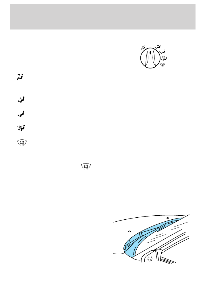
Mode selector control
Controls the direction of the airflow
to the inside of the vehicle.
• (Panel)-Distributes outside air through the instrument panel
registers.
• OFF-Outside air is shut out and the fan will not operate.
(Panel and floor)-Distributes outside air through the instrument
•
panel registers and the floor ducts.
• (Floor)-Allows for maximum heating. Distributes outside air
through the floor ducts.
• (Floor and defrost)-Distributes outside air through the floor ducts
and the windshield defroster ducts.
• -Distributes outside air through the windshield defroster ducts. It
can be used to clear ice or fog from the windshield.
Operating tips
• In humid weather, select before driving. This will help to reduce
your windshield from fogging. After a few minutes, select any desired
position.
• To prevent humidity buildup inside the vehicle, don’t drive with the
climate control system in the OFF position.
• Don’t put objects under the front seat that will interfere with the
airflow to the back seats.
• Remove any snow, ice or leaves
from the air intake area (at the
bottom of the windshield under
the hood).
OFF
• When placing objects on top of your instrument panel, be careful to
not place them over the defroster outlets. These objects can block
38
Page 39
Controls and features
airflow and reduce your ability to see through your windshield. Also,
avoid placing small objects on top of your instrument panel. These
objects can fall down into the defroster outlets and block airflow and
possibly damage your climate control system.
Do not place objects on top of the instrument panel, as these
objects may become projectiles in a collision or sudden stop.
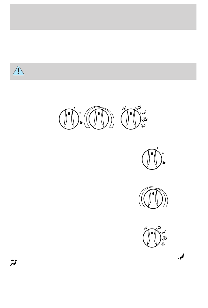
Manual heating and air conditioning system (if equipped)
LO
HI
MAX
A/C
OFF
A/C
Fan speed control
Controls the volume of air circulated
LO
in the vehicle.
HI
Temperature control knob
Controls the temperature of the
airflow inside the vehicle.
Mode selector control
Controls the direction of the airflow
to the inside of the vehicle.
OFF
A/C
MAX
A/C
The air conditioning compressor will operate in all modes except
. However, the air conditioning will only function if the outside
temperature is about 10°C (50°F) or higher.
Since the air conditioner removes considerable moisture from the air
during operation, it is normal if clear water drips on the ground under
and
39
Page 40
Controls and features
the air conditioner drain while the system is working and even after you
have stopped the vehicle.
Under normal conditions, your vehicle’s climate control system should be
left in any position other than MAX A/C or OFF when the vehicle is
parked. This allows the vehicle to “breathe” through the outside air inlet
duct. In snowy or dirty condition, leave the mode selector in the OFF
position.
• MAX A/C-Uses recirculated air to cool the vehicle. MAX A/C is noisier
than A/C but more economical and will cool the inside of the vehicle
faster. Airflow will be from the instrument panel registers. This mode
can also be used to prevent undesirable odors from entering the
vehicle.
• A/C-Uses outside air to cool the vehicle. It is quieter than MAX A/C
but not as economical. Airflow will be from the instrument panel
registers.
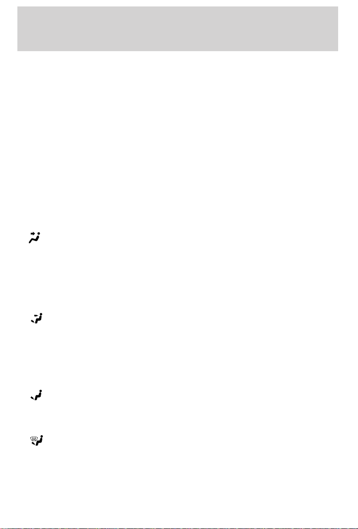
(Panel)-Distributes outside air through the instrument panel
•
registers. However, the air will not be cooled below the outside
temperature because the air conditioning does not operate in this
mode.
• OFF-Outside air is shut out and the fan will not operate. For short
periods of time only, use this mode to prevent undesirable odors from
entering the vehicle.
•
•
•
(Panel and floor)-Distributes outside air through the instrument
panel registers and the floor ducts. Heating and air conditioning
capabilities are provided in this mode. For added customer comfort,
when the temperature control knob is anywhere in between the full
hot and full cold positions, the air distributed through the floor ducts
will be slightly warmer than the air sent to the instrument panel
registers.
(Floor)-Allows for maximum heating by distributing outside air
through the floor ducts. However, the air will not be cooled below the
outside temperature because the air conditioning does not operate in
this mode.
(Floor and defrost)-Distributes outside air through the windshield
defroster ducts and the floor ducts. Heating and air conditioning
capabilities are provided in this mode. For added customer comfort,
when the temperature control knob is anywhere in between the full
hot and full cold positions, the air distributed through the floor ducts
will be slightly warmer than the air sent to the
40
Page 41
Controls and features
instrument panel registers. If the temperature is about 10°C (50°F) or
higher, the air conditioner will automatically dehumidify the air to
reduce fogging.
•
Operating tips
• In humid weather, select before driving. This will reduce your
• To prevent humidity buildup inside the vehicle, don’t drive with the
• Don’t put objects under the front seat that will interfere with the
• Remove any snow, ice or leaves
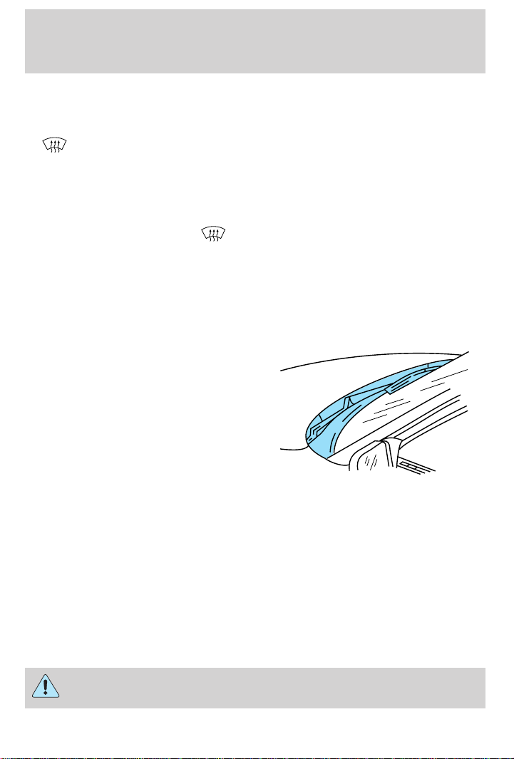
-Distributes outside air through the windshield defroster ducts. It
can be used to clear ice or fog from the windshield. If the temperature
is about 10°C (50°F) or higher, the air conditioner will automatically
dehumidify the air to reduce fogging.
windshield from fogging. After a few minutes, select any desired
position.
climate control system in the OFF position.
airflow to the back seats.
from the air intake area (at the
bottom of the windshield under
the hood).
• If your vehicle has been parked with the windows closed during hot
weather, the air conditioner will do a much faster job of cooling if you
drive for two or three minutes with the windows open. This will force
most of the hot, stale air out of the vehicle. Then operate your air
conditioner as you would normally.
• When placing objects on top of your instrument panel, be careful to
not place them over the defroster outlets. These objects can block
airflow and reduce your ability to see through your windshield. Also,
avoid placing small objects on top of your instrument panel. These
objects can fall down into the defroster outlets and block airflow and
possibly damage your climate control system.
Do not place objects on top of the instrument panel, as these
objects may become projectiles in a collision or sudden stop.
41
Page 42
Controls and features
REAR WINDOW DEFROSTER
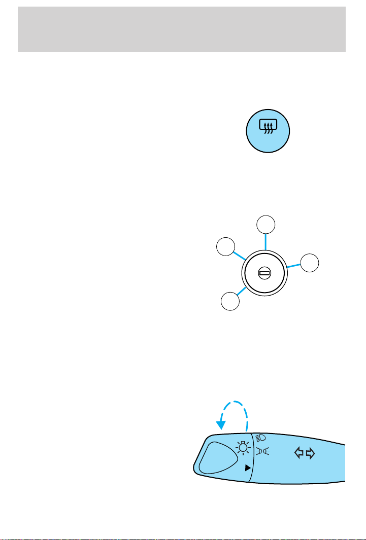
Clears the rear window of thin ice and fog. To operate:
1. Turn the ignition to the ON position.
2. Press and release the control
once to turn on. The light will be lit
while the rear window defroster is
on.
3. Press and release the control
again to turn off.
The defroster will automatically turn off after fifteen minutes.
POSITIONS OF THE IGNITION
1. LOCK, locks the steering wheel,
gearshift lever (automatic transaxle
only) and allows key removal. On
vehicles with a manual transaxle
2
push the key in while turning to
lock.
2. ACCESSORY, allows the electrical
accessories such as the radio to
operate while the engine is not
running.
3. ON, all electrical circuits operational. Warning lights illuminated. Key
position when driving.
4. START, cranks the engine. Release the key as soon as the engine
starts.
R.DEF
3
N
O
S
I
I
C
T
C
A
I
I
A
I
I
K
0
C
O
L
4
R
T
1
HEADLAMP CONTROL
Rotate the headlamp control to the
first position to turn on the parking
lamps. Rotate to the second position
to also turn on the headlamps.
42
OFF
Page 43
Controls and features
Daytime running lamps (DRL) (if equipped)
Turns the headlamps on with a reduced output. To activate:
• the ignition must be in the ON position and
• the headlamp control is in the OFF or Parking lamps position.
Always remember to turn on your headlamps at dusk or during
inclement weather. The Daytime Running Light (DRL) System
does not activate your tail lamps and generally may not provide
adequate lighting during these conditions. Failure to activate your
headlamps under these conditions may result in a collision.
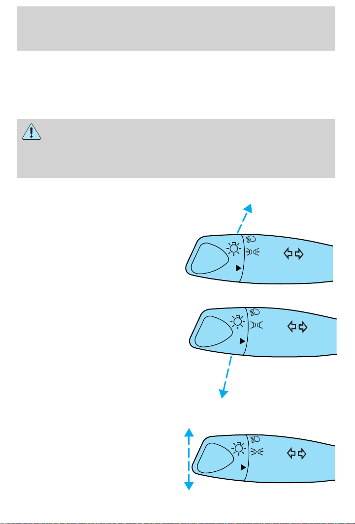
High beams
Push forward to activate.
OFF
Flash to pass
Pull toward you to activate and
release to deactivate.
TURN SIGNAL CONTROL
• Push down to activate the left
turn signal.
• Push up to activate the right turn
signal.
OFF
OFF
43
Page 44
Controls and features
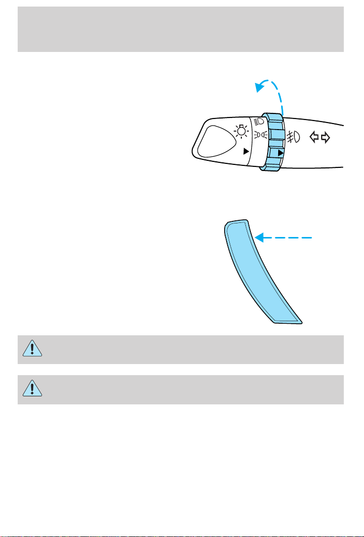
FOGLAMP CONTROL (IF EQUIPPED)
Rotate forward to activate.
SPEED CONTROL (IF EQUIPPED)
To turn speed control on
• Press ON.
Vehicle speed cannot be controlled
until the vehicle is traveling at or
above 48 km/h (30 mph).
OFF OFF
ON
OFF
44
Do not use the speed control in heavy traffic or on roads that
are winding, slippery, or unpaved.
Do not shift the gearshift lever into N (Neutral) with the speed
control on.
Page 45
Controls and features
To turn speed control off
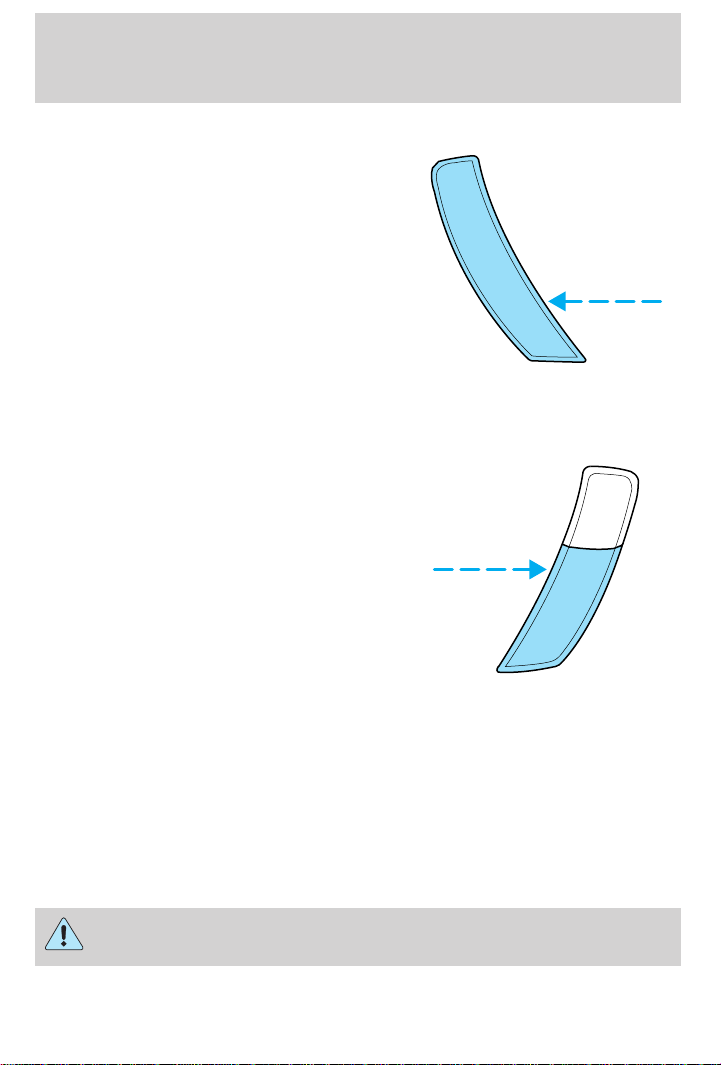
• Press OFF or
• Turn off the vehicle ignition.
Once speed control is switched off, the previously programmed set speed
will be erased.
To set a speed
• Press SET/SET ACC/SET ACCEL.
For speed control to operate, the
speed control must be ON and
the vehicle speed must be greater
than 48 km/h (30 mph).
ON
OFF
RSM
SET
ACC
CST
If you drive up or down a steep hill, your vehicle speed may vary
momentarily slower or faster than the set speed. This is normal.
Speed control cannot reduce the vehicle speed if it increases above the
set speed on a downhill. If your vehicle speed is faster than the set
speed while driving on a downhill, you may want to shift to the next
lower gear or apply the brakes to reduce your vehicle speed.
If your vehicle slows down more than 16 km/h (10 mph) below your set
speed on an uphill, your speed control will disengage. This is normal.
Pressing RES/RSM/RESUME will re-engage it.
Do not use the speed control in heavy traffic or on roads that
are winding, slippery, or unpaved.
45
Page 46
Controls and features
To set a higher set speed
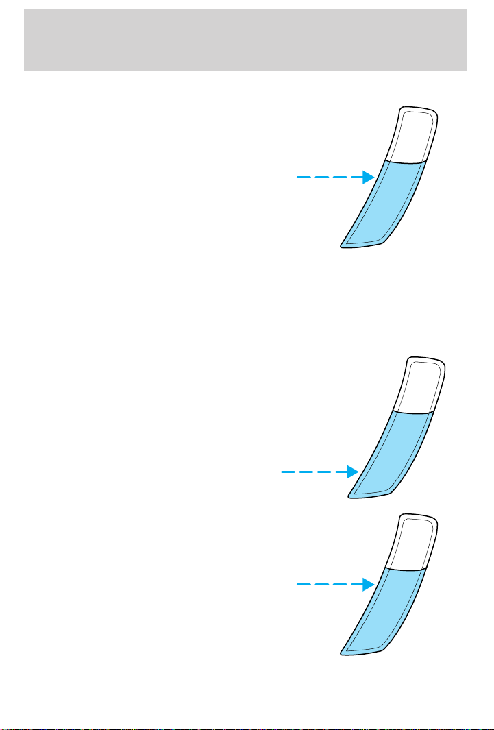
• Press and hold SET/SET
ACC/SET ACCEL. Release the
control when the desired vehicle
speed is reached or
• Press and release SET/SET
ACC/SET ACCEL. Each press will
increase the set speed by
1.6 km/h (1 mph) or
• Accelerate with your accelerator
pedal. When the desired vehicle
speed is reached, press and release SET/SET ACC/SET ACCEL.
You can accelerate with the accelerator pedal at any time during speed
control usage. Releasing the accelerator pedal will return your vehicle to
the previously programmed set speed.
To set a lower set speed
• Press and hold CST/COAST.
Release the control when the
desired speed is reached or
• Press and release CST/COAST.
Each press will decrease the set
speed by 1.6 km/h (1 mph) or
RSM
SET
ACC
CST
RSM
SET
ACC
• Depress the brake pedal. When
the desired vehicle speed is
reached, press SET/SET ACC/
SET ACCEL.
46
CST
RSM
SET
ACC
CST
Page 47
To disengage speed control
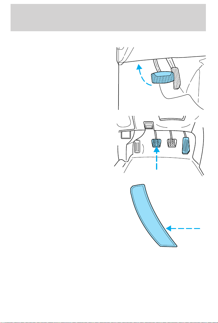
• Depress the brake pedal or
• Depress the clutch pedal (if
equipped)
Disengaging the speed control will
not erase the previously
programmed set speed.
Pressing OFF will erase the
previously programmed set speed.
Controls and features
ON
OFF
47
Page 48
Controls and features
To return to a previously set speed
• Press RES/RSM/RESUME. For
RES/RSM/RESUME to operate,
the vehicle speed must be faster
than 48 km/h (30 mph).
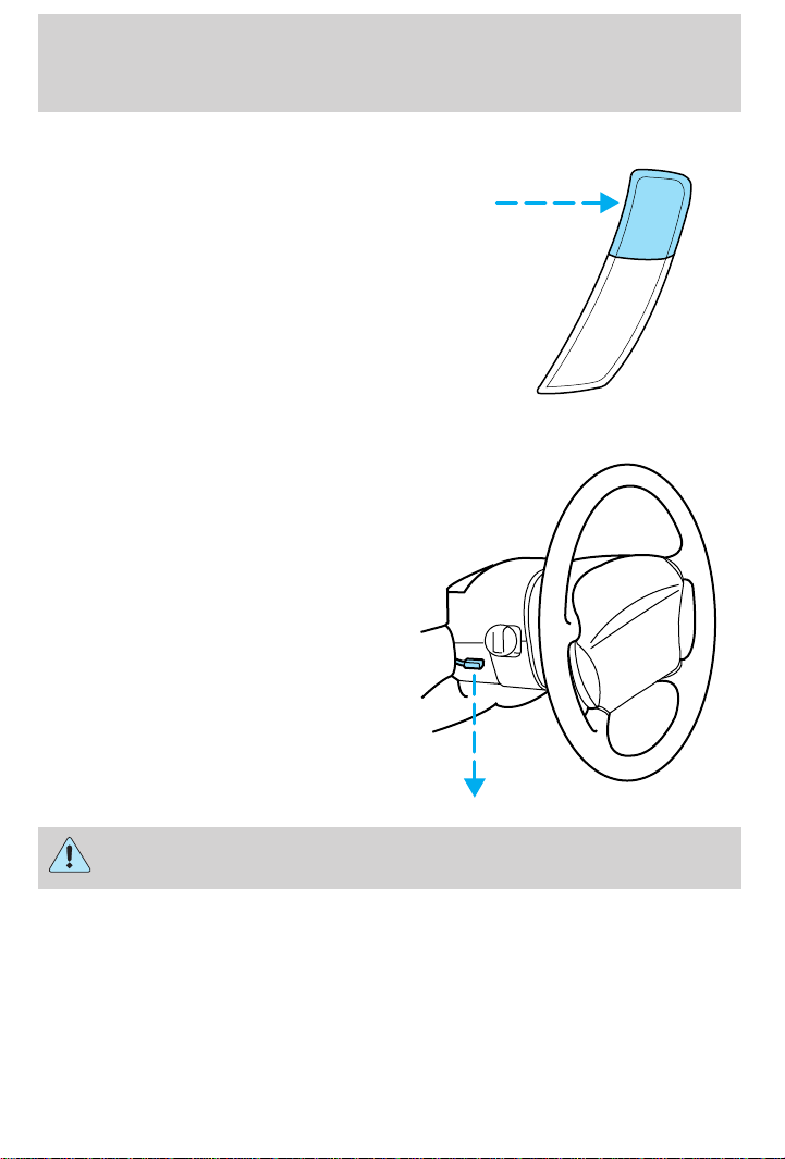
TILT STEERING (IF EQUIPPED)
Pull the tilt steering control down to
move the steering wheel up or
down. Hold the control while
adjusting the wheel to the desired
position, then push the control back
up to lock the steering wheel in
position.
RSM
SET
ACC
CST
Never adjust the steering wheel when the vehicle is moving.
HAZARD FLASHER
For information on the hazard flasher control, refer to Hazard flasher in
the Roadside emergencies chapter.
48
Page 49
WINDSHIELD WIPER AND WASHER
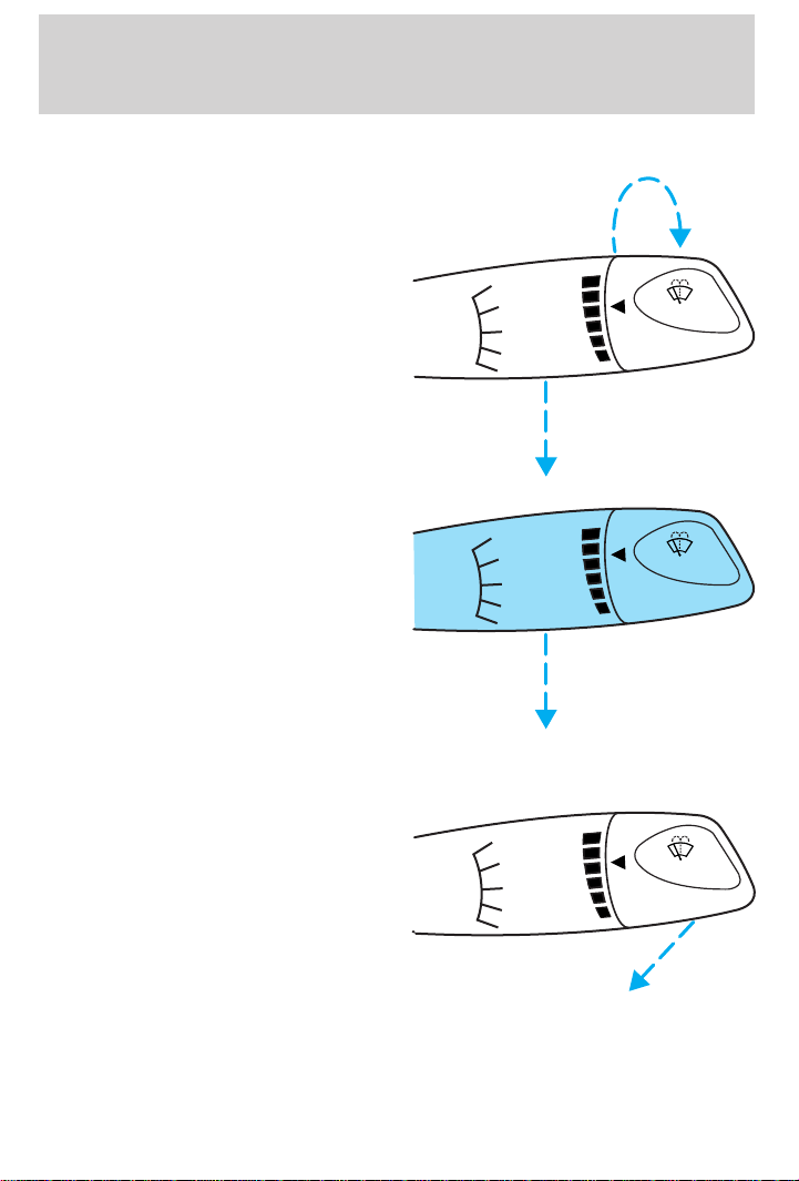
• For intermittent wiping, move the
control down one position and
rotate the wiper switch to the
desired position.
Controls and features
MIST
OFF
INT
1
2
F
INT
PULL
S
• For low speed wiping, move the
control down two positions.
• For high speed wiping, move the
control down three positions.
MIST
OFF
INT
1
2
• For mist wiping, move the control up one position.
• To spray the washer fluid, pull
the wiper control toward you.
MIST
OFF
INT
1
2
F
INT
PULL
S
F
INT
PULL
S
49
Page 50
Controls and features
Rear window wiper/washer controls (if equipped)
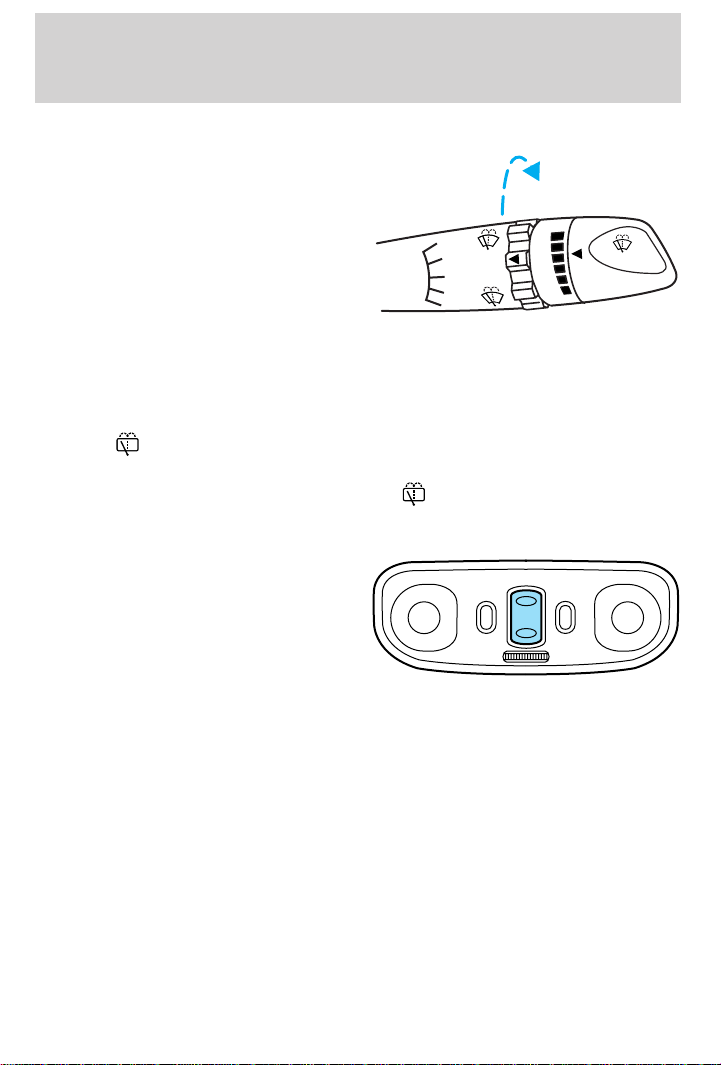
For rear wiper operation, rotate the
rear wiper and washer control to the
desired position.
• To turn rear wipers on, rotate the
rear wiper/washer control upward
to the ON position.
• To turn rear wipers off, rotate the
MIST
OFF
INT
1
2
ON
OFF
rear wiper/washer control
downward to the OFF position.
For rear washer fluid operation, rotate the rear wiper/washer control to
the desired position.
• To turn rear washers on, rotate the rear wiper/washer control upward
to the
position for your desired length of washer time.
• To turn rear washers on briefly (for quick cleaning), rotate the
wiper/washer control downward to the position and release.
MOON ROOF (IF EQUIPPED)
• Press and hold OPEN to raise the
moon roof to the vent position.
• Press OPEN again to fully open
the moon roof.
• Press the opposite end of the
toggle control to close the moon
roof from either position.
F
INT
PULL
S
OPEN
Sliding shade
The moon roof has a sliding shade that you can open or close when the
moon roof is closed.
50
Page 51
Controls and features
INTERIOR LAMPS
Dome lamp and map lamps (if equipped)
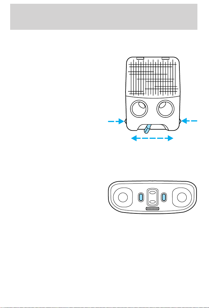
The dome lamp is located overhead
between the driver and passenger
seats.
The dome lamp will stay on if the
control is moved to the ON position.
When the control is moved to the
DOOR position, the lamp will only
come on if a door is opened. If the
control is moved to the OFF
position, the lamp will not come on
at all.
The map lamps and controls are
located on the dome lamp. Press the
controls on either side of each map
lamp to activate the lamps.
Map lamps (if equipped)
The map lamps and controls are located on the dome lamp. Press the
controls on either side of the dome lamp to activate the map lamps.
If equipped with a moon roof, the
map lamps are located on the moon
roof control panel. Press the control
next to the map lamp to illuminate
the lamp.
OFF DOOR ON
OPEN
51
Page 52
Controls and features
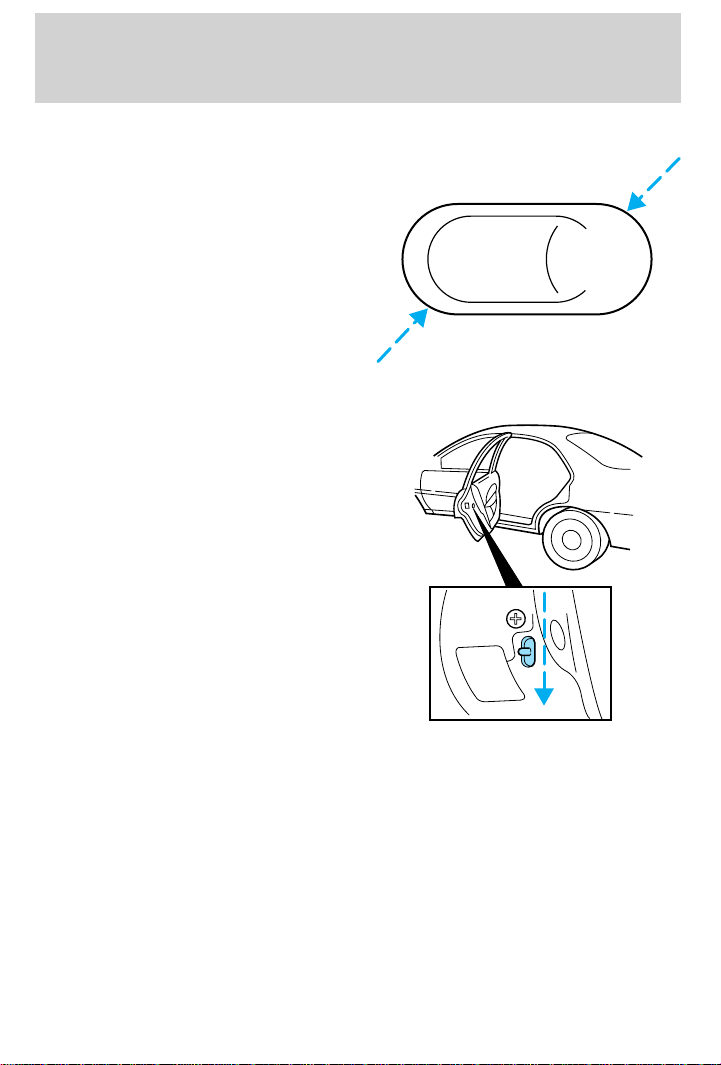
POWER DOOR LOCKS (IF EQUIPPED)
Press U to unlock all doors and L to
lock all doors.
CHILDPROOF DOOR LOCKS
When these locks are set, the rear
doors cannot be opened from the
inside. The rear doors can be
opened from the outside when the
doors are unlocked.
The childproof locks are located on
rear edge of each rear door and
must be set separately for each
door. Setting the lock for one door
will not automatically set the lock
for both doors.
Move lock control down to engage
the lock. Move control up to
disengage childproof locks.
U L
52
Page 53
Controls and features
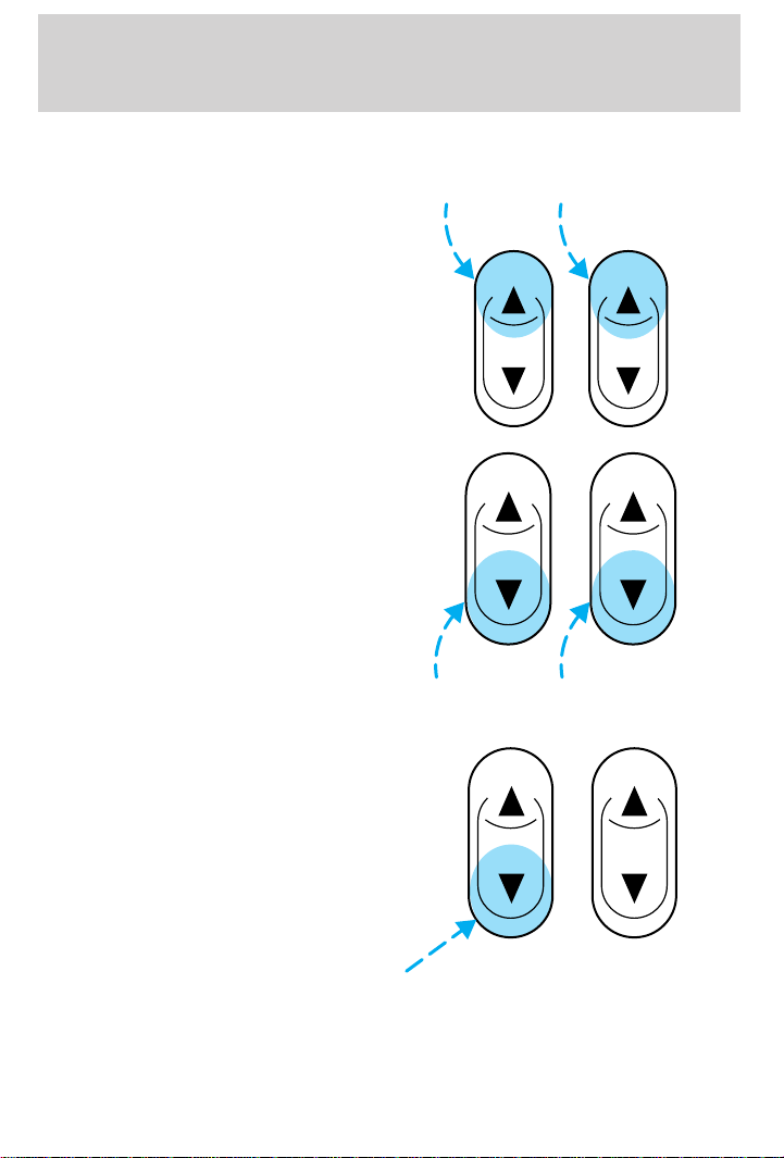
POWER WINDOWS (IF EQUIPPED)
Press and hold the rocker switches to open and close windows.
• Press the top portion of the
rocker switch to close.
• Press the bottom portion of the
rocker switch to open.
Express down
To make the driver window open
fully without holding the window
control, press the driver window
control completely down and release
quickly. Depress again to stop
window operation.
53
Page 54
Controls and features
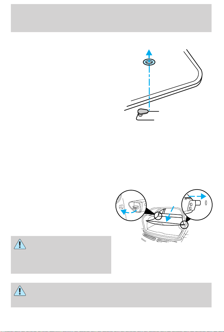
POSITIVE RETENTION FLOOR MAT
Position the floor mat so that the
eyelet is over the pointed end of the
retention post and rotate forward to
lock in. Make sure that the mat does
not interfere with the operation of
the accelerator or the brake pedal.
To remove the floor mat, reverse the
installation procedure.
FUEL PUMP SHUT-OFF SWITCH
Refer to the Roadside emergencies chapter for instructions on how to
operate the fuel pump shut-off switch.
CARGO COVER (IF EQUIPPED)
Your vehicle may be equipped with a cargo area shade that covers the
luggage compartment of your vehicle.
To install the shade:
1. Fasten the cover into the
mounting brackets (make sure the
cover is right side up).
2. Pull the end of the shade toward
you and hook the sides into the
notches in the rear trim panels.
To prevent the possibility of
injuries, the fasteners for
the cargo area cover must be
properly attached to the mounting
clips on the rear trim panels.
Do not place any objects on the cargo area cover. They may
obstruct your vision or strike occupants of the vehicle in the
case of a sudden stop or collision.
54
Page 55
Controls and features
REMOTE ENTRY SYSTEM
Your vehicle may have an all-door remote entry system or a driver’s door
only remote entry system.
The all-door remote entry system allows you to:
• lock or unlock all vehicle doors without a key.
• arm and disarm the anti-theft system. (For more information on the
anti-theft system, refer to Anti-theft system in this chapter.)
• open the trunk or unlock liftgate (wagons).
• activate the panic alarm.
The driver’s door only entry system allows you to:
• lock the driver’s door and liftgate (wagons).
• unlock the driver’s door only without a key.
• activate the panic alarm.
• open the trunk or unlock liftgate (wagons).
The remote entry features only operate with the ignition in the OFF
position.
If there is any potential remote keyless entry problem with your vehicle,
ensure ALL key fobs (remote entry transmitters) are brought to the
dealership, to aid in troubleshooting.
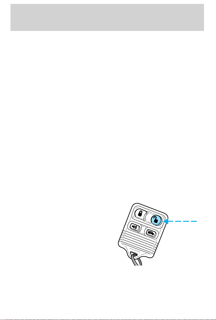
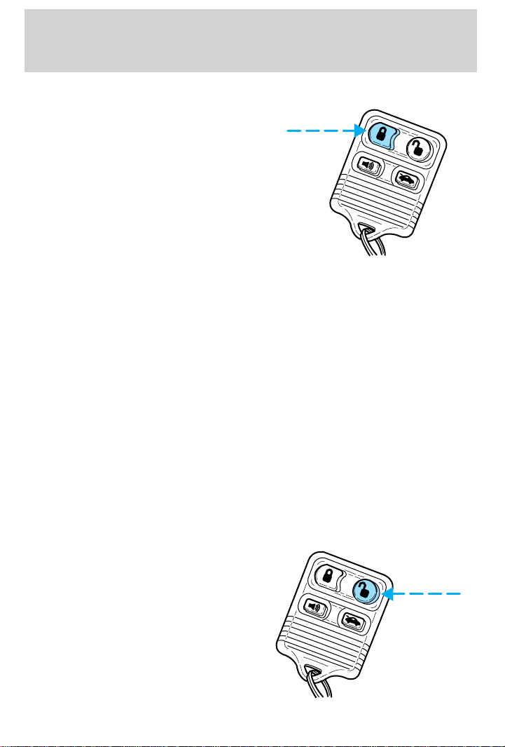
Unlocking the doors
Press this control to unlock the
driver’s door. The interior lamps will
illuminate.
With the all-door remote entry
system, press the control a second
time within five seconds to unlock
all doors and liftgate.
55
Page 56
Controls and features
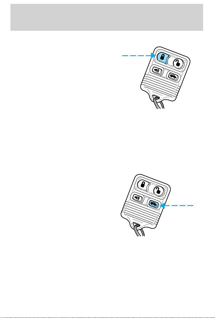
Locking the doors
Press this control to lock all doors
(and liftgate on wagons). On
vehicles equipped with the driver’s
door only remote entry system, only
the driver’s (and liftgate on wagons)
door will lock.
To confirm doors are closed and
locked, press the lock control a
second time within five seconds.
The door(s) will lock again, the
horn will chirp once and the lamps
will flash.
If any of the doors are open or ajar, the horn will make two quick chirps,
reminding you to properly close the doors.
This process will also arm your anti-theft system (if equipped). For more
information on arming the anti-theft system, refer to Anti-theft system in
this chapter.
Opening the trunk
Press the control once to open the
trunk. On wagons, pressing the
control will unlock (but not open)
the liftgate.
Ensure that the trunk is closed and
latched before driving your vehicle.
Failure to latch the trunk
completely may cause objects to fall
out of the trunk or block the rear
view.
56
Page 57
Controls and features
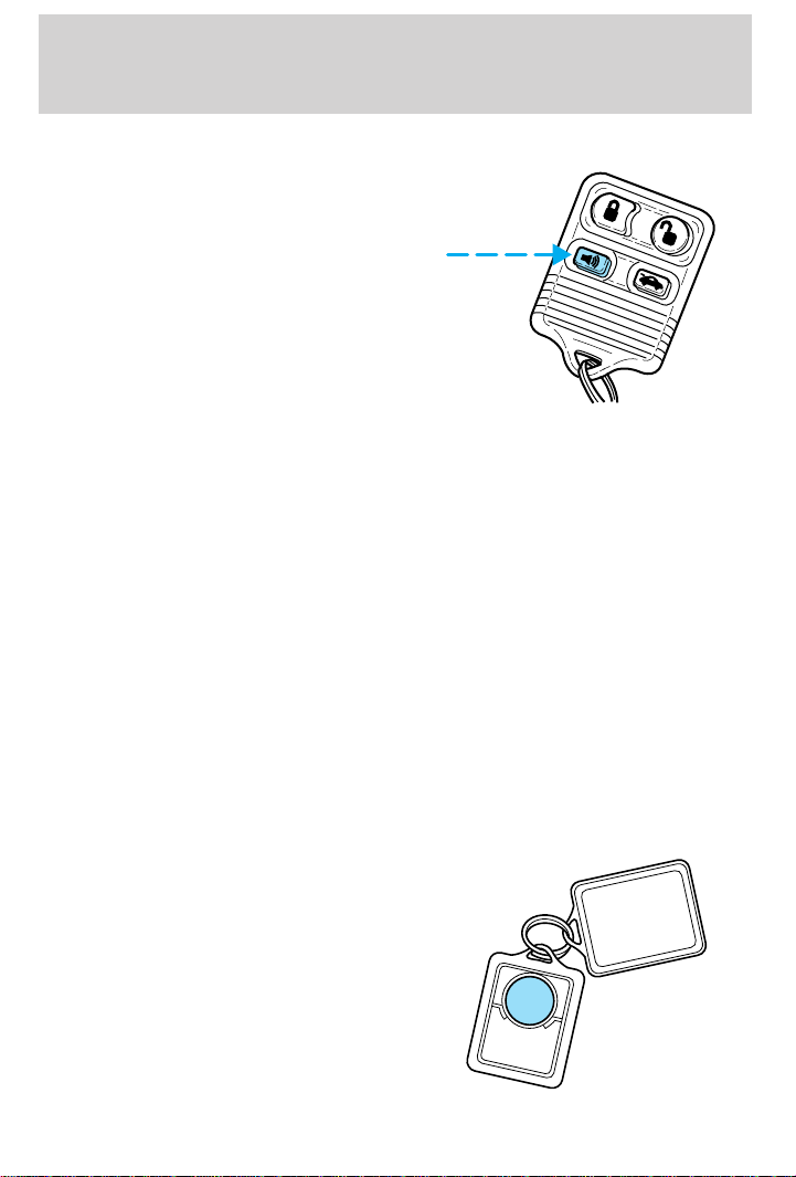
Sounding a panic alarm
Press this control to activate the
alarm.
To deactivate the alarm, press the
control again or turn the ignition to
ACC or ON.
This device complies with part 15 of
the FCC rules and with RS-210 of
Industry Canada. Operation is subject
to the following two conditions: (1)
This device may not cause harmful
interference, and (2) This device must accept any interference received,
including interference that may cause undesired operation.
Changes or modifications not expressly approved by the party
responsible for compliance could void the user’s authority to
operate the equipment.
Replacing the battery
The remote transmitter is powered by one coin type three-volt lithium
battery CR2032 or equivalent. Typical operating range will allow you to
be up to 10 meters (33 feet) away from your vehicle. A decrease in
operating range can be caused by:
• weather conditions
• nearby radio towers
• structures around the vehicle
• other vehicles parked next to the vehicle
To replace the battery:
1. Twist a thin coin between the two
halves of the transmitter near the
key ring. DO NOT TAKE THE
FRONT PART OF THE
TRANSMITTER APART.
2. Place the positive (+) side of new
battery in the same orientation.
Refer to the diagram inside the
transmitter unit.
Snap the two halves back together.
3.
57
Page 58
Controls and features
Replacement of the battery will not cause the remote transmitter to
become deprogrammed from your vehicle. The remote transmitter should
operate normally after battery replacement.
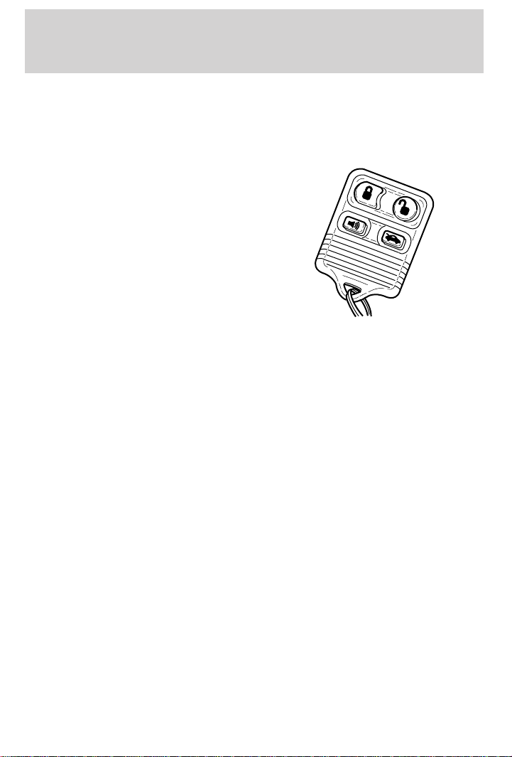
Replacing lost transmitters
Take all your vehicle’s transmitters
to your dealer if service is required.
If you purchase additional
transmitters (up to four may be
programmed), perform the following
procedure:
To reprogram the transmitters, place
the key in the ignition and turn
from OFF to ON eight times in rapid
succession (within 10 seconds)
ending in ON. After doors lock/unlock, press any control on all
transmitters (up to four). With each control press of the transmitters,
the door should cycle (lock/unlock) to confirm programming. When
completed, turn the ignition to OFF. The door locks should cycle
(lock/unlock) one last time and the horn will chirp to confirm completion
of programming.
All transmitters must be programmed at the same time.
Illuminated entry
Interior lamps will illuminate when UNLOCK or PANIC control is
pressed. The lamps will illuminate for approximately 20 seconds or until
the key is inserted in the ignition and turned to ON or until LOCK
control is pressed. The dome lamp must be set to the DOOR position in
order for the illuminated entry system to operate.
ANTI-THEFT SYSTEM (IF EQUIPPED)
When armed, the anti-theft system will help prevent your vehicle from
unauthorized entry.
If there is any potential perimeter anti-theft problem with your vehicle,
ensure ALL key fobs (remote entry transmitters) are brought to the
dealership, to aid in troubleshooting.
58
Page 59
Controls and features
Arming the anti-theft system
Turn the ignition to OFF and press
the lock control on the remote entry
transmitter.
Identifying an armed system
While the system is arming, the THEFT light in the instrument cluster
will illuminate for 30 seconds. After 30 seconds, THEFT will flash,
indicating the system is armed.
If the system is arming with the doors open, the THEFT light will stay
illuminated until all the doors are closed and then illuminate for 30
seconds and begin flashing.
When an unauthorized entry occurs, the activated system will:
• flash the parking lamps and the THEFT light
• sound the horn
The flashing parking lamps and the honking horn automatically shut off
after about three minutes and will remain off unless another
unauthorized entry is attempted.
Disarming the anti-theft system
Disarming an untriggered anti-theft system
Press the unlock control to disarm a
triggered or untriggered system.
59
Page 60
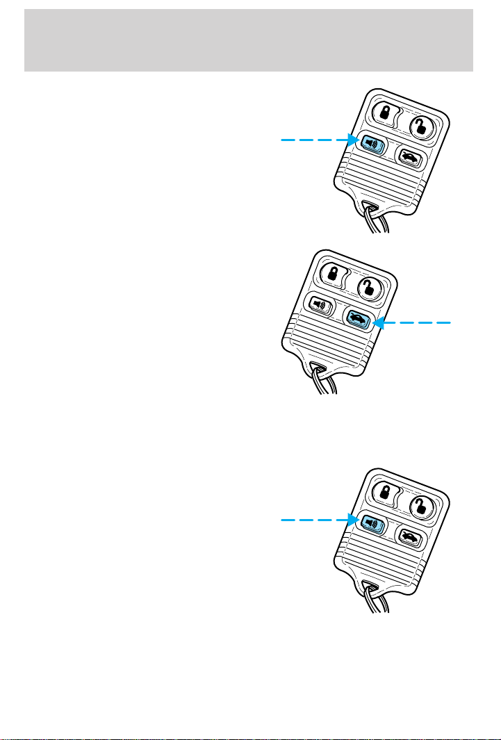
Controls and features
A triggered system may also be
disarmed by inserting the key and
turning the ignition to ON/ACC or
by pressing the panic control.
On station wagons models, pressing
the trunk control only will unlock
and disarm the anti-theft system.
On non-station wagon models,
pressing the trunk control will
prevent the alarm from sounding
until the trunk is closed again.
Using the ignition key to unlock doors/trunk/liftgate will not disarm the
anti-theft system.
Disarming a triggered anti-theft system
Press either the unlock or panic
control to disarm the system.
A triggered system may also be
disarmed by inserting the key and
turning the ignition to ACC or ON.
60
Page 61
Seating and safety restraints
SEATING
Adjustable head restraints
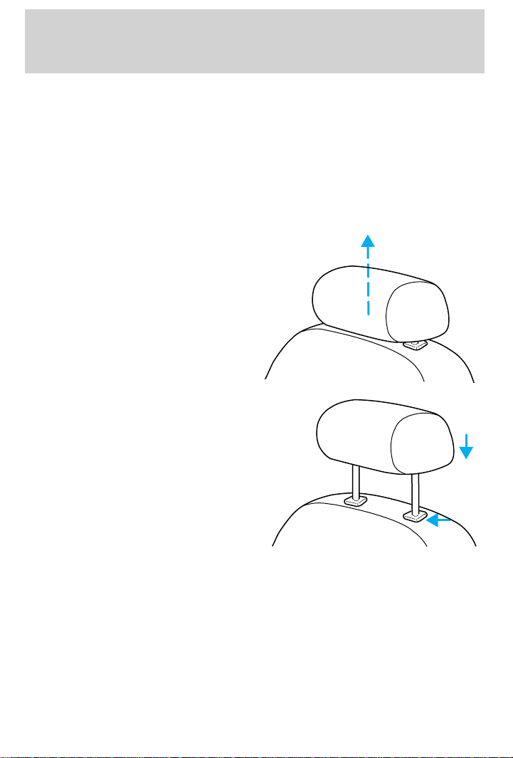
Your vehicle’s seats may be equipped with head restraints which are
vertically adjustable. The purpose of these head restraints is to help limit
head motion in the event of a rear collision. To properly adjust your head
restraints, lift the head restraint so that it is located directly behind your
head or as close to that position as possible. Refer to the following to
raise and lower the head restraints.
The head restraints can be moved
up and down.
Push control to lower head restraint.
61
Page 62

Seating and safety restraints
Adjusting the front manual seat
Never adjust the driver’s seat or seatback when the vehicle is
moving.
Do not pile cargo higher than the seatbacks to avoid injuring
people in a collision or sudden stop.
Always drive and ride with your seatback upright and the lap
belt snug and low across the hips.
Lift handle to move seat forward or
backward.
Pull lever up to adjust seatback.
62
Page 63
Seating and safety restraints
Driver seat memory recliner (if equipped)
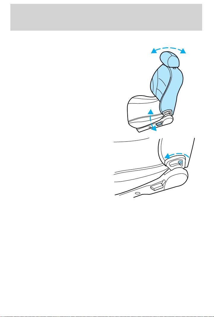
• Pull control to adjust seatback.
• To retain selected seatback
position, release seatback by
moving memory recliner control
forward to release seatback.
• Push seatback rearward until the seatback latches. This will be the
first position selected.
63
Page 64
Seating and safety restraints
Folding rear seats (if equipped)
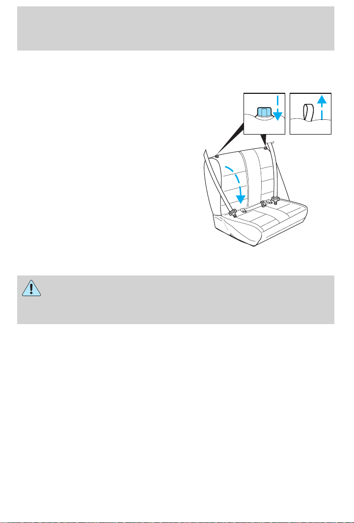
Folding down the rear seats
To fold the seatback down:
• Press the latch control downward
or pull up on strap and
• Pull the seatback forward and
down.
Returning the seat to the upright position
Check to see that the seat and seatback is latched securely in
position. Keep floor area free of objects that would prevent
proper seat engagement. Never attempt to adjust the seat while the
vehicle is in motion.
To return the seat to the upright/normal seating position:
• Rotate seat upward and latch.
The full rear bench seat is shown. The split-folding rear seat (if
equipped) operates in a similar manner.
64
Page 65
Seating and safety restraints
SAFETY RESTRAINTS
Safety restraints precautions
Always drive and ride with your seatback upright and the lap
belt snug and low across the hips.
To reduce the risk of injury, make sure children sit where they
can be properly restrained.
Never let a passenger hold a child on his or her lap while the
vehicle is moving. The passenger cannot protect the child from
injury in a collision.
All occupants of the vehicle, including the driver, should always
properly wear their safety belts, even when an air bag SRS is
provided.
It is extremely dangerous to ride in a cargo area, inside or
outside of a vehicle. In a collision, people riding in these areas
are more likely to be seriously injured or killed. Do not allow people to
ride in any area of your vehicle that is not equipped with seats and
safety belts. Be sure everyone in your vehicle is in a seat and using a
safety belt properly.
Each seating position in your vehicle has a specific safety belt
assembly which is made up of one buckle and one tongue that
are designed to be used as a pair. 1) Use the shoulder belt on the
outside shoulder only. Never wear the shoulder belt under the arm.
2) Never swing the safety belt around your neck over the inside
shoulder. 3) Never use a single belt for more than one person.
Always transport children 12 years old and under in the back
seat and always properly use appropriate child restraints.
65
Page 66
Seating and safety restraints
Combination lap and shoulder belts
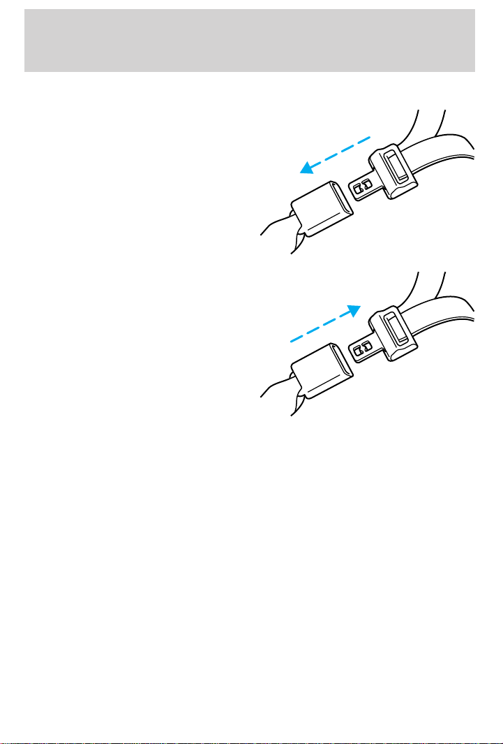
1. Insert the belt tongue into the
proper buckle (the buckle closest to
the direction the tongue is coming
from) until you hear a snap and feel
it latch. Make sure the tongue is
securely fastened in the buckle.
2. To unfasten, push the release
button and remove the tongue from
the buckle.
The front and rear outboard safety restraints in the vehicle are
combination lap and shoulder belts. The front passenger and rear seat
outboard safety belts have two types of locking modes described below:
Automatic locking mode
In this mode, the shoulder belt is automatically pre-locked. The belt will
still retract to remove any slack in the shoulder belt.
The automatic locking mode is not available on the driver safety belt.
When to use the automatic locking mode
• When a tight lap/shoulder fit is desired.
• Anytime a child safety seat is installed in a passenger front or
outboard rear seating position (if equipped). Refer to Safety
Restraints for Children or Safety Seats for Children later in this
chapter.
66
Page 67
Seating and safety restraints
How to use the automatic locking mode
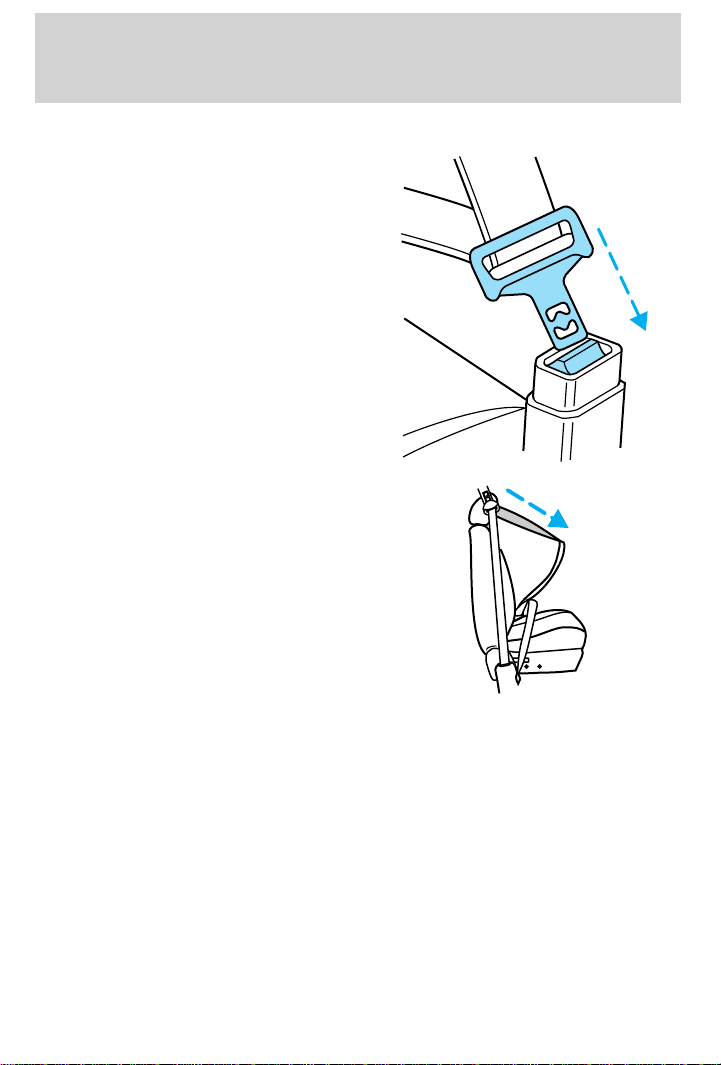
• Buckle the combination lap and
shoulder belt.
• Grasp the shoulder portion and
pull downward until the entire
belt is extracted.
• Allow the belt to retract. As the belt retracts, you will hear a clicking
sound. This indicates the safety belt is now in the automatic locking
mode.
How to disengage the automatic locking mode
Disconnect the combination lap/shoulder belt and allow it to retract
completely to disengage the automatic locking mode and activate the
vehicle sensitive (emergency) locking mode.
67
Page 68
Seating and safety restraints
Front safety belt height adjustment (if equipped)
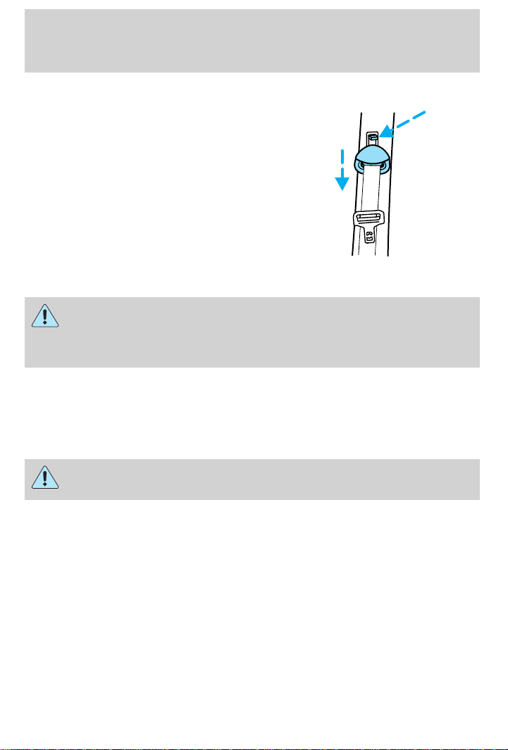
Your vehicle has safety belt height
adjustments for the driver and front
passenger. Adjust the height of the
shoulder belt so the belt rests
across the middle of your shoulder.
To lower the shoulder belt height,
push the button and slide the height
control down. To raise the height of
the shoulder belt, slide the height
adjuster up. Pull down on the height
adjustment assembly to make sure it
is locked in place.
Position the shoulder belt height adjuster so that the belt rests
across the middle of your shoulder. Failure to adjust the safety
belt properly could reduce the effectiveness of the safety belt and
increase the risk of injury in a collision.
Lap belts (if equipped)
Adjusting the lap belt
The lap belt does not adjust automatically.
68
The lap belts should fit snugly and as low as possible around the
hips, not around the waist.
Page 69
Seating and safety restraints
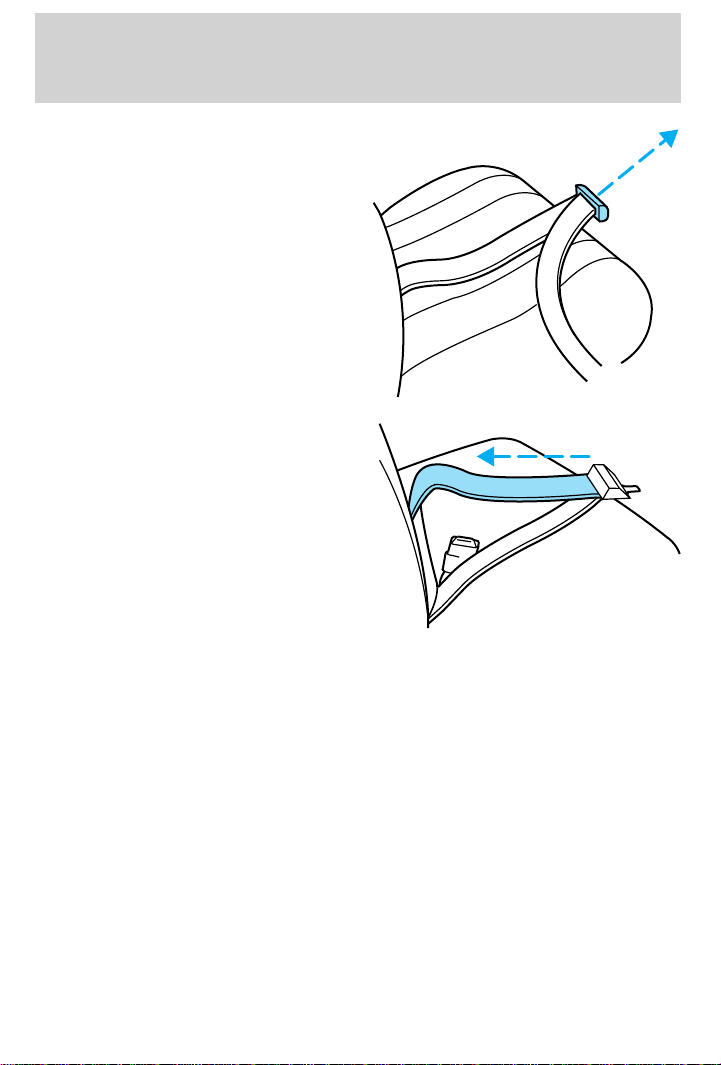
Insert the tongue into the correct
buckle (the buckle closest to the
direction the tongue is coming
from). To lengthen the belt, turn the
tongue at a right angle to the belt
and pull across your lap until it
reaches the buckle. To tighten the
belt, pull the loose end of the belt
through the tongue until it fits
snugly across the hips.
Shorten and fasten the belt when
not in use.
Safety belt extension assembly
If the safety belt assembly is too short, even when fully extended, 20 cm
(8 inches) can be added to the safety belt assembly by adding a safety
belt extension assembly (part number 611C22). Safety belt extension
assemblies can be obtained from your dealer at no cost.
Use only extensions manufactured by the same supplier as the safety
belt. Manufacturer identification is located at the end of the webbing on
the label. Also, use the safety belt extension only if the safety belt is too
short for you when fully extended. Do not use extensions to change the
fit of the shoulder belt across the torso.
Safety belt warning light and indicator chime
The seat belt warning light illuminates in the instrument cluster and a
chime sounds to remind the occupants to fasten their safety belts.
69
Page 70
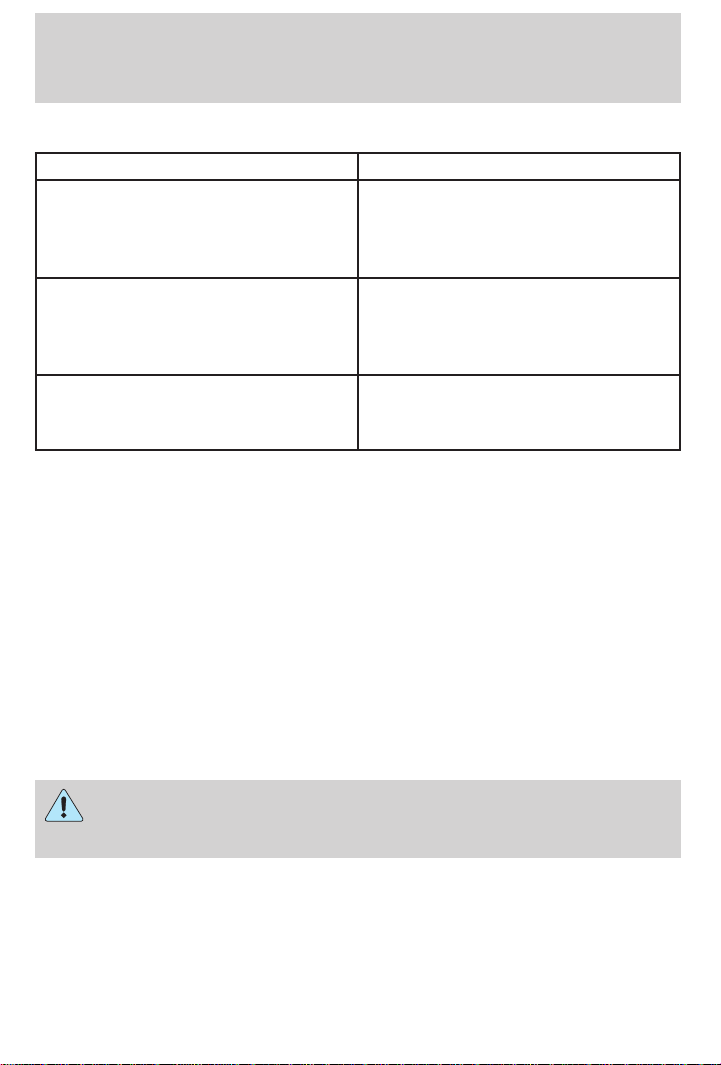
Seating and safety restraints
Conditions of operation
If... Then...
The driver’s safety belt is not
buckled before the ignition switch
is turned to the ON position...
The driver’s safety belt is buckled
while the indicator light is
illuminated and the warning chime
is sounding...
The driver’s safety belt is buckled
before the ignition switch is turned
to the ON position...
Safety belt maintenance
Inspect the safety belt systems periodically to make sure they work
properly and are not damaged. Inspect the safety belts to make sure
there are no nicks, wears or cuts, replacing if necessary. All safety belt
assemblies, including retractors, buckles, front seat belt buckle
assemblies, buckle support assemblies (slide bar-if equipped), shoulder
belt height adjusters (if equipped), child safety seat tether bracket
assemblies (if equipped), and attaching hardware, should be inspected
after a collision. Ford recommends that all safety belt assemblies used in
vehicles involved in a collision be replaced. However, if the collision was
minor and a qualified technician finds that the belts do not show damage
and continue to operate properly, they do not need to be replaced.
Safety belt assemblies not in use during a collision should also be
inspected and replaced if either damage or improper operation is noted.
The safety belt warning light
illuminates for one to two minutes
and the warning chime sounds for
four to eight seconds.
The safety belt warning light and
warning chime turn off.
The safety belt warning light and
indicator chime remain off.
Failure to inspect and if necessary replace the safety belt
assembly under the above conditions could result in severe
personal injuries in the event of a collision.
Refer to Cleaning and maintaining the safety belts in the
Maintenance and care section.
70
Page 71
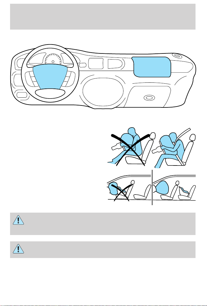
Seating and safety restraints
AIR BAG SUPPLEMENTAL RESTRAINT SYSTEM (SRS)
Important supplemental restraint system (SRS) precautions
The supplemental restraint system
is designed to work with the safety
belt to help protect the driver and
right front passenger from certain
upper body injuries.
Air bags DO NOT inflate slowly or
gently and the risk of injury from a
deploying air bag is greatest close to
the trim covering the air bag
module.
All occupants of the vehicle, including the driver, should always
properly wear their safety belts, even when an air bag SRS is
provided.
Always transport children 12 years old and under in the back
seat and always properly use appropriate child restraints.
71
Page 72
Seating and safety restraints
National Highway Traffic Safety Administration (NHTSA)
recommends a minimum distance of at least 25 cm
(ten [10] inches) between an occupant’s chest and the driver air bag
module.
Never place your arm over the air bag module as a deploying air
bag can result in serious arm fractures or other injuries.
Steps you can take to properly position yourself away from the airbag:
• Move your seat to the rear as far as you can while still reaching the
pedals comfortably.
• Recline the seat slightly (one or two degrees) from the upright
position.
Do not put anything on or over the air bag module. Placing
objects on or over the air bag inflation area may cause those
objects to be propelled by the air bag into your face and torso causing
serious injury.
Do not attempt to service, repair, or modify the Air Bag
Supplemental Restraint System or its fuses. See your Ford or
Lincoln-Mercury dealer.
72
Page 73
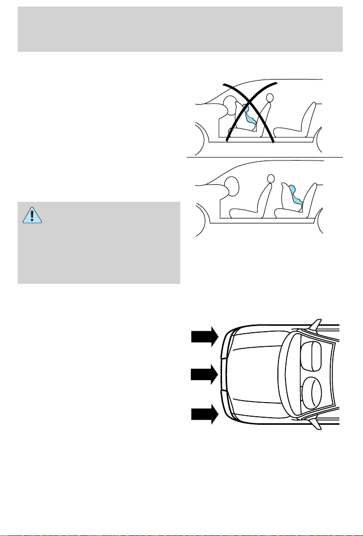
Seating and safety restraints
Children and air bags
For additional important safety
information, read all information on
safety restraints in this guide.
Children must always be properly
restrained. Accident statistics
suggest that children are safer when
properly restrained in the rear
seating positions than in the front
seating position. Failure to follow
these instructions may increase the
risk of injury in a collision.
Air bags can kill or injure a
child in a child seat.
NEVER place a rear-facing child
seat in front of an active air bag. If
you must use a forward-facing
child seat in the front seat, move
the seat all the way back.
How does the air bag supplemental restraint system work?
The air bag SRS is designed to
activate when the vehicle sustains
longitudinal deceleration sufficient
to cause the sensors to close an
electrical circuit that initiates air
bag inflation.
The fact that the air bags did not
inflate in a collision does not mean
that something is wrong with the
system. Rather, it means the forces
were not of the type sufficient to
cause activation. Air bags are designed to inflate in frontal and
near-frontal collisions, not rollover, side-impact, or rear-impacts unless
the collision causes sufficient longitudinal deceleration.
73
Page 74
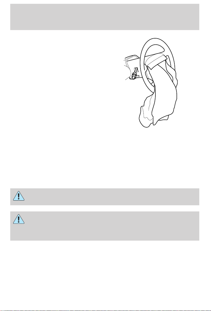
Seating and safety restraints
The air bags inflate and deflate
rapidly upon activation. After air bag
deployment, it is normal to notice a
smoke-like, powdery residue or
smell the burnt propellant. This may
consist of cornstarch, talcum
powder (to lubricate the bag) or
sodium compounds (e.g., baking
soda) that result from the
combustion process that inflates the
air bag. Small amounts of sodium
hydroxide may be present which
may irritate the skin and eyes, but
none of the residue is toxic.
While the system is designed to help
reduce serious injuries, contact with
a deploying air bag may also cause abrasions, swelling or temporary
hearing loss. Because air bags must inflate rapidly and with considerable
force, there is the risk of death or serious injuries such as fractures,
facial and eye injuries or internal injuries, particularly to occupants who
are not properly restrained or are otherwise out of position at the time
of air bag deployment. Thus, it is extremely important that occupants be
properly restrained as far away from the air bag module as possible while
maintaining vehicle control.
Several air bag system components get hot after inflation. Do not
touch them after inflation.
If the air bag is deployed, the air bag will not function again
and must be replaced immediately. If the air bag is not
replaced, the unrepaired area will increase the risk of injury in a
collision.
The SRS consists of:
• driver and passenger air bag modules (which include the inflators and
air bags),
• one or more impact and safing sensors,
• a readiness light and tone,
• and the electrical wiring which connects the components.
74
Page 75

Seating and safety restraints
The diagnostic module monitors its own internal circuits and the
supplemental air bag electrical system warning (including the impact
sensors), the system wiring, the air bag system readiness light, the air
bag back up power and the air bag ignitors.
Determining if the system is operational
The SRS uses a readiness light in the instrument cluster or a tone to
indicate the condition of the system. Refer to the Air bag readiness
section in the Instrumentation chapter. Routine maintenance of the air
bag is not required.
A difficulty with the system is indicated by one or more of the following:
• The readiness light will either
flash or stay lit.
• The readiness light will not
illuminate immediately after
ignition is turned on.
• A series of five beeps will be heard. The tone pattern will repeat
periodically until the problem and light are repaired.
If any of these things happen, even intermittently, have the SRS serviced
at your dealership or by a qualified technician immediately. Unless
serviced, the system may not function properly in the event of a
collision.
Disposal of air bags and air bag equipped vehicles
(including pretensioners)
For disposal of air bags or air bag equipped vehicles, see your local
dealership or qualified technician. Air bags MUST BE disposed of by
qualified personnel.
SAFETY RESTRAINTS FOR CHILDREN
See the following sections for directions on how to properly use safety
restraints for children. Also see Air Bag Supplemental Restraint System
(SRS) in this chapter for special instructions about using air bags.
Important child restraint precautions
You are required by law to use safety restraints for children in the U.S.
and Canada. If small children ride in your vehicle (generally children who
are four years old or younger and who weigh 18 kg [40 lbs] or less), you
must put them in safety seats made especially for children. Check your
75
Page 76

Seating and safety restraints
local and state or provincial laws for specific requirements regarding the
safety of children in your vehicle.
Never let a passenger hold a child on his or her lap while the
vehicle is moving. The passenger cannot protect the child from
injury in a collision.
Always follow the instructions and warnings that come with any infant or
child restraint you might use.
When possible, always place children under age 12 in the rear seat of your
vehicle. Accident statistics suggest that children are safer when properly
restrained in the rear seating positions than in the front seating position.
Children and safety belts
If the child is the proper size, restrain the child in a safety seat.
Children who are too large for child safety seats (as specified by your
child safety seat manufacturer) should always wear safety belts.
Follow all the important safety restraint and air bag precautions that
apply to adult passengers in your vehicle.
If the shoulder belt portion of a combination lap and shoulder belt can be
positioned so it does not cross or rest in front of the child’s face or neck, the
child should wear the lap and shoulder belt. Moving the child closer to the
center of the vehicle may help provide a good shoulder belt fit.
Do not leave children, unreliable adults, or pets unattended in
your vehicle.
To improve the fit of lap and shoulder belts on children who have
outgrown child safety seats, Ford recommends use of a belt-positioning
booster seat that is labelled as conforming to all Federal motor vehicle
safety standards. Belt-positioning booster seats raise the child and
provide a shorter, firmer seating cushion that encourages safer seating
posture and better fit of lap and shoulder belts on the child.
A belt-positioning booster should be used if the shoulder belt rests in
front of the child’s face or neck, or if the lap belt does not fit snugly on
both thighs, or if the thighs are too short to let the child sit all the way
back on the seat cushion when the lower legs hang over the edge of the
seat cushion. You may wish to discuss the special needs of your child
with your pediatrician.
76
Page 77
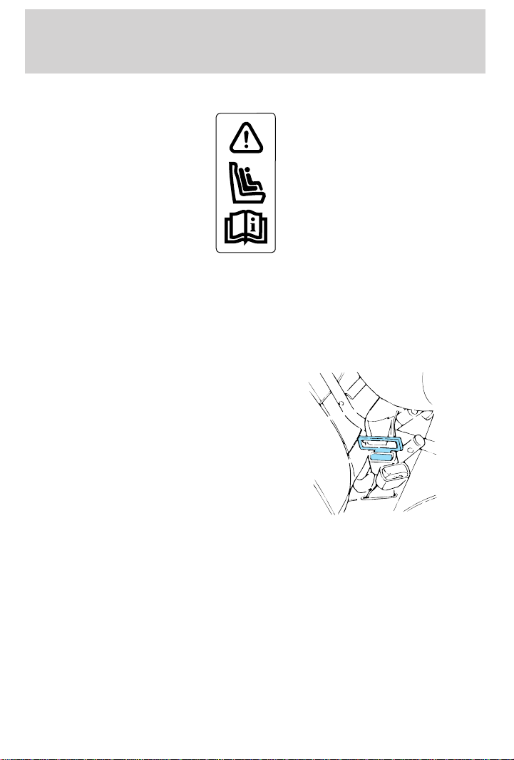
Seating and safety restraints
SAFETY SEATS FOR CHILDREN
Child and infant or child safety seats
Use a safety seat that is recommended for the size and weight of the child.
Carefully follow all of the manufacturer’s instructions with the safety seat
you put in your vehicle. If you do not install and use the safety seat properly,
the child may be injured in a sudden stop or collision.
When installing a child safety seat:
• Review and follow the information
presented in the Air Bag
Supplemental Restraint System
section in this chapter.
• Use the correct safety belt buckle
for that seating position.
• Insert the belt tongue into the
proper buckle until you hear a
snap and feel it latch. Make sure
the tongue is securely fastened in the buckle.
• Keep the buckle release button pointing up and away from the safety
seat, with the tongue between the child seat and the release button,
to prevent accidental unbuckling.
• Place seat back in upright position.
• Put the safety belt in the automatic locking mode. Refer to Automatic
locking mode (passenger side front and outboard rear seating
positions) (if equipped).
Ford recommends the use of a child safety seat having a top tether
strap. Install the child safety seat in a seating position which is capable
of providing a tether anchorage. For more information on top tether
straps, refer to Attaching safety seats with tether straps.
77
Page 78
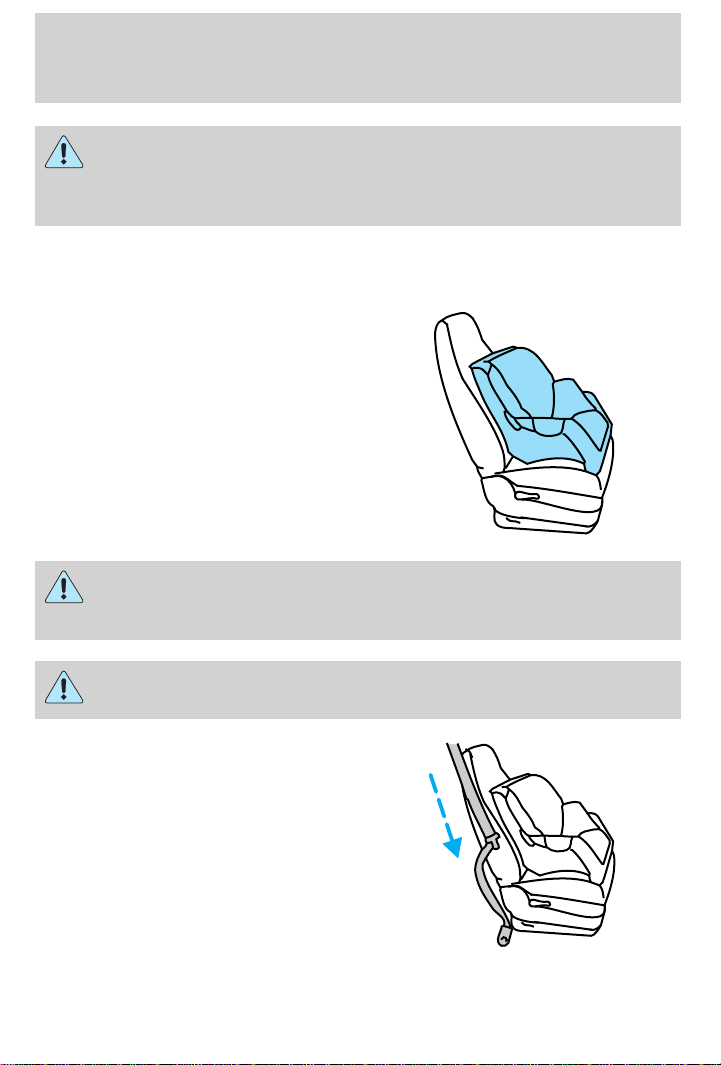
Seating and safety restraints
Carefully follow all of the manufacturer’s instructions included
with the safety seat you put in your vehicle. If you do not install
and use the safety seat properly, the child may be injured in a sudden
stop or collision.
Installing child safety seats in combination lap and shoulder belt
seating positions
1. Position the child safety seat in a
seat with a combination lap and
shoulder belt.
An air bag can kill or injure a child in a child seat. If you must
use a forward-facing child seat in the front seat, move seat all
the way back.
Children 12 and under should be properly restrained in the rear
seat whenever possible.
2. Pull down on the shoulder belt
and then grasp the shoulder belt
and lap belt together.
78
Page 79
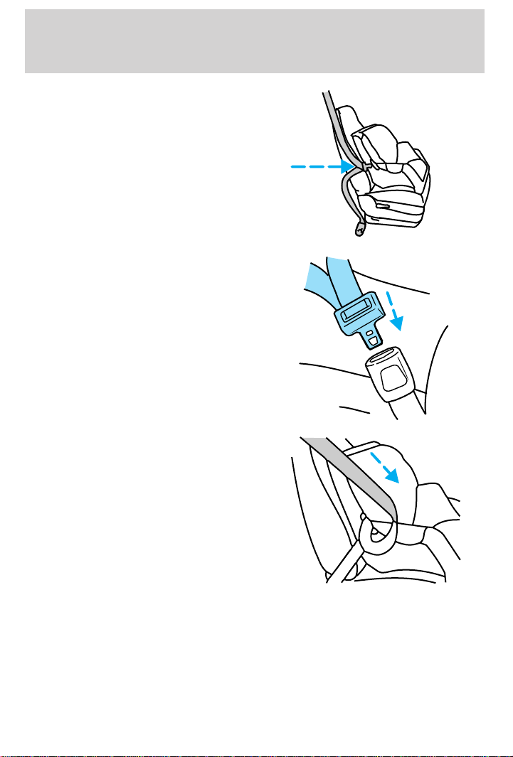
Seating and safety restraints
3. While holding the shoulder and
lap belt portions together, route the
tongue through the child seat
according to the child seat
manufacturer’s instructions. Be sure
the belt webbing is not twisted.
4. Insert the belt tongue into the
proper buckle (the buckle closest to
the direction the tongue is coming
from) for that seating position until
you hear a snap and feel the latch
engage. Make sure the tongue is
latched securely by pulling on it.
5. To put the retractor in the
automatic locking mode, grasp the
shoulder portion of the belt and pull
downward until all of the belt is
extracted and a click is heard.
6. Allow the belt to retract. The belt will click as it retracts to indicate it
is in the automatic locking mode.
79
Page 80
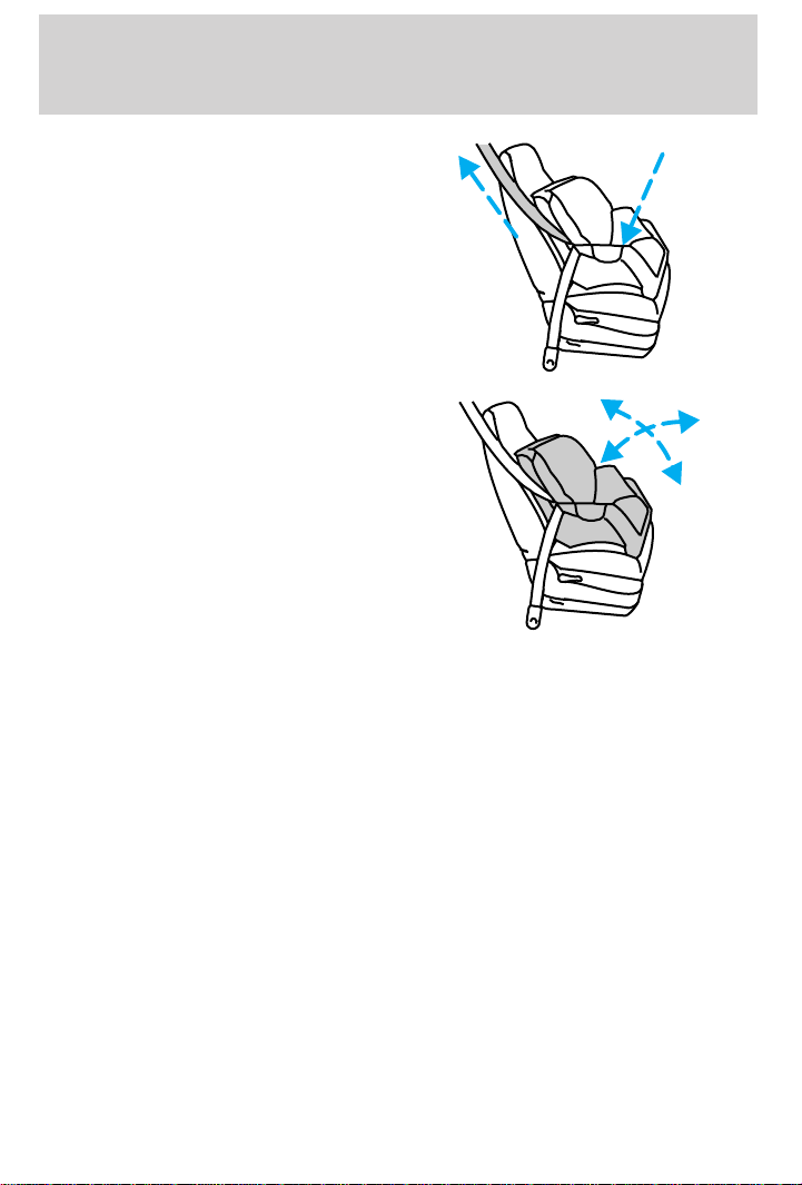
Seating and safety restraints
7. Pull the lap belt portion across
the child seat toward the buckle and
pull up on the shoulder belt while
pushing down with your knee on the
child seat.
8. Allow the safety belt to retract to
remove any slack in the belt.
9. Before placing the child in the
seat, forcibly tilt the seat forward
and back to make sure the seat is
securely held in place.
10. Try to pull the belt out of the retractor to make sure the retractor is
in the automatic locking mode (you should not be able to pull more belt
out). If the retractor is not locked, unbuckle the belt and repeat steps
two through nine.
Check to make sure the child seat is properly secured before each use.
Attaching safety seats with tether straps
Some manufacturers make safety seats that include a tether strap that
goes over the back of the vehicle seat and attaches to an anchoring
point. Other manufacturers offer the tether strap as an accessory.
Contact the manufacturer of your child safety seat for information about
ordering a tether strap.
Tether anchorage hardware (Coupe)
Attachment holes (at both rear seating positions) have been provided in
your vehicle to attach anchor hardware, if desired. Tether anchorage
hardware kits (part number 613D74) including instructions, may be
obtained at no charge from any Ford or Lincoln-Mercury dealer. All
vehicles built for sale in Canada include a tether anchor hardware kit.
80
Page 81
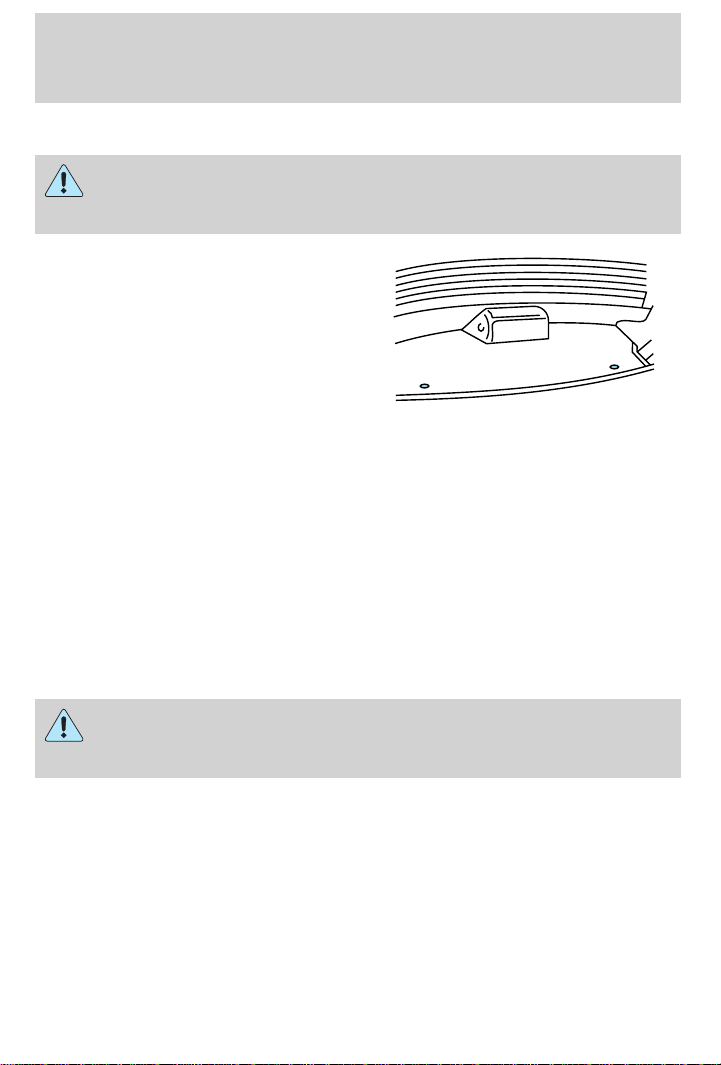
Seating and safety restraints
Be sure to follow the child safety seat manufacturer’s instructions.
Tighten the anchor according to specifications. Otherwise, the
safety seat may not be properly secured and the child may be
injured in a sudden stop or collision.
1. Install the child safety seat in the
rear right or rear left seat position.
For instructions on how to install
the seat, refer to Installing child
safety seats in combination lap
and shoulder belt seating
positions in this chapter.
2. Refer to the instructions provided in the tether anchor kit.
3. Refer to the instructions provided with your child safety seat to
securely attach the child safety seat by tether to the tether strap anchor
location.
Tether anchorage hardware (Sedan/Wagon)
Attachment holes (at each rear seating position) have been provided in
your vehicle to attach anchor hardware, if desired. Tether anchorage
hardware kits including instructions, may be obtained at no charge from
any Ford or Lincoln-Mercury dealer. All vehicles built for sale in Canada
include a tether anchor hardware kit.
Be sure to follow the child safety seat manufacturer’s instructions.
Tighten the anchor according to specifications. Otherwise, the
safety seat may not be properly secured and the child may be
injured in a sudden stop or collision.
1. Install the child safety seat in the rear right, rear left or rear center
seat position. For instructions on how to install the seat, refer to
Installing child safety seats in combination lap and shoulder belt
seating positions in this chapter.
2. Refer to the instructions provided in the tether anchor kit.
3. Refer to the instructions provided with your child safety seat to
securely attach the child safety seat by tether to the tether strap anchor
location.
81
Page 82
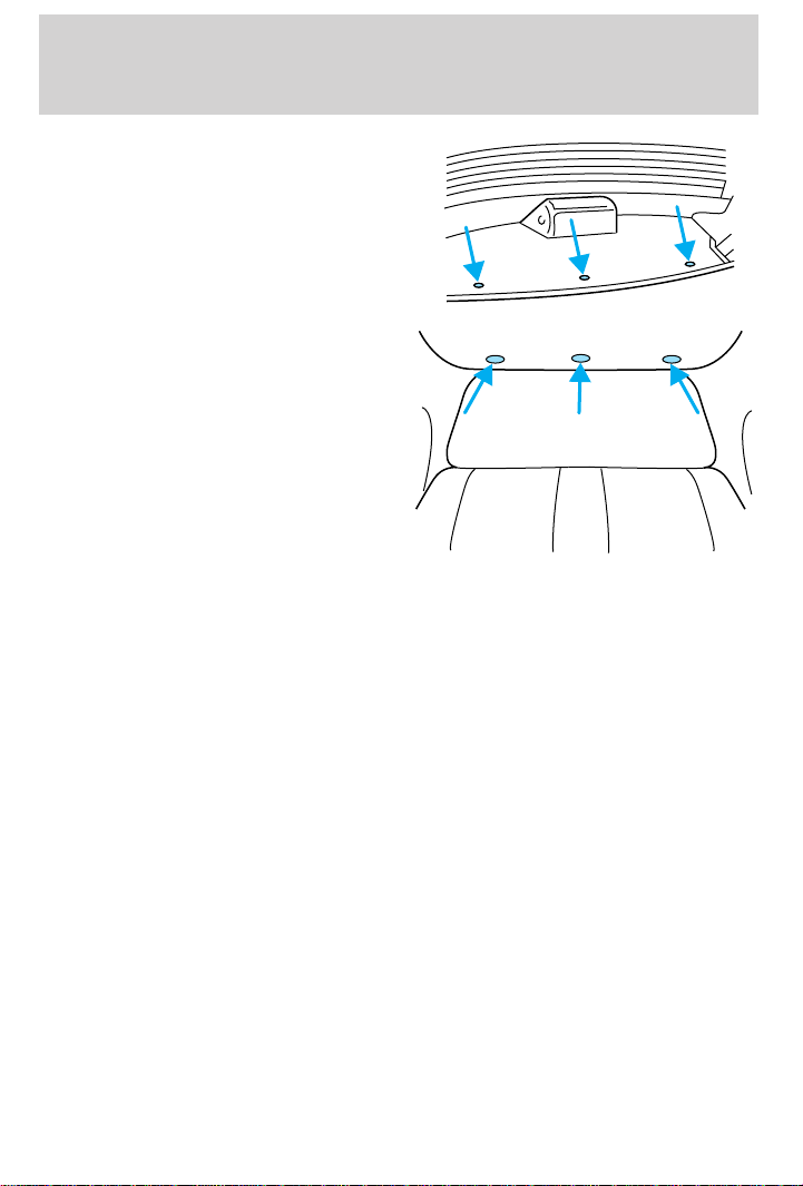
Seating and safety restraints
• Sedan
• Wagon
82
Page 83
Starting
PREPARING TO START YOUR VEHICLE
Engine starting is controlled by the ignition system. This system meets
all Canadian Interference-Causing Equipment standard requirements
regulating the impulse electrical field strength of radio noise.
When starting a fuel-injected engine, avoid pressing the accelerator
before or during starting. Only use the accelerator when you have
difficulty starting the engine. For more information on starting the
vehicle, refer to Starting the engine in this chapter.
Extended idling at high engine speeds can produce very high
temperatures in the engine and exhaust system, creating the risk
of fire or other damage.
Do not park, idle, or drive your vehicle in dry grass or other dry
ground cover. The emission system heats up the engine
compartment and exhaust system, which can start a fire.
Do not start your vehicle in a closed garage or in other enclosed
areas. Exhaust fumes can be toxic. Always open the garage door
before you start the engine. See Guarding against exhaust fumes in
this chapter for more instructions.
If you smell exhaust fumes inside your vehicle, have your dealer
inspect your vehicle immediately. Do not drive if you smell
exhaust fumes.
Important safety precautions
A computer system controls the engine’s idle revolutions per minute
(RPM). When the engine starts, the idle RPM runs faster to warm the
engine. If the engine idle speed does not slow down automatically, have
the vehicle checked. Do not allow the vehicle to idle for more than ten
minutes at the higher RPM.
Before starting the vehicle:
1. Make sure all vehicle occupants have buckled their safety belts. For
more information on safety belts and their proper usage, refer to the
Seating and safety restraints chapter.
83
Page 84
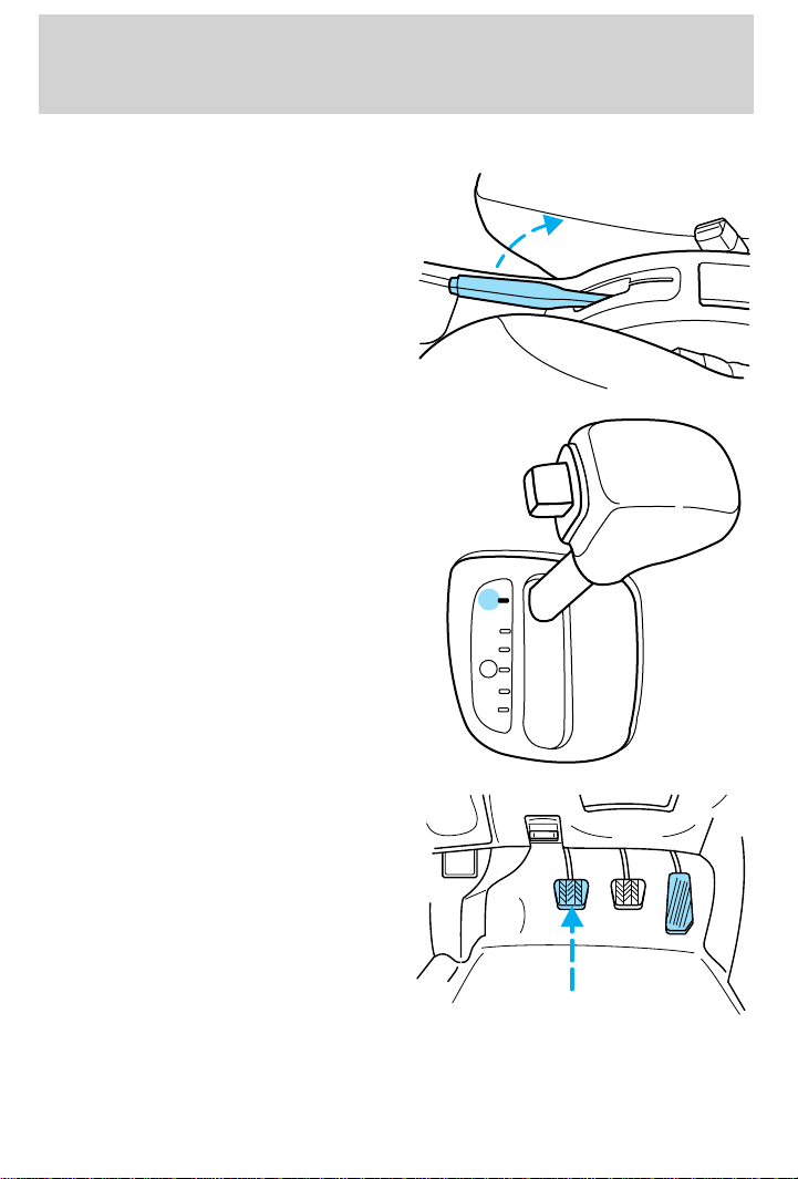
Starting
2. Make sure the headlamps and vehicle accessories are off.
3. Make sure the parking brake is
set.
If starting a vehicle with an
automatic transaxle:
• Make sure the gearshift is in P
(Park).
P
R
N
D
D
L
If starting a vehicle with a manual
transaxle:
• Push the clutch pedal to the
floor.
84
Page 85
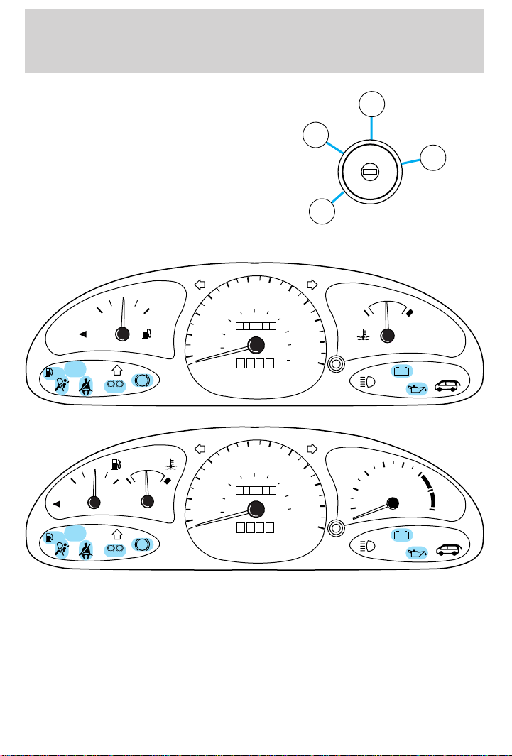
Starting
4. Turn the key to 3 (ON) without
turning the key to 4 (START).
50
10
10
20
20
30
30
40
40
40
20
km/h
40
20
km/h
60
MPH
50
60
MPH
LOW
FUEL
LOW
FUEL
SERVICE
ENGINE
SOON
FUEL FILL
SERVICE
ENGINE
SOON
1
/
EF
FUEL FILL
!
P
BRAKE
1
/
2
EF
!
P
BRAKE
2
ABS
CH
ABS
60
70
100
120
80
0000000
0 0 0
60
70
100
120
80
0000000
0 0 0
80
140
80
140
3
2
N
O
S
I
I
C
T
C
A
I
I
A
I
I
K
0
C
O
L
4
R
T
1
90
100
160
110
180
200
120
90
100
160
110
180
200
120
CH
THEFT
4
5
3
RPMx1000
2
1
THEFT
+–
6
7
8
+–
85
Page 86
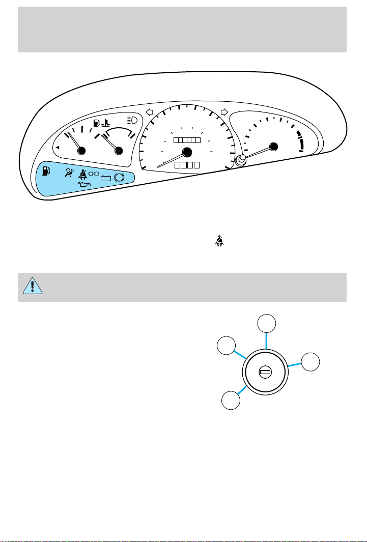
Starting
60 70
50
40
80
60
30
40
20
20
10
MPH
FUEL
FILL
LOW
FUEL
SERVICE
ENGINE
SOON
1
/
2
EF
!
P
BRAKE
CH
+–
ABS
Make sure the corresponding lights illuminate briefly. If a light fails to
illuminate, have the vehicle serviced.
• If the driver’s safety belt is fastened, the light may not illuminate.
STARTING THE ENGINE
Whenever you start your vehicle, release the key as soon as the
engine starts. Excessive cranking could damage the starter.
120
100
0000000
0 0 0
km/h
80
140
THEFT
4
90
160
100
180
110
120
5
6
3
RPMx1000
2
1
7
8
1. Turn the key to 4 (START)
without pressing the accelerator
pedal and release as soon as the
engine starts. The key will return to
3 (ON).
2
3
N
O
S
I
I
C
T
C
A
I
I
A
I
I
K
0
C
O
L
4
R
T
1
2. If the temperature is above –12° C (10° F) and the engine does not
start within five seconds on the first try, turn the key to OFF, wait ten
seconds and try again.
3. If the temperature is below -12° C (10° F) and the engine does not
start in fifteen seconds on the first try, turn the key OFF and wait ten
seconds and try again. If the engine does not start in two attempts,
86
Page 87

Starting
depress the accelerator and start the engine while holding the
accelerator down to the floor. Release the accelerator when the engine
starts.
4. After idling for a few seconds, apply the brake and release the parking
brake.
Using the engine block heater (if equipped)
An engine block heater warms the engine coolant, which improves
starting, warms up the engine faster and allows the heater-defroster
system to respond quickly. Use of an engine block heater is strongly
recommended if you live in a region where temperatures reach -23°C
(-10°F) or below.
For best results, plug the heater in at least three hours before starting
the vehicle. Using the heater for longer than three hours will not harm
the engine, so the heater can be plugged in the night before starting the
vehicle.
To prevent electrical shock, do not use your heater with
ungrounded electrical systems or two-pronged (cheater)
adapters.
Guarding against exhaust fumes
Although odorless and colorless, carbon monoxide is present in exhaust
fumes. Take precautions to avoid its dangerous effects.
If you ever smell exhaust fumes of any kind inside your vehicle,
have your dealer inspect and fix your vehicle immediately. Do
not drive if you smell exhaust fumes. These fumes are harmful and
could kill you.
Have the exhaust and body ventilation systems checked whenever:
• the vehicle is raised for service.
• the sound of the exhaust system changes.
• the vehicle has been damaged in a collision.
87
Page 88
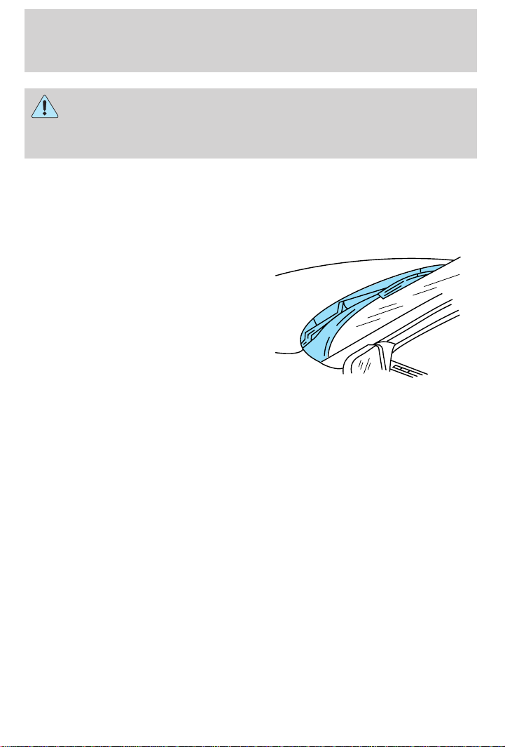
Starting
Engine exhaust, some of its constituents, and certain vehicle
components contain or emit chemicals known to the State of
California to cause cancer, and birth defects or other reproductive
harm.
Important ventilating information
If the engine is idling while the vehicle is stopped in an open area for
long periods of time, open the windows at least 2.5 cm (one inch).
Adjust the heating or air conditioning (if equipped) to bring in fresh air.
Improve vehicle ventilation by
keeping all air inlet vents clear of
snow, leaves and other debris.
88
Page 89

Driving
BRAKES
Your service brakes are self-adjusting. Refer to the scheduled
maintenance guide for scheduled maintenance.
Occasional brake noise is normal and often does not indicate a performance
concern with the vehicle’s brake system. In normal operation, automotive
brake systems may emit occasional or intermittent squeal or groan noises
when the brakes are applied. Such noises are usually heard during the first
few brake applications in the morning; however, they may be heard at any
time while braking and can be aggravated by environmental conditions such
as cold, heat, moisture, road dust, salt or mud. If a “metal-to-metal”,
“continuous grinding” or “continuous squeal” sound is present while braking,
the brake linings may be worn-out and should be inspected by a qualified
service technician.
Anti-lock brake system (ABS) (if equipped)
On vehicles equipped with an anti-lock braking system (ABS), a noise
from the hydraulic pump motor and pulsation in the pedal may be
observed during ABS braking events. Pedal pulsation coupled with noise
while braking under panic conditions or on loose gravel, bumps, wet or
snowy roads is normal and indicates proper functioning of the vehicle’s
anti-lock brake system. The ABS performs a self-check at 17 km/h (10
mph) after you start the engine and begin to drive away. A brief
mechanical noise may be heard during this test. This is normal. If a
malfunction is found, the ABS warning light will come on. If the vehicle
has continuous vibration or shudder in the steering wheel while braking,
the vehicle should be inspected by a qualified service technician.
The ABS operates by detecting the
onset of wheel lockup during brake
applications and compensating for this
tendency. The wheels are prevented
from locking even when the brakes
are firmly applied. The accompanying
illustration depicts the advantage of
an ABS equipped vehicle (on bottom)
to a non-ABS equipped vehicle (on
top) during hard braking with loss of front braking traction.
ABS warning lamp
ABS
The
warning lamp in the instrument cluster momentarily illuminates
when the ignition is turned on and the engine is off. If the light does not
89
Page 90
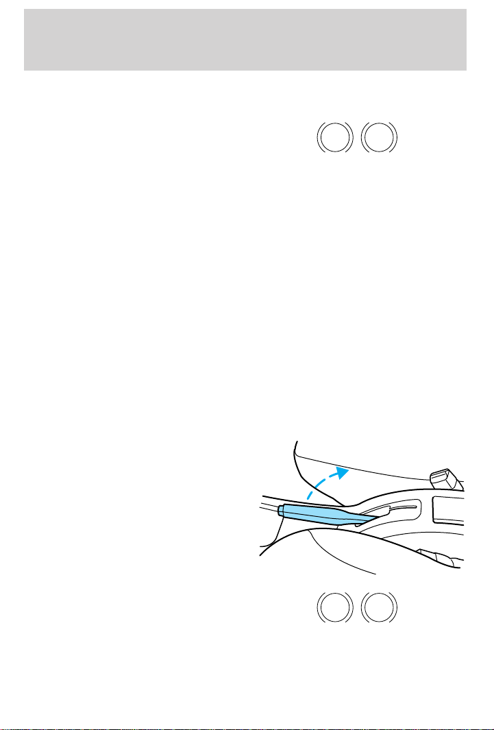
Driving
illuminate momentarily at start up, remains on or continues to flash, the
ABS needs to be serviced.
With the ABS light on, the anti-lock
brake system is disabled and normal
braking is still effective unless the
brake warning light also remains
illuminated with parking brake
released. (If your brake warning lamp illuminates, have your vehicle
serviced immediately).
Using ABS
• In an emergency or when maximum efficiency from the ABS is
required, apply continuous full force on the brake. The ABS will be
activated immediately, thus allowing you to retain full steering control
of your vehicle and, providing there is sufficient space, will enable you
to avoid obstacles and bring the vehicle to a controlled stop.
• The Anti-Lock system does not decrease the time necessary to apply
the brakes or always reduce stopping distance. Always leave enough
room between your vehicle and the vehicle in front of you to stop.
• We recommend that you familiarize yourself with this braking
technique. However, avoid taking any unnecessary risks.
Parking brake
Apply the parking brake whenever
the vehicle is parked. To set the
parking brake, pull the handle up as
far as possible.
P !
BRAKE
The BRAKE warning lamp in the
instrument cluster illuminates and
remains illuminated (when the
ignition is turned ON) until the
parking brake is released.
90
P !
BRAKE
Page 91
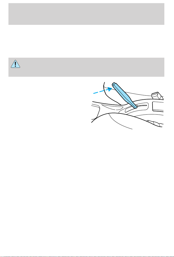
Driving
The parking brake is not recommended to stop a moving vehicle.
However, if the normal brakes fail, the parking brake can be used to stop
your vehicle in an emergency. Since the parking brake applies only the
rear brakes, the vehicle’s stopping distance will increase greatly and the
handling of your vehicle will be adversely affected.
Always set the parking brake fully and make sure that the
gearshift is securely latched in P (Park) (automatic transaxle) or
in 1 (First) (manual transaxle).
Push the button on the end of the
parking brake and push the handle
down as far as possible to release
the brake. Driving with the parking
brake on will cause the brakes to
wear out quickly and reduce fuel
economy.
STEERING
Your vehicle is equipped with power steering. Power steering uses energy
from the engine to help steer the vehicle.
To prevent damage to the power steering pump:
• Never hold the steering wheel to the extreme right or the extreme left
for more than a few seconds when the engine is running.
• Do not operate the vehicle with a low power steering pump fluid level.
If the power steering system breaks down (or if the engine is turned
off), you can steer the vehicle manually, but it takes more effort.
If the steering wanders or pulls, the condition could be caused by any of
the following:
• underinflated tire(s) on any wheel(s)
• high crown in center of road
• high crosswinds
• wheels out of alignment
• loose or worn components in steering linkage
91
Page 92
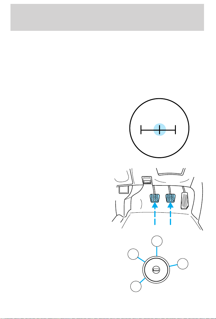
Driving
TRANSAXLE OPERATION
Manual transaxle (if equipped)
Using the clutch
Vehicles equipped with a manual transaxle have a starter interrupt
interlock that prevents cranking of the engine unless the clutch pedal is
depressed.
When starting a vehicle with a manual transaxle, you must:
1. Put the gearshift in the neutral
position.
2. Hold down the brake pedal.
3. Depress the clutch pedal.
4. Turn the ignition key to 4
(START), then let the engine idle
for a few seconds.
5. Release the brake pedal, then
slowly release the clutch pedal while
pressing down slowly on the
accelerator pedal.
Do not drive with your foot resting
on the clutch pedal and do not use
1
3
5
24R
3
2
1
N
O
S
I
I
C
T
C
A
I
I
A
I
R
I
T
K
0
C
O
L
4
92
Page 93
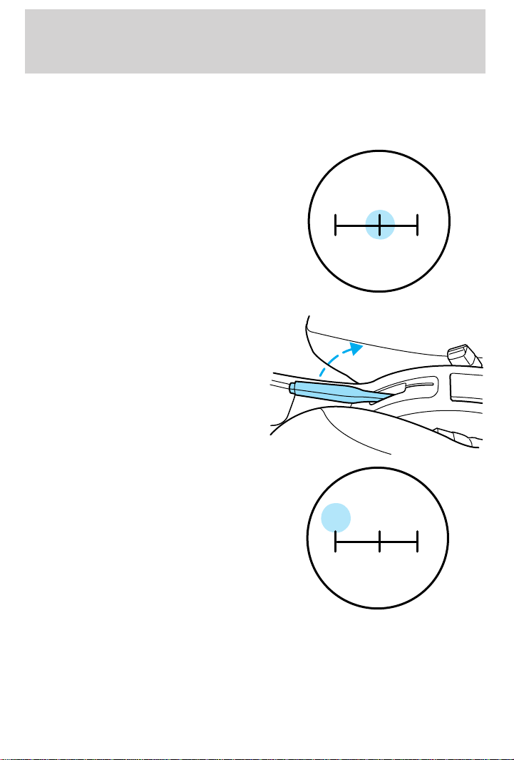
Driving
the clutch pedal to hold your vehicle at a standstill while waiting on a
hill. These actions will seriously reduce clutch life.
Parking your vehicle
1. Apply the brake and shift into the
neutral position.
2. Set the parking brake.
3. Shift into 1 (First).
1
3
5
24R
1
3
5
24R
93
Page 94
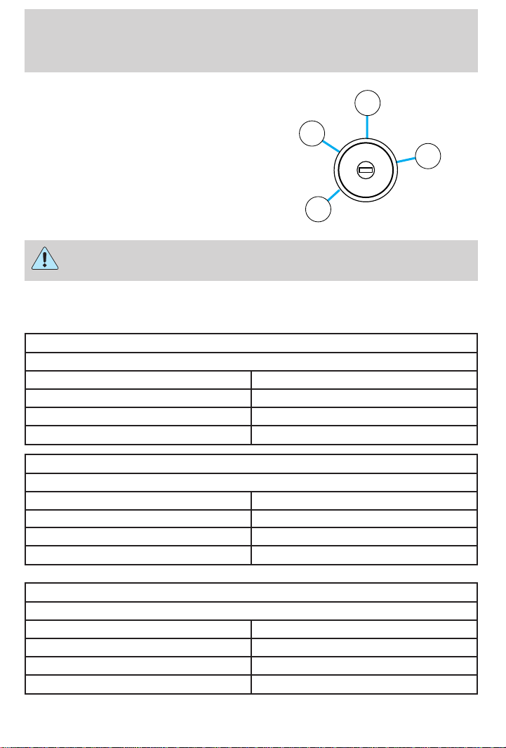
Driving
4. Turn engine off and remove the
key.
3
2
N
O
S
I
I
C
T
C
A
I
I
A
I
I
K
0
C
O
L
4
R
T
1
Do not park your vehicle in Neutral, it may move unexpectedly and
injure someone. Use 1 (First) gear and set the parking brake fully.
Recommended shift speeds
Upshift according to the following charts for best fuel economy:
Coupe
Upshifts when accelerating (recommended for best fuel economy)
1-2 21 km/h (13 mph)
2-3 40 km/h (25 mph)
3-4 53 km/h (33 mph)
4-5 70 km/h (44 mph)
Coupe
Upshifts when cruising (recommended for best fuel economy)
1-2 18 km/h (11 mph)
2-3 32 km/h (20 mph)
3-4 46 km/h (29 mph)
4-5 61 km/h (38 mph)
Sedan/Wagon
Upshifts when accelerating (recommended for best fuel economy)
1-2 22 km/h (14 mph)
2-3 40 km/h (25 mph)
3-4 55 km/h (34 mph)
4-5 70 km/h (44 mph)
94
Page 95
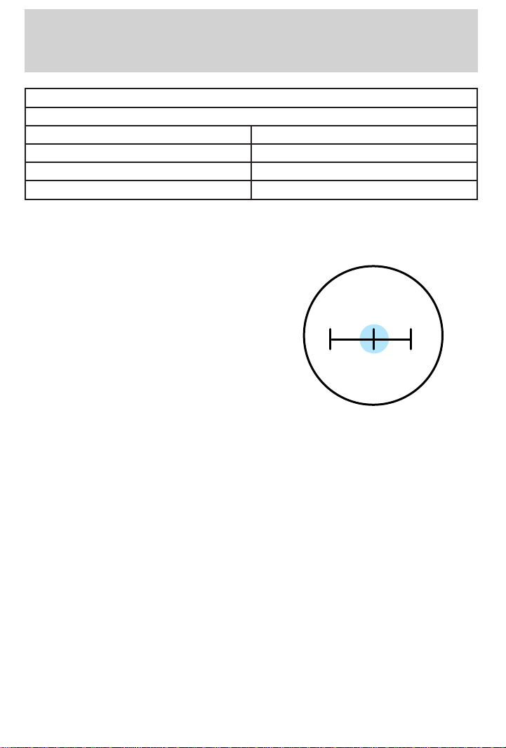
Driving
Sedan/Wagon
Upshifts when cruising (recommended for best fuel economy)
1-2 19 km/h (12 mph)
2-3 31 km/h (19 mph)
3-4 46 km/h (29 mph)
4-5 61 km/h (38 mph)
Reverse
Make sure that your vehicle is at a complete stop before you shift into R
(Reverse). Failure to do so may damage the transaxle.
Put the gearshift into the neutral
position and wait at least three
seconds before shifting into R
(Reverse).
1
3
5
24R
You can shift into R (Reverse) only by moving the gearshift from left of 3
(Third) and 4 (Fourth) gears before you shift into R (Reverse). This is a
special lockout feature which prevents you from shifting into R
(Reverse) when you downshift from 5 (Fifth).
Automatic transaxle (if equipped)
Brake-shift interlock
This vehicle is equipped with a brake-shift interlock feature that prevents
the gearshift from being moved from P (Park) unless the brake pedal is
depressed. If you cannot move the gearshift out of P (Park) with the
brake pedal depressed:
95
Page 96
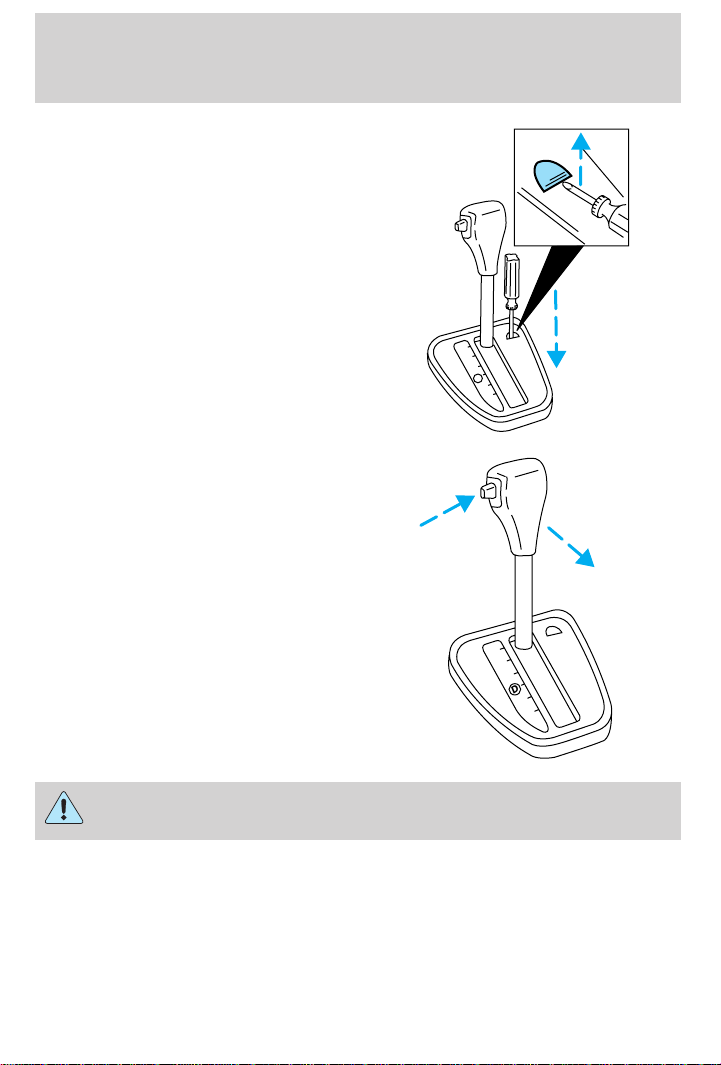
Driving
1. Continue depressing the brake
pedal, and remove the shift-lock
override cap with a 2.5 cm (1 inch)
or longer screwdriver.
2. Insert the screwdriver into the
shift-lock override opening and push
down.
3. Push and hold the thumb button.
4. Move the gearshift.
If it is necessary to use the above
procedure to move the gearshift, it
is possible that a fuse has blown and
the vehicle’s brakelamps may not be
operating properly. Refer to Fuses
and relays in the Roadside
emergencies chapter.
P
R
N
D
D
L
P
R
N
D
D
L
Do not drive your vehicle until you verify that the brakelamps
are working.
If your vehicle gets stuck in mud or snow it may be rocked out by
shifting from forward and reverse gears, stopping between shifts, in a
steady pattern. Press lightly on the accelerator in each gear.
Do not rock the vehicle for more than a few minutes. The
transaxle and tires may be damaged or the engine may overheat.
96
Page 97
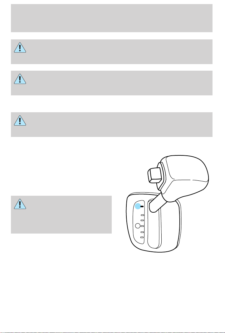
Driving
Always set the parking brake fully and make sure the gearshift is
latched in P (Park). Turn off the ignition whenever you leave
your vehicle.
If the parking brake is fully released, but the brake warning lamp
remains illuminated, the brakes may not be working properly.
See your dealer or a qualified service technician.
Understanding gearshift positions
Hold the brake pedal down while you move the gearshift lever
from P (Park) to another position. If you do not hold the brake
pedal down, your vehicle may move unexpectedly and injure someone.
P (Park)
Always come to a complete stop
before shifting into P (Park). Make
sure that the gearshift is securely
latched in P (Park). This locks the
transaxle and prevents the front
wheels from rotating.
Always set the parking
brake fully and make sure
the gearshift is latched in P
(Park). Turn off the ignition
whenever you leave your vehicle.
P
R
N
D
D
L
97
Page 98
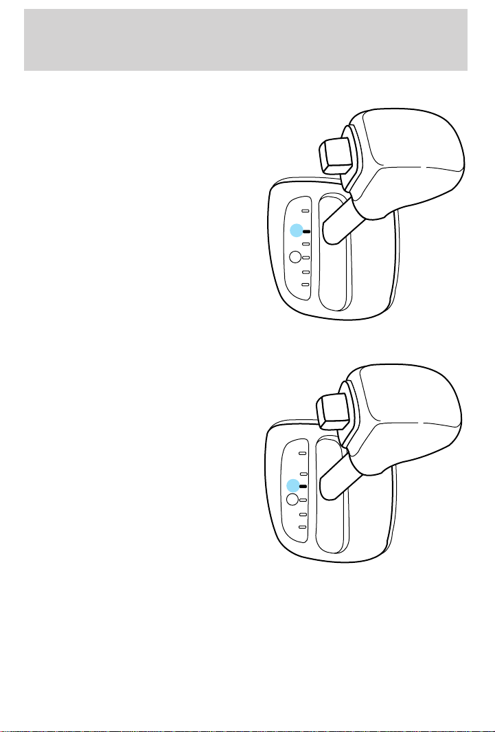
Driving
R (Reverse)
With the gearshift in R (Reverse),
the vehicle will move backward. You
should always come to a complete
stop before shifting in and out of R
(Reverse).
N (Neutral)
With the gearshift in the N
(Neutral) position, the vehicle can
be started and is free to roll. Hold
the brake pedal down while in this
position.
P
R
N
D
D
L
P
R
N
D
D
L
98
Page 99
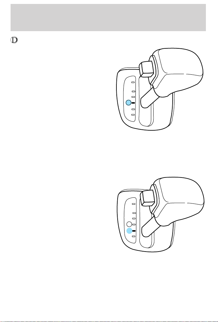
Driving
(Overdrive)
The overdrive position is the normal
driving position for an automatic
overdrive transaxle. It works the
same way as D (Drive) but shifts to
a fourth gear-an overdrive
gear-when your vehicle cruises at a
constant speed for any length of
time. This fourth gear will increase
your fuel economy when you travel
at cruising speeds.
Overdrive may not be appropriate for certain terrains. If the transaxle
shifts back and forth between third and fourth gears while you are
driving hilly roads or if your vehicle requires additional power for
climbing hills, shift into D (Drive).
D (Drive)
D (Drive) eliminates the needless
shifting between third and fourth
gears that your vehicle may do
when driving in hilly terrain. It also
gives more engine braking than
overdrive to slow your vehicle on
downgrades.
P
R
N
D
D
L
P
R
N
D
D
L
99
Page 100
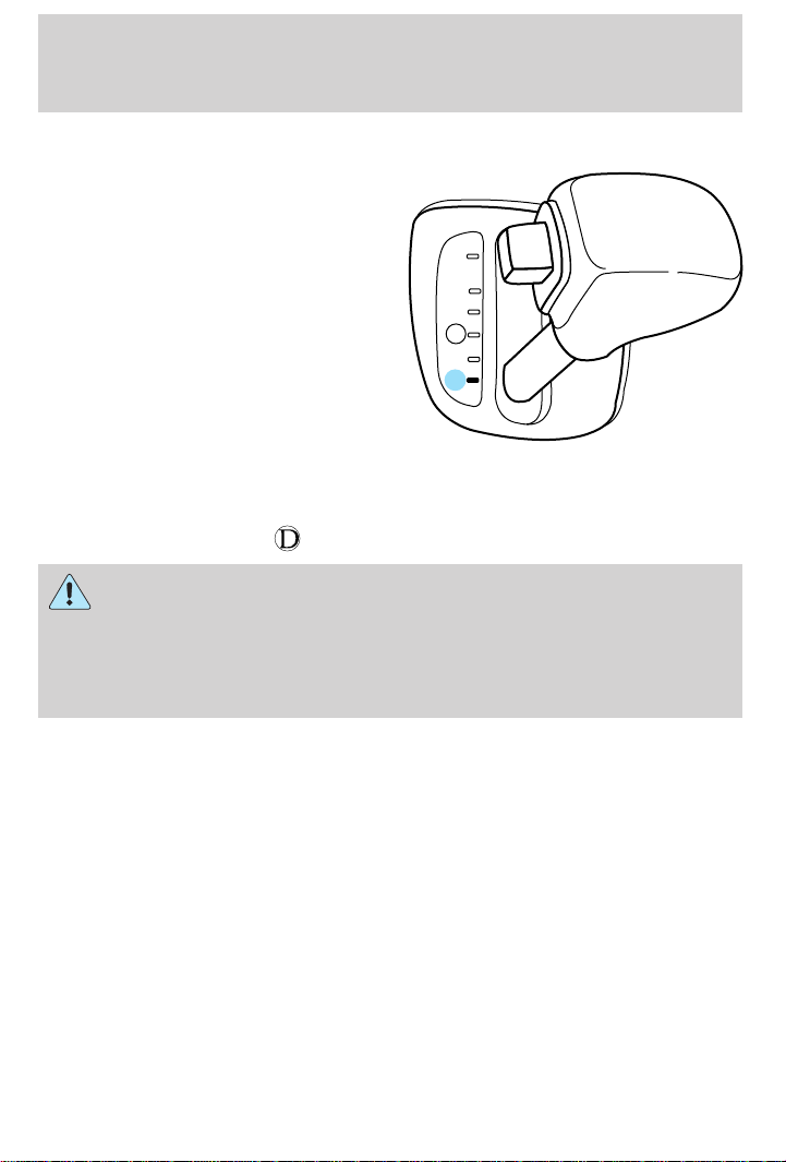
Driving
L (Low)
Use L (Low) when added engine
braking is desired or when
descending steep hills.
P
R
N
D
D
L
The automatic transaxle will shift into the proper gear to ascend any
grade without any need to shift to L (Low).
Do not go faster than 61 km/h (38 mph) when in this gear. You can
upshift from L (Low) to
When parking, do not use the gearshift in place of the parking
brake. Always set the parking brake fully and make sure that the
gearshift is securely latched in Park (P). Turn off the ignition
whenever you leave your vehicle. Never leave your vehicle unattended
while it is running. If you do not take these precautions, your vehicle
may move unexpectedly and injure someone.
(overdrive) at any time.
VEHICLE LOADING
Before loading a vehicle, familiarize yourself with the following terms:
• Base Curb Weight: Weight of the vehicle including any standard
equipment, fluids, lubricants, etc. It does not include passengers or
aftermarket equipment.
• Payload: Combined maximum allowable weight of cargo, passengers
and optional equipment. The payload equals the gross vehicle weight
rating minus base curb weight.
• GVW (Gross Vehicle Weight): Base curb weight plus payload
weight. The GVW is not a limit or a specification.
• GVWR (Gross Vehicle Weight Rating): Maximum total weight of
the base vehicle, passengers, optional equipment and cargo. The
GVWR is specific to each vehicle and is listed on the Safety
Compliance Label on the driver’s door pillar.
100
 Loading...